EP2150672B1 - Abschirmungsanordnung mit einem kopfteil in einer kompakten ausführung - Google Patents
Abschirmungsanordnung mit einem kopfteil in einer kompakten ausführung Download PDFInfo
- Publication number
- EP2150672B1 EP2150672B1 EP07722704.9A EP07722704A EP2150672B1 EP 2150672 B1 EP2150672 B1 EP 2150672B1 EP 07722704 A EP07722704 A EP 07722704A EP 2150672 B1 EP2150672 B1 EP 2150672B1
- Authority
- EP
- European Patent Office
- Prior art keywords
- screening
- bar
- screening arrangement
- roller
- top element
- Prior art date
- Legal status (The legal status is an assumption and is not a legal conclusion. Google has not performed a legal analysis and makes no representation as to the accuracy of the status listed.)
- Active
Links
Images


Classifications
-
- E—FIXED CONSTRUCTIONS
- E06—DOORS, WINDOWS, SHUTTERS, OR ROLLER BLINDS IN GENERAL; LADDERS
- E06B—FIXED OR MOVABLE CLOSURES FOR OPENINGS IN BUILDINGS, VEHICLES, FENCES OR LIKE ENCLOSURES IN GENERAL, e.g. DOORS, WINDOWS, BLINDS, GATES
- E06B9/00—Screening or protective devices for wall or similar openings, with or without operating or securing mechanisms; Closures of similar construction
- E06B9/24—Screens or other constructions affording protection against light, especially against sunshine; Similar screens for privacy or appearance; Slat blinds
- E06B9/40—Roller blinds
Definitions
- the present invention relates to a screening arrangement for screening an aperture of a frame, comprising a top element having a front side, a bottom element having a top edge and a bottom edge, a finger grip being defined on the bottom element, and a screening body, said screening body including a first end edge and a second end edge, said first end edge being accommodated in the top element and the second end edge fastened to the top edge of the bottom element, said bottom element being movable manually by operation of said finger grip between a non-screening position close to the top element and a screening position at a distance from the top element, said screening body defining a screening plane, said top element accommodating a roller bar and a guide bar.
- a screening arrangement is known from US 6 873 461 B1 .
- such screening arrangements contain a number of parts that should be concealed from the surroundings. This is primarily due to the fact that impurities in the surrounding air, such as dust and pollution, and daylight, should be prevented from reaching these parts, as they are normally sensitive to such external influences. As a second consideration, these parts may be of a less aesthetically pleasing design due to their technical character. Consequently, many attempts are made at concealing these parts in the top element of the screening arrangement. However, as the top element and some other parts, such as side rails, are exposed to the surroundings at all times, i.e. both in the screening position and in the non-screening position, it is a fundamental requirement to make the top element as functional and inconspicuous as possible.
- the screening arrangement In practically all fields of application of the screening arrangement, there is focus on reducing in particular the height dimension of the top element as much as possible. This requirement is mostly relevant in cases, in which the screening arrangement is mounted in the frame aperture itself, and in which the top element actually covers a part of the aperture to be screened. However, also in screening arrangements arranged outside the aperture to be screened, i.e. in most cases above the aperture, it is an aim to affect the building façade as little as possible. Evidently, the height of the top element is even more crucial in case the screening arrangement comprises a guide bar in addition to the roller bar, thus requiring extra space.
- screening arrangements which may furthermore involve different installation situations
- complete enclosure of the screening arrangement may be advantageous. This is for instance the case in screening arrangements positioned on the outside of a building.
- screening arrangements are intended for automatic operation by means of e.g. an electrical motor, operating means in the form of cords being fastened to the bottom element.
- said top element is provided with a top rail forming the front side of the top element and being connected to a cover of the top element, said cover including a top cover portion and a back cover portion, the roller bar being positioned closer to the back cover portion and farther from the top cover portion than the guide bar.
- the bottom element is positioned at substantially the same level of height as the roller bar in the non-screening position, the bottom edge of the bottom element being positioned at the same level as or slightly above the lowermost portion of the screening body stored on the roller bar. Consequently, the roller bar including the stored screening body is hidden behind the bottom element.
- this configuration provides for the possibility of hiding the roller bar including the stored screening body in the following installation situation: when the screening arrangement according to the invention is utilized to screen a window built-into an inclined roof surface, and the top of the window is positioned at a height corresponding to the line of sight of a person standing in the room, the line of sight extends at an angle other than perpendicular to the screening plane.
- the bottom element is positioned below the guide bar in the non-screening position.
- the bottom element has a general U-shape between the top and bottom edges comprising an integrally formed bar projecting in the direction facing the back cover portion, the finger grip being provided by said U-shape.
- the side of the U-shape facing inwards provides a grip that is easily manageable.
- the U-shape has the further advantage that it blocks the view into the guide bar from below the screening arrangement.
- the top portion of said bar in the non-screening position is situated immediately below the guide bar and the back portion of the bar is situated immediately in front of the front portion of the screening body stored on the roller bar.
- the degree of overlap lies in the interval 1-10 mm, preferably 2-8 mm, most preferably 4-6 mm.
- the roller bar and the guide bar have substantially the same length, diameter and material thickness.
- this embodiment is particularly advantageous as the dimensions of the roller bar and guide bar makes it possible to optimize the utilization of the space available in the top element.
- the screening arrangement further comprises a guide bar, and the screening body is wound in mutually opposite directions on the roller bar and the guide bar, and that the front side of the screening body faces inwards on the roller bar in the non-screening position.
- the top element includes two end pieces, wherein the roller bar is spring-biased and mounted on a roller shaft, and wherein said roller shaft and one of the end pieces constitute an integral unit provided as a one-piece moulded unit.
- the need for complicated connections at this point is rendered superfluous.
- the reduction of the number of parts entails that the simplified assembly aimed at is obtained and, simultaneously, a very strong transition between the roller shaft and the end piece is provided.
- the integral transition makes it possible to make the roller shaft slimmer. Consequently, the roller bar may be made with a smaller diameter, and hence the entire top element may be formed with smaller overall dimensions.
- the spatial requirements at the ends of the top element at the end piece/roller shaft transition are reduced. The additional space thus obtained may for instance be utilized to make the screening body wider. This is an advantage from an aesthetical point of view in any screening arrangement.
- the top rail extends in said first longitudinal direction between a first mitred end and a second mitred end
- the screening arrangement further comprises two side rails, each of said side rails having a first end and second mitred end, the second mitred end of each side rail being adapted to be joined to the first and second mitred end, respectively, of said top rail
- the screening arrangement furthermore includes a set of angular brackets, each angular bracket being adapted to cooperate with reception means in the back side of the top rail and in the back side of the respective side rail.
- the top rail has a predetermined height and each side rail has a predetermined width, and wherein said predetermined height is substantially the same as said predetermined width, the mitre joint thus being a 45° mitre joint.
- the top rail may be formed with a small predetermined height due to the compact design and optimum utilization of the space available in the top element, the three elements visible from inside the room render the screening arrangement slender, elegant and inconspicuous.
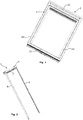
- Figs 1 and 2 show an embodiment of a screening arrangement generally designated 1.
- the screening arrangement is adapted to be mounted on a frame constituted by a sash 2 representing a window.
- the sash 2 is adapted to be connected with a stationary frame (not shown), which in a mounted position of the window lines an opening in a building.
- frame is to be understood as incorporating any substantially rectangular structure positioned in any opening in a building, whether in a wall or the roof, and surrounding an aperture to be screened.
- a screening arrangement according to the invention may just as well be mounted on the stationary frame instead of the sash and may also be utilized in connection with e.g. windows having a frame only, or in doors.
- the sash 2 has a top piece 21, a bottom piece 22 and two side pieces 23 and 24 surrounding an aperture, which is covered by a suitable panel element such as a glazing in the form of an insulating pane (not shown).
- the screening arrangement 1 comprises a top element 4 positioned at the sash top piece 21, a screening body 6 (not shown in Figs 1 or 2 , cf. however Fig. 13 ) and a bottom element 7. At its upper end edge, the screening body 6 is accommodated in the top element 4 and its opposed, lower end edge is fastened to the bottom element 7.
- the bottom element 7 is adapted to act as a handle during operation of the screening arrangement 1, i.e.
- the screening arrangement may be operated by other means, e.g. by electrical operating means.
- the screening arrangement 1 comprises two side rails 8 and 9 adapted to be connected to a respective side piece 23 and 24 and to the top element 4, in a manner to be described in further detail below.
- the screening arrangement comprises a roller blind having as its screening body 6 a cloth or fabric, and of which the top element 4 includes a spring-biased roller bar.
- the top element 4 includes a spring-biased roller bar.
- other screening arrangements having other kinds of screening bodies and other configurations of the top element are conceivable as well.
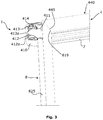
- Figs 3 and 4 depicting the top element 4 in one embodiment of the screening arrangement it may be seen that the top element 4 has a left-hand end piece 410 and a right-hand end piece 420 (not shown in these Figures, cf., however, Fig. 6 ).
- the terms “left-hand” and “right-hand” refer to the orientation shown in for instance Figs 1 to 3 and are utilized for reasons of convenience only.
- the terms “front” and “black” are utilized to denote the sides of the screening arrangement, "front” being the side intended to face inwards into the room of the building, and “black” the outwards facing side.
- the top element 4 comprises a cover 430 extending almost throughout the entire length of the top element 4 from the left-hand end piece 410 to the right-hand end piece 420, the end pieces thus constituting the end faces of the top element 4.
- the cover 430 is connected to a top rail 440.
- the connection between the top rail 440 and the remaining portion of the top element, i.e. the cover 430 is made integral, e.g. by extruding the top element as a profile including the cover 430 as well as the top rail 440.
- the end piece 410 is adapted to be fastened to the cover 430 by means of e.g. a screw inserted in screw hole 416 (cf. Fig. 6 ) to be received in threaded track 449 in the cover 430.
- the top rail 440 has a slightly longer extension in the longitudinal direction than the cover portion 430.
- top rail 440 In the mounted position of the screening arrangement the top rail 440 is joined to side rails 8, 9 in mitre joints by means of angular brackets 85. To that end the top rail 440 has two mitred ends, of which one mitred end 445 is shown in Figs 3 and 4 to be joined to a respective mitred end of the side rails. In Fig. 5 , the left-hand side rail 8 is shown with its mitred end 819. The side rail 8 furthermore has a flange 823 ending at a distance from the mitred end 819. This difference, in combination with the difference in length between the top rail 440 and the cover portion 430, leaves room for the end piece 410.
- each side rail 8, 9 has a predetermined width, and in the embodiment shown the predetermined height is substantially the same as said predetermined width, the mitre joint thus being a 45° mitre joint.
- the mitre joint thus being a 45° mitre joint.
- Other angles are conceivable, however, this entails that a similar configuration of the front sides of the three elements, i.e. top rail and two side rails, is not achievable.
- the side edges of the screening body 6 are guided in the side rails 8, 9 in a manner known per se, for instance by means of a number of guide beads mounted at a distance from each other along each side edge.
- the side rails 8, 9 serve the purpose of improving the light-proofing properties of the screening arrangement, as they overlap the side edges of the screening body in the mounted position of the screening arrangement.
- the side rails may contribute to holding the screening body in position.
- the bottom edge of the screening body 6 is connected with the bottom element 7 in any suitable manner, and the ends of the bottom element 7 are advantageously guided in the side rails as well.
- the bottom element 7 may be provided with a sealing profile 76 (cf. Fig. 13 ) to abut against the bottom side piece of the frame.
- the screening arrangement comprises a parallel guidance cord system comprising two cords (not shown), one cord being adapted to extend from the left-hand lower corner of the sash, up through or along the bottom element 7 and further up to the top element 4.
- the other cord is routed in a mirror-inverted manner.
- each cord is connected with a respective pre-tensioning device adapted to be connected with the top element 4 in a track and/or to press against the top cover portion 431 of the cover 430.
- the pre-tensioning devices entail that the cords are held at a suitable tension all of the time, thereby ensuring that the bottom element 7 is at all times kept substantially in parallel with the top and bottom pieces 21, 22 of the sash 2 during operation of the screening arrangement. In the mounted position, the cords are hidden behind the side rails.
- the top element 4 accommodates a guide bar 470 and a roller bar 460.
- the screening body 6 is fastened to the roller bar 460 along its upper end edge in any suitable manner known per se.
- the guide bar 470 guides the screening body 6 onto the roller bar 460, which serves to collect and store the screening body 6 in the non-screening and partially screened positions of the screening arrangement, or even in the fully screened position, in case the screening body contains surplus material.
- the screening body is wound in mutually opposite directions on the roller bar and the guide bar.
- roller bar 460 is spring-biased and, hence, provides the preload toward the non-screening position required to roll up the screening body 6.
- the screening body 6 extends almost up to the inner side of the end pieces 410, 420, thus providing for an optimum usage of the space available also in the longitudinal direction of the top element 4.
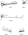
- the preload acting on the roller bar 460 is provided by a spring device that will be described in further detail below during the description of Figs 8 to 12 .
- the roller bar 460 and the guide bar 470 are formed as hollow cylindrical bodies.
- the roller bar 460 and the guide bar 470 may be more or less identical, both as regards length, diameter and material thickness.
- the diameter of the roller bar 460, and of the guide bar 470 may be approximately 12-20 mm, e.g. 16 mm.
- different configurations between the two bars are conceivable.
- the guide bar 470 serves three primary purposes: Firstly, it ensures that the screening body 6 is guided in substantially the same screening plane along the height of the sash aperture. On the roller bar 460, the total external diameter of the roller bar 460 and the stored portion of the screening body 6 varies with the length of screening body unrolled. In screening arrangements not provided with a guide bar or other guide means, this entails that the screening body unrolled from the roller bar in a fully or almost fully screened position is positioned close to the roller bar and hence a distance from the side rails. The provision of the guide bar 470 eliminates the effects of this diameter variation.
- the guide bar 470 makes it possible to obtain a suitable tension of the screening body 6 to avoid wrinkles of the screening body and prevents that the screening body is rolled up askew. This effect is even more pronounced in one embodiment, in which the guide bar 470 has a configuration tapering towards each end. The tapering might for instance lie in the interval 2-5 mm per m length of the guide bar 470.
- the side of the screening body 6 facing inwards in the screening positions i.e. the front side facing towards the room in the position of use of the screening arrangement, faces inwards when stored on the roller bar 460 and, consequently, the back side faces outwards on the roller bar. In this manner, the front side of the screening body is protected from light when rolled up on the roller bar.
- the roller bar 460 is positioned closer to the back cover portion 432 than the guide bar 470, whereas the guide bar 470 is positioned closer to the top cover portion 431 than the roller bar 460.
- the top element 4 is of a compact design. This will be described in further detail following the below description of the remaining parts of the screening arrangement.
- a roller shaft 461 is integral with the left-hand end piece 410.
- the roller shaft 461 could be formed as an integral unit with the other, right-hand end piece 420.
- the integral connection is obtained by moulding the end piece 410 and the roller shaft 461 in one piece, i.e. without subsequent joining of any parts, to form the one piece unit comprising the end piece and the roller shaft.
- the moulding is carried out by any appropriate method on the basis of a suitable plastic material, such as polyamide, for instance PA6, or polyethylene, which has a good durability against wear and tear, and sufficient resistance towards torsion and bending.
- the roller shaft 461 extends between a left hand end 462 joined to the end piece 410 by stub portion 463, and a right hand end 465.
- the roller shaft 461 is formed as a solid body part.
- a plurality of further functions is integrated into the end pieces.
- the end piece 410 has a stub 471 acting as means for receiving bearings for one end (the left-hand end) of the guide bar 470, said bearings being constituted by end plug 472 having a bearing ring 473.
- the right-hand end piece 420 is provided with a stub (not shown) similar to stub 471 for receiving the bearings for the right-hand end of the guide bar 470 in the form of end plug 474 and a bearing ring corresponding to bearing ring 473.
- the right-hand end piece 420 is provided with a second stub (not shown) intended for receiving end plug 464 for supporting the right-hand end of roller bar 460.
- the left-hand end of roller bar 460 is supported on stub portion 463 by an end plug 482 of the spring device.
- the connection with the roller bar 460 may be carried out in any suitable manner, e.g. by means of a stepped portion of the end plug 482.
- the roller shaft 461 is, as mentioned in the above, preferably formed as a solid body part, stub 471 of left-hand end piece 410 and the not-shown stubs on right-hand end piece 420 may be hollow.
- roller bar and the guide bar on the respective end plugs may be carried out by friction alone, or by means of mechanical fastening means such as protruding portions of the end plugs interacting with apertures in the roller and guide bars, or vice versa.
- the roller shaft, stubs, bearings and spring device form part of the suspension arrangement of the roller bar and guide bar of the screening arrangement.
- the diameter of the roller shaft 461 may for instance lie in the interval 4-8 mm, e.g. 6 mm.
- the spring device generally designated 480 comprises a torsion spring extending between a left-hand end 481 securely fastened to end plug 482 and a right-hand end 483.
- torsion spring end 483 is secured in a slit 466 in the right-hand end 465 of roller shaft 461.
- the slit 466 opens towards the top of the roller shaft 461 and extends towards the bottom thereof, ending at a certain distance from the bottom such that a bridge of material is still present at the bottom.
- the slit 466 could open in any direction and have other extensions in the radial direction, e.g. extend to the centre of the roller shaft 461.
- the retention of the torsion spring in the slit 466 is carried out by a bent portion (not shown) of the torsion spring end 483. Furthermore, retention is secured by means of support element 490, which has the additional function of preventing the roller shaft 461 from splitting open.
- the support element 490 is, in turn, retained on the roller shaft 461 by means of a groove 467 at the end 465 of roller shaft 461.
- the support means 490 has a maximum external diameter adapted to fit into the roller bar 460 in order to support the roller bar 460. It is to be understood that other kinds of spring devices may be utilized as well, e.g. spring devices making use of springs of other kinds than the shown torsion spring.
- the end piece 410 comprises portions constituting coupling means for cooperation with bracket members positioned on the side piece 23 of the window sash 2.
- the opposite, right-hand end piece has an outer side configured in a substantially mirror-inverted manner.
- the bracket members may, in principle, have any suitable form as long as they permit swift and secure connection with the screening arrangement.
- One example of such bracket members is shown in Applicant's published international applications Nos WO 2005/008013 and WO 2006/048014 .
- Such a coupling member is traditionally formed as a separate part connected with the remaining parts of the screening arrangement, one example being described in detail in Applicant's published international application No. WO 00/47858 .
- the portions serving the function of coupling means corresponding to the coupling members of the prior art are made integral with the respective end pieces.
- These coupling portions are substantially identical, however mirror-inverted, on the left-hand end piece 410 and the right-hand end piece 420, and only the coupling portions of the left hand piece 410 will be described.
- the outer side of end piece 410 comprises an upper guide surface 411 and a lower guide surface 412 formed on a respective upstanding rib on the end piece 410 itself.
- the rib acts as reinforcement of the end piece 410.
- the screening arrangement 1 has a general direction of mounting, as described in further detail in the above-mentioned Nos WO 2005/008013 and WO 2006/048014 .
- the guide surfaces 411, 412 extend in parallel with that general direction of mounting.
- the lower guide surface 412 is formed with an inclined portion forming a ramp 412a.
- the ramp 412a is formed at the end intended to be positioned at the back when mounted, and is thus the end which is first brought into contact with the bracket member.
- the ramp 412a thus serves to facilitate correct positioning of the top element 4 of the screening arrangement.
- resilient engagement means are provided at the upper guide surface 412. These means comprise a tongue 413 extending from a point at the back of end piece 410 in the direction towards the front such that one portion, back portion 413a, of the tongue has a direction substantially parallel with that of the ramp 412a on the lower guide surface and one portion is substantially parallel with the guide surfaces 411 and 412.
- the resilient tongue 413 has the effect of allowing temporary positioning of the top element 4 on the bracket member.
- the tongue 413 furthermore includes snap engagement means in the form of upstanding retaining pawl 414 to allow for a more permanent retention of the top element in the frame.
- the top element 4 is easily connected with the bracket members: Initially, the top element is moved generally in the mounting direction from inside the room towards the outside, i.e. towards the pane of the frame, however slightly from below. Each end piece is guided onto the bracket member via the ramp 412a and the back portion 413a of tongue 413 during increased impression of the tongue 413.
- the tongue 413 thus exerts a corresponding resilient pressure on the bracket member resulting in a slightly clamping action on the top element.
- the top element is moved further on in the mounting direction with the guide surfaces 411, 412 in sliding engagement with the corresponding sides of the bracket member.
- the retaining pawl 414 snaps out into engagement with an edge of the bracket member.
- the thickness of the end piece 410 itself i.e. of the plane portion from which the roller shaft and the guide surfaces etc. mentioned in the above emanate, is relatively small, for instance 1-2 mm, e.g. 1.5 mm.
- end piece 410 has spring means 415 (cf. Fig. 6 ) for cooperation with a cord system of a further screening arrangement (not shown).
- the top element 4 has a front side, a top side and a back side.
- the front side is constituted by top rail 440, and the top and back sides by cover 430, i.e. by the top cover portion 431 and the back cover portion 432, respectively.
- cover 430 i.e. by the top cover portion 431 and the back cover portion 432, respectively.
- the top element 4 is designed with such a height measured from the bottom of the back cover portion 432 to the top cover portion side 431 that it encloses a major part of the roller bar 460 including the screening body 6 stored on the roller bar 460 in the non-screening position.
- the top element 4 is designed with such a depth measured from the top rail 440 to the back cover portion 431 that the bottom element 7 may be positioned at the same level of height as the roller bar 460 in the non-screening position.
- the bottom element 7 has a general U-shape, the legs of the U extending integrally into the top and bottom edges 71 and 72, respectively. As shown in Fig. 13 , the top edge 71 of the bottom element 7 is positioned above bottom edge 444 of the top rail 440 of the top element 4 in the non-screening position.
- the bottom edge 72 is positioned at the same level as or slightly above the lowermost portion of the screening body 6 stored on the roller bar 460.
- the screening arrangement according to the invention is utilized to screen a window built-into an inclined roof surface, and the top of the window is positioned at a height corresponding to the line of sight S of a person standing in the room, the line of sight S extends at an angle other than perpendicular to the screening plane. Consequently, the roller bar 460 including the stored screening body 6 is hidden behind the bottom element 7.
- the bottom element 7 has a general U-shape between the top and bottom edges 71, 72 comprising an integrally formed bar 74, 75 projecting in the direction facing the back cover portion 432, the finger grip 73 being provided by said U-shape.
- the top portion 74 of said bar is situated immediately below the guide bar 470 and the back portion 75 of the bar is situated immediately in front of the front portion of the screening body 6 stored on the roller bar 460.
- the slight overlap should not exceed the distance between the top edge 71 and the lower end of the U-shape and may for instance lie in the interval 1-10 mm, preferably 2-8 mm, most preferably 4-6 mm.
- the height and depth dimensions and the particular positioning of the roller bar 460 and the guide bar 470 provide for an extremely compact design of the top element 4.
- each end piece may be formed as an integral unit with a roller shaft.
- the configuration of the two sides is mirror-inverted and the screening arrangement may e.g. comprise two torsion springs wound in opposite directions, or comprise springs of two different kinds.
Landscapes
- Engineering & Computer Science (AREA)
- Structural Engineering (AREA)
- Architecture (AREA)
- Civil Engineering (AREA)
- Operating, Guiding And Securing Of Roll- Type Closing Members (AREA)
Claims (11)
- Abschirmungsanordnung (1) zur Abschirmung einer Öffnung eines Rahmens, mit:einem oberen Bauteil (4) mit einer Vorderseite (440),einem unteren Bauteil (7) mit einer oberen Kante (71) und einer unteren Kante (72), einem Fingergriff auf dem unteren Bauteil, undeinem Abschirmkörper (6) mit einer ersten Endkante und einer zweiten Endkante, wobei die erste Endkante in dem oberen Bauteil (4) aufgenommen ist und die zweite Endkante an der oberen Kante des unteren Bauteils (7) befestigt ist, wobei das untere Bauteil durch Bedienung des Fingergriffs zwischen einer nicht-abschirmenden Position nahe des oberen Bauteils und einer abschirmenden Position, beabstandet von dem oberen Bauteil, manuell bewegbar ist,wobei das obere Bauteil (4) eine Rollstange (460) und eine Führungsstange (470) aufnimmt,dadurch gekennzeichnet, dassdas obere Bauteil (4) eine obere Schiene (440) aufweist, die die Vorderseite des oberen Bauteils bildet und mit einer Abdeckung (430) des oberen Bauteils (4) verbunden ist, wobei die Abdeckung (430) einen oberen Abdeckungsabschnitt (431) und einen rückwärtigen Abdeckungsabschnitt (432) aufweist, wobei die Rollstange (460) näher an dem rückwärtigen Abdeckungsabschnitt (432) und weiter entfernt von dem oberen Abdeckungsabschnitt (431) positioniert ist als die Führungsstange (470), dassdas obere Bauteil (4) derartige Abmessungen aufweist, dass die obere Kante (71) des unteren Bauteils (7) dazu eingerichtet ist, in der nicht-abschirmenden Position die untere Kante (444) der oberen Schiene (440) des oberen Bauteils (4) leicht zu überdecken, wobei die leichte Überdeckung in dem Intervall 1-10 mm, vorzugsweise 2-8 mm, besonders bevorzugt 4-6 mm, liegt, dassdas untere Bauteil (7) in der nicht-abschirmenden Position unter der Führungsstange (470) positioniert ist, und dassdas untere Bauteil (7) eine allgemeine U-Form zwischen den oberen und den unteren Kanten (71, 72) aufweist, mit einer integral ausgebildete Stange (74, 75), die sich in der Richtung erstreckt, die dem rückwärtigen Abdeckungsabschnitt (432) zugewandt ist, wobei der Fingergriff (73) durch die U-Form bereitgestellt wird.
- Abschirmungsanordnung nach Anspruch 1, wobei das untere Bauteil (7) im Wesentlichen auf der gleichen Höhe wie die Rollstange (460) in der nicht-abschirmenden Position positioniert ist, wobei die untere Kante (72) des unteren Bauteils (7) auf der gleichen Höhe oder leicht über dem untersten Abschnitt des auf der Rollstange (460) gelagerten Abschirmkörpers (6) positioniert ist.
- Abschirmungsanordnung nach Anspruch 1, wobei der obere Abschnitt (74) der Stange in der nicht-abschirmenden Position unmittelbar unter der Führungsstange (470) liegt und der rückwärtige Abschnitt (75) der Stange unmittelbar vor dem vorderen Abschnitt des auf der Rollstange (460) gelagerten Abschirmkörpers (6) liegt.
- Abschirmungsanordnung nach einem der vorhergehenden Ansprüche, wobei die Rollstange (460) und die Führungsstange (470) im Wesentlichen die gleiche Länge, den gleichen Durchmesser und die gleiche Materialdicke aufweisen.
- Abschirmungsanordnung nach einem der vorhergehenden Ansprüche, wobei das obere Bauteil (4) zwei Endstücke (410, 420) aufweist, wobei die Rollstange (460) federvorgespannt (480) und auf einer Rollenwelle (461) montiert ist, und wobei die Rollenwelle (461) und eines der Endstücke (410) eine integrale Einheit (410, 461) bilden, die als einstückig geformte Einheit vorgesehen ist,
wobei die integrale Einheit (410, 461) und das andere Endstück (420) vorzugsweise jeweils Kopplungsmittel (411-414) aufweisen, die dazu ausgebildet sind, mit einem Klammerelement in der Rahmenöffnung verbunden zu werden,
wobei die Kopplungselemente vorzugsweise elastische Eingriffsmittel (413) und Schnappeingriffsmittel (414) aufweisen. - Abschirmungsanordnung nach Anspruch 5, wobei die integrale Einheit (410, 461) und das andere Endstück (420) jeweils Mittel (471) zum Aufnehmen der Lager für die Führungsrolle (470) aufweisen.
- Abschirmungsanordnung nach einem der vorhergehenden Ansprüche, wobei eine die Feder-Vorspannkraft bereitstellende Federvorrichtung (480) eine Torsionsfeder beinhaltet, die an einem Ende (482) fest mit einem Endstopfen verbunden ist, der einen auf der Rollenwelle frei rotierbaren Lagerring aufweist, und die an dem anderen Ende (483) in einem Schlitz (466) in der Rollenwelle gesichert ist,
wobei die Torsionsfeder vorzugsweise durch ein Trägerelement (490) in dem Schlitz gesichert ist. - Abschirmungsanordnung nach einem der Ansprüche 5 bis 7, wobei die integrale Einheit (410, 461) aus einem Kunststoffmaterial wie Polyamid oder Polyethylen geformt ist.
- Abschirmungsanordnung nach einem der Ansprüche 5 bis 8, wobei das andere Endstück (420) als ein geformtes Stück, vorzugsweise aus einem Kunststoffmaterial, wie Polyamid oder Polyethylen, vorgesehen ist.
- Abschirmungsanordnung nach einem der vorhergehenden Ansprüche, wobei die Abschirmungsanordnung weiter eine Führungsstange (470) aufweist, und wobei der Abschirmkörper (6) in zueinander entgegengesetzten Richtungen auf die Rollenstange (460) und die Führungsstange (470) gewickelt ist, und wobei die Vorderseite des Abschirmkörpers (6) auf der Rollenstange (470) in der nichtabschirmenden Position nach innen gerichtet ist.
- Abschirmungsanordnung nach einem der Ansprüche 1 bis 10, wobei die obere Schiene (440) sich in der ersten Längsrichtung zwischen einem ersten Gehrungsende und einem zweiten Gehrungsende erstreckt, und wobei die Abschirmungsanordnung weiter zwei Seitenschienen (8, 9) aufweist, wobei jede der Seitenschienen (8, 9) ein erstes Ende und zweites Gehrungsende aufweist, wobei das zweite Gehrungsende jeder der Schienen (8, 9) dazu angepasst ist, mit dem ersten bzw. mit dem zweiten Gehrungsende der oberen Schiene (440) verbunden zu werden, und wobei die Abschirmungsanordnung weiterhin einen Satz von Winkelklammern (85) aufweist, wobei jede Winkelklammer dazu angepasst ist, mit Aufnahmemitteln in der rückwärtigen Seite der oberen Schiene (440) und in der rückwärtigen Seite der jeweiligen Seitenschiene (8, 9) zusammenzuwirken,
wobei die obere Schiene (440) vorzugsweise eine vorbestimmte Höhe und jede der Seitenschienen (8, 9) eine vorbestimmte Breite aufweist, und wobei die vorbestimmte Höhe im Wesentlichen mit der vorbestimmten Breite übereinstimmt, so dass die Gehrungsverbindung eine 45°-Gehrungsverbindung ist.
Applications Claiming Priority (1)
| Application Number | Priority Date | Filing Date | Title |
|---|---|---|---|
| PCT/DK2007/050049 WO2008131761A1 (en) | 2007-04-26 | 2007-04-26 | A screening arrangement including a top element having a compact configuration |
Publications (2)
| Publication Number | Publication Date |
|---|---|
| EP2150672A1 EP2150672A1 (de) | 2010-02-10 |
| EP2150672B1 true EP2150672B1 (de) | 2017-04-05 |
Family
ID=38621972
Family Applications (1)
| Application Number | Title | Priority Date | Filing Date |
|---|---|---|---|
| EP07722704.9A Active EP2150672B1 (de) | 2007-04-26 | 2007-04-26 | Abschirmungsanordnung mit einem kopfteil in einer kompakten ausführung |
Country Status (5)
| Country | Link |
|---|---|
| EP (1) | EP2150672B1 (de) |
| CN (2) | CN101652528A (de) |
| DE (1) | DE202008005957U1 (de) |
| PL (1) | PL2150672T3 (de) |
| WO (1) | WO2008131761A1 (de) |
Families Citing this family (7)
| Publication number | Priority date | Publication date | Assignee | Title |
|---|---|---|---|---|
| WO2010089118A1 (en) | 2009-02-09 | 2010-08-12 | Hunter Douglas Industries B.V. | Spring system for roller blinds |
| DE102009048305A1 (de) | 2009-10-05 | 2011-04-07 | Warema Renkhoff Se | Verschattungsanlage mit Behangumlenkung |
| NL1039407C2 (en) | 2012-02-27 | 2013-08-28 | Hunter Douglas Ind Bv | Architectural covering having a drive mechanism for extending and retracting a covering member between opposite first and second end positions. |
| DE202013102604U1 (de) * | 2013-06-18 | 2013-07-24 | Hans Iversen | Befestigungsvorrichtung für Sonnen- und Blickschutzanordnungen, insbesondere an Dachfenstern |
| PL4177437T3 (pl) | 2021-11-03 | 2026-01-05 | Vkr Holding A/S | Układ zasłaniający zawierający element chroniący przed światłem |
| DK4400689T3 (da) | 2023-01-13 | 2025-12-01 | Vkr Holding As | Afskærmningsanordning med en transportanordning og fremgangsmåde til montering af en afskærmningsanordning |
| US20240426107A1 (en) | 2023-06-20 | 2024-12-26 | Vkr Holding A/S | Screening arrangement with a top casing and a bottom element comprising a screening body receiving space |
Family Cites Families (9)
| Publication number | Priority date | Publication date | Assignee | Title |
|---|---|---|---|---|
| GB1440915A (en) * | 1972-08-04 | 1976-06-30 | Beauty Blinds Ltd | Roller screen assembly for an aperture sliding gate valve assemblies |
| US4126174A (en) * | 1977-07-20 | 1978-11-21 | Moriarty James P | Flexible sheet rollup window structure |
| NL8200931A (nl) * | 1982-03-05 | 1983-10-03 | Roelof Pieter Snier | Huis voor een rolgordijn. |
| DE19646910A1 (de) * | 1996-11-13 | 1998-05-14 | Warema Renkhoff Gmbh & Co Kg | Rolladen-Vorbauelement |
| AU745402C (en) | 1999-02-12 | 2003-01-09 | Vkr Holding A/S | Supporting means for a screening device |
| DE20210855U1 (de) * | 2002-07-18 | 2003-05-28 | Tussinger, Philipp, 76275 Ettlingen | Rollovorrichtung |
| US6873461B1 (en) * | 2003-02-25 | 2005-03-29 | Draper, Inc. | Case for roller-operated screen system |
| EP1500775A1 (de) | 2003-07-21 | 2005-01-26 | VKR Holding A/S | Halterung und Abschirmvorrichtung zum Gebrauch mit einer solchen Halterung |
| WO2006048014A1 (en) | 2004-11-01 | 2006-05-11 | Vkr Holding A/S | Supporting means facilitating the installation of a screening device, and a window for cooperation with the supporting means |
-
2007
- 2007-04-26 PL PL07722704T patent/PL2150672T3/pl unknown
- 2007-04-26 CN CN200780052740A patent/CN101652528A/zh active Pending
- 2007-04-26 WO PCT/DK2007/050049 patent/WO2008131761A1/en not_active Ceased
- 2007-04-26 EP EP07722704.9A patent/EP2150672B1/de active Active
-
2008
- 2008-04-25 DE DE202008005957U patent/DE202008005957U1/de not_active Expired - Lifetime
- 2008-04-28 CN CNU2008201051462U patent/CN201214969Y/zh not_active Expired - Lifetime
Non-Patent Citations (1)
| Title |
|---|
| None * |
Also Published As
| Publication number | Publication date |
|---|---|
| CN101652528A (zh) | 2010-02-17 |
| PL2150672T3 (pl) | 2017-09-29 |
| EP2150672A1 (de) | 2010-02-10 |
| CN201214969Y (zh) | 2009-04-01 |
| DE202008005957U1 (de) | 2008-11-20 |
| WO2008131761A1 (en) | 2008-11-06 |
Similar Documents
| Publication | Publication Date | Title |
|---|---|---|
| EP2153007B1 (de) | Abschirmanordnung mit einem endstück mit einer integrierten wickelwelle | |
| WO2008131761A1 (en) | A screening arrangement including a top element having a compact configuration | |
| CA2987228C (en) | Upper guide track and assembly for a retractable screen | |
| US20090056885A1 (en) | Head rail assembly | |
| US9217280B2 (en) | Screening arrangement comprising means for mounting side rails and method of mounting such a screening arrangement | |
| EP2150670B1 (de) | Eine führungsstange enthaltende abschirmungsanordnung | |
| EP2333194B1 (de) | Überdachung | |
| JP2017155564A (ja) | 上吊引戸 | |
| EP2171170B1 (de) | System zum anbringen von fensterrollläden an einem wintergartendach | |
| EP4177437B1 (de) | Abschirmanordnung mit einem lichtschutzelement | |
| JP2020204252A (ja) | 防火用開閉装置 | |
| JPH11166379A (ja) | 日除け機構およびこれを備えた窓用シャッター | |
| WO2008043358A1 (en) | A method for securing a screening device to a window, a set of parts and use of a glazing bead of a window | |
| JP6474254B2 (ja) | 浸水防止構造 | |
| KR200440937Y1 (ko) | 롤블라인드용 블라인드지의 설치구조 | |
| KR20090069396A (ko) | 문틈모서리커버 | |
| JP4033261B2 (ja) | シャッタカーテンのレール構造 | |
| KR200373398Y1 (ko) | 블라인드용 브래킷의 설치구조 | |
| ES2348880B1 (es) | "dispositivo de persiana enrollable, y pieza retenedora para dicho dispositivo". | |
| KR20140144889A (ko) | 접이식 창틀 | |
| JP7246241B2 (ja) | 建築用シャッター装置におけるガイドレールの取付け構造および取付け方法 | |
| KR20100002632U (ko) | 차양 장치의 커버 | |
| EP2690246B1 (de) | Abschirmungsanordnung mit Mitteln zur Montage von Seitenschienen und Verfahren zur Montage solch einer Abschirmungsanordnung | |
| EP2920395B1 (de) | Fenster mit einer abschirmanordnung und verbesserter lichtdichtheit | |
| IT202400001371A1 (it) | Elemento terminale applicato al bordo inferiore del telo flessibile di una tenda avvolgibile e tenda avvolgibile che impiega detto elemento terminale |
Legal Events
| Date | Code | Title | Description |
|---|---|---|---|
| PUAI | Public reference made under article 153(3) epc to a published international application that has entered the european phase |
Free format text: ORIGINAL CODE: 0009012 |
|
| 17P | Request for examination filed |
Effective date: 20091126 |
|
| AK | Designated contracting states |
Kind code of ref document: A1 Designated state(s): AT BE BG CH CY CZ DE DK EE ES FI FR GB GR HU IE IS IT LI LT LU LV MC MT NL PL PT RO SE SI SK TR |
|
| AX | Request for extension of the european patent |
Extension state: AL BA HR MK RS |
|
| RIN1 | Information on inventor provided before grant (corrected) |
Inventor name: EKFELDT, BENT Inventor name: THOMSEN, PEDER SOLSO |
|
| DAX | Request for extension of the european patent (deleted) | ||
| 17Q | First examination report despatched |
Effective date: 20150817 |
|
| GRAP | Despatch of communication of intention to grant a patent |
Free format text: ORIGINAL CODE: EPIDOSNIGR1 |
|
| INTG | Intention to grant announced |
Effective date: 20161104 |
|
| GRAS | Grant fee paid |
Free format text: ORIGINAL CODE: EPIDOSNIGR3 |
|
| GRAA | (expected) grant |
Free format text: ORIGINAL CODE: 0009210 |
|
| AK | Designated contracting states |
Kind code of ref document: B1 Designated state(s): AT BE BG CH CY CZ DE DK EE ES FI FR GB GR HU IE IS IT LI LT LU LV MC MT NL PL PT RO SE SI SK TR |
|
| REG | Reference to a national code |
Ref country code: GB Ref legal event code: FG4D |
|
| REG | Reference to a national code |
Ref country code: CH Ref legal event code: EP |
|
| REG | Reference to a national code |
Ref country code: AT Ref legal event code: REF Ref document number: 882014 Country of ref document: AT Kind code of ref document: T Effective date: 20170415 |
|
| REG | Reference to a national code |
Ref country code: FR Ref legal event code: PLFP Year of fee payment: 11 |
|
| REG | Reference to a national code |
Ref country code: IE Ref legal event code: FG4D |
|
| REG | Reference to a national code |
Ref country code: DE Ref legal event code: R096 Ref document number: 602007050471 Country of ref document: DE |
|
| REG | Reference to a national code |
Ref country code: NL Ref legal event code: FP |
|
| REG | Reference to a national code |
Ref country code: LT Ref legal event code: MG4D |
|
| REG | Reference to a national code |
Ref country code: AT Ref legal event code: MK05 Ref document number: 882014 Country of ref document: AT Kind code of ref document: T Effective date: 20170405 |
|
| PG25 | Lapsed in a contracting state [announced via postgrant information from national office to epo] |
Ref country code: ES Free format text: LAPSE BECAUSE OF FAILURE TO SUBMIT A TRANSLATION OF THE DESCRIPTION OR TO PAY THE FEE WITHIN THE PRESCRIBED TIME-LIMIT Effective date: 20170405 Ref country code: AT Free format text: LAPSE BECAUSE OF FAILURE TO SUBMIT A TRANSLATION OF THE DESCRIPTION OR TO PAY THE FEE WITHIN THE PRESCRIBED TIME-LIMIT Effective date: 20170405 Ref country code: GR Free format text: LAPSE BECAUSE OF FAILURE TO SUBMIT A TRANSLATION OF THE DESCRIPTION OR TO PAY THE FEE WITHIN THE PRESCRIBED TIME-LIMIT Effective date: 20170706 Ref country code: FI Free format text: LAPSE BECAUSE OF FAILURE TO SUBMIT A TRANSLATION OF THE DESCRIPTION OR TO PAY THE FEE WITHIN THE PRESCRIBED TIME-LIMIT Effective date: 20170405 Ref country code: LT Free format text: LAPSE BECAUSE OF FAILURE TO SUBMIT A TRANSLATION OF THE DESCRIPTION OR TO PAY THE FEE WITHIN THE PRESCRIBED TIME-LIMIT Effective date: 20170405 |
|
| PG25 | Lapsed in a contracting state [announced via postgrant information from national office to epo] |
Ref country code: SE Free format text: LAPSE BECAUSE OF FAILURE TO SUBMIT A TRANSLATION OF THE DESCRIPTION OR TO PAY THE FEE WITHIN THE PRESCRIBED TIME-LIMIT Effective date: 20170405 Ref country code: IS Free format text: LAPSE BECAUSE OF FAILURE TO SUBMIT A TRANSLATION OF THE DESCRIPTION OR TO PAY THE FEE WITHIN THE PRESCRIBED TIME-LIMIT Effective date: 20170805 Ref country code: BG Free format text: LAPSE BECAUSE OF FAILURE TO SUBMIT A TRANSLATION OF THE DESCRIPTION OR TO PAY THE FEE WITHIN THE PRESCRIBED TIME-LIMIT Effective date: 20170705 Ref country code: LV Free format text: LAPSE BECAUSE OF FAILURE TO SUBMIT A TRANSLATION OF THE DESCRIPTION OR TO PAY THE FEE WITHIN THE PRESCRIBED TIME-LIMIT Effective date: 20170405 |
|
| REG | Reference to a national code |
Ref country code: CH Ref legal event code: PL |
|
| REG | Reference to a national code |
Ref country code: DE Ref legal event code: R097 Ref document number: 602007050471 Country of ref document: DE |
|
| REG | Reference to a national code |
Ref country code: IE Ref legal event code: MM4A |
|
| PG25 | Lapsed in a contracting state [announced via postgrant information from national office to epo] |
Ref country code: SK Free format text: LAPSE BECAUSE OF FAILURE TO SUBMIT A TRANSLATION OF THE DESCRIPTION OR TO PAY THE FEE WITHIN THE PRESCRIBED TIME-LIMIT Effective date: 20170405 Ref country code: MC Free format text: LAPSE BECAUSE OF FAILURE TO SUBMIT A TRANSLATION OF THE DESCRIPTION OR TO PAY THE FEE WITHIN THE PRESCRIBED TIME-LIMIT Effective date: 20170405 Ref country code: DK Free format text: LAPSE BECAUSE OF FAILURE TO SUBMIT A TRANSLATION OF THE DESCRIPTION OR TO PAY THE FEE WITHIN THE PRESCRIBED TIME-LIMIT Effective date: 20170405 Ref country code: EE Free format text: LAPSE BECAUSE OF FAILURE TO SUBMIT A TRANSLATION OF THE DESCRIPTION OR TO PAY THE FEE WITHIN THE PRESCRIBED TIME-LIMIT Effective date: 20170405 Ref country code: RO Free format text: LAPSE BECAUSE OF FAILURE TO SUBMIT A TRANSLATION OF THE DESCRIPTION OR TO PAY THE FEE WITHIN THE PRESCRIBED TIME-LIMIT Effective date: 20170405 |
|
| PLBE | No opposition filed within time limit |
Free format text: ORIGINAL CODE: 0009261 |
|
| STAA | Information on the status of an ep patent application or granted ep patent |
Free format text: STATUS: NO OPPOSITION FILED WITHIN TIME LIMIT |
|
| PG25 | Lapsed in a contracting state [announced via postgrant information from national office to epo] |
Ref country code: LU Free format text: LAPSE BECAUSE OF NON-PAYMENT OF DUE FEES Effective date: 20170426 Ref country code: CH Free format text: LAPSE BECAUSE OF NON-PAYMENT OF DUE FEES Effective date: 20170430 Ref country code: LI Free format text: LAPSE BECAUSE OF NON-PAYMENT OF DUE FEES Effective date: 20170430 Ref country code: IT Free format text: LAPSE BECAUSE OF FAILURE TO SUBMIT A TRANSLATION OF THE DESCRIPTION OR TO PAY THE FEE WITHIN THE PRESCRIBED TIME-LIMIT Effective date: 20170405 |
|
| 26N | No opposition filed |
Effective date: 20180108 |
|
| REG | Reference to a national code |
Ref country code: BE Ref legal event code: MM Effective date: 20170430 |
|
| REG | Reference to a national code |
Ref country code: FR Ref legal event code: PLFP Year of fee payment: 12 |
|
| PG25 | Lapsed in a contracting state [announced via postgrant information from national office to epo] |
Ref country code: IE Free format text: LAPSE BECAUSE OF NON-PAYMENT OF DUE FEES Effective date: 20170426 |
|
| PG25 | Lapsed in a contracting state [announced via postgrant information from national office to epo] |
Ref country code: SI Free format text: LAPSE BECAUSE OF FAILURE TO SUBMIT A TRANSLATION OF THE DESCRIPTION OR TO PAY THE FEE WITHIN THE PRESCRIBED TIME-LIMIT Effective date: 20170405 Ref country code: BE Free format text: LAPSE BECAUSE OF NON-PAYMENT OF DUE FEES Effective date: 20170430 |
|
| PG25 | Lapsed in a contracting state [announced via postgrant information from national office to epo] |
Ref country code: MT Free format text: LAPSE BECAUSE OF NON-PAYMENT OF DUE FEES Effective date: 20170426 |
|
| PG25 | Lapsed in a contracting state [announced via postgrant information from national office to epo] |
Ref country code: HU Free format text: LAPSE BECAUSE OF FAILURE TO SUBMIT A TRANSLATION OF THE DESCRIPTION OR TO PAY THE FEE WITHIN THE PRESCRIBED TIME-LIMIT; INVALID AB INITIO Effective date: 20070426 |
|
| PG25 | Lapsed in a contracting state [announced via postgrant information from national office to epo] |
Ref country code: CY Free format text: LAPSE BECAUSE OF NON-PAYMENT OF DUE FEES Effective date: 20170405 |
|
| PG25 | Lapsed in a contracting state [announced via postgrant information from national office to epo] |
Ref country code: TR Free format text: LAPSE BECAUSE OF FAILURE TO SUBMIT A TRANSLATION OF THE DESCRIPTION OR TO PAY THE FEE WITHIN THE PRESCRIBED TIME-LIMIT Effective date: 20170405 |
|
| PG25 | Lapsed in a contracting state [announced via postgrant information from national office to epo] |
Ref country code: PT Free format text: LAPSE BECAUSE OF FAILURE TO SUBMIT A TRANSLATION OF THE DESCRIPTION OR TO PAY THE FEE WITHIN THE PRESCRIBED TIME-LIMIT Effective date: 20170405 |
|
| PGFP | Annual fee paid to national office [announced via postgrant information from national office to epo] |
Ref country code: CZ Payment date: 20230328 Year of fee payment: 17 |
|
| PGFP | Annual fee paid to national office [announced via postgrant information from national office to epo] |
Ref country code: NL Payment date: 20240315 Year of fee payment: 18 |
|
| PGFP | Annual fee paid to national office [announced via postgrant information from national office to epo] |
Ref country code: PL Payment date: 20240315 Year of fee payment: 18 |
|
| PG25 | Lapsed in a contracting state [announced via postgrant information from national office to epo] |
Ref country code: CZ Free format text: LAPSE BECAUSE OF NON-PAYMENT OF DUE FEES Effective date: 20240426 |
|
| PG25 | Lapsed in a contracting state [announced via postgrant information from national office to epo] |
Ref country code: CZ Free format text: LAPSE BECAUSE OF NON-PAYMENT OF DUE FEES Effective date: 20240426 |
|
| PGFP | Annual fee paid to national office [announced via postgrant information from national office to epo] |
Ref country code: FR Payment date: 20250321 Year of fee payment: 19 |
|
| PGFP | Annual fee paid to national office [announced via postgrant information from national office to epo] |
Ref country code: GB Payment date: 20250306 Year of fee payment: 19 |
|
| PGFP | Annual fee paid to national office [announced via postgrant information from national office to epo] |
Ref country code: DE Payment date: 20250305 Year of fee payment: 19 |
|
| REG | Reference to a national code |
Ref country code: NL Ref legal event code: MM Effective date: 20250501 |
|
| PG25 | Lapsed in a contracting state [announced via postgrant information from national office to epo] |
Ref country code: NL Free format text: LAPSE BECAUSE OF NON-PAYMENT OF DUE FEES Effective date: 20250501 |
|
| PG25 | Lapsed in a contracting state [announced via postgrant information from national office to epo] |
Ref country code: PL Free format text: LAPSE BECAUSE OF NON-PAYMENT OF DUE FEES Effective date: 20250426 |