EP2150743B1 - Element raccord de serrage pour un tuyau - Google Patents
Element raccord de serrage pour un tuyau Download PDFInfo
- Publication number
- EP2150743B1 EP2150743B1 EP08760345A EP08760345A EP2150743B1 EP 2150743 B1 EP2150743 B1 EP 2150743B1 EP 08760345 A EP08760345 A EP 08760345A EP 08760345 A EP08760345 A EP 08760345A EP 2150743 B1 EP2150743 B1 EP 2150743B1
- Authority
- EP
- European Patent Office
- Prior art keywords
- clamping sleeve
- sleeve
- spacer
- tube
- slit
- Prior art date
- Legal status (The legal status is an assumption and is not a legal conclusion. Google has not performed a legal analysis and makes no representation as to the accuracy of the status listed.)
- Active
Links
Images

Classifications
-
- F—MECHANICAL ENGINEERING; LIGHTING; HEATING; WEAPONS; BLASTING
- F16—ENGINEERING ELEMENTS AND UNITS; GENERAL MEASURES FOR PRODUCING AND MAINTAINING EFFECTIVE FUNCTIONING OF MACHINES OR INSTALLATIONS; THERMAL INSULATION IN GENERAL
- F16L—PIPES; JOINTS OR FITTINGS FOR PIPES; SUPPORTS FOR PIPES, CABLES OR PROTECTIVE TUBING; MEANS FOR THERMAL INSULATION IN GENERAL
- F16L33/00—Arrangements for connecting hoses to rigid members; Rigid hose-connectors, i.e. single members engaging both hoses
- F16L33/02—Hose-clips
- F16L33/03—Self-locking elastic clips
-
- F—MECHANICAL ENGINEERING; LIGHTING; HEATING; WEAPONS; BLASTING
- F16—ENGINEERING ELEMENTS AND UNITS; GENERAL MEASURES FOR PRODUCING AND MAINTAINING EFFECTIVE FUNCTIONING OF MACHINES OR INSTALLATIONS; THERMAL INSULATION IN GENERAL
- F16L—PIPES; JOINTS OR FITTINGS FOR PIPES; SUPPORTS FOR PIPES, CABLES OR PROTECTIVE TUBING; MEANS FOR THERMAL INSULATION IN GENERAL
- F16L37/00—Couplings of the quick-acting type
- F16L37/08—Couplings of the quick-acting type in which the connection between abutting or axially overlapping ends is maintained by locking members
- F16L37/084—Couplings of the quick-acting type in which the connection between abutting or axially overlapping ends is maintained by locking members combined with automatic locking
- F16L37/088—Couplings of the quick-acting type in which the connection between abutting or axially overlapping ends is maintained by locking members combined with automatic locking by means of a split elastic ring
- F16L37/0885—Couplings of the quick-acting type in which the connection between abutting or axially overlapping ends is maintained by locking members combined with automatic locking by means of a split elastic ring with access to the split elastic ring from a radial or tangential opening in the coupling
Definitions
- the invention relates to a clamping fitting for a pipe and in particular a clamping fitting for a plastic pipe or plastic-metal composite pipe.
- Such clamping fittings are well known in the art and have a fitting body which is provided with a support sleeve on which the end of a pipe to be connected can be pushed. Outside of the pushed onto the support sleeve connection end of the tube is a sleeve which is radially compressed by means of a pressing tool and thus presses the terminal end of the tube in the support sleeve, which on the one hand the required tightness and on the other hand, a strain relief is given.
- EP 1 122 485 shows a clamping fitting with a support sleeve on which a tube is pushed.
- the clamp fitting also includes a clamping ring with a slot along the longitudinal axis.
- the clamping ring has a radial elastic biasing force, which acts in the expanded state of the clamping ring on an expansion piece within the slot. When sliding the tube, the expansion piece is removed from the slot of the clamping ring and the tube is fixed with the clamping fitting.
- EP-A-0 849 519 a fastening element for fixing flexible protective tubes known which has a resilient clamping sleeve which generates a biasing force for fixing a protective tube by radial pressure.
- the clamping sleeve can be spread open by means of a tool.
- the object of the invention is to provide a clamping fitting for a pipe, in particular plastic pipe or plastic-metal composite pipe, in which the force acting on the pipe to be connected pressing force is applied without the use of a pressing tool and in which the mounting of the clamping sleeve is simplified.
- the inventive clamping fitting comprises a tensioning or clamping sleeve which has at least one slot extending between the axial ends of the clamping sleeve.
- the clamping sleeve which usually consists of metal or metal, be widened, wherein the clamping sleeve elastically deformed and generates a restoring force, the then, when the clamping sleeve surrounds the pushed onto the support sleeve of the fitting body connection end of the tube, is used for pressing the connection end of the tube against the support sleeve.
- the clamping sleeve takes over, so to speak, the task of the pressing tool or the compression sleeve assumes the function of the pressing tool.
- the clamping sleeve is held in its expanded state by the provision of a spacer in the slot, with the flanks of the wall of the flared supporting sleeve delimiting the slot abutting the spacer.
- the spacer greatly simplifies handling and assembly of the collet as the collet automatically remains in its expanded state without being manipulated by a spreading tool.
- the spacer may be factory introduced into the slot of the collet or spent before assembly of the collet by the installer in the slot.
- the spacer can be conveniently removed by means of a tool from the slot of the clamping sleeve to "release" the clamping sleeve.
- the spacer has a handling member for manually removing the spacer from the slot of the clamping sleeve.
- a suitable handling member is, for example, a ring member which is connected to the spacer or integrally formed on the spacer.
- Other Grasping organs such as hook elements or the like. may also be provided on the spacer to remove it manually from the slot of the clamping sleeve can.
- the spacer is removed automatically during the assembly of the clamping sleeve or when connecting the tube from the slot.
- the fitting body has an ejector element, against and / or over the spacer when sliding the expanded clamping sleeve over the end of the end piece to be connected Pipe for moving out of the spacer from the slot is movable.
- the fitting body has an ejector element, against which the spacer runs when the expanded sleeve is slid on and is deflected by the ejector element in a substantially radial direction of the clamping sleeve and thus "ejected".
- the spacer has a wall of the clamping sleeve on the inside superior triggering section and that the end of the pipe to be connected when pushed onto the Support sleeve and in this surrounding clamping sleeve for moving out of the spacer from the slot of the clamping sleeve against the release portion of the spacer is movable.
- the clamping sleeve can be preassembled in the expanded state on the fitting body.
- the inside of the clamping sleeve can be structured, which can be realized for example by a sawtooth profile, knobs or a roughened surface.
- the clamping sleeve expediently has a material or the thickness of its wall is chosen such that, after the elastic sleeve has been widened, it presses the end of the pipe to be connected in a sealing and tensile-relieving manner against the support sleeve.
- Suitable materials include, for example, metals and metal alloys.
- so-called superplastic materials in particular metallic materials
- superplastic alloy is a NiTi alloy such as nitinol.
- Superplastic metallic materials are characterized by a force-displacement characteristic with a plateau, which describes a course of force in which the force remains essentially constant over a portion of the path.
- clamping sleeve is held in the expanded state of the fitting body, while allowing a contraction with removed spacer.
- the spacer can also serve the Verpresskennkar the compression fitting beyond. Namely, as soon as the spacer is no longer available, the clamping sleeve presses the pipe to be connected sealingly and zugentlastend against the support sleeve. The (clamping) fitting is so "pressed".
- the spacer should therefore be easily recognizable from a distance, so that if you do not recognize a spacer, you can reliably assume that the clamping sleeve is released, so sitting clamped on the pipe end to be connected and presses against the support sleeve.
- the clamping sleeve has a substantially centric, elliptical or other ring-like structure.
- the pressure of the pipe end by the compression sleeve should be done in each radial plane of the support sleeve over 360 °.
- no or only a small contact pressure especially if it comes to a pinching of the material of the tube.
- the slot has a wave or sinusoidal course along the axial extension of the compression sleeve.
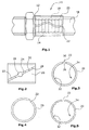
- Fig. 1 shows a clamping fitting 10 in the assembled state.
- the clamping fitting 10 has a fitting body 12, which is provided with a support sleeve 14.
- This support sleeve 14 may be profiled on its outer side and / or have a sealing element (eg O-ring).
- On the support sleeve the end 16 of a pipe 18 to be connected is pushed.
- This connection end 16 in turn is enclosed by a slotted clamping sleeve 20, which in this exemplary embodiment has a wave-shaped slot 22.
- the clamping sleeves 20 was pushed in the expanded state to the terminal end 16 of the tube 18, for which purpose a spacer 24 was inserted into the slot 22 of the clamping sleeve 20, as for example in the FIGS. 6 to 17 is shown.
- Fig. 2 shows a further embodiment of the clamping sleeve 20 with obliquely extending slot 22 and arranged in this spacer 24, which has a shape which is formed according to a widening 26 in the slot 22.
- the slot 22 is formed by flanks 28,30 of the wall of the clamping sleeve 20.
- the spacer 24 abuts the flanks 28,30 and keeps them at a distance, ie the clamping sleeve 20 in the expanded state.
- FIGS. 3 to 5 show various embodiments of the slot 22.
- the slot 22 in the clamping sleeve 20 of Fig. 3 essentially aligned radially and has substantially mutually parallel flanks 28,30.
- the slot 22 extends at an angle to the radial extent of the clamping sleeve 20.
- the slot 22 is widened outwards.
- the show FIGS. 3 and 4 different surface contours 32 on the inner side 34 of the clamping sleeve 20. In this way, increased safety of the clamping sleeve 20 against axial displacements relative to the terminal end 16 of the tube 18 can be achieved.
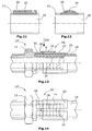
- FIGS. 6 to 10 different spacers 24 are shown for maintaining the expansion of the clamping sleeve 20.
- the spacer 24 is shown with a rectangular cross-section.
- Fig. 7 10 shows a round-outline spacer 24 and a handle 36 for gripping the spacer 24 by means of a tool to remove the spacer 24 from the slot 22.
- Fig. 8 shows a spacer 24 with wedge-shaped portion 38 whose wedge shape is adapted to the wedge shape of the slot 22.
- the spacers 24 each have spring properties.
- FIGS. 11 and 12 For example, two collets 20 are shown with spacers 24 disposed in their slots 22 which have recesses 36 in the form of cutouts in this embodiment which allow tools to be used to pull the spacers 24 out of the slots 22.
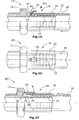
- FIGS. 13 and 14 an embodiment of a clamping fitting 10 'is shown, in which the spacer 24 of the clamping sleeve 20 is automatically removed when the clamping sleeve 20 is pushed over the terminal end 16 of the tube 18 and the support sleeve 14.
- a Auswerfervorsprung 39 is formed on the fitting body 12, against which an inclined surface 40 of the spacer 24 abuts when the clamping sleeve 20 is pushed in the direction of Aufwerfervorsprungs 39.
- Fig. 14 shows the situation or the construction of this clamp fitting 10 'in the direction of arrow 14 of Fig. 13 ,
- FIGS. 15 and 16 there is described a clamp fitting 10 "not in accordance with the invention in which the spacer 24 is ejected from the pipe 18 when the pipe 18 is near its maximum insertion position, the spacer 24 having a trigger portion 42 which is inserted into the annular space 44 the ferrule 20 and the support sleeve 14.
- the end face 46 of the terminal end 16 of the tube 18 then presses against the release portion 42 of the spacer 24, which thus "out” out of the slot of the sleeve 20 outwards.
- Fig. 17 shows a not belonging to the invention clamping fitting 10, wherein the clamping sleeve 20 is held in the expanded state on the fitting body 12.
- the fitting body 12 has a ring recess 48 which is open towards the free end of the support sleeve 14 and the clamping sleeve 20 surrounds by clamping.
- the spacer 24 In the slot of the clamping sleeve 20 is the spacer 24, which has a rounding 50 on its underside facing the support sleeve 14. In this rounding, the spacer 24 protrudes into the annular space 44 between the clamping sleeve 20 and the support sleeve 14.
- the front side 46 of the tube 18 now presses when inserting the tube from below over the rounding 50 against the spacer 24, so that it turns out of the slot to the outside, the clamping sleeve 20 thus releases and the clamping sleeve 20 thus their clamping force on the terminal end 16th of the tube 18 can exercise.
Landscapes
- Engineering & Computer Science (AREA)
- General Engineering & Computer Science (AREA)
- Mechanical Engineering (AREA)
- Clamps And Clips (AREA)
- Quick-Acting Or Multi-Walled Pipe Joints (AREA)
Abstract
Claims (11)
- Raccord à serrage pour un tuyau, en particulier un tuyau en plastique ou un tuyau composite plastique/métal, comprenant- un corps de raccord (12) qui présente une douille d'appui (14) sur laquelle une extrémité (16) d'un tuyau à raccorder (18) peut être enfilée, et- une douille de serrage (20) présentant une paroi, et qui présente une fente (22) s'étendant entre ses extrémités axiales et délimitée par des flancs opposés (28, 30) de la paroi et qui peut être écartée, la douille de serrage (20) entourant la douille d'appui (14) et l'extrémité (16) du tuyau à raccorder (18) lorsqu'elle est enfilée sur la douille d'appui,- où, pour conserver l'état écarté de la douille de serrage (20), une pièce d'écartement (24) amovible, contre laquelle les flancs (28, 30) de la paroi de la douille de serrage (20) écartée qui délimitent la fente (22) prennent appui, est disposée dans la fente (22) de ladite douille de serrage (20),
caractérisé en ce que- le corps de raccord (12) présente un élément éjecteur (39) contre et/ou sur lequel la pièce d'écartement (24) peut bouger lors de l'enfilage de la douille de serrage (20) écartée sur l'extrémité (16) du tuyau à raccorder (18) située sur la douille d'appui afin de sortir la pièce d'écartement (24) de la fente (22). - Raccord à serrage pour un tuyau, en particulier un tuyau en plastique ou un tuyau composite plastique/métal, comprenant- un corps de raccord (12) qui présente une douille d'appui (14) sur laquelle une extrémité (16) d'un tuyau à raccorder (18) peut être enfilée, et- une douille de serrage (20) présentant une paroi, et qui présente une fente (22) s'étendant entre ses extrémités axiales et délimitée par des flancs opposés (28, 30) de la paroi et qui peut être écartée, la douille de serrage (20) entourant la douille d'appui (14) et l'extrémité (16) du tuyau à raccorder (18) lorsqu'elle est enfilée sur la douille d'appui,- où, pour conserver l'état écarté de la douille de serrage (20), une pièce d'écartement (24) amovible, contre laquelle les flancs (28, 30) de la paroi de la douille de serrage (20) écartée qui délimitent la fente (22) prennent appui, est disposée dans la fente (22) de ladite douille de serrage (20),
caractérisé en ce que- la pièce d'écartement (24) présente des organes de manipulation (36) sous forme d'évidements, qui permettent d'appliquer un outil afin d'extraire par traction la pièce d'écartement (24) de la fente (22) de la douille de serrage (20). - Raccord à serrage selon l'une des revendications 1 ou 2, caractérisé en ce que la fente (22) présente un tracé ondulatoire ou sinusoïdal le long de l'extension axiale de la douille de serrage (20).
- Raccord à serrage selon l'une des revendications 1 ou 2, caractérisé en ce que la fente (22) est réalisée comme rainure de filetage / rainure hélicoïdale.
- Raccord à serrage selon l'une des revendications 1 à 3, caractérisé en ce que la douille de serrage (20) présente une face intérieure (34) structurée.
- Raccord à serrage selon l'une des revendications 1 à 4, caractérisé en ce que la douille de serrage (20) présente un matériau et/ou la paroi de la douille de serrage (20) présente une épaisseur qui est choisi(e) de telle sorte que, après suppression d'un écartement élastique de la douille de serrage (20), celle-ci appuie l'extrémité (16) du tuyau à raccorder (18) contre la douille d'appui (14) de manière étanche et en décharge de traction.
- Raccord à serrage selon l'une des revendications 1 à 6, caractérisé en ce que la douille de serrage (20) est maintenue écartée au niveau du corps de raccord (12) en permettant une contraction lorsque la pièce d'écartement (24) est enlevée.
- Raccord à serrage selon l'une des revendications 1 à 7, caractérisé en ce que la pièce d'écartement (24) présente une partie de repérage de compression qui est située à l'extérieur de la paroi de la douille de serrage (20).
- Raccord à serrage selon l'une des revendications 1 à 8, caractérisé en ce que la douille de serrage (20) présente une structure sensiblement cylindrique, elliptique ou autre structure de type annulaire.
- Raccord à serrage selon l'une des revendications 1 à 9, caractérisé en ce qu'un contour de la fente (22) réalisé avec un angle de flanc est tel qu'une largeur de la fente s'agrandit d'une face intérieure à une face extérieure de la douille de serrage.
- Raccord à serrage selon l'une des revendications 1 à 10, caractérisé en ce que le matériau de la douille de serrage comporte un matériau superplastique, notamment un alliage à mémoire de forme.
Applications Claiming Priority (2)
| Application Number | Priority Date | Filing Date | Title |
|---|---|---|---|
| DE102007025931A DE102007025931B3 (de) | 2007-06-02 | 2007-06-02 | Klemmfitting für ein Rohr |
| PCT/EP2008/056758 WO2008148728A1 (fr) | 2007-06-02 | 2008-06-02 | Élément raccord de serrage pour un tuyau |
Publications (2)
| Publication Number | Publication Date |
|---|---|
| EP2150743A1 EP2150743A1 (fr) | 2010-02-10 |
| EP2150743B1 true EP2150743B1 (fr) | 2012-06-13 |
Family
ID=39869795
Family Applications (1)
| Application Number | Title | Priority Date | Filing Date |
|---|---|---|---|
| EP08760345A Active EP2150743B1 (fr) | 2007-06-02 | 2008-06-02 | Element raccord de serrage pour un tuyau |
Country Status (5)
| Country | Link |
|---|---|
| US (1) | US8226127B2 (fr) |
| EP (1) | EP2150743B1 (fr) |
| DE (1) | DE102007025931B3 (fr) |
| ES (1) | ES2388693T3 (fr) |
| WO (1) | WO2008148728A1 (fr) |
Families Citing this family (11)
| Publication number | Priority date | Publication date | Assignee | Title |
|---|---|---|---|---|
| US8196615B1 (en) * | 2008-04-21 | 2012-06-12 | Jim Browarny | Liquid/air pressure testing tool |
| JP4906973B1 (ja) * | 2011-03-22 | 2012-03-28 | 井上スダレ株式会社 | 管継手 |
| JP5998592B2 (ja) * | 2011-07-21 | 2016-09-28 | 三菱樹脂株式会社 | 留め具及びキャップの接続構造 |
| ITMI20120819A1 (it) * | 2012-05-11 | 2013-11-12 | Le Silerchie S A S Di Adriano Galb Iati & C | Elemento di bloccaggio di una camicia di copertura attorno a un tubo, nonche' utensile a pinza e metodo per l'applicazione dell' elemento di bloccaggio stesso |
| EP2669563A1 (fr) | 2012-06-01 | 2013-12-04 | Uponor Innovation AB | Raccord de tuyau |
| CL2013003210A1 (es) * | 2013-11-08 | 2014-07-25 | Thc Chile S A | Sistema de conexion para conectar una tuberia pex con un fitting que incluye una abrazadera definida por dos paredes curvas, una articulacion flexible, medios de enganche, una pestaña anular dispuesta en una region interna de dichas paredes curvas y medios de desenganche que permiten desconectar los medios de enganche. |
| US9732776B2 (en) * | 2014-10-10 | 2017-08-15 | The Boeing Company | Marman clamp with a shape memory alloy actuator |
| DE102015114116A1 (de) * | 2015-08-26 | 2017-03-02 | Dr. Ing. H.C. F. Porsche Aktiengesellschaft | Rohrverbinder zum Anschließen einer Kraftstoffleitung einer Kraftstoffversorgung für ein Kraftfahrzeugmotor |
| DE102015122345A1 (de) * | 2015-12-21 | 2017-06-22 | Rehau Ag + Co. | Schiebehülse, Schiebehülsenverbindung sowie Verfahren zur Herstellung einer Schiebehülsenverbindung |
| DE102015122346A1 (de) * | 2015-12-21 | 2017-06-22 | Rehau Ag + Co. | Schiebehülse, Schiebehülsenverbindung sowie Verfahren zur Herstellung einer Schiebehülsenverbindung |
| US12504106B1 (en) | 2024-06-24 | 2025-12-23 | Goodrich Corporation | Low clearance fluid coupling |
Citations (1)
| Publication number | Priority date | Publication date | Assignee | Title |
|---|---|---|---|---|
| DE19902265A1 (de) * | 1999-01-21 | 2000-09-21 | Brugg Rohrsysteme Gmbh | Zweiteiliger Klemmverbinder für Rohre und Schläuche aus polymerem Werkstoff |
Family Cites Families (16)
| Publication number | Priority date | Publication date | Assignee | Title |
|---|---|---|---|---|
| US4005884A (en) | 1972-06-21 | 1977-02-01 | Mordechai Drori | Pipe coupling |
| FR2525304B1 (fr) | 1982-04-19 | 1988-04-08 | Alsthom Atlantique | Dispositif de securite d'antidevissage |
| EP0122485B1 (fr) | 1983-03-19 | 1987-09-02 | Nec Corporation | Antenne à deux éléments repliés |
| US4635966A (en) | 1985-09-20 | 1987-01-13 | Chrysler Motors Corporation | Hose connector |
| DE3911406A1 (de) * | 1989-04-07 | 1990-10-11 | Kirchner Fraenk Rohr | Zweiteiliger metallischer klemmverbinder fuer rohre und schlaeuche aus polymerem werkstoff |
| JPH05231571A (ja) | 1992-02-17 | 1993-09-07 | Sekisui Chem Co Ltd | 管継手 |
| GB2286027B (en) | 1994-01-31 | 1997-07-09 | Victaulic Plc | Improvements in and relating to pipe couplings |
| DE19518628C1 (de) * | 1995-05-20 | 1996-09-26 | Rasmussen Gmbh | Haltevorrichtung zur Lagesicherung einer Schlauchschelle |
| EP0849519A1 (fr) * | 1995-10-21 | 1998-06-24 | DaimlerChrysler Aerospace Airbus Gesellschaft mit beschränkter Haftung | Elément de fixation pour fixation de tuyaux flexibles de protection |
| US5915739A (en) | 1997-08-12 | 1999-06-29 | Acd Tridon Inc. | Clamp retention device |
| US5930872A (en) * | 1997-09-22 | 1999-08-03 | The Gates Corporation | Device for mounting and deploying a shrinkable clamp |
| JP3405966B2 (ja) * | 2000-02-07 | 2003-05-12 | 東尾メック株式会社 | 管継手 |
| US6701581B2 (en) | 2002-08-10 | 2004-03-09 | Epicor Industries, Inc. | Clamp retention device |
| US7090255B2 (en) * | 2004-05-26 | 2006-08-15 | Atco Products, Inc. | Disposable clamp locator for air conditioning hose assemblies |
| DE202004017433U1 (de) | 2004-11-10 | 2005-10-20 | Gebrüder Beul GmbH & Co. KG | Steckverbinder für den Rohrleitungsbau |
| JP3754059B1 (ja) | 2004-11-29 | 2006-03-08 | 井上スダレ株式会社 | 管継手 |
-
2007
- 2007-06-02 DE DE102007025931A patent/DE102007025931B3/de active Active
-
2008
- 2008-06-02 ES ES08760345T patent/ES2388693T3/es active Active
- 2008-06-02 US US12/602,603 patent/US8226127B2/en not_active Expired - Fee Related
- 2008-06-02 WO PCT/EP2008/056758 patent/WO2008148728A1/fr not_active Ceased
- 2008-06-02 EP EP08760345A patent/EP2150743B1/fr active Active
Patent Citations (1)
| Publication number | Priority date | Publication date | Assignee | Title |
|---|---|---|---|---|
| DE19902265A1 (de) * | 1999-01-21 | 2000-09-21 | Brugg Rohrsysteme Gmbh | Zweiteiliger Klemmverbinder für Rohre und Schläuche aus polymerem Werkstoff |
Also Published As
| Publication number | Publication date |
|---|---|
| EP2150743A1 (fr) | 2010-02-10 |
| WO2008148728A1 (fr) | 2008-12-11 |
| US20100194099A1 (en) | 2010-08-05 |
| ES2388693T3 (es) | 2012-10-17 |
| DE102007025931B3 (de) | 2009-01-15 |
| US8226127B2 (en) | 2012-07-24 |
Similar Documents
| Publication | Publication Date | Title |
|---|---|---|
| EP2150743B1 (fr) | Element raccord de serrage pour un tuyau | |
| EP1912007B1 (fr) | Collier de serrage | |
| DE3424675C2 (de) | Schlauchkupplung | |
| EP1852643B1 (fr) | Collier destiné à la fixation d'un objet tubulaire | |
| DE19828059C2 (de) | Anschlußarmatur mit einem durch Schlitze in Haltezungen aufgeteilten Befestigungsvorsprung | |
| DE10032010C1 (de) | Anschlußarmatur mit elastischem Ring als Anschlag | |
| DE19740144C2 (de) | Verbindung eines Metallrohres mit einer Metallhülse, sowie Verfahren zur Herstellung der Verbindung | |
| DE102016103703A1 (de) | Profilschelle | |
| EP2025988B1 (fr) | Raccord pour un tuyau, en particulier un tuyau en plastique ou un tuyau composite en plastique et métal | |
| EP2647896A2 (fr) | Agencement de connexion pour une liaison à brides conique et liaison à brides conique | |
| DE2750547C2 (de) | Anschlußvorrichtung für halbstarre Rohre | |
| DE29921406U1 (de) | Steckarmatur zum schnellen und lösbaren Anschluß von Druckmittel-Leitungen | |
| DE2822259C2 (de) | Schnellkupplung für rohrförmige Leitungen, insbesondere für Flüssigkeiten | |
| EP1930605A1 (fr) | Raccord pour tuyau, en particulier tuyau en plastique ou composite de métal / plastique | |
| DE202007007827U1 (de) | Klemmfitting für ein Rohr | |
| DE102018205891B3 (de) | Durch Fluidbeaufschlagung aktivierbare Betätigungseinrichtung mit Rastmechanismus | |
| EP2446980B1 (fr) | Tuyau d'échafaudage et procédé destiné au traitement d'extrémités de tuyaux | |
| EP2679272B1 (fr) | Dispositif de trocart | |
| EP1740873B1 (fr) | Raccord pour tuyaux flexibles | |
| EP1412117B1 (fr) | Element d'ecartement pour une pince de serrage et pince de serrage | |
| DE29811259U1 (de) | Anschlußarmatur mit einem durch Schlitze in Haltezungen aufgeteilten Befestigungsvorsprung | |
| DE29807763U1 (de) | Anschlußvorrichtung zum schnellen und lösbaren Anschluß von Rohrleitungen | |
| DE29704444U1 (de) | Anschlußvorrichtung für Sanitär-Rohrleitungen | |
| DE10324581B3 (de) | Spreizniet | |
| DE3047382A1 (de) | "rohrverbindung" |
Legal Events
| Date | Code | Title | Description |
|---|---|---|---|
| PUAI | Public reference made under article 153(3) epc to a published international application that has entered the european phase |
Free format text: ORIGINAL CODE: 0009012 |
|
| 17P | Request for examination filed |
Effective date: 20091126 |
|
| AK | Designated contracting states |
Kind code of ref document: A1 Designated state(s): AT BE BG CH CY CZ DE DK EE ES FI FR GB GR HR HU IE IS IT LI LT LU LV MC MT NL NO PL PT RO SE SI SK TR |
|
| AX | Request for extension of the european patent |
Extension state: AL BA MK RS |
|
| 17Q | First examination report despatched |
Effective date: 20100616 |
|
| DAX | Request for extension of the european patent (deleted) | ||
| GRAP | Despatch of communication of intention to grant a patent |
Free format text: ORIGINAL CODE: EPIDOSNIGR1 |
|
| GRAS | Grant fee paid |
Free format text: ORIGINAL CODE: EPIDOSNIGR3 |
|
| GRAA | (expected) grant |
Free format text: ORIGINAL CODE: 0009210 |
|
| RBV | Designated contracting states (corrected) |
Designated state(s): AT BE BG CH CY CZ DK EE ES FI FR GB GR HR HU IE IS IT LI LT LU LV MC MT NL NO PL PT RO SE SI SK TR |
|
| REG | Reference to a national code |
Ref country code: DE Ref legal event code: R108 |
|
| AK | Designated contracting states |
Kind code of ref document: B1 Designated state(s): AT BE BG CH CY CZ DK EE ES FI FR GB GR HR HU IE IS IT LI LT LU LV MC MT NL NO PL PT RO SE SI SK TR |
|
| REG | Reference to a national code |
Ref country code: GB Ref legal event code: FG4D Free format text: NOT ENGLISH |
|
| REG | Reference to a national code |
Ref country code: AT Ref legal event code: REF Ref document number: 562154 Country of ref document: AT Kind code of ref document: T Effective date: 20120615 Ref country code: CH Ref legal event code: EP |
|
| REG | Reference to a national code |
Ref country code: IE Ref legal event code: FG4D Free format text: LANGUAGE OF EP DOCUMENT: GERMAN |
|
| REG | Reference to a national code |
Ref country code: DE Ref legal event code: R108 Effective date: 20120530 |
|
| REG | Reference to a national code |
Ref country code: NL Ref legal event code: T3 |
|
| REG | Reference to a national code |
Ref country code: ES Ref legal event code: FG2A Ref document number: 2388693 Country of ref document: ES Kind code of ref document: T3 Effective date: 20121017 |
|
| PG25 | Lapsed in a contracting state [announced via postgrant information from national office to epo] |
Ref country code: SE Free format text: LAPSE BECAUSE OF FAILURE TO SUBMIT A TRANSLATION OF THE DESCRIPTION OR TO PAY THE FEE WITHIN THE PRESCRIBED TIME-LIMIT Effective date: 20120613 Ref country code: CY Free format text: LAPSE BECAUSE OF FAILURE TO SUBMIT A TRANSLATION OF THE DESCRIPTION OR TO PAY THE FEE WITHIN THE PRESCRIBED TIME-LIMIT Effective date: 20120613 Ref country code: LT Free format text: LAPSE BECAUSE OF FAILURE TO SUBMIT A TRANSLATION OF THE DESCRIPTION OR TO PAY THE FEE WITHIN THE PRESCRIBED TIME-LIMIT Effective date: 20120613 Ref country code: NO Free format text: LAPSE BECAUSE OF FAILURE TO SUBMIT A TRANSLATION OF THE DESCRIPTION OR TO PAY THE FEE WITHIN THE PRESCRIBED TIME-LIMIT Effective date: 20120913 Ref country code: FI Free format text: LAPSE BECAUSE OF FAILURE TO SUBMIT A TRANSLATION OF THE DESCRIPTION OR TO PAY THE FEE WITHIN THE PRESCRIBED TIME-LIMIT Effective date: 20120613 |
|
| REG | Reference to a national code |
Ref country code: LT Ref legal event code: MG4D Effective date: 20120613 |
|
| PG25 | Lapsed in a contracting state [announced via postgrant information from national office to epo] |
Ref country code: LV Free format text: LAPSE BECAUSE OF FAILURE TO SUBMIT A TRANSLATION OF THE DESCRIPTION OR TO PAY THE FEE WITHIN THE PRESCRIBED TIME-LIMIT Effective date: 20120613 Ref country code: GR Free format text: LAPSE BECAUSE OF FAILURE TO SUBMIT A TRANSLATION OF THE DESCRIPTION OR TO PAY THE FEE WITHIN THE PRESCRIBED TIME-LIMIT Effective date: 20120914 Ref country code: HR Free format text: LAPSE BECAUSE OF FAILURE TO SUBMIT A TRANSLATION OF THE DESCRIPTION OR TO PAY THE FEE WITHIN THE PRESCRIBED TIME-LIMIT Effective date: 20120613 Ref country code: SI Free format text: LAPSE BECAUSE OF FAILURE TO SUBMIT A TRANSLATION OF THE DESCRIPTION OR TO PAY THE FEE WITHIN THE PRESCRIBED TIME-LIMIT Effective date: 20120613 |
|
| RAP2 | Party data changed (patent owner data changed or rights of a patent transferred) |
Owner name: UPONOR INNOVATION AB |
|
| PG25 | Lapsed in a contracting state [announced via postgrant information from national office to epo] |
Ref country code: EE Free format text: LAPSE BECAUSE OF FAILURE TO SUBMIT A TRANSLATION OF THE DESCRIPTION OR TO PAY THE FEE WITHIN THE PRESCRIBED TIME-LIMIT Effective date: 20120613 Ref country code: IS Free format text: LAPSE BECAUSE OF FAILURE TO SUBMIT A TRANSLATION OF THE DESCRIPTION OR TO PAY THE FEE WITHIN THE PRESCRIBED TIME-LIMIT Effective date: 20121013 Ref country code: CZ Free format text: LAPSE BECAUSE OF FAILURE TO SUBMIT A TRANSLATION OF THE DESCRIPTION OR TO PAY THE FEE WITHIN THE PRESCRIBED TIME-LIMIT Effective date: 20120613 Ref country code: RO Free format text: LAPSE BECAUSE OF FAILURE TO SUBMIT A TRANSLATION OF THE DESCRIPTION OR TO PAY THE FEE WITHIN THE PRESCRIBED TIME-LIMIT Effective date: 20120613 Ref country code: SK Free format text: LAPSE BECAUSE OF FAILURE TO SUBMIT A TRANSLATION OF THE DESCRIPTION OR TO PAY THE FEE WITHIN THE PRESCRIBED TIME-LIMIT Effective date: 20120613 |
|
| PG25 | Lapsed in a contracting state [announced via postgrant information from national office to epo] |
Ref country code: PT Free format text: LAPSE BECAUSE OF FAILURE TO SUBMIT A TRANSLATION OF THE DESCRIPTION OR TO PAY THE FEE WITHIN THE PRESCRIBED TIME-LIMIT Effective date: 20121015 Ref country code: PL Free format text: LAPSE BECAUSE OF FAILURE TO SUBMIT A TRANSLATION OF THE DESCRIPTION OR TO PAY THE FEE WITHIN THE PRESCRIBED TIME-LIMIT Effective date: 20120613 |
|
| PLBE | No opposition filed within time limit |
Free format text: ORIGINAL CODE: 0009261 |
|
| STAA | Information on the status of an ep patent application or granted ep patent |
Free format text: STATUS: NO OPPOSITION FILED WITHIN TIME LIMIT |
|
| PG25 | Lapsed in a contracting state [announced via postgrant information from national office to epo] |
Ref country code: DK Free format text: LAPSE BECAUSE OF FAILURE TO SUBMIT A TRANSLATION OF THE DESCRIPTION OR TO PAY THE FEE WITHIN THE PRESCRIBED TIME-LIMIT Effective date: 20120613 |
|
| 26N | No opposition filed |
Effective date: 20130314 |
|
| PG25 | Lapsed in a contracting state [announced via postgrant information from national office to epo] |
Ref country code: BG Free format text: LAPSE BECAUSE OF FAILURE TO SUBMIT A TRANSLATION OF THE DESCRIPTION OR TO PAY THE FEE WITHIN THE PRESCRIBED TIME-LIMIT Effective date: 20120913 |
|
| BERE | Be: lapsed |
Owner name: UPONOR INNOVATION A.B. Effective date: 20130630 |
|
| PG25 | Lapsed in a contracting state [announced via postgrant information from national office to epo] |
Ref country code: MC Free format text: LAPSE BECAUSE OF FAILURE TO SUBMIT A TRANSLATION OF THE DESCRIPTION OR TO PAY THE FEE WITHIN THE PRESCRIBED TIME-LIMIT Effective date: 20120613 |
|
| REG | Reference to a national code |
Ref country code: CH Ref legal event code: PL |
|
| REG | Reference to a national code |
Ref country code: IE Ref legal event code: MM4A |
|
| PG25 | Lapsed in a contracting state [announced via postgrant information from national office to epo] |
Ref country code: BE Free format text: LAPSE BECAUSE OF NON-PAYMENT OF DUE FEES Effective date: 20130630 |
|
| PG25 | Lapsed in a contracting state [announced via postgrant information from national office to epo] |
Ref country code: CH Free format text: LAPSE BECAUSE OF NON-PAYMENT OF DUE FEES Effective date: 20130630 Ref country code: LI Free format text: LAPSE BECAUSE OF NON-PAYMENT OF DUE FEES Effective date: 20130630 Ref country code: IE Free format text: LAPSE BECAUSE OF NON-PAYMENT OF DUE FEES Effective date: 20130602 |
|
| REG | Reference to a national code |
Ref country code: AT Ref legal event code: MM01 Ref document number: 562154 Country of ref document: AT Kind code of ref document: T Effective date: 20130602 |
|
| PG25 | Lapsed in a contracting state [announced via postgrant information from national office to epo] |
Ref country code: AT Free format text: LAPSE BECAUSE OF NON-PAYMENT OF DUE FEES Effective date: 20130602 |
|
| PG25 | Lapsed in a contracting state [announced via postgrant information from national office to epo] |
Ref country code: MT Free format text: LAPSE BECAUSE OF FAILURE TO SUBMIT A TRANSLATION OF THE DESCRIPTION OR TO PAY THE FEE WITHIN THE PRESCRIBED TIME-LIMIT Effective date: 20120613 |
|
| PG25 | Lapsed in a contracting state [announced via postgrant information from national office to epo] |
Ref country code: TR Free format text: LAPSE BECAUSE OF FAILURE TO SUBMIT A TRANSLATION OF THE DESCRIPTION OR TO PAY THE FEE WITHIN THE PRESCRIBED TIME-LIMIT Effective date: 20120613 |
|
| PG25 | Lapsed in a contracting state [announced via postgrant information from national office to epo] |
Ref country code: HU Free format text: LAPSE BECAUSE OF FAILURE TO SUBMIT A TRANSLATION OF THE DESCRIPTION OR TO PAY THE FEE WITHIN THE PRESCRIBED TIME-LIMIT; INVALID AB INITIO Effective date: 20080602 Ref country code: LU Free format text: LAPSE BECAUSE OF NON-PAYMENT OF DUE FEES Effective date: 20130602 |
|
| REG | Reference to a national code |
Ref country code: FR Ref legal event code: PLFP Year of fee payment: 9 |
|
| REG | Reference to a national code |
Ref country code: FR Ref legal event code: PLFP Year of fee payment: 10 |
|
| REG | Reference to a national code |
Ref country code: FR Ref legal event code: PLFP Year of fee payment: 11 |
|
| PGFP | Annual fee paid to national office [announced via postgrant information from national office to epo] |
Ref country code: NL Payment date: 20190619 Year of fee payment: 12 |
|
| PGFP | Annual fee paid to national office [announced via postgrant information from national office to epo] |
Ref country code: ES Payment date: 20190719 Year of fee payment: 12 |
|
| REG | Reference to a national code |
Ref country code: NL Ref legal event code: MM Effective date: 20200701 |
|
| PG25 | Lapsed in a contracting state [announced via postgrant information from national office to epo] |
Ref country code: NL Free format text: LAPSE BECAUSE OF NON-PAYMENT OF DUE FEES Effective date: 20200701 |
|
| REG | Reference to a national code |
Ref country code: ES Ref legal event code: FD2A Effective date: 20211026 |
|
| PG25 | Lapsed in a contracting state [announced via postgrant information from national office to epo] |
Ref country code: ES Free format text: LAPSE BECAUSE OF NON-PAYMENT OF DUE FEES Effective date: 20200603 |
|
| PGFP | Annual fee paid to national office [announced via postgrant information from national office to epo] |
Ref country code: IT Payment date: 20220628 Year of fee payment: 15 |
|
| PGFP | Annual fee paid to national office [announced via postgrant information from national office to epo] |
Ref country code: FR Payment date: 20220628 Year of fee payment: 15 |
|
| PG25 | Lapsed in a contracting state [announced via postgrant information from national office to epo] |
Ref country code: FR Free format text: LAPSE BECAUSE OF NON-PAYMENT OF DUE FEES Effective date: 20230630 |
|
| PG25 | Lapsed in a contracting state [announced via postgrant information from national office to epo] |
Ref country code: IT Free format text: LAPSE BECAUSE OF NON-PAYMENT OF DUE FEES Effective date: 20230602 |
|
| PGFP | Annual fee paid to national office [announced via postgrant information from national office to epo] |
Ref country code: GB Payment date: 20250618 Year of fee payment: 18 |