EP2151207A2 - Élément élastique pour l'usage dans un dispositif de stabilisation pour des os et la méthode de fabrication d'un tel élément élastique - Google Patents
Élément élastique pour l'usage dans un dispositif de stabilisation pour des os et la méthode de fabrication d'un tel élément élastique Download PDFInfo
- Publication number
- EP2151207A2 EP2151207A2 EP09014615A EP09014615A EP2151207A2 EP 2151207 A2 EP2151207 A2 EP 2151207A2 EP 09014615 A EP09014615 A EP 09014615A EP 09014615 A EP09014615 A EP 09014615A EP 2151207 A2 EP2151207 A2 EP 2151207A2
- Authority
- EP
- European Patent Office
- Prior art keywords
- elastic element
- elastic
- bone
- rod
- elastic member
- Prior art date
- Legal status (The legal status is an assumption and is not a legal conclusion. Google has not performed a legal analysis and makes no representation as to the accuracy of the status listed.)
- Granted
Links
- 210000000988 bone and bone Anatomy 0.000 title claims abstract description 56
- 238000004519 manufacturing process Methods 0.000 title claims abstract description 12
- 230000003019 stabilising effect Effects 0.000 title 1
- 238000000034 method Methods 0.000 claims abstract description 13
- 230000006641 stabilisation Effects 0.000 claims abstract description 11
- 238000011105 stabilization Methods 0.000 claims abstract description 11
- 238000004873 anchoring Methods 0.000 claims description 17
- 230000000087 stabilizing effect Effects 0.000 claims description 13
- 230000003628 erosive effect Effects 0.000 claims description 9
- 238000003754 machining Methods 0.000 claims description 7
- RTAQQCXQSZGOHL-UHFFFAOYSA-N Titanium Chemical compound [Ti] RTAQQCXQSZGOHL-UHFFFAOYSA-N 0.000 claims description 5
- 229910052719 titanium Inorganic materials 0.000 claims description 5
- 239000010936 titanium Substances 0.000 claims description 5
- 239000000560 biocompatible material Substances 0.000 claims description 4
- XLYOFNOQVPJJNP-UHFFFAOYSA-N water Substances O XLYOFNOQVPJJNP-UHFFFAOYSA-N 0.000 claims description 4
- 230000015572 biosynthetic process Effects 0.000 claims description 2
- 238000004804 winding Methods 0.000 claims description 2
- 238000005452 bending Methods 0.000 description 10
- 230000008878 coupling Effects 0.000 description 6
- 238000010168 coupling process Methods 0.000 description 6
- 238000005859 coupling reaction Methods 0.000 description 6
- 230000004048 modification Effects 0.000 description 5
- 238000012986 modification Methods 0.000 description 5
- 230000001419 dependent effect Effects 0.000 description 4
- 210000002414 leg Anatomy 0.000 description 4
- 230000008901 benefit Effects 0.000 description 3
- 230000006835 compression Effects 0.000 description 2
- 238000007906 compression Methods 0.000 description 2
- 238000010276 construction Methods 0.000 description 2
- 230000007423 decrease Effects 0.000 description 2
- 208000014674 injury Diseases 0.000 description 2
- CNQCVBJFEGMYDW-UHFFFAOYSA-N lawrencium atom Chemical compound [Lr] CNQCVBJFEGMYDW-UHFFFAOYSA-N 0.000 description 2
- 239000000463 material Substances 0.000 description 2
- 238000001356 surgical procedure Methods 0.000 description 2
- 230000007704 transition Effects 0.000 description 2
- 230000008733 trauma Effects 0.000 description 2
- 208000010392 Bone Fractures Diseases 0.000 description 1
- 238000013459 approach Methods 0.000 description 1
- 238000013461 design Methods 0.000 description 1
- 238000011161 development Methods 0.000 description 1
- 230000018109 developmental process Effects 0.000 description 1
- 210000000629 knee joint Anatomy 0.000 description 1
- 210000004705 lumbosacral region Anatomy 0.000 description 1
- 238000003801 milling Methods 0.000 description 1
- 239000007787 solid Substances 0.000 description 1
- 239000003381 stabilizer Substances 0.000 description 1
- 210000000707 wrist Anatomy 0.000 description 1
Images






Classifications
-
- A—HUMAN NECESSITIES
- A61—MEDICAL OR VETERINARY SCIENCE; HYGIENE
- A61B—DIAGNOSIS; SURGERY; IDENTIFICATION
- A61B17/00—Surgical instruments, devices or methods
- A61B17/56—Surgical instruments or methods for treatment of bones or joints; Devices specially adapted therefor
- A61B17/58—Surgical instruments or methods for treatment of bones or joints; Devices specially adapted therefor for osteosynthesis, e.g. bone plates, screws or setting implements
- A61B17/68—Internal fixation devices, including fasteners and spinal fixators, even if a part thereof projects from the skin
- A61B17/70—Spinal positioners or stabilisers, e.g. stabilisers comprising fluid filler in an implant
- A61B17/7001—Screws or hooks combined with longitudinal elements which do not contact vertebrae
- A61B17/7032—Screws or hooks with U-shaped head or back through which longitudinal rods pass
-
- F—MECHANICAL ENGINEERING; LIGHTING; HEATING; WEAPONS; BLASTING
- F21—LIGHTING
- F21K—NON-ELECTRIC LIGHT SOURCES USING LUMINESCENCE; LIGHT SOURCES USING ELECTROCHEMILUMINESCENCE; LIGHT SOURCES USING CHARGES OF COMBUSTIBLE MATERIAL; LIGHT SOURCES USING SEMICONDUCTOR DEVICES AS LIGHT-GENERATING ELEMENTS; LIGHT SOURCES NOT OTHERWISE PROVIDED FOR
- F21K9/00—Light sources using semiconductor devices as light-generating elements, e.g. using light-emitting diodes [LED] or lasers
- F21K9/20—Light sources comprising attachment means
- F21K9/23—Retrofit light sources for lighting devices with a single fitting for each light source, e.g. for substitution of incandescent lamps with bayonet or threaded fittings
- F21K9/238—Arrangement or mounting of circuit elements integrated in the light source
-
- A—HUMAN NECESSITIES
- A61—MEDICAL OR VETERINARY SCIENCE; HYGIENE
- A61B—DIAGNOSIS; SURGERY; IDENTIFICATION
- A61B17/00—Surgical instruments, devices or methods
- A61B17/56—Surgical instruments or methods for treatment of bones or joints; Devices specially adapted therefor
- A61B17/58—Surgical instruments or methods for treatment of bones or joints; Devices specially adapted therefor for osteosynthesis, e.g. bone plates, screws or setting implements
- A61B17/68—Internal fixation devices, including fasteners and spinal fixators, even if a part thereof projects from the skin
- A61B17/70—Spinal positioners or stabilisers, e.g. stabilisers comprising fluid filler in an implant
- A61B17/7001—Screws or hooks combined with longitudinal elements which do not contact vertebrae
- A61B17/7002—Longitudinal elements, e.g. rods
-
- A—HUMAN NECESSITIES
- A61—MEDICAL OR VETERINARY SCIENCE; HYGIENE
- A61B—DIAGNOSIS; SURGERY; IDENTIFICATION
- A61B17/00—Surgical instruments, devices or methods
- A61B17/56—Surgical instruments or methods for treatment of bones or joints; Devices specially adapted therefor
- A61B17/58—Surgical instruments or methods for treatment of bones or joints; Devices specially adapted therefor for osteosynthesis, e.g. bone plates, screws or setting implements
- A61B17/68—Internal fixation devices, including fasteners and spinal fixators, even if a part thereof projects from the skin
- A61B17/70—Spinal positioners or stabilisers, e.g. stabilisers comprising fluid filler in an implant
- A61B17/7001—Screws or hooks combined with longitudinal elements which do not contact vertebrae
- A61B17/7002—Longitudinal elements, e.g. rods
- A61B17/7004—Longitudinal elements, e.g. rods with a cross-section which varies along its length
-
- A—HUMAN NECESSITIES
- A61—MEDICAL OR VETERINARY SCIENCE; HYGIENE
- A61B—DIAGNOSIS; SURGERY; IDENTIFICATION
- A61B17/00—Surgical instruments, devices or methods
- A61B17/56—Surgical instruments or methods for treatment of bones or joints; Devices specially adapted therefor
- A61B17/58—Surgical instruments or methods for treatment of bones or joints; Devices specially adapted therefor for osteosynthesis, e.g. bone plates, screws or setting implements
- A61B17/68—Internal fixation devices, including fasteners and spinal fixators, even if a part thereof projects from the skin
- A61B17/70—Spinal positioners or stabilisers, e.g. stabilisers comprising fluid filler in an implant
- A61B17/7001—Screws or hooks combined with longitudinal elements which do not contact vertebrae
- A61B17/7002—Longitudinal elements, e.g. rods
- A61B17/7019—Longitudinal elements having flexible parts, or parts connected together, such that after implantation the elements can move relative to each other
- A61B17/7026—Longitudinal elements having flexible parts, or parts connected together, such that after implantation the elements can move relative to each other with a part that is flexible due to its form
- A61B17/7028—Longitudinal elements having flexible parts, or parts connected together, such that after implantation the elements can move relative to each other with a part that is flexible due to its form the flexible part being a coil spring
-
- A—HUMAN NECESSITIES
- A61—MEDICAL OR VETERINARY SCIENCE; HYGIENE
- A61B—DIAGNOSIS; SURGERY; IDENTIFICATION
- A61B17/00—Surgical instruments, devices or methods
- A61B17/56—Surgical instruments or methods for treatment of bones or joints; Devices specially adapted therefor
- A61B17/58—Surgical instruments or methods for treatment of bones or joints; Devices specially adapted therefor for osteosynthesis, e.g. bone plates, screws or setting implements
- A61B17/68—Internal fixation devices, including fasteners and spinal fixators, even if a part thereof projects from the skin
- A61B17/70—Spinal positioners or stabilisers, e.g. stabilisers comprising fluid filler in an implant
- A61B17/7001—Screws or hooks combined with longitudinal elements which do not contact vertebrae
- A61B17/7035—Screws or hooks, wherein a rod-clamping part and a bone-anchoring part can pivot relative to each other
- A61B17/7037—Screws or hooks, wherein a rod-clamping part and a bone-anchoring part can pivot relative to each other wherein pivoting is blocked when the rod is clamped
-
- A—HUMAN NECESSITIES
- A61—MEDICAL OR VETERINARY SCIENCE; HYGIENE
- A61B—DIAGNOSIS; SURGERY; IDENTIFICATION
- A61B17/00—Surgical instruments, devices or methods
- A61B17/56—Surgical instruments or methods for treatment of bones or joints; Devices specially adapted therefor
- A61B17/58—Surgical instruments or methods for treatment of bones or joints; Devices specially adapted therefor for osteosynthesis, e.g. bone plates, screws or setting implements
- A61B17/68—Internal fixation devices, including fasteners and spinal fixators, even if a part thereof projects from the skin
- A61B17/70—Spinal positioners or stabilisers, e.g. stabilisers comprising fluid filler in an implant
- A61B17/7059—Cortical plates
-
- A—HUMAN NECESSITIES
- A61—MEDICAL OR VETERINARY SCIENCE; HYGIENE
- A61B—DIAGNOSIS; SURGERY; IDENTIFICATION
- A61B17/00—Surgical instruments, devices or methods
- A61B17/56—Surgical instruments or methods for treatment of bones or joints; Devices specially adapted therefor
- A61B17/58—Surgical instruments or methods for treatment of bones or joints; Devices specially adapted therefor for osteosynthesis, e.g. bone plates, screws or setting implements
- A61B17/68—Internal fixation devices, including fasteners and spinal fixators, even if a part thereof projects from the skin
- A61B17/84—Fasteners therefor or fasteners being internal fixation devices
- A61B17/86—Pins or screws or threaded wires; nuts therefor
- A61B17/8625—Shanks, i.e. parts contacting bone tissue
-
- B—PERFORMING OPERATIONS; TRANSPORTING
- B23—MACHINE TOOLS; METAL-WORKING NOT OTHERWISE PROVIDED FOR
- B23C—MILLING
- B23C3/00—Milling particular work; Special milling operations; Machines therefor
- B23C3/28—Grooving workpieces
- B23C3/32—Milling helical grooves, e.g. in making twist-drills
-
- B—PERFORMING OPERATIONS; TRANSPORTING
- B23—MACHINE TOOLS; METAL-WORKING NOT OTHERWISE PROVIDED FOR
- B23H—WORKING OF METAL BY THE ACTION OF A HIGH CONCENTRATION OF ELECTRIC CURRENT ON A WORKPIECE USING AN ELECTRODE WHICH TAKES THE PLACE OF A TOOL; SUCH WORKING COMBINED WITH OTHER FORMS OF WORKING OF METAL
- B23H7/00—Processes or apparatus applicable to both electrical discharge machining and electrochemical machining
- B23H7/02—Wire-cutting
-
- B—PERFORMING OPERATIONS; TRANSPORTING
- B23—MACHINE TOOLS; METAL-WORKING NOT OTHERWISE PROVIDED FOR
- B23P—METAL-WORKING NOT OTHERWISE PROVIDED FOR; COMBINED OPERATIONS; UNIVERSAL MACHINE TOOLS
- B23P13/00—Making metal objects by operations essentially involving machining but not covered by a single other subclass
- B23P13/02—Making metal objects by operations essentially involving machining but not covered by a single other subclass in which only the machining operations are important
-
- F—MECHANICAL ENGINEERING; LIGHTING; HEATING; WEAPONS; BLASTING
- F16—ENGINEERING ELEMENTS AND UNITS; GENERAL MEASURES FOR PRODUCING AND MAINTAINING EFFECTIVE FUNCTIONING OF MACHINES OR INSTALLATIONS; THERMAL INSULATION IN GENERAL
- F16F—SPRINGS; SHOCK-ABSORBERS; MEANS FOR DAMPING VIBRATION
- F16F1/00—Springs
- F16F1/02—Springs made of steel or other material having low internal friction; Wound, torsion, leaf, cup, ring or the like springs, the material of the spring not being relevant
- F16F1/04—Wound springs
-
- F—MECHANICAL ENGINEERING; LIGHTING; HEATING; WEAPONS; BLASTING
- F21—LIGHTING
- F21V—FUNCTIONAL FEATURES OR DETAILS OF LIGHTING DEVICES OR SYSTEMS THEREOF; STRUCTURAL COMBINATIONS OF LIGHTING DEVICES WITH OTHER ARTICLES, NOT OTHERWISE PROVIDED FOR
- F21V17/00—Fastening of component parts of lighting devices, e.g. shades, globes, refractors, reflectors, filters, screens, grids or protective cages
- F21V17/10—Fastening of component parts of lighting devices, e.g. shades, globes, refractors, reflectors, filters, screens, grids or protective cages characterised by specific fastening means or way of fastening
- F21V17/104—Fastening of component parts of lighting devices, e.g. shades, globes, refractors, reflectors, filters, screens, grids or protective cages characterised by specific fastening means or way of fastening using feather joints, e.g. tongues and grooves, with or without friction
-
- A—HUMAN NECESSITIES
- A61—MEDICAL OR VETERINARY SCIENCE; HYGIENE
- A61B—DIAGNOSIS; SURGERY; IDENTIFICATION
- A61B17/00—Surgical instruments, devices or methods
- A61B17/56—Surgical instruments or methods for treatment of bones or joints; Devices specially adapted therefor
- A61B17/58—Surgical instruments or methods for treatment of bones or joints; Devices specially adapted therefor for osteosynthesis, e.g. bone plates, screws or setting implements
- A61B17/68—Internal fixation devices, including fasteners and spinal fixators, even if a part thereof projects from the skin
- A61B17/70—Spinal positioners or stabilisers, e.g. stabilisers comprising fluid filler in an implant
- A61B17/7062—Devices acting on, attached to, or simulating the effect of, vertebral processes, vertebral facets or ribs ; Tools for such devices
-
- A—HUMAN NECESSITIES
- A61—MEDICAL OR VETERINARY SCIENCE; HYGIENE
- A61B—DIAGNOSIS; SURGERY; IDENTIFICATION
- A61B17/00—Surgical instruments, devices or methods
- A61B17/56—Surgical instruments or methods for treatment of bones or joints; Devices specially adapted therefor
- A61B17/58—Surgical instruments or methods for treatment of bones or joints; Devices specially adapted therefor for osteosynthesis, e.g. bone plates, screws or setting implements
- A61B17/68—Internal fixation devices, including fasteners and spinal fixators, even if a part thereof projects from the skin
- A61B17/84—Fasteners therefor or fasteners being internal fixation devices
- A61B17/86—Pins or screws or threaded wires; nuts therefor
- A61B17/866—Material or manufacture
-
- A—HUMAN NECESSITIES
- A61—MEDICAL OR VETERINARY SCIENCE; HYGIENE
- A61B—DIAGNOSIS; SURGERY; IDENTIFICATION
- A61B17/00—Surgical instruments, devices or methods
- A61B2017/00526—Methods of manufacturing
-
- A—HUMAN NECESSITIES
- A61—MEDICAL OR VETERINARY SCIENCE; HYGIENE
- A61B—DIAGNOSIS; SURGERY; IDENTIFICATION
- A61B17/00—Surgical instruments, devices or methods
- A61B2017/00831—Material properties
- A61B2017/00862—Material properties elastic or resilient
-
- A—HUMAN NECESSITIES
- A61—MEDICAL OR VETERINARY SCIENCE; HYGIENE
- A61F—FILTERS IMPLANTABLE INTO BLOOD VESSELS; PROSTHESES; DEVICES PROVIDING PATENCY TO, OR PREVENTING COLLAPSING OF, TUBULAR STRUCTURES OF THE BODY, e.g. STENTS; ORTHOPAEDIC, NURSING OR CONTRACEPTIVE DEVICES; FOMENTATION; TREATMENT OR PROTECTION OF EYES OR EARS; BANDAGES, DRESSINGS OR ABSORBENT PADS; FIRST-AID KITS
- A61F2/00—Filters implantable into blood vessels; Prostheses, i.e. artificial substitutes or replacements for parts of the body; Appliances for connecting them with the body; Devices providing patency to, or preventing collapsing of, tubular structures of the body, e.g. stents
- A61F2/02—Prostheses implantable into the body
- A61F2/30—Joints
- A61F2/44—Joints for the spine, e.g. vertebrae, spinal discs
- A61F2/4455—Joints for the spine, e.g. vertebrae, spinal discs for the fusion of spinal bodies, e.g. intervertebral fusion of adjacent spinal bodies, e.g. fusion cages
-
- F—MECHANICAL ENGINEERING; LIGHTING; HEATING; WEAPONS; BLASTING
- F16—ENGINEERING ELEMENTS AND UNITS; GENERAL MEASURES FOR PRODUCING AND MAINTAINING EFFECTIVE FUNCTIONING OF MACHINES OR INSTALLATIONS; THERMAL INSULATION IN GENERAL
- F16F—SPRINGS; SHOCK-ABSORBERS; MEANS FOR DAMPING VIBRATION
- F16F1/00—Springs
- F16F1/02—Springs made of steel or other material having low internal friction; Wound, torsion, leaf, cup, ring or the like springs, the material of the spring not being relevant
- F16F1/04—Wound springs
- F16F1/042—Wound springs characterised by the cross-section of the wire
- F16F1/043—Wound springs characterised by the cross-section of the wire the cross-section varying with the wire length
-
- F—MECHANICAL ENGINEERING; LIGHTING; HEATING; WEAPONS; BLASTING
- F21—LIGHTING
- F21Y—INDEXING SCHEME ASSOCIATED WITH SUBCLASSES F21K, F21L, F21S and F21V, RELATING TO THE FORM OR THE KIND OF THE LIGHT SOURCES OR OF THE COLOUR OF THE LIGHT EMITTED
- F21Y2113/00—Combination of light sources
- F21Y2113/10—Combination of light sources of different colours
- F21Y2113/13—Combination of light sources of different colours comprising an assembly of point-like light sources
-
- F—MECHANICAL ENGINEERING; LIGHTING; HEATING; WEAPONS; BLASTING
- F21—LIGHTING
- F21Y—INDEXING SCHEME ASSOCIATED WITH SUBCLASSES F21K, F21L, F21S and F21V, RELATING TO THE FORM OR THE KIND OF THE LIGHT SOURCES OR OF THE COLOUR OF THE LIGHT EMITTED
- F21Y2115/00—Light-generating elements of semiconductor light sources
- F21Y2115/10—Light-emitting diodes [LED]
-
- Y—GENERAL TAGGING OF NEW TECHNOLOGICAL DEVELOPMENTS; GENERAL TAGGING OF CROSS-SECTIONAL TECHNOLOGIES SPANNING OVER SEVERAL SECTIONS OF THE IPC; TECHNICAL SUBJECTS COVERED BY FORMER USPC CROSS-REFERENCE ART COLLECTIONS [XRACs] AND DIGESTS
- Y10—TECHNICAL SUBJECTS COVERED BY FORMER USPC
- Y10T—TECHNICAL SUBJECTS COVERED BY FORMER US CLASSIFICATION
- Y10T29/00—Metal working
- Y10T29/49—Method of mechanical manufacture
- Y10T29/49995—Shaping one-piece blank by removing material
-
- Y—GENERAL TAGGING OF NEW TECHNOLOGICAL DEVELOPMENTS; GENERAL TAGGING OF CROSS-SECTIONAL TECHNOLOGIES SPANNING OVER SEVERAL SECTIONS OF THE IPC; TECHNICAL SUBJECTS COVERED BY FORMER USPC CROSS-REFERENCE ART COLLECTIONS [XRACs] AND DIGESTS
- Y10—TECHNICAL SUBJECTS COVERED BY FORMER USPC
- Y10T—TECHNICAL SUBJECTS COVERED BY FORMER US CLASSIFICATION
- Y10T409/00—Gear cutting, milling, or planing
- Y10T409/30—Milling
- Y10T409/303752—Process
Definitions
- the invention relates to an elastic element for use in spinal or trauma surgery, a bone anchoring element, a rod-shaped element and a stabilizing device each having such an elastic element, and a manufacturing method for such an elastic element.
- fixation and stabilization devices consist of at least two anchored in the bone or vertebrae and connected via a plate or a rod bone screws.
- Such rigid systems do not allow movement of the relatively fixed bone parts or vertebrae.
- dynamic stabilization is desirable in which the bone parts and vertebrae to be stabilized can perform a controlled limited movement towards each other.
- the dynamic stabilizing device is the use of a resilient element instead of a rigid rod connecting the bone anchoring elements.
- a dynamic stabilizing device for vertebrae which comprises a first and a second screw to be anchored in the vertebrae each having a receiving part for inserting a spring connecting the screws and such a spring.
- the spring itself is formed as a whole in the form of a coil spring with closely adjacent turns in the manner of a tension spring and is fixed by clamping screws in the receiving parts.
- Another disadvantage of the device is that the elasticity of the spring with otherwise identical spring properties depends on the length of the spring. Furthermore, the bending stiffness of the spring is relatively low, especially for short lengths.
- fixation device for a joint, eg for a wrist or a knee joint, known in which a connected at its ends with bone anchoring elements fixation rod is formed in two parts, wherein the two parts of the fixation rod are connected to each other via a flexible coupling part and wherein the fixation rods to the Coupling part are mounted outside of the body.
- the two parts of the fixation rod are not fixedly connected to the coupling part, but can move freely along a bore in the coupling part.
- the diameter of the coupling part is due to the nature of the connection with the two-piece fixation rod always larger than the diameter of the fixation rod.
- This known fixation device is not suitable because of its complicated and voluminous structure for internal use on the spine or other bones. In particular, the realization of such a flexible coupling part with high bending stiffness requires a large volume of construction.
- the object is achieved by an elastic element according to claim 1 and a method for producing such an elastic element according to claim 15.
- the invention has the advantage that an elastic element is formed at the same time compact and with high bending stiffness. This is particularly important for applications on the spinal column and there especially on the cervical spine, where the available space is significantly lower compared to applications on the lumbar spine.
- an elastic element can optionally be combined with rigid rod-shaped elements of different lengths to form an elastic rod-shaped element or combined with different shafts and / or heads to form a bone screw with elastic properties.
- the elastic rod-shaped element or the bone screw then have, depending on the elastic element used predetermined elastic properties such as a certain compression and extension ability in the axial direction, and a certain bending and torsional rigidity.
- the elastic element can be connected with rod-shaped components of different thickness or with plates of different shape and length to be used in spine and / or trauma surgery.
- Fig. 1 an elastic element 1 according to a first embodiment is shown.
- the elastic element 1 is formed as a hollow cylindrical member having a continuous coaxial bore 2 and a first recess 3 running helically with a predetermined pitch and over a predetermined length in the direction of the cylinder axis in the wall, which opens into the bore 2 in the radial direction. Further, spirally with the same pitch as the first recess 3 is the same Length in the direction of the cylinder axis M in the wall between the turns of the first recess 3, a second recess 4 is provided, which opens into the bore 2 in the radial direction.
- a double helical spring is formed from two helical springs, wherein the turns of the one helical spring extend between the turns of the second helical spring.
- the turns of a coil spring are rotated relative to the turns of the other coil spring about its common center axis by 180 °, so that the first and the second recess are exactly opposite.
- the length L of the spiral recesses 3, 4 in the direction of the cylinder axis, the height H of the recesses, the pitch ⁇ of the helical lines, along which the recesses 3, 4 are formed, and the diameter D1 of the coaxial bore 2 are chosen such that a desired stiffness of the elastic member against axial forces F ax , bending forces F B and torsional forces F T , which act on the elastic member is given.
- the elastic element 1 Adjacent to its two free ends, the elastic element 1 in each case has a section with an inner thread 5, 5 'extending over a predetermined length. The internal thread portions do not overlap in the axial direction with the portion in which the recesses are formed in the wall.
- the outer diameter of the elastic element 1 is selected according to the respective application.
- the elastic element is formed of a body-friendly material such as titanium.
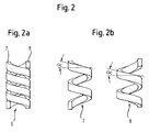
- Fig. 2 illustrates the construction of a double helical spring 6 as shown by the recesses 3, 4 in the elastic element in Fig. 1 is formed.
- the twin coil spring 6 is composed of two coil springs 7 and 8.
- the two coil springs 7 and 8 are identical and in particular have an identical pitch ⁇ , but the first coil spring 7 in the double helical spring 6 relative to the second coil spring 8 about their common center axis Turned 180 °.
- the turns of the first coil spring 7 extend in the double helical spring 6 therefore in the middle between the turns of the second coil spring 8 and vice versa.
- the pitch of the coil spring is limited by the fact that at least one entire turn must be present in order to obtain good elasticity properties.
- a twin coil spring less than a full turn is required for each of the coil springs to obtain good elasticity properties. Therefore, with the same length, the pitch of the coil spring can be increased as compared with a single coil spring. An increase in the pitch of the coil spring results in the same length and the same other properties increase the flexural rigidity. Therefore, it is possible with a twin helical spring compared to a single helical spring with the same dimensions to achieve a higher bending stiffness.
- Fig. 3 is shown an elastic element 11 according to a second embodiment.
- the elastic member 11 according to a second embodiment is different from the elastic member 1 according to a first embodiment in that instead of extending from the first to the second end 17 'of the elastic member extending bore 2 is provided adjacent to the first end 17 of the elastic element blind bore 12.
- the blind bore extends over the entire length L of the double helical spring, which is formed as in the first embodiment by a first and a second recess 13 and 14 in the wall of a hollow cylindrical portion. Adjacent to the first end 17, an internal thread 15 is provided in the blind bore.
- the elastic element has a cylindrical projection 16 with an external thread.
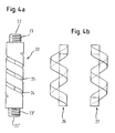
- Fig. 4 is shown an elastic element according to a third embodiment.
- the elastic member 20 according to the third embodiment differs from the other embodiments in that no hole coaxial with the center axis M of the elastic member 20 is provided. Furthermore, a cylindrical projection 23, 23 'with an external thread is provided adjacent both the first end 22 and the second end 22'. As in the embodiments described above, two coil springs 26, 27 are formed by two recesses 24, 25.
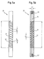
- Fig. 5a is shown an elastic element according to a fourth embodiment.
- Fig. 5b is a sectional view of the elastic element Fig. 5a ,
- the elastic member 30 according to the fourth embodiment differs from that according to the first embodiment in that the pitch ⁇ of the double helical spring forming recesses 31, 32 is not constant but over the length L of the double helical spring of the elastic member 30 varies.
- the pitch ⁇ varies such that the distance .DELTA.L of the recesses 31, 32 increases from the free ends of the elastic element 30 toward the center.
- the flexural rigidity of the elastic element 30, which increases as the distance ⁇ L of the recesses 31, 32 increases also varies.
- On the slope of the recesses along the center axis of the elastic element can thus be set specifically a specific location-dependent bending stiffness.
- the elastic member 30 has adjacent each of its two free ends a portion having a predetermined length extending internal thread 33, 33 'and a continuous coaxial bore 34 having an inner diameter D1.
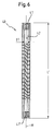
- Fig. 6 is a sectional view of an elastic member according to a fifth embodiment.
- the elastic member 40 according to the fifth embodiment is different from the elastic member 30 according to the fourth embodiment in that the inner diameter D1 of the continuous coaxial bore 42 is not constant but varies along the length L 'of the elastic member 40.
- the inner diameter D1 of the bore 42 varies in such a way that, viewed from the free ends, it decreases toward the middle of the elastic element 40. Accordingly, the flexural rigidity of the elastic member 40, which increases as the inner diameter D1 decreases, also varies. Over the inner diameter of the coaxial bore can thus specifically a specific location-dependent Flexural rigidity of the elastic member 40 can be adjusted.
- the elastic member 40 has adjacent each of its two free ends a portion with an inner thread 41, 41 'extending over a predetermined length.
- FIG. 7a an elastic element according to a sixth embodiment is shown.
- Fig. 7b is a sectional view of the elastic element Fig. 7a ,
- the elastic member 35 according to the sixth embodiment differs from that according to the fifth embodiment in that the outer diameter D2 of the elastic member 35 is not constant but varies over the length L 'de of the elastic member 35.
- the outer diameter D2 varies in such a way that, viewed from the free ends, it increases towards the middle of the elastic element 35.
- the flexural rigidity of the elastic member 35 which increases with increasing outer diameter of the elastic member, also varies. On the outer diameter of the elastic element can thus be set specifically a specific location-dependent flexural rigidity.
- the elastic member 35 has adjacent each of its two free ends a portion having a predetermined length extending internal thread 36, 36 ', a continuous coaxial bore 37 having an inner diameter D1 and two recesses 38 and 39 in the mold a coil spring through which a double helical spring is formed.
- the elastic element may include more than two coil springs, wherein the turns of a coil spring each extend between the turns of the other coil springs.
- a bore extending over the entire length of the elastic element is provided whose diameter is smaller than the outer diameter of the cylindrical projection 16.
- the fourth to sixth embodiments have each been described so that the flexural rigidity of the elastic member over the length L of the double helical spring increases from the free ends toward the center of the elastic member.
- the flexural rigidity can be adjusted with any other location dependence along the length L of the double helical spring or the length L 'of the elastic member.
- the elastic member has the shape of a cylinder or a hollow cylinder, however, the outer shape may also deviate from the exact shape of a cylinder and, for example, have an oval cross-sectional area or be formed waisted.
- the elastic element thus has a direction-dependent bending elasticity:
- the elastic rod-shaped element 50 consists of the spring element 1 and two cylindrical bar sections 51, 51 ', each having at its end a cylindrical projection, not shown, with an external thread with an internal thread 5 or 5 'of the spring element 1 cooperates.
- the rod sections 51, 51 'and the spring element 1 in this embodiment have substantially the same outer diameter.
- the length of the rod sections 51, 51 'and the spring element 1 are independently selectable with regard to a desired application.
- the elastic rod-shaped element 50 serves, for example, for connecting pedicle screws to the spinal column.
- the thus formed rod-shaped element 30 absorbs by the elastic properties of the spring element 1 to a predetermined extent compression, extension, bending and torsional forces.
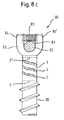
- Fig. 8b shows a second example of application of the elastic element 1.
- the elastic element 1 is here part of a bone anchoring element, which is designed as a polyaxial bone screw 60.
- the polyaxial bone screw 60 has a screw element 61, which consists of the elastic element 1, a threaded shaft 62 in this embodiment with a tip, not shown, and a screw head 63.
- the threaded shaft 62 has a bone thread 64 for screwing into the bone and a cylindrical, not shown Approach with an external thread, which cooperates with the internal thread 5 of the spring element 1.
- the screw head 63 has a cylindrical portion 65 and adjacent thereto as the threaded shaft 62 a cylindrical projection, not shown, with an external thread, which cooperates with the internal thread 5 'of the spring element 1.
- the screw member 61 is pivotally supported in a receiving part 66 in the unloaded state.
- the receiving part 66 is formed substantially cylindrical and has at its one end an axially symmetrical aligned first bore 67, whose diameter is larger than that of the threaded shaft 62 and smaller than that of the screw head 63. Further, the receiving part 66 has a coaxial second bore 68 which is open on the opposite end of the first bore 67 and whose diameter is so large that the screw member 61 can be passed through the open end with the threaded shaft 62 through the first bore 67, until the screw head 63 abuts the edge of the first bore 67.
- the receiving part 66 has a U-shaped recess 69 extending from the free end in the direction of the first bore 67, through which two free legs 70, 70 'are formed. In a region adjacent to their free end, the legs 70, 70 'on an internal thread, which cooperates with a corresponding external thread of an internal screw 71 for fixing a rod 72.
- a pressure element 73 for fixing the screw head 63 in the receiving part 66 which is formed so that it has on its side facing the screw head 63 a spherical recess 74 whose radius is substantially equal to the radius of the spherical segment portion of the screw head 63rd is.
- the outer diameter of the pressure element 73 is selected such that it is displaceable in the receiving part 66 towards the screw head 63.
- the pressure element 73 further includes a coaxial bore 75 for accessing a not-shown recess in the screw head 63 for engagement with a screw-in tool.
- the screw member 61 In operation, in the internal thread 5 of the elastic element 1 of the threaded shaft 62 is screwed with its cylindrical projection not shown and into the internal thread 5 'of the screw head 63 with its cylindrical neck, not shown, to form the screw member 61. Thereafter, the screw member 61 thus formed with the threaded shaft 62 is first inserted through the second bore 68 in the receiving part 66 until the screw head 63 abuts the edge of the first bore 67. Subsequently, the pressure element 73 is introduced with the spherical recess ahead through the second bore 68 in the receiving part 66. Then, the screw member 61 is screwed into the bone or vertebra.
- the rod 72 is inserted into the receiving part 66 between the two free legs 70, 70 ', the angular position of the receiving part is adjusted relative to the screw member and fixed with the inner screw 71.
- the elastic element movements are made possible around the rest position in a limited way.
- the spring element 1 can absorb bending forces, and tensile and compressive forces. If the elastic element, with its elastic portion formed by the coil springs, does not protrude beyond the bone surface, the screw element 61 can nevertheless yield somewhat during a movement of the bone or vertebra. This prevents unfavorable voltages from occurring.
- the polyaxial screw is not limited to the above-described embodiment, but may be any other polyaxial screw having a three-piece screw member as described above.
- the rod fixation is not on the in Fig. 8b shown limited internal screw, but it may additionally be provided an outer nut, or any known type of rod fixing can be used.
- a bone anchoring element is shown, which is designed as a monoaxial screw 80.
- the screw head is formed as a receiving part 81.
- a U-shaped recess 83 is provided adjacent to the first free end of the receiving part 81.
- the free legs 84, 84 'formed by the U-shaped recess have on their inside an internal thread into which the external thread of an internal screw 85 engages.
- the rod 82 is clamped in the assembled state of the monoaxial screw between the bottom of the U-shaped recess 83 and the inner screw 85.
- a non-illustrated cylindrical projection is provided with an external thread, which engages in the adjacent to the first end of the elastic member 1 internal thread 5.
- the monoaxial screw Adjacent to the end opposite the first end of the elastic portion 1, the monoaxial screw has a threaded shaft 86 which, like the above-described threaded shaft 62 of the polyaxial bone screw 60 is formed and engages with a cylindrical projection, not shown, with an external thread in the internal thread 5 'of the elastic element 1.
- the threaded shaft 86 and the receiving part are screwed into the two internal threads 5, 5 'of the elastic element 1. Subsequently, the monoaxial screw 80 is screwed into the bone or the vertebra. Then, the U-shaped recess 83 is aligned and the rod 82 is inserted. Finally, the rod 82 is fixed with the inner screw 85.
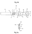
- a connecting element 90 which consists of a rod-shaped portion 91, a spring element 1 and a plate 92.
- the rod-shaped portion 91 has a cylindrical projection, not shown, with an external thread for screwing into the adjacent to the one end of the spring element 1 internal thread 5.
- the plate 92 has a cylindrical projection, not shown, with an external thread for screwing into the adjoining the other end of the spring element 1 internal thread 5 '.
- the plate consists of two circular in plan view sections 93, 93 ', which are interconnected via a web portion 94.
- the width B of the web portion 94 is smaller than the diameter D of the circular portions 93, 93 '.
- Coaxial with the circular sections are provided two bores 95, 95 'for countersunk screws through the plate.
- the first side 96 of the plate has a convex curvature while the second side 97 of the plate has a concave curvature for abutment of this side of a bone. Due to the different radii of curvature of the two sides 96, 97 of the plate 92, the plate 92 tapers to the lateral edges 98, 98 'out. This allows the plate to be stable and at the same time space-saving.
- the rod-shaped element 50, the polyaxial bone screw 60, the monoaxial screw 80 and the connecting element 90 has been described so that the elastic element 1 is formed as a separate part and is screwed to the other parts.
- the elastic element according to the invention as a portion of a one-piece rod-shaped element, a one-piece screw member, a one-piece monoaxial screw and a one-piece connecting element is formed with a rod and a plate portion.
- a stabilization device 100 is shown for the spine, wherein two bone anchoring elements 101, 101 'and an elastic rod-shaped element 103 connecting them is provided.
- the screw elements 102, 102 'of the bone anchoring elements 101 and 101' and the elastic rod-shaped element 103 each have an inventive elastic element 1.
- the two screw elements 102, 102 ' are screwed into vertebrae 103, 103', so that a dynamic stabilization is produced between these vertebrae via the stabilization device 100.
- the stabilizing device need not necessarily include bone anchoring elements with a resilient element and a rod-shaped element with the resilient element. Depending on the field of application, it is also possible to provide only a rod-shaped element with an elastic element and bone anchoring elements without an elastic element with rigid screw elements.
- an elastic element 1 by means of wire erosion is in a solid cylinder of a biocompatible material such.
- a biocompatible material such as titanium, perpendicular to the center axis of the cylinder through the entire cylinder extending first bore 110 is generated.
- a second bore 111 is formed coaxially with the center axis of the cylinder over its entire length, so that a hollow cylinder 112 is formed.
- the order of forming the first and second bores is arbitrary and may be reversed.
- a wire 113 is cut through the first hole 110 for wire eroding carried out.
- Fig. 10a indicates this process step by an arrow P.
- wire EDM 113 is performed while the hollow cylinder 112 is displaced along the center axis in the direction X at a constant feed rate relative to the wire and simultaneously rotated at a constant angular velocity about its center axis.
- the rotation is in Fig. 10b indicated by an arrow D. It depends solely on a relative movement between the wire and the hollow cylinder. So either the wire can be fixed in space and the hollow cylinder to be moved or vice versa.
- Fig. 10c shows the elastic element just before the end of the wire EDM step. After the recesses are formed in the axial direction over a predetermined length, the feed and the rotation of the hollow cylinder is stopped.
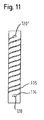
- a semi-circular outlet 120, 120 'formed As in Fig. 11 shown at the beginning of the wire erosion and at the end of the wire erosion in each case a semi-circular outlet 120, 120 'formed.
- the shape of the spout 120 or 120 'does not necessarily have the shape of a semicircle, but may also have any other arbitrary shape, such as that of another circular section, through the load spikes in the material at the transition from the flexible section to the fixed section during operation being held.
- an internal thread 5, 5 ' is formed in the two end sections of the coaxial bore adjoining the two ends along the center axis.
- the elastic element 1 can also be produced by means of milling. This is again based on a cylinder with a predetermined outer diameter of a biocompatible material, such as titanium, and milled with a thin disc cutter along a first helix, the main axis collinear to the main axis of the cylinder is a first recess. Then, in a second step, a further recess is formed along a second helix whose turns run between the turns of the first helix. Subsequently, along the main axis of the cylinder over the entire length of the cylinder, a bore is formed such that the recesses open into this bore.
- a biocompatible material such as titanium
- the outlet of the spiral at the transition between the spiral portion and the end portion of the elastic member has a great influence on the stability of the elastic element 1. Therefore, with a router bit the spout of the spiral at both ends of the spiral is post-processed such that the sharp edge the inside of the hole is removed. For this purpose, the spout is milled with an end mill at an angle tangential to the spiral contour. Subsequently, the component is deburred inside and outside.
- an internal thread 5, 5 ' is respectively formed in the two end sections of the coaxial bore along the center axis.
- a cylindrical projection with an external thread is formed by turning.
- the diameter of the bore 111 must be smaller than the diameter of the cylindrical neck.
- the spring element according to the second and third embodiments is produced without a through hole 111.
- a first aspect relates to an elastic element (1,11,21,30,35,40) for use in a bone or vertebra stabilizing device (100) which is designed as a substantially cylindrical body having a first end (9,17,22 ) and a second end (9 ', 17', 22 ') opposite thereto and formed with an elastic portion between the first and second ends, the elastic one Section is formed of at least two coil springs, which are coaxially arranged such that the turns (3) of a coil spring (7) extends at least in a portion of the coil spring between the turns (4) of another coil spring (8).
- the elastic element (1,11,21,30,35,40) provided according to a second aspect corresponds to the first aspect, wherein the coil springs have the same outer diameter.
- the elastic element provided according to a third aspect corresponds to the first or second aspect, wherein the coil springs (7,8) in a plane containing the center axis of the coil springs (7,8) have the same cross section of the winding (3,4) ,
- the elastic element (1,11,21,30,35,40) provided according to a fourth aspect corresponds to the elastic element according to one of the first to third aspects, but with two substantially identical coil springs, each of the two coil springs (7,8 ) is rotated relative to the other about its common center axis by 180 °.
- the elastic element (1,30,35,40) provided according to a fifth aspect corresponds to the elastic element according to one of the first to fourth aspects, wherein in the elastic element coaxial with the center axis (M) has a through bore (2,34,37, 42) extending from the first end (9) to the second end (9 ') of the cylindrical body.
- the elastic member (35, 40) provided in a sixth aspect corresponds to the elastic member according to the fifth aspect, wherein the diameter (D1) of the through hole (37, 42) varies along the center axis (M).
- the elastic element (1,11,21,30,35,40) provided according to a seventh aspect corresponds to the elastic element according to one of the first to sixth aspects, wherein the elastic element consists of a biocompatible material, in particular titanium.
- the elastic element (1,11,21,30,35,40) provided according to an eighth aspect corresponds to the elastic element according to one of the first to seventh aspects, wherein adjacent to the first end a first cylindrical projection (16,23,23 ' ) with an external thread or a first bore with an internal thread (5, 15, 33, 36, 41) is provided for connection to a shaft (62) or to a head (63) of a bone screw (61), for connection to a rod section (51) or for connection to a plate (92).
- the elastic element (1,11,21,30,35,40) provided in accordance with a ninth aspect corresponds to that of the eighth apsis, adjacent to the second end (22 ') a second cylindrical projection (23') with an external thread or a male thread second bore having an internal thread (5 ', 15', 33 ', 36', 41 ') is provided for connecting to a shaft (62) or with a head (63) of a bone screw (61), for connecting to a rod portion ( 51 ') or for connection to a plate (92).
- the elastic member (35) provided according to a tenth aspect corresponds to the elastic member of any one of the first to ninth aspects, in which the outer diameter (D2) of the elastic member varies along the center axis (M).
- the elastic member (30, 35, 40) provided in accordance with an eleventh aspect corresponds to the elastic member according to any one of the first to tenth aspects, in which the pitch ( ⁇ ) of the at least two coil springs (31, 32) varies along the center axis (M) ,
- a bone anchoring element 60,80,101,101 '
- a stem 62,86
- an elastic member (1) according to any one of the first to eleventh aspects integrally formed or is formed in several pieces.
- a rod-shaped member (50) for connecting two bone anchoring members (60,80,101,101 ') is provided with an elastic member (1,11,21,30,35,40) according to any one of the first to eleventh aspects; and a rigid rod portion (51, 51 ') adjoining the one end of the elastic member (1, 11, 21, 30, 35, 40), the rod-shaped member being formed either in one piece or in a plural piece.
- a method of manufacturing an elastic member (1,11,21 comprising the steps of: (a) providing a cylindrical body (112); (b) forming a first recess (114) from outside into the cylindrical body (112) along a first helix; and (c) forming at least one further second recess (115) from outside into the cylindrical body (112) along a second helical line, the turns of the second helix extending at least in a portion between the turns of the first helix.
- a sixteenth aspect there is provided a method according to the fifteenth aspect, wherein the formation of the recesses (114, 115) is performed by wire eroding, water jet machining, laser beam machining or a machining method.
- a seventeenth aspect there is provided a method according to the fifteenth or sixteenth aspect, wherein the generation of the first and second recesses (114, 115) in steps (b) and (c) is simultaneous.
Landscapes
- Health & Medical Sciences (AREA)
- Orthopedic Medicine & Surgery (AREA)
- Surgery (AREA)
- Life Sciences & Earth Sciences (AREA)
- Neurology (AREA)
- Engineering & Computer Science (AREA)
- General Health & Medical Sciences (AREA)
- Biomedical Technology (AREA)
- Heart & Thoracic Surgery (AREA)
- Medical Informatics (AREA)
- Molecular Biology (AREA)
- Animal Behavior & Ethology (AREA)
- Nuclear Medicine, Radiotherapy & Molecular Imaging (AREA)
- Public Health (AREA)
- Veterinary Medicine (AREA)
- General Engineering & Computer Science (AREA)
- Mechanical Engineering (AREA)
- Chemical & Material Sciences (AREA)
- Chemical Kinetics & Catalysis (AREA)
- Electrochemistry (AREA)
- Physics & Mathematics (AREA)
- Microelectronics & Electronic Packaging (AREA)
- Optics & Photonics (AREA)
- Surgical Instruments (AREA)
- Springs (AREA)
Applications Claiming Priority (3)
| Application Number | Priority Date | Filing Date | Title |
|---|---|---|---|
| US56324104P | 2004-04-16 | 2004-04-16 | |
| DE200410018621 DE102004018621B4 (de) | 2004-04-16 | 2004-04-16 | Elastisches Element zur Verwendung in Stabilisierungseinrichtungen für Knochen oder Wirbel und Herstellungsverfahren für ein solches elastisches Element |
| EP05008060A EP1586276B1 (fr) | 2004-04-16 | 2005-04-13 | Dispositif de stabilisation pour des os et la méthode de fabrication d'un élément élastique |
Related Parent Applications (2)
| Application Number | Title | Priority Date | Filing Date |
|---|---|---|---|
| EP05008060.5 Division | 2005-04-13 | ||
| EP05008060A Division EP1586276B1 (fr) | 2004-04-16 | 2005-04-13 | Dispositif de stabilisation pour des os et la méthode de fabrication d'un élément élastique |
Publications (3)
| Publication Number | Publication Date |
|---|---|
| EP2151207A2 true EP2151207A2 (fr) | 2010-02-10 |
| EP2151207A3 EP2151207A3 (fr) | 2010-03-31 |
| EP2151207B1 EP2151207B1 (fr) | 2012-03-07 |
Family
ID=34935100
Family Applications (2)
| Application Number | Title | Priority Date | Filing Date |
|---|---|---|---|
| EP05008060A Expired - Lifetime EP1586276B1 (fr) | 2004-04-16 | 2005-04-13 | Dispositif de stabilisation pour des os et la méthode de fabrication d'un élément élastique |
| EP09014615A Expired - Lifetime EP2151207B1 (fr) | 2004-04-16 | 2005-04-13 | Élément élastique pour l'usage dans un dispositif de stabilisation pour des os et la méthode de fabrication d'un tel élément élastique |
Family Applications Before (1)
| Application Number | Title | Priority Date | Filing Date |
|---|---|---|---|
| EP05008060A Expired - Lifetime EP1586276B1 (fr) | 2004-04-16 | 2005-04-13 | Dispositif de stabilisation pour des os et la méthode de fabrication d'un élément élastique |
Country Status (6)
| Country | Link |
|---|---|
| US (4) | US7833256B2 (fr) |
| EP (2) | EP1586276B1 (fr) |
| JP (1) | JP4444151B2 (fr) |
| KR (1) | KR100847329B1 (fr) |
| DE (1) | DE502005008576D1 (fr) |
| ES (2) | ES2383851T3 (fr) |
Families Citing this family (223)
| Publication number | Priority date | Publication date | Assignee | Title |
|---|---|---|---|---|
| US7717958B2 (en) * | 2000-02-16 | 2010-05-18 | Trans1, Inc. | Prosthetic nucleus apparatus |
| US7938836B2 (en) | 2003-10-23 | 2011-05-10 | Trans1, Inc. | Driver assembly for simultaneous axial delivery of spinal implants |
| FR2812185B1 (fr) | 2000-07-25 | 2003-02-28 | Spine Next Sa | Piece de liaison semi-rigide pour la stabilisation du rachis |
| US7833250B2 (en) | 2004-11-10 | 2010-11-16 | Jackson Roger P | Polyaxial bone screw with helically wound capture connection |
| US10258382B2 (en) | 2007-01-18 | 2019-04-16 | Roger P. Jackson | Rod-cord dynamic connection assemblies with slidable bone anchor attachment members along the cord |
| US8292926B2 (en) | 2005-09-30 | 2012-10-23 | Jackson Roger P | Dynamic stabilization connecting member with elastic core and outer sleeve |
| US7862587B2 (en) | 2004-02-27 | 2011-01-04 | Jackson Roger P | Dynamic stabilization assemblies, tool set and method |
| US10729469B2 (en) | 2006-01-09 | 2020-08-04 | Roger P. Jackson | Flexible spinal stabilization assembly with spacer having off-axis core member |
| US8353932B2 (en) | 2005-09-30 | 2013-01-15 | Jackson Roger P | Polyaxial bone anchor assembly with one-piece closure, pressure insert and plastic elongate member |
| US8876868B2 (en) | 2002-09-06 | 2014-11-04 | Roger P. Jackson | Helical guide and advancement flange with radially loaded lip |
| WO2006052796A2 (fr) | 2004-11-10 | 2006-05-18 | Jackson Roger P | Guide helicoidal et rebord de glissement comportant des prolongements cassables |
| US7621918B2 (en) | 2004-11-23 | 2009-11-24 | Jackson Roger P | Spinal fixation tool set and method |
| US6716214B1 (en) | 2003-06-18 | 2004-04-06 | Roger P. Jackson | Polyaxial bone screw with spline capture connection |
| KR100859827B1 (ko) | 2003-05-02 | 2008-09-23 | 예일 유니버시티 | 동적 척추 안정장치 |
| US7713287B2 (en) * | 2003-05-02 | 2010-05-11 | Applied Spine Technologies, Inc. | Dynamic spine stabilizer |
| US7377923B2 (en) | 2003-05-22 | 2008-05-27 | Alphatec Spine, Inc. | Variable angle spinal screw assembly |
| US8137386B2 (en) | 2003-08-28 | 2012-03-20 | Jackson Roger P | Polyaxial bone screw apparatus |
| US7776067B2 (en) | 2005-05-27 | 2010-08-17 | Jackson Roger P | Polyaxial bone screw with shank articulation pressure insert and method |
| US8814911B2 (en) | 2003-06-18 | 2014-08-26 | Roger P. Jackson | Polyaxial bone screw with cam connection and lock and release insert |
| US8257398B2 (en) | 2003-06-18 | 2012-09-04 | Jackson Roger P | Polyaxial bone screw with cam capture |
| US8377102B2 (en) | 2003-06-18 | 2013-02-19 | Roger P. Jackson | Polyaxial bone anchor with spline capture connection and lower pressure insert |
| US7766915B2 (en) | 2004-02-27 | 2010-08-03 | Jackson Roger P | Dynamic fixation assemblies with inner core and outer coil-like member |
| US7967850B2 (en) | 2003-06-18 | 2011-06-28 | Jackson Roger P | Polyaxial bone anchor with helical capture connection, insert and dual locking assembly |
| US8936623B2 (en) | 2003-06-18 | 2015-01-20 | Roger P. Jackson | Polyaxial bone screw assembly |
| US8398682B2 (en) | 2003-06-18 | 2013-03-19 | Roger P. Jackson | Polyaxial bone screw assembly |
| US20050065516A1 (en) * | 2003-09-24 | 2005-03-24 | Tae-Ahn Jahng | Method and apparatus for flexible fixation of a spine |
| US7815665B2 (en) * | 2003-09-24 | 2010-10-19 | N Spine, Inc. | Adjustable spinal stabilization system |
| US7763052B2 (en) * | 2003-12-05 | 2010-07-27 | N Spine, Inc. | Method and apparatus for flexible fixation of a spine |
| US20050203513A1 (en) * | 2003-09-24 | 2005-09-15 | Tae-Ahn Jahng | Spinal stabilization device |
| US8979900B2 (en) | 2003-09-24 | 2015-03-17 | DePuy Synthes Products, LLC | Spinal stabilization device |
| DE102004021861A1 (de) * | 2004-05-04 | 2005-11-24 | Biedermann Motech Gmbh | Flexibler Platzhalter |
| US7527638B2 (en) | 2003-12-16 | 2009-05-05 | Depuy Spine, Inc. | Methods and devices for minimally invasive spinal fixation element placement |
| US7179261B2 (en) | 2003-12-16 | 2007-02-20 | Depuy Spine, Inc. | Percutaneous access devices and bone anchor assemblies |
| US11419642B2 (en) | 2003-12-16 | 2022-08-23 | Medos International Sarl | Percutaneous access devices and bone anchor assemblies |
| US7160300B2 (en) | 2004-02-27 | 2007-01-09 | Jackson Roger P | Orthopedic implant rod reduction tool set and method |
| US8152810B2 (en) | 2004-11-23 | 2012-04-10 | Jackson Roger P | Spinal fixation tool set and method |
| US11241261B2 (en) | 2005-09-30 | 2022-02-08 | Roger P Jackson | Apparatus and method for soft spinal stabilization using a tensionable cord and releasable end structure |
| JP2007525274A (ja) | 2004-02-27 | 2007-09-06 | ロジャー・ピー・ジャクソン | 整形外科インプラントロッド整復器具セット及び方法 |
| WO2006009218A1 (fr) * | 2004-07-22 | 2006-01-26 | Nippon Telegraph And Telephone Corporation | Appareil pour obtenir des doubles valeurs de résistance stables, procédé de fabrication correspondant, film mince d’oxyde de métal et procédé de fabrication correspondant |
| US7651502B2 (en) | 2004-09-24 | 2010-01-26 | Jackson Roger P | Spinal fixation tool set and method for rod reduction and fastener insertion |
| DE102004048938B4 (de) * | 2004-10-07 | 2015-04-02 | Synthes Gmbh | Vorrichtung zur dynamischen Stabilisierung von Rückenwirbelkörpern |
| US7604655B2 (en) | 2004-10-25 | 2009-10-20 | X-Spine Systems, Inc. | Bone fixation system and method for using the same |
| WO2006047711A2 (fr) | 2004-10-25 | 2006-05-04 | Alphaspine, Inc. | Systemes de vissage pediculaire et procedes pour assembler/installer ces systemes |
| WO2006050493A2 (fr) * | 2004-11-03 | 2006-05-11 | The Regents Of The University Of Michigan | Implant biodegradable pour fusion de vertebres par procede intertransversaire |
| US8926672B2 (en) | 2004-11-10 | 2015-01-06 | Roger P. Jackson | Splay control closure for open bone anchor |
| US9168069B2 (en) | 2009-06-15 | 2015-10-27 | Roger P. Jackson | Polyaxial bone anchor with pop-on shank and winged insert with lower skirt for engaging a friction fit retainer |
| US8308782B2 (en) | 2004-11-23 | 2012-11-13 | Jackson Roger P | Bone anchors with longitudinal connecting member engaging inserts and closures for fixation and optional angulation |
| US9216041B2 (en) | 2009-06-15 | 2015-12-22 | Roger P. Jackson | Spinal connecting members with tensioned cords and rigid sleeves for engaging compression inserts |
| US8444681B2 (en) | 2009-06-15 | 2013-05-21 | Roger P. Jackson | Polyaxial bone anchor with pop-on shank, friction fit retainer and winged insert |
| US7875065B2 (en) | 2004-11-23 | 2011-01-25 | Jackson Roger P | Polyaxial bone screw with multi-part shank retainer and pressure insert |
| US9980753B2 (en) | 2009-06-15 | 2018-05-29 | Roger P Jackson | pivotal anchor with snap-in-place insert having rotation blocking extensions |
| WO2006057837A1 (fr) | 2004-11-23 | 2006-06-01 | Jackson Roger P | Structure d'accrochage pour outil de fixation spinale |
| ATE524121T1 (de) | 2004-11-24 | 2011-09-15 | Abdou Samy | Vorrichtungen zur platzierung eines orthopädischen intervertebralen implantats |
| US8197523B2 (en) * | 2005-02-15 | 2012-06-12 | Apex Biomedical Company, Llc | Bone screw for positive locking but flexible engagement to a bone |
| US8740955B2 (en) | 2005-02-15 | 2014-06-03 | Zimmer, Inc. | Bone screw with multiple thread profiles for far cortical locking and flexible engagement to a bone |
| US10076361B2 (en) | 2005-02-22 | 2018-09-18 | Roger P. Jackson | Polyaxial bone screw with spherical capture, compression and alignment and retention structures |
| US7901437B2 (en) | 2007-01-26 | 2011-03-08 | Jackson Roger P | Dynamic stabilization member with molded connection |
| US20060282080A1 (en) * | 2005-06-08 | 2006-12-14 | Accin Corporation | Vertebral facet stabilizer |
| EP1919385B1 (fr) * | 2005-07-25 | 2014-08-20 | Smith & Nephew, Inc. | Plaques polyaxiales |
| US7811309B2 (en) * | 2005-07-26 | 2010-10-12 | Applied Spine Technologies, Inc. | Dynamic spine stabilization device with travel-limiting functionality |
| US7717943B2 (en) | 2005-07-29 | 2010-05-18 | X-Spine Systems, Inc. | Capless multiaxial screw and spinal fixation assembly and method |
| DE502006002049D1 (de) * | 2005-09-13 | 2008-12-24 | Bird Biedermann Ag | Dynamische Klemmvorrichtung für Wirbelsäulenimplantat |
| US8105368B2 (en) | 2005-09-30 | 2012-01-31 | Jackson Roger P | Dynamic stabilization connecting member with slitted core and outer sleeve |
| WO2007041702A2 (fr) | 2005-10-04 | 2007-04-12 | Alphaspine, Inc. | Systeme de vis de pedicule a fonctions de verrouillage provisoire |
| US20070093813A1 (en) * | 2005-10-11 | 2007-04-26 | Callahan Ronald Ii | Dynamic spinal stabilizer |
| US20070093814A1 (en) * | 2005-10-11 | 2007-04-26 | Callahan Ronald Ii | Dynamic spinal stabilization systems |
| US20070093815A1 (en) * | 2005-10-11 | 2007-04-26 | Callahan Ronald Ii | Dynamic spinal stabilizer |
| US7704271B2 (en) | 2005-12-19 | 2010-04-27 | Abdou M Samy | Devices and methods for inter-vertebral orthopedic device placement |
| DE102006003374A1 (de) * | 2006-01-24 | 2007-07-26 | Biedermann Motech Gmbh | Verbindungsstab mit äußerem flexiblem Element |
| US8518084B2 (en) * | 2006-01-24 | 2013-08-27 | Biedermann Technologies Gmbh & Co. Kg | Connecting rod with external flexible element |
| US20070270821A1 (en) * | 2006-04-28 | 2007-11-22 | Sdgi Holdings, Inc. | Vertebral stabilizer |
| US8172882B2 (en) | 2006-06-14 | 2012-05-08 | Spartek Medical, Inc. | Implant system and method to treat degenerative disorders of the spine |
| US7666211B2 (en) * | 2006-12-28 | 2010-02-23 | Mi4Spine, Llc | Vertebral disc annular fibrosis tensioning and lengthening device |
| WO2008003047A2 (fr) * | 2006-06-28 | 2008-01-03 | Synthes (U.S.A.) | Système de fixation dynamique |
| US7766942B2 (en) * | 2006-08-31 | 2010-08-03 | Warsaw Orthopedic, Inc. | Polymer rods for spinal applications |
| US20080071273A1 (en) * | 2006-09-15 | 2008-03-20 | Hawkes David T | Dynamic Pedicle Screw System |
| EP1920722B1 (fr) * | 2006-11-10 | 2009-06-24 | BIEDERMANN MOTECH GmbH | Clou d'ancrage d'os |
| KR100797755B1 (ko) * | 2006-11-28 | 2008-01-23 | (주)메디쎄이 | 척추경 나사못 연결로드 |
| JP2010512178A (ja) | 2006-12-08 | 2010-04-22 | ロジャー・ピー・ジャクソン | 動的脊椎インプラントのためのツールシステム |
| US8475498B2 (en) | 2007-01-18 | 2013-07-02 | Roger P. Jackson | Dynamic stabilization connecting member with cord connection |
| US8366745B2 (en) | 2007-05-01 | 2013-02-05 | Jackson Roger P | Dynamic stabilization assembly having pre-compressed spacers with differential displacements |
| US7875059B2 (en) | 2007-01-18 | 2011-01-25 | Warsaw Orthopedic, Inc. | Variable stiffness support members |
| US8398690B2 (en) * | 2007-02-07 | 2013-03-19 | Apex Biomedical Company, Llc | Rotationally asymmetric bone screw |
| WO2008098206A1 (fr) | 2007-02-09 | 2008-08-14 | Altiva Corporation | Dispositif de stabilisation dynamique |
| WO2008098201A2 (fr) * | 2007-02-09 | 2008-08-14 | Altiva Corporation | Connecteur |
| US8740944B2 (en) | 2007-02-28 | 2014-06-03 | Warsaw Orthopedic, Inc. | Vertebral stabilizer |
| EP2146654A4 (fr) | 2007-03-27 | 2011-09-28 | X Spine Systems Inc | Système à vis pédiculaire configuré pour recevoir une tige droite ou courbée |
| US8053068B2 (en) * | 2007-03-29 | 2011-11-08 | Kazak Composites, Incorporated | Shape memory alloy composite material shock and vibration isolator devices |
| US10383660B2 (en) | 2007-05-01 | 2019-08-20 | Roger P. Jackson | Soft stabilization assemblies with pretensioned cords |
| US8083772B2 (en) | 2007-06-05 | 2011-12-27 | Spartek Medical, Inc. | Dynamic spinal rod assembly and method for dynamic stabilization of the spine |
| US8048115B2 (en) | 2007-06-05 | 2011-11-01 | Spartek Medical, Inc. | Surgical tool and method for implantation of a dynamic bone anchor |
| US8048121B2 (en) | 2007-06-05 | 2011-11-01 | Spartek Medical, Inc. | Spine implant with a defelction rod system anchored to a bone anchor and method |
| US8021396B2 (en) | 2007-06-05 | 2011-09-20 | Spartek Medical, Inc. | Configurable dynamic spinal rod and method for dynamic stabilization of the spine |
| US7963978B2 (en) | 2007-06-05 | 2011-06-21 | Spartek Medical, Inc. | Method for implanting a deflection rod system and customizing the deflection rod system for a particular patient need for dynamic stabilization and motion preservation spinal implantation system |
| US8114134B2 (en) * | 2007-06-05 | 2012-02-14 | Spartek Medical, Inc. | Spinal prosthesis having a three bar linkage for motion preservation and dynamic stabilization of the spine |
| US7942900B2 (en) | 2007-06-05 | 2011-05-17 | Spartek Medical, Inc. | Shaped horizontal rod for dynamic stabilization and motion preservation spinal implantation system and method |
| US8092501B2 (en) | 2007-06-05 | 2012-01-10 | Spartek Medical, Inc. | Dynamic spinal rod and method for dynamic stabilization of the spine |
| US8109970B2 (en) | 2007-06-05 | 2012-02-07 | Spartek Medical, Inc. | Deflection rod system with a deflection contouring shield for a spine implant and method |
| US8043333B2 (en) * | 2007-06-08 | 2011-10-25 | Synthes Usa, Llc | Dynamic stabilization system |
| CA2693540A1 (fr) * | 2007-08-07 | 2009-02-12 | Synthes Usa, Llc | Systeme de cable dynamique |
| US8080038B2 (en) * | 2007-08-17 | 2011-12-20 | Jmea Corporation | Dynamic stabilization device for spine |
| ES2417013T3 (es) * | 2007-10-11 | 2013-08-05 | Biedermann Technologies Gmbh & Co. Kg | Conjunto de varilla y sistema de varilla modular para la estabilización de la columna vertebral |
| US9232968B2 (en) | 2007-12-19 | 2016-01-12 | DePuy Synthes Products, Inc. | Polymeric pedicle rods and methods of manufacturing |
| US8057515B2 (en) | 2008-02-26 | 2011-11-15 | Spartek Medical, Inc. | Load-sharing anchor having a deflectable post and centering spring and method for dynamic stabilization of the spine |
| US8083775B2 (en) * | 2008-02-26 | 2011-12-27 | Spartek Medical, Inc. | Load-sharing bone anchor having a natural center of rotation and method for dynamic stabilization of the spine |
| US8333792B2 (en) | 2008-02-26 | 2012-12-18 | Spartek Medical, Inc. | Load-sharing bone anchor having a deflectable post and method for dynamic stabilization of the spine |
| US8097024B2 (en) * | 2008-02-26 | 2012-01-17 | Spartek Medical, Inc. | Load-sharing bone anchor having a deflectable post and method for stabilization of the spine |
| US8267979B2 (en) | 2008-02-26 | 2012-09-18 | Spartek Medical, Inc. | Load-sharing bone anchor having a deflectable post and axial spring and method for dynamic stabilization of the spine |
| US8016861B2 (en) | 2008-02-26 | 2011-09-13 | Spartek Medical, Inc. | Versatile polyaxial connector assembly and method for dynamic stabilization of the spine |
| US8337536B2 (en) * | 2008-02-26 | 2012-12-25 | Spartek Medical, Inc. | Load-sharing bone anchor having a deflectable post with a compliant ring and method for stabilization of the spine |
| US8211155B2 (en) | 2008-02-26 | 2012-07-03 | Spartek Medical, Inc. | Load-sharing bone anchor having a durable compliant member and method for dynamic stabilization of the spine |
| US20100030224A1 (en) | 2008-02-26 | 2010-02-04 | Spartek Medical, Inc. | Surgical tool and method for connecting a dynamic bone anchor and dynamic vertical rod |
| DE602008004213D1 (de) * | 2008-05-06 | 2011-02-10 | Biedermann Motech Gmbh | Stangenförmiges Implantat, insbesondere zur dynamischen Stabilisierung der Wirbelsäule |
| JP5608642B2 (ja) * | 2008-05-13 | 2014-10-15 | ストライカー・スピン | 複合脊椎ロッド |
| ES2375526T3 (es) * | 2008-06-19 | 2012-03-01 | Biedermann Motech Gmbh | Conjunto de anclaje óseo. |
| US20090326584A1 (en) * | 2008-06-27 | 2009-12-31 | Michael Andrew Slivka | Spinal Dynamic Stabilization Rods Having Interior Bumpers |
| WO2010147639A1 (fr) | 2008-08-01 | 2010-12-23 | Jackson Roger P | Élément longitudinal de liaison avec cordons tendus gainés |
| US9339320B2 (en) | 2008-09-02 | 2016-05-17 | Bhdl Holdings, Llc | Modular pedicle screw system with tap and screw driver device |
| US8137384B2 (en) * | 2008-09-02 | 2012-03-20 | Bhdl Holdings, Llc | Modular pedicle screw system |
| US9408649B2 (en) * | 2008-09-11 | 2016-08-09 | Innovasis, Inc. | Radiolucent screw with radiopaque marker |
| US8292934B2 (en) | 2008-10-17 | 2012-10-23 | Warsaw Orthopedic, Inc. | Dynamic anchor assembly for connecting elements in spinal surgical procedures |
| WO2010051289A1 (fr) * | 2008-10-27 | 2010-05-06 | University Of Toledo | Ensemble fixation avec insert expansible |
| EP2373236B1 (fr) | 2008-12-17 | 2014-05-21 | Synthes GmbH | Stabilisateur dynamique vertébral postérieur |
| US8641734B2 (en) * | 2009-02-13 | 2014-02-04 | DePuy Synthes Products, LLC | Dual spring posterior dynamic stabilization device with elongation limiting elastomers |
| US20100211113A1 (en) * | 2009-02-17 | 2010-08-19 | Jon Olson | Bone Screw With Channels |
| CN102368969B (zh) * | 2009-04-02 | 2014-03-12 | 斯恩蒂斯有限公司 | 锁定螺旋锚固装置 |
| US9204886B2 (en) * | 2009-05-15 | 2015-12-08 | Zimmer, Inc. | Threaded, flexible implant and method for threading a curved hole |
| US11229457B2 (en) | 2009-06-15 | 2022-01-25 | Roger P. Jackson | Pivotal bone anchor assembly with insert tool deployment |
| WO2013043218A1 (fr) | 2009-06-15 | 2013-03-28 | Jackson Roger P | Dispositif d'ancrage osseux polyaxial doté d'une tige à enclenchement par pression et insert à ailettes à pince de compression à ajustement par friction |
| EP2753252A1 (fr) | 2009-06-15 | 2014-07-16 | Jackson, Roger P. | Ancrage osseux polyaxial avec tige fixée par pression et élément de retenue à ajustement serré doté d'un verrou de bordure discret |
| US8998959B2 (en) | 2009-06-15 | 2015-04-07 | Roger P Jackson | Polyaxial bone anchors with pop-on shank, fully constrained friction fit retainer and lock and release insert |
| US9668771B2 (en) | 2009-06-15 | 2017-06-06 | Roger P Jackson | Soft stabilization assemblies with off-set connector |
| US9320543B2 (en) | 2009-06-25 | 2016-04-26 | DePuy Synthes Products, Inc. | Posterior dynamic stabilization device having a mobile anchor |
| US8105360B1 (en) | 2009-07-16 | 2012-01-31 | Orthonex LLC | Device for dynamic stabilization of the spine |
| US9433439B2 (en) * | 2009-09-10 | 2016-09-06 | Innovasis, Inc. | Radiolucent stabilizing rod with radiopaque marker |
| AU2010303934B2 (en) | 2009-10-05 | 2014-03-27 | Roger P. Jackson | Polyaxial bone anchor with non-pivotable retainer and pop-on shank, some with friction fit |
| US8378218B2 (en) * | 2009-11-13 | 2013-02-19 | Carleton Life Support Systems, Inc. | Spring with multiple conducting coils |
| CN102695465A (zh) * | 2009-12-02 | 2012-09-26 | 斯帕泰克医疗股份有限公司 | 结合具有可偏转柱和复合脊柱杆的骨锚固件的小轮廓脊柱假体 |
| US8764806B2 (en) | 2009-12-07 | 2014-07-01 | Samy Abdou | Devices and methods for minimally invasive spinal stabilization and instrumentation |
| US20130015613A1 (en) * | 2009-12-24 | 2013-01-17 | Mobius Protection Systems Ltd | Energy absorbing elements |
| US9445844B2 (en) | 2010-03-24 | 2016-09-20 | DePuy Synthes Products, Inc. | Composite material posterior dynamic stabilization spring rod |
| US12383311B2 (en) | 2010-05-14 | 2025-08-12 | Roger P. Jackson | Pivotal bone anchor assembly and method for use thereof |
| US8518085B2 (en) | 2010-06-10 | 2013-08-27 | Spartek Medical, Inc. | Adaptive spinal rod and methods for stabilization of the spine |
| US8790379B2 (en) | 2010-06-23 | 2014-07-29 | Zimmer, Inc. | Flexible plate fixation of bone fractures |
| AU2011270934B2 (en) | 2010-06-23 | 2014-09-11 | Zimmer, Inc | Flexible plate fixation of bone fractures |
| JP2013540468A (ja) | 2010-09-08 | 2013-11-07 | ロジャー・ピー・ジャクソン | 弾性部および非弾性部を有する動的固定化部材 |
| DE102010060112A1 (de) | 2010-09-20 | 2012-03-22 | Aesculap Ag | Wirbelsäulenstabilisierungssystem, Verbindungselement für ein Wirbelsäulenstabilisierungssystem und Verfahren zum Herstellen eines solchen Verbindungselements |
| JP2013545527A (ja) | 2010-11-02 | 2013-12-26 | ロジャー・ピー・ジャクソン | ポップオン式シャンクと枢動可能な保持部とを有する多軸の骨アンカー |
| US20120116458A1 (en) * | 2010-11-08 | 2012-05-10 | Warsaw Orthopedic, Inc. | Modular pivotable screw assembly and method |
| US8721566B2 (en) | 2010-11-12 | 2014-05-13 | Robert A. Connor | Spinal motion measurement device |
| US9168076B2 (en) | 2011-01-25 | 2015-10-27 | Bridging Medical, Llc | Bone compression screw |
| CN103040510B (zh) * | 2011-02-17 | 2015-01-21 | 上海微创骨科医疗科技有限公司 | 一种脊柱动态连接棒 |
| WO2012128825A1 (fr) | 2011-03-24 | 2012-09-27 | Jackson Roger P | Ancrage osseux polyaxial avec articulation composée et tige enclipsable |
| US20140222088A1 (en) * | 2011-05-08 | 2014-08-07 | Spinal Ventures, Llc | Implant and Fastener Fixation Devices and Delivery Instrumentation |
| WO2012174526A1 (fr) * | 2011-06-17 | 2012-12-20 | Mcafee Paul C | Implant vertébral dilatable et dispositif d'entraînement flexible |
| WO2013018062A1 (fr) * | 2011-08-02 | 2013-02-07 | Nlt Spine Ltd. | Vis osseuse avec partie déformable |
| US20130041412A1 (en) * | 2011-08-09 | 2013-02-14 | Depuy Spine, Inc. | Flexible pedicle screws |
| US9144506B2 (en) * | 2011-08-11 | 2015-09-29 | Jeff Phelps | Interbody axis cage |
| US8845728B1 (en) | 2011-09-23 | 2014-09-30 | Samy Abdou | Spinal fixation devices and methods of use |
| US20130090690A1 (en) * | 2011-10-06 | 2013-04-11 | David A. Walsh | Dynamic Rod Assembly |
| TWI452993B (zh) * | 2011-11-17 | 2014-09-21 | Metal Ind Res & Dev Ct | 骨螺釘、骨螺釘製造方法及用於骨螺釘之鎖固拆卸工具 |
| US8911479B2 (en) | 2012-01-10 | 2014-12-16 | Roger P. Jackson | Multi-start closures for open implants |
| US9295508B2 (en) | 2012-02-03 | 2016-03-29 | Zimmer, Inc. | Bone plate for elastic osteosynthesis |
| US8430916B1 (en) | 2012-02-07 | 2013-04-30 | Spartek Medical, Inc. | Spinal rod connectors, methods of use, and spinal prosthesis incorporating spinal rod connectors |
| US9294014B2 (en) | 2012-02-10 | 2016-03-22 | Genziko Incorporated | Power generator |
| US20130226240A1 (en) | 2012-02-22 | 2013-08-29 | Samy Abdou | Spinous process fixation devices and methods of use |
| HK1211825A1 (en) * | 2012-08-21 | 2016-06-03 | Montavon, Pierre M. | Spring and device for stabilizing human or animal bones |
| US9198767B2 (en) | 2012-08-28 | 2015-12-01 | Samy Abdou | Devices and methods for spinal stabilization and instrumentation |
| US9101426B2 (en) | 2012-10-11 | 2015-08-11 | Stryker Trauma Sa | Cable plug |
| US9320617B2 (en) | 2012-10-22 | 2016-04-26 | Cogent Spine, LLC | Devices and methods for spinal stabilization and instrumentation |
| US8911478B2 (en) | 2012-11-21 | 2014-12-16 | Roger P. Jackson | Splay control closure for open bone anchor |
| US10058354B2 (en) | 2013-01-28 | 2018-08-28 | Roger P. Jackson | Pivotal bone anchor assembly with frictional shank head seating surfaces |
| US8852239B2 (en) | 2013-02-15 | 2014-10-07 | Roger P Jackson | Sagittal angle screw with integral shank and receiver |
| US9211193B2 (en) | 2013-08-30 | 2015-12-15 | Aesculap Implant Systems, Llc | Prosthesis, system and method |
| US9421051B2 (en) * | 2013-09-06 | 2016-08-23 | Biomet Manufacturing, Llc | Implant fixation assembly |
| US9566092B2 (en) | 2013-10-29 | 2017-02-14 | Roger P. Jackson | Cervical bone anchor with collet retainer and outer locking sleeve |
| US9999454B2 (en) | 2013-12-05 | 2018-06-19 | A&E Advanced Closure Systems, Llc | Bone plate system and method |
| US9717533B2 (en) | 2013-12-12 | 2017-08-01 | Roger P. Jackson | Bone anchor closure pivot-splay control flange form guide and advancement structure |
| US9451993B2 (en) | 2014-01-09 | 2016-09-27 | Roger P. Jackson | Bi-radial pop-on cervical bone anchor |
| US10758274B1 (en) | 2014-05-02 | 2020-09-01 | Nuvasive, Inc. | Spinal fixation constructs and related methods |
| US9597119B2 (en) | 2014-06-04 | 2017-03-21 | Roger P. Jackson | Polyaxial bone anchor with polymer sleeve |
| US10064658B2 (en) | 2014-06-04 | 2018-09-04 | Roger P. Jackson | Polyaxial bone anchor with insert guides |
| US10499968B2 (en) | 2014-08-08 | 2019-12-10 | Stryker European Holdings I, Llc | Cable plugs for bone plates |
| US10806497B2 (en) | 2014-11-17 | 2020-10-20 | Bridging Medical, Llc | Bone compression systems |
| WO2016090018A1 (fr) | 2014-12-02 | 2016-06-09 | Akp Consulting | Dispositifs de compression active, procédés d'assemblage et procédés d'utilisation |
| US10194946B2 (en) | 2015-01-26 | 2019-02-05 | Panther Orthopedics, Inc. | Active tension bone and joint stabilization methods |
| US10123831B2 (en) | 2015-03-03 | 2018-11-13 | Pioneer Surgical Technology, Inc. | Bone compression device and method |
| EP3097877B1 (fr) * | 2015-05-29 | 2019-04-17 | Mega Spine Medical Co., Ltd. | Dispositif élastique à ressort reliant des composants fixes sur plus de deux niveaux d'os |
| US10485595B2 (en) | 2015-07-13 | 2019-11-26 | IntraFuse, LLC | Flexible bone screw |
| US10136929B2 (en) | 2015-07-13 | 2018-11-27 | IntraFuse, LLC | Flexible bone implant |
| US10154863B2 (en) | 2015-07-13 | 2018-12-18 | IntraFuse, LLC | Flexible bone screw |
| US10499960B2 (en) | 2015-07-13 | 2019-12-10 | IntraFuse, LLC | Method of bone fixation |
| KR101836983B1 (ko) * | 2015-07-16 | 2018-04-19 | 김형우 | 스프링구조체의 제조방법. |
| US10857003B1 (en) | 2015-10-14 | 2020-12-08 | Samy Abdou | Devices and methods for vertebral stabilization |
| US10639078B2 (en) * | 2015-11-17 | 2020-05-05 | Warsaw Orthopedic, Inc. | Spinal implant system and method |
| US10034699B2 (en) | 2016-01-14 | 2018-07-31 | DePuy Synthes Products, Inc. | Stand-alone fusion implant secured by in-line fixation |
| US11224467B2 (en) | 2016-02-26 | 2022-01-18 | Activortho, Inc. | Active compression apparatus, methods of assembly and methods of use |
| CN109069191B (zh) | 2016-02-26 | 2022-07-12 | 艾缇沃托公司 | 主动压缩装置、组装方法和使用方法 |
| TWI649923B (zh) * | 2016-06-17 | 2019-02-01 | 日商阿爾普士電氣股份有限公司 | Crimp type joint and manufacturing method thereof |
| US10744000B1 (en) | 2016-10-25 | 2020-08-18 | Samy Abdou | Devices and methods for vertebral bone realignment |
| US10973648B1 (en) | 2016-10-25 | 2021-04-13 | Samy Abdou | Devices and methods for vertebral bone realignment |
| US10987143B2 (en) * | 2017-06-05 | 2021-04-27 | Conmed Corporation | Flexible screw |
| CA3070372A1 (fr) | 2017-08-09 | 2019-02-14 | Panther Orthopedics, Inc. | Caracteristiques d'un dispositif de stabilisation active des os et des joints |
| WO2019165445A1 (fr) * | 2018-02-26 | 2019-08-29 | K2M, Inc. | Implants rachidiens à densité personnalisée et impression 3d d'implants rachidiens |
| EP3801393A4 (fr) * | 2018-05-25 | 2022-03-02 | Northwestern University | Anneau d'annuloplastie à étranglement circonférentiel |
| JP7382976B2 (ja) | 2018-06-29 | 2023-11-17 | パイオニア サージカル テクノロジー インコーポレイテッド | 骨プレートシステム |
| US11179248B2 (en) | 2018-10-02 | 2021-11-23 | Samy Abdou | Devices and methods for spinal implantation |
| US11583318B2 (en) | 2018-12-21 | 2023-02-21 | Paradigm Spine, Llc | Modular spine stabilization system and associated instruments |
| CN110251220A (zh) * | 2019-03-06 | 2019-09-20 | 董谢平 | 一种钉棒双柔性的椎弓根钉棒固定系统 |
| US20200305938A1 (en) * | 2019-03-27 | 2020-10-01 | Helix Fixation, Inc. | Dynamic compression fixation devices |
| US20220218400A1 (en) * | 2019-03-27 | 2022-07-14 | John F. Krumme | Dynamic compression fixation devices |
| US11045225B2 (en) | 2019-04-23 | 2021-06-29 | Panther Orthopedics, Inc. | Strength and fatigue life improvements for active bone and joint stabilization devices |
| TW202123889A (zh) | 2019-09-09 | 2021-07-01 | 美商潘瑟骨科股份有限公司 | 錨固件及張緊器與用於主動性骨骼與關節穩定裝置之錨固件負載系統 |
| CN110756927B (zh) * | 2019-11-13 | 2021-04-06 | 中国航发动力股份有限公司 | 一种涡流器夹具及基于其加工螺旋槽的方法 |
| US11324538B2 (en) | 2019-12-04 | 2022-05-10 | Biomet Manufacturing, Llc | Active bone plate |
| US11877779B2 (en) | 2020-03-26 | 2024-01-23 | Xtant Medical Holdings, Inc. | Bone plate system |
| CN111419366A (zh) * | 2020-04-03 | 2020-07-17 | 董谢平 | 可刚可柔可由柔性渐变为刚性固定的椎弓根钉棒系统 |
| KR102589248B1 (ko) * | 2020-06-19 | 2023-10-16 | 주식회사 제일메디칼코퍼레이션 | 골절된 뼈의 회전와 이탈방지 기능을 갖는 골수 강 내 금속 정 고정용 지지체 |
| CN111772761B (zh) * | 2020-06-22 | 2021-11-19 | 河北瑞鹤医疗器械有限公司 | 自适应螺钉 |
| WO2022161266A1 (fr) * | 2021-01-26 | 2022-08-04 | The University Of Hong Kong | Bras orientable destiné à être utilisé dans des procédures chirurgicales endoscopiques |
| CN114571015B (zh) * | 2022-03-17 | 2023-08-11 | 江苏江航智飞机发动机部件研究院有限公司 | 一种钛铝合金脊髓固定钉精密电解加工方法 |
| US12064156B2 (en) * | 2023-01-09 | 2024-08-20 | John F. Krumme | Dynamic compression fixation devices |
| CN114905232B (zh) * | 2022-05-14 | 2024-04-23 | 江苏江航智飞机发动机部件研究院有限公司 | 一种钛合金连接件的精密电解加工工艺 |
Citations (2)
| Publication number | Priority date | Publication date | Assignee | Title |
|---|---|---|---|---|
| US6162223A (en) | 1999-04-09 | 2000-12-19 | Smith & Nephew, Inc. | Dynamic wrist fixation apparatus for early joint motion in distal radius fractures |
| US20030109880A1 (en) | 2001-08-01 | 2003-06-12 | Showa Ika Kohgyo Co., Ltd. | Bone connector |
Family Cites Families (34)
| Publication number | Priority date | Publication date | Assignee | Title |
|---|---|---|---|---|
| US2397545A (en) * | 1945-02-13 | 1946-04-02 | Mervyn G Hardinge | Self-adjusting fracture reducing device |
| US3435526A (en) * | 1967-02-13 | 1969-04-01 | Heli Coil Corp | Device for securing an artificial tooth to the bone structure of a human jaw |
| US4959064A (en) * | 1988-10-07 | 1990-09-25 | Boehringer Mannheim Corporation | Dynamic tension bone screw |
| US4947502A (en) * | 1988-10-07 | 1990-08-14 | Boehringer Mannheim Corporation | Method of making a dynamic tension bone screw |
| DE4118303A1 (de) | 1991-06-04 | 1992-01-16 | Wolfgang Dr Med Fitz | Axial-dynamisierbarer fixateur extern mit veraenderbaren, quantifizierbaren und messbaren interfragmentaeren druck- oder zugkraeften |
| US5236169A (en) * | 1991-08-12 | 1993-08-17 | T.J.S.W. Inc. | Adjustable height shock absorbing bicycle seat mounting post assembly |
| DE4128332A1 (de) | 1991-08-27 | 1993-03-04 | Man Ceramics Gmbh | Wirbelknochenersatz |
| JPH0775424B2 (ja) * | 1992-12-24 | 1995-08-09 | 八重洲無線株式会社 | コールトリガーページャー方式 |
| DE4307576C1 (de) * | 1993-03-10 | 1994-04-21 | Biedermann Motech Gmbh | Knochenschraube |
| IL109267A (en) | 1993-04-13 | 1998-02-22 | Hughes Aircraft Co | Linear compressor including reciprocating piston and machined double-helix piston spring |
| US5423816A (en) * | 1993-07-29 | 1995-06-13 | Lin; Chih I. | Intervertebral locking device |
| US5423817A (en) * | 1993-07-29 | 1995-06-13 | Lin; Chih-I | Intervertebral fusing device |
| US7141073B2 (en) * | 1993-11-01 | 2006-11-28 | Biomet, Inc. | Compliant fixation of external prosthesis |
| US6197065B1 (en) | 1993-11-01 | 2001-03-06 | Biomet, Inc. | Method and apparatus for segmental bone replacement |
| US5500122A (en) | 1994-05-11 | 1996-03-19 | Uop | Stacked fluid-separation membrane disk module assemblies |
| US5551674A (en) * | 1994-07-06 | 1996-09-03 | Johnsen; Thore K. | Adjustable resilient support device |
| US5488761A (en) * | 1994-07-28 | 1996-02-06 | Leone; Ronald P. | Flexible shaft and method for manufacturing same |
| US6129728A (en) * | 1998-02-18 | 2000-10-10 | Walter Lorenz Surgical, Inc. | Method and apparatus for mandibular osteosynthesis |
| EP1109502B1 (fr) * | 1998-09-11 | 2006-03-15 | Synthes AG Chur | Systeme de fixation vertebrale a angle variable |
| FR2812188B1 (fr) | 2000-07-31 | 2003-06-13 | Spinevision Sa | Cage d'immobilisation du rachis et d'osteosynthese, procede de fabrication de ladite cage et equipement de forage pour l'implantation de ladite cage |
| US6488683B2 (en) * | 2000-11-08 | 2002-12-03 | Cleveland Clinic Foundation | Method and apparatus for correcting spinal deformity |
| US6471707B1 (en) * | 2001-05-11 | 2002-10-29 | Biomet | Bone screw having bioresorbable proximal shaft portion |
| US6676118B2 (en) * | 2001-08-13 | 2004-01-13 | Cheng-Ming Chou | Adjustable casing for helical spring |
| GB2382304A (en) | 2001-10-10 | 2003-05-28 | Dilip Kumar Sengupta | An assembly for soft stabilisation of vertebral bodies of the spine |
| ES2293963T3 (es) | 2001-12-07 | 2008-04-01 | Synthes Gmbh | Elemento amortiguador para la columna vertebral. |
| US6656184B1 (en) * | 2002-01-09 | 2003-12-02 | Biomet, Inc. | Bone screw with helical spring |
| US6966910B2 (en) | 2002-04-05 | 2005-11-22 | Stephen Ritland | Dynamic fixation device and method of use |
| US20030220643A1 (en) | 2002-05-24 | 2003-11-27 | Ferree Bret A. | Devices to prevent spinal extension |
| US6955677B2 (en) | 2002-10-15 | 2005-10-18 | The University Of North Carolina At Chapel Hill | Multi-angular fastening apparatus and method for surgical bone screw/plate systems |
| DE10260222B4 (de) * | 2002-12-20 | 2008-01-03 | Biedermann Motech Gmbh | Rohrförmiges Element für ein in der Wirbelsäulen- oder der Knochenchirurgie zu verwendendes Implantat und Implantat mit einem solchen Element |
| US6986771B2 (en) | 2003-05-23 | 2006-01-17 | Globus Medical, Inc. | Spine stabilization system |
| WO2004105577A2 (fr) | 2003-05-23 | 2004-12-09 | Globus Medical, Inc. | Systeme de stabilisation de la colonne vertebrale |
| US8632570B2 (en) * | 2003-11-07 | 2014-01-21 | Biedermann Technologies Gmbh & Co. Kg | Stabilization device for bones comprising a spring element and manufacturing method for said spring element |
| US7175626B2 (en) * | 2004-06-15 | 2007-02-13 | Board Of Regents Of The University Of Nebraska | Dynamic compression device and driving tool |
-
2005
- 2005-04-08 US US11/102,247 patent/US7833256B2/en not_active Expired - Fee Related
- 2005-04-13 ES ES09014615T patent/ES2383851T3/es not_active Expired - Lifetime
- 2005-04-13 EP EP05008060A patent/EP1586276B1/fr not_active Expired - Lifetime
- 2005-04-13 DE DE502005008576T patent/DE502005008576D1/de not_active Expired - Lifetime
- 2005-04-13 ES ES05008060T patent/ES2337364T3/es not_active Expired - Lifetime
- 2005-04-13 EP EP09014615A patent/EP2151207B1/fr not_active Expired - Lifetime
- 2005-04-15 KR KR1020050031352A patent/KR100847329B1/ko not_active Expired - Fee Related
- 2005-04-15 JP JP2005118573A patent/JP4444151B2/ja not_active Expired - Fee Related
-
2010
- 2010-09-15 US US12/882,392 patent/US8449574B2/en not_active Expired - Fee Related
-
2013
- 2013-04-04 US US13/856,987 patent/US20130228554A1/en not_active Abandoned
-
2015
- 2015-03-02 US US14/635,633 patent/US20150238232A1/en not_active Abandoned
Patent Citations (2)
| Publication number | Priority date | Publication date | Assignee | Title |
|---|---|---|---|---|
| US6162223A (en) | 1999-04-09 | 2000-12-19 | Smith & Nephew, Inc. | Dynamic wrist fixation apparatus for early joint motion in distal radius fractures |
| US20030109880A1 (en) | 2001-08-01 | 2003-06-12 | Showa Ika Kohgyo Co., Ltd. | Bone connector |
Also Published As
| Publication number | Publication date |
|---|---|
| US20060129147A1 (en) | 2006-06-15 |
| ES2383851T3 (es) | 2012-06-26 |
| US20150238232A1 (en) | 2015-08-27 |
| JP4444151B2 (ja) | 2010-03-31 |
| EP2151207A3 (fr) | 2010-03-31 |
| US8449574B2 (en) | 2013-05-28 |
| DE502005008576D1 (de) | 2010-01-07 |
| KR100847329B1 (ko) | 2008-07-21 |
| US20130228554A1 (en) | 2013-09-05 |
| EP1586276A1 (fr) | 2005-10-19 |
| ES2337364T3 (es) | 2010-04-23 |
| JP2005305156A (ja) | 2005-11-04 |
| US7833256B2 (en) | 2010-11-16 |
| KR20060045749A (ko) | 2006-05-17 |
| EP1586276B1 (fr) | 2009-11-25 |
| EP2151207B1 (fr) | 2012-03-07 |
| US20110054534A1 (en) | 2011-03-03 |
Similar Documents
| Publication | Publication Date | Title |
|---|---|---|
| EP2151207B1 (fr) | Élément élastique pour l'usage dans un dispositif de stabilisation pour des os et la méthode de fabrication d'un tel élément élastique | |
| EP1696809B1 (fr) | Element ressort pour un dispositif de stabilisation pour des os | |
| DE10348329B3 (de) | Stabförmiges Element für die Anwendung in der Wirbelsäulen- oder Unfallchirurgie,Stabilisierungseinrichtung mit einem solchen stabförmigen Element und Herstellungsverfahren für das stabförmige Element | |
| EP1570795B1 (fr) | Dispositif pour stabilisation dynamique du rachis ou des os et élément en forme de tige pour ce dispositif | |
| EP1865862B1 (fr) | Vis pédiculaire | |
| EP1613227B1 (fr) | Plaque d'osteosynthese destinee au traitement operatoire de fractures osseuses | |
| EP1450707B1 (fr) | Élément amortisseur pour le rachis | |
| EP0570929B1 (fr) | Implant pour le rachis | |
| EP1488751A1 (fr) | Implant pour la stabilisation et la correction du rachis | |
| EP0118778A1 (fr) | Clou d'ancrage | |
| EP0855169B1 (fr) | Dispositifs de serrage pour fixateur externe et leurs utilisations | |
| DE102004018621B4 (de) | Elastisches Element zur Verwendung in Stabilisierungseinrichtungen für Knochen oder Wirbel und Herstellungsverfahren für ein solches elastisches Element | |
| WO2005044123A1 (fr) | Element d'ancrage osseux et dispositif de stabilisation comprenant un tel element d'ancrage osseux | |
| EP1792577B1 (fr) | Stabilisateur chirurgical avec un élément en forme de tige | |
| DE102007029090A1 (de) | Vorrichtung zur Osteosynthese gelenknaher Knochenfrakturen | |
| WO2004086991A1 (fr) | Vis d'osteosynthese | |
| EP3013265B1 (fr) | Vis pédiculaire à faux-rond | |
| EP4326178B1 (fr) | Plaque osseuse d'olécrane | |
| DE102018101843A1 (de) | Schraube zur Wirbel- oder Knochenstabilisierung | |
| DE10351978A1 (de) | Knochenverankerungselement und Stabilisierungseinrichtung für Knochen bzw. für Wirbel mit einem derartigen Knochenverankerungselement | |
| DE102008010358A1 (de) | Dynamische Stabilisierungsvorrichtung |
Legal Events
| Date | Code | Title | Description |
|---|---|---|---|
| PUAI | Public reference made under article 153(3) epc to a published international application that has entered the european phase |
Free format text: ORIGINAL CODE: 0009012 |
|
| AC | Divisional application: reference to earlier application |
Ref document number: 1586276 Country of ref document: EP Kind code of ref document: P |
|
| AK | Designated contracting states |
Kind code of ref document: A2 Designated state(s): CH DE ES FR GB IT LI |
|
| PUAL | Search report despatched |
Free format text: ORIGINAL CODE: 0009013 |
|
| AK | Designated contracting states |
Kind code of ref document: A3 Designated state(s): CH DE ES FR GB IT LI |
|
| 17P | Request for examination filed |
Effective date: 20100602 |
|
| 17Q | First examination report despatched |
Effective date: 20110119 |
|
| REG | Reference to a national code |
Ref country code: DE Ref legal event code: R079 Ref document number: 502005012521 Country of ref document: DE Free format text: PREVIOUS MAIN CLASS: A61B0017680000 Ipc: A61B0017700000 |
|
| GRAP | Despatch of communication of intention to grant a patent |
Free format text: ORIGINAL CODE: EPIDOSNIGR1 |
|
| RIC1 | Information provided on ipc code assigned before grant |
Ipc: A61B 17/86 20060101ALI20110919BHEP Ipc: A61B 17/70 20060101AFI20110919BHEP Ipc: A61B 17/68 20060101ALI20110919BHEP |
|
| GRAS | Grant fee paid |
Free format text: ORIGINAL CODE: EPIDOSNIGR3 |
|
| GRAA | (expected) grant |
Free format text: ORIGINAL CODE: 0009210 |
|
| AC | Divisional application: reference to earlier application |
Ref document number: 1586276 Country of ref document: EP Kind code of ref document: P |
|
| AK | Designated contracting states |
Kind code of ref document: B1 Designated state(s): CH DE ES FR GB IT LI |
|
| REG | Reference to a national code |
Ref country code: GB Ref legal event code: FG4D Free format text: NOT ENGLISH |
|
| REG | Reference to a national code |
Ref country code: CH Ref legal event code: EP |
|
| REG | Reference to a national code |
Ref country code: CH Ref legal event code: NV Representative=s name: NOVAGRAAF INTERNATIONAL SA |
|
| REG | Reference to a national code |
Ref country code: DE Ref legal event code: R096 Ref document number: 502005012521 Country of ref document: DE Effective date: 20120503 |
|
| RAP2 | Party data changed (patent owner data changed or rights of a patent transferred) |
Owner name: BIEDERMANN TECHNOLOGIES GMBH & CO. KG |
|
| REG | Reference to a national code |
Ref country code: ES Ref legal event code: FG2A Ref document number: 2383851 Country of ref document: ES Kind code of ref document: T3 Effective date: 20120626 |
|
| REG | Reference to a national code |
Ref country code: CH Ref legal event code: PUE Owner name: BIEDERMANN TECHNOLOGIES GMBH & CO.KG Free format text: BIEDERMANN MOTECH GMBH#BERTHA-VON-SUTTNER STRASSE 23#78054 VS-SCHWENNINGEN (DE) -TRANSFER TO- BIEDERMANN TECHNOLOGIES GMBH & CO.KG#JOSEFSTRASSE 5#78166 DONAUESCHINGEN (DE) |
|
| REG | Reference to a national code |
Ref country code: DE Ref legal event code: R082 Ref document number: 502005012521 Country of ref document: DE Representative=s name: PRUEFER & PARTNER GBR, DE |
|
| PLBE | No opposition filed within time limit |
Free format text: ORIGINAL CODE: 0009261 |
|
| STAA | Information on the status of an ep patent application or granted ep patent |
Free format text: STATUS: NO OPPOSITION FILED WITHIN TIME LIMIT |
|
| REG | Reference to a national code |
Ref country code: DE Ref legal event code: R082 Ref document number: 502005012521 Country of ref document: DE Representative=s name: PRUEFER & PARTNER GBR, DE Effective date: 20121128 Ref country code: DE Ref legal event code: R081 Ref document number: 502005012521 Country of ref document: DE Owner name: BIEDERMANN TECHNOLOGIES GMBH & CO. KG, DE Free format text: FORMER OWNER: BIEDERMANN MOTECH GMBH, 78054 VILLINGEN-SCHWENNINGEN, DE Effective date: 20121128 Ref country code: DE Ref legal event code: R082 Ref document number: 502005012521 Country of ref document: DE Representative=s name: PRUEFER & PARTNER MBB PATENTANWAELTE RECHTSANW, DE Effective date: 20121128 |
|
| 26N | No opposition filed |
Effective date: 20121210 |
|
| REG | Reference to a national code |
Ref country code: GB Ref legal event code: 732E Free format text: REGISTERED BETWEEN 20130307 AND 20130313 |
|
| REG | Reference to a national code |
Ref country code: DE Ref legal event code: R097 Ref document number: 502005012521 Country of ref document: DE Effective date: 20121210 |
|
| REG | Reference to a national code |
Ref country code: FR Ref legal event code: TP Owner name: BIEDERMANN TECHNOLOGIES GMBH & CO.KG, DE Effective date: 20130329 |
|
| REG | Reference to a national code |
Ref country code: FR Ref legal event code: PLFP Year of fee payment: 12 |
|
| PGFP | Annual fee paid to national office [announced via postgrant information from national office to epo] |
Ref country code: DE Payment date: 20160428 Year of fee payment: 12 Ref country code: CH Payment date: 20160422 Year of fee payment: 12 Ref country code: GB Payment date: 20160422 Year of fee payment: 12 Ref country code: ES Payment date: 20160422 Year of fee payment: 12 |
|
| PGFP | Annual fee paid to national office [announced via postgrant information from national office to epo] |
Ref country code: IT Payment date: 20160422 Year of fee payment: 12 Ref country code: FR Payment date: 20160422 Year of fee payment: 12 |
|
| REG | Reference to a national code |
Ref country code: DE Ref legal event code: R119 Ref document number: 502005012521 Country of ref document: DE |
|
| REG | Reference to a national code |
Ref country code: CH Ref legal event code: PL |
|
| GBPC | Gb: european patent ceased through non-payment of renewal fee |
Effective date: 20170413 |
|
| REG | Reference to a national code |
Ref country code: FR Ref legal event code: ST Effective date: 20171229 |
|
| PG25 | Lapsed in a contracting state [announced via postgrant information from national office to epo] |
Ref country code: FR Free format text: LAPSE BECAUSE OF NON-PAYMENT OF DUE FEES Effective date: 20170502 Ref country code: DE Free format text: LAPSE BECAUSE OF NON-PAYMENT OF DUE FEES Effective date: 20171103 |
|
| PG25 | Lapsed in a contracting state [announced via postgrant information from national office to epo] |
Ref country code: LI Free format text: LAPSE BECAUSE OF NON-PAYMENT OF DUE FEES Effective date: 20170430 Ref country code: GB Free format text: LAPSE BECAUSE OF NON-PAYMENT OF DUE FEES Effective date: 20170413 Ref country code: CH Free format text: LAPSE BECAUSE OF NON-PAYMENT OF DUE FEES Effective date: 20170430 |
|
| PG25 | Lapsed in a contracting state [announced via postgrant information from national office to epo] |
Ref country code: IT Free format text: LAPSE BECAUSE OF NON-PAYMENT OF DUE FEES Effective date: 20170413 |
|
| REG | Reference to a national code |
Ref country code: ES Ref legal event code: FD2A Effective date: 20180626 |
|
| PG25 | Lapsed in a contracting state [announced via postgrant information from national office to epo] |
Ref country code: ES Free format text: LAPSE BECAUSE OF NON-PAYMENT OF DUE FEES Effective date: 20170414 |