EP2151614A1 - Structure d'unité d'appareils à fluide - Google Patents
Structure d'unité d'appareils à fluide Download PDFInfo
- Publication number
- EP2151614A1 EP2151614A1 EP08764376A EP08764376A EP2151614A1 EP 2151614 A1 EP2151614 A1 EP 2151614A1 EP 08764376 A EP08764376 A EP 08764376A EP 08764376 A EP08764376 A EP 08764376A EP 2151614 A1 EP2151614 A1 EP 2151614A1
- Authority
- EP
- European Patent Office
- Prior art keywords
- members
- fluid
- fluid apparatus
- base
- base member
- Prior art date
- Legal status (The legal status is an assumption and is not a legal conclusion. Google has not performed a legal analysis and makes no representation as to the accuracy of the status listed.)
- Granted
Links
Images




Classifications
-
- F—MECHANICAL ENGINEERING; LIGHTING; HEATING; WEAPONS; BLASTING
- F16—ENGINEERING ELEMENTS AND UNITS; GENERAL MEASURES FOR PRODUCING AND MAINTAINING EFFECTIVE FUNCTIONING OF MACHINES OR INSTALLATIONS; THERMAL INSULATION IN GENERAL
- F16K—VALVES; TAPS; COCKS; ACTUATING-FLOATS; DEVICES FOR VENTING OR AERATING
- F16K27/00—Construction of housing; Use of materials therefor
- F16K27/003—Housing formed from a plurality of the same valve elements
-
- F—MECHANICAL ENGINEERING; LIGHTING; HEATING; WEAPONS; BLASTING
- F16—ENGINEERING ELEMENTS AND UNITS; GENERAL MEASURES FOR PRODUCING AND MAINTAINING EFFECTIVE FUNCTIONING OF MACHINES OR INSTALLATIONS; THERMAL INSULATION IN GENERAL
- F16K—VALVES; TAPS; COCKS; ACTUATING-FLOATS; DEVICES FOR VENTING OR AERATING
- F16K27/00—Construction of housing; Use of materials therefor
- F16K27/02—Construction of housing; Use of materials therefor of lift valves
- F16K27/0209—Check valves or pivoted valves
-
- F—MECHANICAL ENGINEERING; LIGHTING; HEATING; WEAPONS; BLASTING
- F16—ENGINEERING ELEMENTS AND UNITS; GENERAL MEASURES FOR PRODUCING AND MAINTAINING EFFECTIVE FUNCTIONING OF MACHINES OR INSTALLATIONS; THERMAL INSULATION IN GENERAL
- F16K—VALVES; TAPS; COCKS; ACTUATING-FLOATS; DEVICES FOR VENTING OR AERATING
- F16K31/00—Actuating devices; Operating means; Releasing devices
- F16K31/12—Actuating devices; Operating means; Releasing devices actuated by fluid
- F16K31/122—Actuating devices; Operating means; Releasing devices actuated by fluid the fluid acting on a piston
-
- Y—GENERAL TAGGING OF NEW TECHNOLOGICAL DEVELOPMENTS; GENERAL TAGGING OF CROSS-SECTIONAL TECHNOLOGIES SPANNING OVER SEVERAL SECTIONS OF THE IPC; TECHNICAL SUBJECTS COVERED BY FORMER USPC CROSS-REFERENCE ART COLLECTIONS [XRACs] AND DIGESTS
- Y10—TECHNICAL SUBJECTS COVERED BY FORMER USPC
- Y10T—TECHNICAL SUBJECTS COVERED BY FORMER US CLASSIFICATION
- Y10T137/00—Fluid handling
- Y10T137/5109—Convertible
-
- Y—GENERAL TAGGING OF NEW TECHNOLOGICAL DEVELOPMENTS; GENERAL TAGGING OF CROSS-SECTIONAL TECHNOLOGIES SPANNING OVER SEVERAL SECTIONS OF THE IPC; TECHNICAL SUBJECTS COVERED BY FORMER USPC CROSS-REFERENCE ART COLLECTIONS [XRACs] AND DIGESTS
- Y10—TECHNICAL SUBJECTS COVERED BY FORMER USPC
- Y10T—TECHNICAL SUBJECTS COVERED BY FORMER US CLASSIFICATION
- Y10T137/00—Fluid handling
- Y10T137/8593—Systems
-
- Y—GENERAL TAGGING OF NEW TECHNOLOGICAL DEVELOPMENTS; GENERAL TAGGING OF CROSS-SECTIONAL TECHNOLOGIES SPANNING OVER SEVERAL SECTIONS OF THE IPC; TECHNICAL SUBJECTS COVERED BY FORMER USPC CROSS-REFERENCE ART COLLECTIONS [XRACs] AND DIGESTS
- Y10—TECHNICAL SUBJECTS COVERED BY FORMER USPC
- Y10T—TECHNICAL SUBJECTS COVERED BY FORMER US CLASSIFICATION
- Y10T137/00—Fluid handling
- Y10T137/8593—Systems
- Y10T137/87249—Multiple inlet with multiple outlet
-
- Y—GENERAL TAGGING OF NEW TECHNOLOGICAL DEVELOPMENTS; GENERAL TAGGING OF CROSS-SECTIONAL TECHNOLOGIES SPANNING OVER SEVERAL SECTIONS OF THE IPC; TECHNICAL SUBJECTS COVERED BY FORMER USPC CROSS-REFERENCE ART COLLECTIONS [XRACs] AND DIGESTS
- Y10—TECHNICAL SUBJECTS COVERED BY FORMER USPC
- Y10T—TECHNICAL SUBJECTS COVERED BY FORMER US CLASSIFICATION
- Y10T137/00—Fluid handling
- Y10T137/8593—Systems
- Y10T137/877—With flow control means for branched passages
- Y10T137/87885—Sectional block structure
Definitions
- the present invention relates to a fluid apparatus unit structure that integrates fluid apparatus components such as valves and pressure switches.
- a fluid apparatus unit structure that gathers together and integrates plural fluid apparatus components with the goal of reducing the footprint (i.e., the projective area in plan view), which is advantageous in reducing the size of an apparatus having a reduced component installation space, reducing the leak points, which is advantageous for the reliability of the apparatus and simplification of the maintenance, and reducing the dead volume, which enables the effective use of the fluid.
- Such a fluid apparatus unit structure is used, for example, for removing a chemical fluid as necessary while carrying out chemical fluid circulation and water circulation, and is structured such that various types of fluid components that serve as structural elements (for example, valves regulators, various types of sensors such as pressure sensors, and various types of switches such as pressure switches and the like) are gathered together onto a base member and integrated by connecting the components by pipes.
- various types of fluid components that serve as structural elements (for example, valves regulators, various types of sensors such as pressure sensors, and various types of switches such as pressure switches and the like) are gathered together onto a base member and integrated by connecting the components by pipes.
- Patent Document 1 Japanese Unexamined Patent Application, First Publication 2005-351309 (refer to FIG. 7 )
- the present invention uses the following solution.
- a fluid apparatus unit structure in which plural fluid apparatus components that are connected via flow paths are collected together and integrated onto a base member.
- the casing member for the fluid apparatus components is partitioned into plural members in the base member mating direction, a female threading portion assembly, in which plural female threading portions that communicate in the mating direction are integrated by linking members, is fit and installed on base side partitioned members of a casing member that is disposed at a position in close contact with a base member or a base members, and with base side member interposed therebetween, different linking members are threaded and tightened from both sides of the female threading member.
- the casing member for the fluid apparatus components is partitioned into plural members in the base member mating direction, and a female threading portion assembly, in which plural female threading portions that communicate in the mating direction are integrated by a linking member, is fit and installed on a base side partitioned member of a casing member that is disposed at a position in close contact with a base member or a base member.
- a base side member interposed therebetween different linking members are threaded and fastened from both sides of the female threading member.
- the fastening force (compressing force) of both members that can be obtained by tightening each of the linking members acts substantially uniformly over the entire periphery of the seal surface via the linking member.
- an advantageous female threading portion assembly is one in which the linking member has a round ring shape, and the forming members of the female threading portion are arranged in a uniform pitch in the peripheral direction of the linking member.
- the fastening force (compression force) of both members obtained by tightening each of the fastening members acts substantially uniformly over the entire periphery of the seal surface via the linking member, and thus, an advantageous sealing performance, in which the inter-surface sealing performance between both members is maintained substantially uniformly over the entire periphery, can be easily obtained by a comparatively simply operation.
- the female threading portion assembly when carrying out the operation in which the different fastening members are threaded and tightened from both sides of the female threading portion, the female threading portion assembly does not turn along with the fastening member, and thus, the effect is attained that the fastening operation for the linking member is simplified.
- FIG. 5 and FIG. 6 gathers together and integrates plural fluid apparatus components, which are connected by flow paths, into a base member 10.
- the principal parts of the fluid apparatus unit 1 are made of a chemically-resistant fluorocarbon resin.
- the three air pressure operating valves 20A, 20B, and 20C, the pressure sensor 30, and the check valve 40, shown in FIG. 7 are used as the fluid apparatus components, and these fluid apparatus components are gathered together and integrated onto a base member.
- Reference numeral 5 indicates a base fastening plate, and 6 indicates a unit base.
- FIG. 7 shows the flow path (circuit) configuration of the fluid apparatus unit 1, and in this example of a flow path configuration, a first air pressure operating valve 20A and a pressure sensor 30 are provided on the chemical fluid flow path 2, and a second air pressure operating valve 20B is provided on the chemical fluid return path 3, which branches off the chemical fluid flow path 2 upstream of the first air pressure operating valve 20A, and a third air pressure operating valve 20C and a check valve 40 are provided on a pure water flow path 4 that merges with the chemical fluid flow path 2 downstream of the first air pressure operating valve 20A.
- Reference numeral 2a in the figure indicates a chemical fluid inlet
- 2b indicates a chemical fluid outlet
- 3a indicates a chemical fluid return outlet
- 4a indicates a pure water inlet.
- the base member 10 is provided with plural installation surfaces 11 that are provided for installing the fluid apparatus components described above and have differing heights, and slanted flow paths 12 that link the plural installation surfaces inside the base member 10.
- the base member 10 has a substantially solid rectangular shape, and because the fluid apparatus components described above are installed on the upper surfaces thereof, four installation surfaces 11 are provided such that the center positions are disposed so as to define a rectangle.
- the installation surface on which the first air pressure operating valve 20A is installed defines a first installation surface 11A
- the installation surface on which the second air pressure operating valve 20B is installed defines a second installation surface 11B
- the installation surface on which the third air pressure operating valve 20C is installed defines a third installation surface 11C
- the installation surface on which the pressure sensor 30 is installed defines a fourth installation surface 11D.
- the first installation surface 11A is a deep installation surface that is formed by boring into the upper surface of the base member 10.
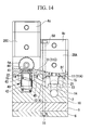
- a columnar space 13 is formed that accommodates the valve body 21 of the air pressure operating valve 20A, as shown, for example, in FIG. 14 , under the first installation area 11A.
- a vertical flow path portion 14 is formed so as to communicate with the tunnel shaped chemical fluid flow path 2 that passes in a horizontal direction through the inside of the accommodation portion of the base member 10.
- the air pressure operating valve 20A is inserted and installed by being introduced from above onto the first installation surface 11A of the base member 10 that has been formed in this manner, and for example, as shown by the imaginary line in FIG. 14 , by tightening the feedthrough bolts 50 and the nut 51a, the linking portion sealing structure is firmly held by fitting the ring-shaped concave portion 15 and the diaphragm Df together.
- the feedthrough bolt 50 and the nut 51 used here have a partitioned bolt structure for reasons to be explained below.
- the third installation surface 11C is an installation surface having a shallow depth that is formed so as to substantially align with the upper surface of the base member 10. That is, the third installation surface 11C is positioned higher than the first installation surface 11A described above.
- a columnar space for a valve body accommodating portion 42 is formed under the flow path space 16 for accommodating and installing the valve body 41 of the check valve 40.
- reference numeral 15 indicates a ring-shaped concave portion, and when the fluid apparatus is installed, a ring-shaped convex portion that is provided at the bottom portion on the fluid apparatus side is pressed as necessary therein to form a sealing structure for the linking portion.
- the air pressure operating valve 20C is inserted and installed by being introduced from above, and this is fastened by a bolt 17 (refer to FIG. 2 ) of the partitioned bolt structure described below.
- the linking portion in this case is sealed by fitting the ring-shaped convex portion 22 and the ring-shaped concave portion 15.
- the illustrated check valve 40 is structured such that the fluid flowing in from the fluid inlet 44, which is provided on the upper portion thereof, flows out at the slanted flow path 12 downward from the fluid outlet 45, which opens in the side surface of the valve body accommodating portion 42. That is, in the fluid apparatus unit 1, in which the fluid apparatus components are gathered together and integrated onto the base member 10 described above, the valve body accommodation portion 42 of a check valve 40 is formed in the base member 10, and the fluid inlet 44 and the fluid outlet 45, which communicate with this valve body accommodating portion 42, are provided so as to intersect at a desired angle, for example, so that a fluid flows in from above and flows out in a horizontal direction.
- the columnar space 13 of the first installation space 11A and the flow path space 16 of the third installation surface 11C, described above, are linked by the slanted flow path 12, which forms a portion of the pure water flow path 4.
- This slanted flow path 12 is formed by inserting tools such as a drill into the flow path space 16 from the third installation surface 11C, which is at a shallow level, and the larger the level difference between the slanted flow path space 16 and the columnar space 13, the machining of a slanted flow path 12 having a larger inclination becomes possible. That is, by making the level differences between the adjacent installation surfaces 11 large, an slanted flow path 12 having a large inclination angle can be easily formed even if a hole for machining is not provided.
- the gap between the installation surfaces 11 that can be linked by these slanted flow paths 12 can be narrowed.
- the installation angle of the slanted flow paths 12 becomes larger as the level difference becomes larger, it is possible to narrow the installation spacing.
- the installation spacing between the fluid apparatuses can be narrowed by linking the adjacent fluid apparatuses by a horizontal path such as the chemical fluid flow path 2, the machining of such a horizontal path must be carried out by using tools such as drills from the side surface of the base member 10.
- a hole for machining can be used when linked with the outside of the base member 10, but when linking the flow apparatuses within the base member 10, a hole for machining that has been formed in the side surface of the base member 10 must be closed and sealed.
- an slanted flow path 12 which is part of the chemical fluid return flow path 3 is formed from the high-level second installation side 11B, which is formed so as to substantially align with the upper surface of the base member 11B, toward the lower level fourth installation surface 11D side, which is formed so as to be bored into the upper surface of the base member 10.
- reference numeral 16 is a flow path space that is formed below the fourth installation surface 11D.
- an air pressure operating valve 20B is installed by being inserted from above onto the second installation surface 11B, and a pressure sensor 30 is installed by being inserted from above onto the fourth installation surface 11D.
- the linking portion between the air pressure operating valve 20B and the second installation surface 11B is sealed by the fitting the ring-shaped convex portion 22 and the ring-shaped concave portion 15 together, and the linking portion between the pressure sensor 30 and the fourth installation surface 11D is sealed by pressing the pressure sensor 30 onto the fourth installation surface 11D while interposing an O-ring 31 therebetween.
- a casing member 23 for the fluid apparatus components is partitioned into plural elements (for example, reference numerals 23a to 23c in the figure) in a base member 10 mating direction, and a nut portion 18a forming a female threading portion that passes through in the mating direction is fit and attached in the base side member 23c of the casing member 23 that is disposed at a position in close connection with the base member 10.
- the bolts 17 and 17 of different fastening members are threaded and tightened from both sides in the nut portion 18a with the base member 10 interposed therebetween.
- Plural nut portions 18a that are used here are provided on a female threading portion assembly 19 that is integrated by joining members 18b.
- the female threading portion assembly 19 is provided with plural nut portions 18a that are arranged at an even pitch in the peripheral direction of a cylindrical ring-shaped linking member 18b.
- the nut portions 18a are provided at four locations at a 90° pitch in the peripheral direction of the linking member 18b.
- the material for such a female threading portion assembly 19 can be suitably selected, depending on fluid characteristics and durability and the like according to use, not only from among, for example, metals such as stainless steels (SUS), but also from among resins such as polyetheretherketone, (PEEK) or polyphenylene sulfide (PPS) or the like.
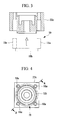
- FIG. 3 shows the cross-sectional profile of an individual component, in which the female threading portion assembly body 19 has been removed, along the cross-sectional surface A-A of the base member 23c, which is a diagonal direction, shown in FIG. 4 .
- the tightening of the bolts 17 is uniformly aligned by distributing the female threading portions 18, for example, at the four corners of the casing member 23, which has, for example, a rectangular cross-section, by using the female threading portion assembly 19 that is provided with female threading portions 18 disposed at an equal pitch in the peripheral direction.
- a substantially uniform compressing force acts from the linking member 18b over the entire mating surface, not just in the area of the location at which the bolts 17 are threaded into the female threading portion 18.
- the tightening force due to the bolts 17 acts on the mating surfaces via the ring-shaped linking member 18b, and thus, even if there is a small difference in fastening force among the four bolts 17, it is possible to obtain a uniform compressing force.
- the female threading portion assembly 19 having a structure in which the four female threading portions 18 are integrated also functions to prevent rotation when the bolts 17 are fastened.
- this facilitates the fastening operation for the bolts 17 as well.
- the other bolts 17 do not need to be restrained by a tool because they do not rotate along with the tightening of the other bolts 17, and the operability during assembly is significantly increased.
- the structure does not use 0-rings on the mating surfaces between components.
- a fluid such as a chemical fluid that, in particular, includes slurries
- the tightening torque of the bolts 17 that have been arranged and distributed requires strict control. Therefore, carrying out uniform fastening entails increasing the number of production steps.
- the linking ring 18b can uniformly compress the entire periphery of the seal surface even if the female threading portion assembly 19 cannot strictly adjust the respective tightening forces of each of the bolts 17. Therefore, because the tightening torque control of the bolts 17 and the adjusting of the force that attaches the casing member 23 to the base member 10 are facilitated, plural seal portions can be evenly tightened to obtain advantageous sealing characteristics.
- a simple structure may be used for such a partitioned bolt structure in which one feedthrough bolt 50, shown in FIG. 14 , is used and the air pressure operating valve 20B is attached to the base member 10.
- the actuator of the air pressure operating valve 20B is an air-pressure-type on-off valve, there are many sealed portions when the air pressure operating valve 20B is viewed as a unit, and therefore, when all of the sealed portions are assembled by using one feedthrough bolt 50, this causes both the assembly process and the inspection process to become complicated, which is not preferable.
- the air pressure operating valve 20B is also formed by the seal portion 63, which ensures the seal for a fluid that flows through the inside of the air pressure operating valve 20B, and a seal portion 64, which ensures the seal when the valve is opened and closed.
- the sealing function of these seals is located in the base member 10, and thus, the inspection thereof is very difficult and entails a complicated process.
- the entire apparatus must be disassembled in order to respond to any leakage that may occur, and the assembly process becomes complicated, which is not preferable.
- the reference numeral 61 in the figure is a Y-shaped packing for causing the vertical movement of a piston.
- the plural fluid apparatuses which have plural sealed parts, are arranged on the base member 10 to form a unit, similar to the air pressure operating valve 20B. Therefore, in a completed product, following the completion of the integration of the fluid apparatuses, there are many sealed portions whose sealing performance must be confirmed, and the leakage testing operation for each of the seal portions becomes an extremely complicated process. In the case that there should unfortunately be a leakage, not only must the entire apparatus be completely disassembled and then reassembled, but also specifying the locations of leaks is extremely difficult. Therefore, both the ameliorating of the risks of reassembly and the simplification of testing during the assembly process are similarly required.
- the air pressure operating valve 20B can be controlled as a unit by using the partitioned bolt structure with the nut portions 18a and the bolts 17 without being assembled by using the feedthrough bolt 17 shown in FIG. 14 . That is, by using the nut portions 18a and the bolts 17, it is possible to create a manufacturing process in which the air pressure operating valve 20B is treated as a unit, and furthermore, the air pressure operating valve 20B can be arranged on the base member 10 after confirming the respective sealing properties as a unit.
- the air pressure operating valve 20B is arranged on the first installation surface 11A of the base member 10, and a bolt 17 is inserted from the bottom of the base and threaded into the nut portion 18a.
- the integrated circuit of the fluid apparatus can be completed.
- the fluid apparatus unit 1 described above when considering the fluid apparatus unit 1 described above in terms of delivery, for a fluid apparatus such as the air pressure operating valve 20B, if similar components having, for example, differing specifications and functions and the like are manufactured and stored in suitable amounts, after suitably selected items are incorporated into the base 10 in accordance with the requests of the customer, the product can be shipped after performing leakage inspection only on the fitting portion between the ring-shaped convex portion 22 and the ring-shaped concave portion 15.
- the various similar components for the fluid apparatus described above include, for example, those in which the on-off mode, such as normally open and normally closed, differs and those in which the presence or absence of a flow rate adjusting function differs. These components are not limited to the illustrated apparatus components, but include those in which, as a single fluid apparatus, plural sealed portions are present.
- advantageous sealing performance in which the inter-surface sealing properties between the members 10 and 23 are maintained substantially uniformly over the entire periphery, can be easily obtained by a comparatively simple operation.
- the female threading portion assembly 19 of the present invention when performing an operation in which different bolts 17 are threaded and tightened from both sides of the nut portion 18a, because the female threading portion assembly 19 does not rotate along with the bolts 17, the effect is also obtained that the fastening operation of the bolts 17 is simplified.
- a base member 10 was provided with four installation surfaces 11.
- the number and disposition and the like of the installation surfaces 11 are not in particular limited thereby, and these can be suitably modified depending on the number of the fluid apparatuses to be formed into a unit. If a partitioned bolt structure, which uses the female threading portion assembly 19 in the linking structure between the installation surfaces 11 and the fluid apparatuses, is utilized, by storing similar components for the fluid apparatuses, the same base member 10 may be used, and installation of various combinations of fluid apparatus components also becomes possible. By storing the fluid apparatuses, a quick delivery response becomes possible in comparison to the case in which the entire assembly is started from scratch.
Landscapes
- Engineering & Computer Science (AREA)
- General Engineering & Computer Science (AREA)
- Mechanical Engineering (AREA)
- Valve Housings (AREA)
- Gasket Seals (AREA)
Applications Claiming Priority (2)
| Application Number | Priority Date | Filing Date | Title |
|---|---|---|---|
| JP2007139287A JP5079393B2 (ja) | 2007-05-25 | 2007-05-25 | 流体機器ユニット構造 |
| PCT/JP2008/059216 WO2008146657A1 (fr) | 2007-05-25 | 2008-05-20 | Structure d'unité d'appareils à fluide |
Publications (3)
| Publication Number | Publication Date |
|---|---|
| EP2151614A1 true EP2151614A1 (fr) | 2010-02-10 |
| EP2151614A4 EP2151614A4 (fr) | 2017-05-31 |
| EP2151614B1 EP2151614B1 (fr) | 2018-07-18 |
Family
ID=40074919
Family Applications (1)
| Application Number | Title | Priority Date | Filing Date |
|---|---|---|---|
| EP08764376.3A Active EP2151614B1 (fr) | 2007-05-25 | 2008-05-20 | Structure d'unité d'appareils à fluide |
Country Status (5)
| Country | Link |
|---|---|
| US (1) | US8522825B2 (fr) |
| EP (1) | EP2151614B1 (fr) |
| JP (1) | JP5079393B2 (fr) |
| KR (1) | KR20100022954A (fr) |
| WO (1) | WO2008146657A1 (fr) |
Families Citing this family (5)
| Publication number | Priority date | Publication date | Assignee | Title |
|---|---|---|---|---|
| JP5560276B2 (ja) * | 2009-08-31 | 2014-07-23 | 株式会社フジキン | 流体制御器 |
| JP5986450B2 (ja) | 2012-08-06 | 2016-09-06 | サーパス工業株式会社 | 空気圧操作弁及びその組立方法 |
| JP6751552B2 (ja) * | 2015-06-04 | 2020-09-09 | サーパス工業株式会社 | 流体機器 |
| US11125350B2 (en) * | 2019-03-12 | 2021-09-21 | Dresser, Llc | Valve control assembly |
| EP4335671A1 (fr) * | 2022-09-06 | 2024-03-13 | Valeo Systemes Thermiques | Module de gestion de fluide pour un véhicule |
Family Cites Families (9)
| Publication number | Priority date | Publication date | Assignee | Title |
|---|---|---|---|---|
| US2223326A (en) * | 1939-02-07 | 1940-11-26 | Linton Bausman A | Grinding wheel |
| US2457066A (en) * | 1943-08-25 | 1948-12-21 | Glenn L Martin Co | Access door for liquid containers |
| US4023257A (en) * | 1976-01-21 | 1977-05-17 | Nl Industries, Inc. | Method of making a hollow article having a reinforced aperture |
| US6394138B1 (en) * | 1996-10-30 | 2002-05-28 | Unit Instruments, Inc. | Manifold system of removable components for distribution of fluids |
| DE19716187A1 (de) * | 1997-04-18 | 1998-10-29 | Itt Mfg Enterprises Inc | Motorgetriebenes Aggregat |
| CA2332550C (fr) | 1998-05-18 | 2008-01-08 | The Swagelok Company | Assemblages distributeurs montes sur surface modulaire |
| JP3930271B2 (ja) * | 2001-02-02 | 2007-06-13 | 三菱重工業株式会社 | ロジックプレート |
| JP2005307994A (ja) * | 2004-04-16 | 2005-11-04 | Ckd Corp | 流体制御弁取付構造 |
| JP2005351309A (ja) | 2004-06-08 | 2005-12-22 | Surpass Kogyo Kk | バルブのボディおよびこれを備えたバルブ |
-
2007
- 2007-05-25 JP JP2007139287A patent/JP5079393B2/ja active Active
-
2008
- 2008-05-20 EP EP08764376.3A patent/EP2151614B1/fr active Active
- 2008-05-20 KR KR20097024056A patent/KR20100022954A/ko not_active Ceased
- 2008-05-20 US US12/600,682 patent/US8522825B2/en active Active
- 2008-05-20 WO PCT/JP2008/059216 patent/WO2008146657A1/fr not_active Ceased
Non-Patent Citations (1)
| Title |
|---|
| See references of WO2008146657A1 * |
Also Published As
| Publication number | Publication date |
|---|---|
| US20100180963A1 (en) | 2010-07-22 |
| US8522825B2 (en) | 2013-09-03 |
| JP5079393B2 (ja) | 2012-11-21 |
| KR20100022954A (ko) | 2010-03-03 |
| EP2151614A4 (fr) | 2017-05-31 |
| EP2151614B1 (fr) | 2018-07-18 |
| JP2008291942A (ja) | 2008-12-04 |
| WO2008146657A1 (fr) | 2008-12-04 |
Similar Documents
| Publication | Publication Date | Title |
|---|---|---|
| KR101321793B1 (ko) | 유체 기기 유닛 구조 | |
| US8408245B2 (en) | Valve actuator with vent | |
| US7370674B2 (en) | Modular fluid distribution system | |
| RU2526900C2 (ru) | Встраиваемый регулятор давления | |
| EP2151614B1 (fr) | Structure d'unité d'appareils à fluide | |
| EP0877170A1 (fr) | Coupleurs pour régulateurs de débit | |
| US6752377B1 (en) | Pressure relief valve with selectable orifice size | |
| KR20090080474A (ko) | 정류량 밸브 | |
| RU2496043C2 (ru) | Диафрагма с кольцевым уплотнением | |
| CN111936775A (zh) | 隔膜阀 | |
| KR20140011156A (ko) | 조립식 고압유량제어밸브 | |
| JP6929199B2 (ja) | 弁装置の漏れ検査方法及び検査装置 | |
| KR102116863B1 (ko) | 공기압 조작 밸브 및 그 조립 방법 | |
| US8602045B2 (en) | Clean-in-place valve assembly and method of operation | |
| CN105526496B (zh) | 工业分析样品容器及具有这种容器的采样设备 | |
| CN105526497B (zh) | 工业分析样品容器及具有这种容器的采样设备 | |
| EP2450607B1 (fr) | Structure d'unité de dispositif fluidique | |
| CN204240054U (zh) | 工业分析样品容器及具有这种容器的采样设备 | |
| US20230003308A1 (en) | Valve assembly and cage for a valve assembly | |
| MXPA06007991A (en) | Integrated post-guided seat ring assembly | |
| RU2472603C1 (ru) | Газостат |
Legal Events
| Date | Code | Title | Description |
|---|---|---|---|
| PUAI | Public reference made under article 153(3) epc to a published international application that has entered the european phase |
Free format text: ORIGINAL CODE: 0009012 |
|
| 17P | Request for examination filed |
Effective date: 20091119 |
|
| AK | Designated contracting states |
Kind code of ref document: A1 Designated state(s): AT BE BG CH CY CZ DE DK EE ES FI FR GB GR HR HU IE IS IT LI LT LU LV MC MT NL NO PL PT RO SE SI SK TR |
|
| AX | Request for extension of the european patent |
Extension state: AL BA MK RS |
|
| DAX | Request for extension of the european patent (deleted) | ||
| RA4 | Supplementary search report drawn up and despatched (corrected) |
Effective date: 20170502 |
|
| RIC1 | Information provided on ipc code assigned before grant |
Ipc: F16K 27/00 20060101AFI20170424BHEP Ipc: F16K 27/02 20060101ALI20170424BHEP |
|
| GRAP | Despatch of communication of intention to grant a patent |
Free format text: ORIGINAL CODE: EPIDOSNIGR1 |
|
| STAA | Information on the status of an ep patent application or granted ep patent |
Free format text: STATUS: GRANT OF PATENT IS INTENDED |
|
| INTG | Intention to grant announced |
Effective date: 20180305 |
|
| GRAS | Grant fee paid |
Free format text: ORIGINAL CODE: EPIDOSNIGR3 |
|
| GRAA | (expected) grant |
Free format text: ORIGINAL CODE: 0009210 |
|
| STAA | Information on the status of an ep patent application or granted ep patent |
Free format text: STATUS: THE PATENT HAS BEEN GRANTED |
|
| AK | Designated contracting states |
Kind code of ref document: B1 Designated state(s): AT BE BG CH CY CZ DE DK EE ES FI FR GB GR HR HU IE IS IT LI LT LU LV MC MT NL NO PL PT RO SE SI SK TR |
|
| REG | Reference to a national code |
Ref country code: GB Ref legal event code: FG4D |
|
| REG | Reference to a national code |
Ref country code: CH Ref legal event code: EP |
|
| REG | Reference to a national code |
Ref country code: IE Ref legal event code: FG4D |
|
| REG | Reference to a national code |
Ref country code: AT Ref legal event code: REF Ref document number: 1019729 Country of ref document: AT Kind code of ref document: T Effective date: 20180815 |
|
| REG | Reference to a national code |
Ref country code: DE Ref legal event code: R096 Ref document number: 602008056063 Country of ref document: DE |
|
| REG | Reference to a national code |
Ref country code: NL Ref legal event code: MP Effective date: 20180718 |
|
| REG | Reference to a national code |
Ref country code: LT Ref legal event code: MG4D |
|
| REG | Reference to a national code |
Ref country code: AT Ref legal event code: MK05 Ref document number: 1019729 Country of ref document: AT Kind code of ref document: T Effective date: 20180718 |
|
| PG25 | Lapsed in a contracting state [announced via postgrant information from national office to epo] |
Ref country code: NL Free format text: LAPSE BECAUSE OF FAILURE TO SUBMIT A TRANSLATION OF THE DESCRIPTION OR TO PAY THE FEE WITHIN THE PRESCRIBED TIME-LIMIT Effective date: 20180718 |
|
| PG25 | Lapsed in a contracting state [announced via postgrant information from national office to epo] |
Ref country code: IS Free format text: LAPSE BECAUSE OF FAILURE TO SUBMIT A TRANSLATION OF THE DESCRIPTION OR TO PAY THE FEE WITHIN THE PRESCRIBED TIME-LIMIT Effective date: 20181118 Ref country code: PL Free format text: LAPSE BECAUSE OF FAILURE TO SUBMIT A TRANSLATION OF THE DESCRIPTION OR TO PAY THE FEE WITHIN THE PRESCRIBED TIME-LIMIT Effective date: 20180718 Ref country code: LT Free format text: LAPSE BECAUSE OF FAILURE TO SUBMIT A TRANSLATION OF THE DESCRIPTION OR TO PAY THE FEE WITHIN THE PRESCRIBED TIME-LIMIT Effective date: 20180718 Ref country code: AT Free format text: LAPSE BECAUSE OF FAILURE TO SUBMIT A TRANSLATION OF THE DESCRIPTION OR TO PAY THE FEE WITHIN THE PRESCRIBED TIME-LIMIT Effective date: 20180718 Ref country code: GR Free format text: LAPSE BECAUSE OF FAILURE TO SUBMIT A TRANSLATION OF THE DESCRIPTION OR TO PAY THE FEE WITHIN THE PRESCRIBED TIME-LIMIT Effective date: 20181019 Ref country code: FI Free format text: LAPSE BECAUSE OF FAILURE TO SUBMIT A TRANSLATION OF THE DESCRIPTION OR TO PAY THE FEE WITHIN THE PRESCRIBED TIME-LIMIT Effective date: 20180718 Ref country code: SE Free format text: LAPSE BECAUSE OF FAILURE TO SUBMIT A TRANSLATION OF THE DESCRIPTION OR TO PAY THE FEE WITHIN THE PRESCRIBED TIME-LIMIT Effective date: 20180718 Ref country code: NO Free format text: LAPSE BECAUSE OF FAILURE TO SUBMIT A TRANSLATION OF THE DESCRIPTION OR TO PAY THE FEE WITHIN THE PRESCRIBED TIME-LIMIT Effective date: 20181018 Ref country code: BG Free format text: LAPSE BECAUSE OF FAILURE TO SUBMIT A TRANSLATION OF THE DESCRIPTION OR TO PAY THE FEE WITHIN THE PRESCRIBED TIME-LIMIT Effective date: 20181018 |
|
| PG25 | Lapsed in a contracting state [announced via postgrant information from national office to epo] |
Ref country code: HR Free format text: LAPSE BECAUSE OF FAILURE TO SUBMIT A TRANSLATION OF THE DESCRIPTION OR TO PAY THE FEE WITHIN THE PRESCRIBED TIME-LIMIT Effective date: 20180718 Ref country code: LV Free format text: LAPSE BECAUSE OF FAILURE TO SUBMIT A TRANSLATION OF THE DESCRIPTION OR TO PAY THE FEE WITHIN THE PRESCRIBED TIME-LIMIT Effective date: 20180718 Ref country code: ES Free format text: LAPSE BECAUSE OF FAILURE TO SUBMIT A TRANSLATION OF THE DESCRIPTION OR TO PAY THE FEE WITHIN THE PRESCRIBED TIME-LIMIT Effective date: 20180718 |
|
| REG | Reference to a national code |
Ref country code: DE Ref legal event code: R097 Ref document number: 602008056063 Country of ref document: DE |
|
| PG25 | Lapsed in a contracting state [announced via postgrant information from national office to epo] |
Ref country code: IT Free format text: LAPSE BECAUSE OF FAILURE TO SUBMIT A TRANSLATION OF THE DESCRIPTION OR TO PAY THE FEE WITHIN THE PRESCRIBED TIME-LIMIT Effective date: 20180718 Ref country code: CZ Free format text: LAPSE BECAUSE OF FAILURE TO SUBMIT A TRANSLATION OF THE DESCRIPTION OR TO PAY THE FEE WITHIN THE PRESCRIBED TIME-LIMIT Effective date: 20180718 Ref country code: RO Free format text: LAPSE BECAUSE OF FAILURE TO SUBMIT A TRANSLATION OF THE DESCRIPTION OR TO PAY THE FEE WITHIN THE PRESCRIBED TIME-LIMIT Effective date: 20180718 Ref country code: EE Free format text: LAPSE BECAUSE OF FAILURE TO SUBMIT A TRANSLATION OF THE DESCRIPTION OR TO PAY THE FEE WITHIN THE PRESCRIBED TIME-LIMIT Effective date: 20180718 |
|
| PLBE | No opposition filed within time limit |
Free format text: ORIGINAL CODE: 0009261 |
|
| STAA | Information on the status of an ep patent application or granted ep patent |
Free format text: STATUS: NO OPPOSITION FILED WITHIN TIME LIMIT |
|
| PG25 | Lapsed in a contracting state [announced via postgrant information from national office to epo] |
Ref country code: SK Free format text: LAPSE BECAUSE OF FAILURE TO SUBMIT A TRANSLATION OF THE DESCRIPTION OR TO PAY THE FEE WITHIN THE PRESCRIBED TIME-LIMIT Effective date: 20180718 Ref country code: DK Free format text: LAPSE BECAUSE OF FAILURE TO SUBMIT A TRANSLATION OF THE DESCRIPTION OR TO PAY THE FEE WITHIN THE PRESCRIBED TIME-LIMIT Effective date: 20180718 |
|
| 26N | No opposition filed |
Effective date: 20190423 |
|
| PG25 | Lapsed in a contracting state [announced via postgrant information from national office to epo] |
Ref country code: SI Free format text: LAPSE BECAUSE OF FAILURE TO SUBMIT A TRANSLATION OF THE DESCRIPTION OR TO PAY THE FEE WITHIN THE PRESCRIBED TIME-LIMIT Effective date: 20180718 |
|
| REG | Reference to a national code |
Ref country code: CH Ref legal event code: PL |
|
| GBPC | Gb: european patent ceased through non-payment of renewal fee |
Effective date: 20190520 |
|
| PG25 | Lapsed in a contracting state [announced via postgrant information from national office to epo] |
Ref country code: CH Free format text: LAPSE BECAUSE OF NON-PAYMENT OF DUE FEES Effective date: 20190531 Ref country code: LI Free format text: LAPSE BECAUSE OF NON-PAYMENT OF DUE FEES Effective date: 20190531 Ref country code: MC Free format text: LAPSE BECAUSE OF FAILURE TO SUBMIT A TRANSLATION OF THE DESCRIPTION OR TO PAY THE FEE WITHIN THE PRESCRIBED TIME-LIMIT Effective date: 20180718 |
|
| REG | Reference to a national code |
Ref country code: BE Ref legal event code: MM Effective date: 20190531 |
|
| PG25 | Lapsed in a contracting state [announced via postgrant information from national office to epo] |
Ref country code: LU Free format text: LAPSE BECAUSE OF NON-PAYMENT OF DUE FEES Effective date: 20190520 |
|
| PG25 | Lapsed in a contracting state [announced via postgrant information from national office to epo] |
Ref country code: TR Free format text: LAPSE BECAUSE OF FAILURE TO SUBMIT A TRANSLATION OF THE DESCRIPTION OR TO PAY THE FEE WITHIN THE PRESCRIBED TIME-LIMIT Effective date: 20180718 |
|
| PG25 | Lapsed in a contracting state [announced via postgrant information from national office to epo] |
Ref country code: GB Free format text: LAPSE BECAUSE OF NON-PAYMENT OF DUE FEES Effective date: 20190520 Ref country code: IE Free format text: LAPSE BECAUSE OF NON-PAYMENT OF DUE FEES Effective date: 20190520 |
|
| PG25 | Lapsed in a contracting state [announced via postgrant information from national office to epo] |
Ref country code: BE Free format text: LAPSE BECAUSE OF NON-PAYMENT OF DUE FEES Effective date: 20190531 |
|
| PG25 | Lapsed in a contracting state [announced via postgrant information from national office to epo] |
Ref country code: PT Free format text: LAPSE BECAUSE OF FAILURE TO SUBMIT A TRANSLATION OF THE DESCRIPTION OR TO PAY THE FEE WITHIN THE PRESCRIBED TIME-LIMIT Effective date: 20181118 Ref country code: FR Free format text: LAPSE BECAUSE OF NON-PAYMENT OF DUE FEES Effective date: 20190531 |
|
| PG25 | Lapsed in a contracting state [announced via postgrant information from national office to epo] |
Ref country code: CY Free format text: LAPSE BECAUSE OF FAILURE TO SUBMIT A TRANSLATION OF THE DESCRIPTION OR TO PAY THE FEE WITHIN THE PRESCRIBED TIME-LIMIT Effective date: 20180718 |
|
| PG25 | Lapsed in a contracting state [announced via postgrant information from national office to epo] |
Ref country code: HU Free format text: LAPSE BECAUSE OF FAILURE TO SUBMIT A TRANSLATION OF THE DESCRIPTION OR TO PAY THE FEE WITHIN THE PRESCRIBED TIME-LIMIT; INVALID AB INITIO Effective date: 20080520 Ref country code: MT Free format text: LAPSE BECAUSE OF FAILURE TO SUBMIT A TRANSLATION OF THE DESCRIPTION OR TO PAY THE FEE WITHIN THE PRESCRIBED TIME-LIMIT Effective date: 20180718 |
|
| PGFP | Annual fee paid to national office [announced via postgrant information from national office to epo] |
Ref country code: DE Payment date: 20250521 Year of fee payment: 18 |