EP2151678A2 - Verfahren zur Berücksichtigung des dynamischen Verhaltens eines bewegbaren Elements einer Maschine zur Durchführung einer Radermüdungsprüfung - Google Patents
Verfahren zur Berücksichtigung des dynamischen Verhaltens eines bewegbaren Elements einer Maschine zur Durchführung einer Radermüdungsprüfung Download PDFInfo
- Publication number
- EP2151678A2 EP2151678A2 EP09152705A EP09152705A EP2151678A2 EP 2151678 A2 EP2151678 A2 EP 2151678A2 EP 09152705 A EP09152705 A EP 09152705A EP 09152705 A EP09152705 A EP 09152705A EP 2151678 A2 EP2151678 A2 EP 2151678A2
- Authority
- EP
- European Patent Office
- Prior art keywords
- wheel
- bending moment
- movable member
- machine
- force
- Prior art date
- Legal status (The legal status is an assumption and is not a legal conclusion. Google has not performed a legal analysis and makes no representation as to the accuracy of the status listed.)
- Granted
Links
- 238000000034 method Methods 0.000 title claims abstract description 28
- 238000009661 fatigue test Methods 0.000 title claims abstract description 12
- 238000005452 bending Methods 0.000 claims abstract description 80
- 238000012360 testing method Methods 0.000 claims description 10
- 230000003068 static effect Effects 0.000 claims description 6
- 230000033001 locomotion Effects 0.000 description 4
- 230000008878 coupling Effects 0.000 description 3
- 238000010168 coupling process Methods 0.000 description 3
- 238000005859 coupling reaction Methods 0.000 description 3
- 230000000694 effects Effects 0.000 description 3
- 238000010586 diagram Methods 0.000 description 2
- 238000006073 displacement reaction Methods 0.000 description 2
- 238000012986 modification Methods 0.000 description 2
- 230000004048 modification Effects 0.000 description 2
- 230000005540 biological transmission Effects 0.000 description 1
- 125000004122 cyclic group Chemical group 0.000 description 1
- 238000005516 engineering process Methods 0.000 description 1
- 230000005484 gravity Effects 0.000 description 1
Images
Classifications
-
- G—PHYSICS
- G01—MEASURING; TESTING
- G01M—TESTING STATIC OR DYNAMIC BALANCE OF MACHINES OR STRUCTURES; TESTING OF STRUCTURES OR APPARATUS, NOT OTHERWISE PROVIDED FOR
- G01M17/00—Testing of vehicles
- G01M17/007—Wheeled or endless-tracked vehicles
- G01M17/013—Wheels
-
- G—PHYSICS
- G01—MEASURING; TESTING
- G01N—INVESTIGATING OR ANALYSING MATERIALS BY DETERMINING THEIR CHEMICAL OR PHYSICAL PROPERTIES
- G01N3/00—Investigating strength properties of solid materials by application of mechanical stress
- G01N3/32—Investigating strength properties of solid materials by application of mechanical stress by applying repeated or pulsating forces
-
- G—PHYSICS
- G01—MEASURING; TESTING
- G01N—INVESTIGATING OR ANALYSING MATERIALS BY DETERMINING THEIR CHEMICAL OR PHYSICAL PROPERTIES
- G01N33/00—Investigating or analysing materials by specific methods not covered by groups G01N1/00 - G01N31/00
- G01N33/0078—Testing material properties on manufactured objects
- G01N33/0083—Vehicle parts
- G01N33/0085—Wheels
-
- G—PHYSICS
- G01—MEASURING; TESTING
- G01N—INVESTIGATING OR ANALYSING MATERIALS BY DETERMINING THEIR CHEMICAL OR PHYSICAL PROPERTIES
- G01N2203/00—Investigating strength properties of solid materials by application of mechanical stress
- G01N2203/0014—Type of force applied
- G01N2203/0023—Bending
Definitions
- This invention relates to a method of considering the dynamic behaviour of a movable member of a machine for performing a wheel fatigue test, and more particularly to a method of determining a bending moment applied to the wheel as the member moves.
- Wheels typically are constituted by two main parts namely a circular rim to which in use, a tyre is mounted, and a disc by means of which the wheel is securable to a hub of a vehicle.
- a fatigue test which involves clamping the rim to a fixed structure and attaching the disc to a member which moves to apply a bending moment to the wheel. Accurate determination of the bending moment applied is required for the testing method.
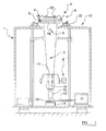
- the machine 10 includes a member which in this example is a generally frusto-conical shaft 3 which carries at an upper end thereof, a simulated vesicle hub 5. At its lower end, the hub-carrying shaft 3 is coupled to a drive shaft 11 which is rotated in use, and relative to the hub-carrying shaft 3, by operation of an electric motor 7, the rotational speed of which is controllable.
- the motor 7 is connected to the drive shaft 11 at or towards a lower end of the drive shaft 11 remote from the simulated hub 5, by a transmission such as a belt or chain or gear train 12.
- the lowest end 13 of the drive shaft 11 is received in a bearing structure 14.
- a lower region 15 of the drive shaft 11 is generally cylindrical.
- a region of the drive shaft 11 above the lower region 15, indicated at 16, has secured to the drive shaft 11, an eccentrically carried mass 8 which rotates with the drive shaft 11 to impart a cyclically varying force on the hub mounting shaft 3 as is described below.
- An upper end 18 of the frusto-conical hub-carrying shaft 3, where the simulated hub is carried, is the largest diameter end, most closely to simulate the hub 5 mounting to a vehicle.
- a wheel 2 is secured to the simulated hub 5 by the same kind of fixings by which the wheel 2 in use, would be secured to a vehicle hub.
- the fixings are a plurality of bolts 20 which pass through openings in the wheel disc 4, and are screwed into the simulated hub 5.
- the disc 4 is fixed to the simulated hub 5.
- the wheel rim 6 is immovably fixed relative to the fixed structure 1 by one or a plurality of clamps provided around the circumference of the rim 6, or preferably as shown, a continuous circular damp 22 is provided which clamps the rim 6 to the fixed structure 10 around its entire periphery.
- the motor 7 is operated to rotate the drive shaft 11.
- the eccentrically mounted mass 8 is rotated with the shaft 3 and originates a centrifugal force, which because of the distance between the application direction of the force i.e. the distance from where the mass 8 is secured to the shaft 3, and the hub 5 above, creates a bending moment on the disc 4 transmitted along the hub-carrying shaft 3, via the hub 5, and to the wheel.
- the rotating eccentric mass 8 will cause the lower end of the hub-carrying shaft 3 to undergo a circular, precessional, motion, whilst the upper end of the hub-carrying shaft 3 will be restrained from movement by the rim being fixed to the fixed structure 1 so that a cyclic bending moment is applied to the wheel 2.
- the machine 10 includes a strain gauge 9 which is attached to the hub-carrying shaft 3 towards the upper end of 18 of the shaft 3, the strain gauge 9 being coupled to a bridge or other suitable circuit, which provides an output to an analysing apparatus which conditions and uses the signal, to provide a determination of the bending moment applied to the wheel 2 during the test.
- Such a machine 10 is intended to simulate conditions the wheel 2 will experience in use when mounted on a hub of an actual vehicle, during cornering, when the wheel 2 will be subject to the greatest bending moments.
- Such factors include for examples only, any eccentricity of the hub-carrying shaft, the stiffness of the wheel being tested, the weight of the eccentric mass and, although this is not a major contributor, the contribution to bending moment of any part of the machine beyond the position of the strain gauge on the hub-carrying shaft, such as an uppermost part of the hub-carrying shaft itself, and the simulated hub carried by the shaft.
- a displacement of a centre of gravity of the hub-carrying shaft may occur due to the flexibility of components of the machine, and which displacement is greatly influenced by the weight of the eccentrically mounted mass and the speed of rotation of the drive shaft.
- This can cause a second centrifugal force to be generated which is proportional to the mass of the hub-carrying shaft and applied to its barycentre, in addition to the first mentioned centrifugal force generated by the rotating eccentrically mounted mass.
- the actual stiffness of the wheel under test has a not insignificant effect on the flexibility of the whole system.
- the method includes applying a first strain gauge to a surface of the movable member at the first position, and applying a second strain gauge to the surface of the movable member at the second position and using readings from the first and second strain gauges to determine an indication of the bending moment at each of the first and second positions.
- the movable member is moved to exert the cyclical force to generate the bending moment in the wheel, by generating a first force by rotating a mass which is eccentrically mounted with respect to its axis of rotation, and coupling the mass to the movable member to generate a cyclical centrifugal force to the movable member.
- the force F is the resultant of the force which is applied by the rotating mass to move the movable member, and a resultant force due to the dynamic behaviour of the machine, and that the distance x is representative of the distance from the wheel, where the actual bending moment is applied, to where the resultant force F is applied.
- the movable member is, at least when in a static condition substantially vertical, and the first and second positions are substantially aligned substantially vertically.
- the first and second positions are preferably aligned along the cone axis and located at the conical surface of the member.
- the method of the second aspect of the invention may include any of the features of the method according to the first aspect of the invention.
- the machine may include a simulated vehicle hub to which the wheel disc is secured by fastenings, the hub being carried at one end of the movable member.
- the movable member may in use, be substantially vertical, and the first and second positions may be substantially aligned vertically.
- the movable member is frusto-conical, and the first and second positions are aligned along the cone axis and located at the conical surface of the member.
- the first and second sensors may each be strain gauges and the analysing apparatus may include a processor to determine from the signals from the first and second sensors, an indication of bending moment experienced at each of the first and second positions.
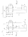
- the testing machine 10 of figure 2 is substantially similar to that of figure 1 , even though the configuration of the various machine 10 parts, and the wheel 2 under test are shown with less detail.
- the modification to the figure 1 testing machine 10 which is made in figure 2 is the provision of first and second strain gauges 9a and 9b rather than the single strain gauge 9, with each of the two strain gauges 9a and 9b being connected operatively, to an analysing apparatus A which includes a processor, which from both of the signals from the strain gauges 9a, 9b determines more accurately the bending moment applied to the wheel 2 during testing, than is achievable with the figure 1 machine 10.
- the first and second strain gauges 9a, 9b are substantially aligned.
- the two strain gauges 9a, 9b are vertically aligned axially along the hub-carrying shaft 3, located at the surface of the shaft 3.
- the strain gauges 9a, 9b are located on the conical surface of the shaft 3, but still in vertical alignment along the cone axis.
- the first strain gauge 9a is located at a first position with a distance a from where the bending moment is applied to the wheel 2, whilst the second strain gauge 9b is located at a second position b from where the bending moment is applied to the wheel 2.
- the first and second strain gauges 9a, 9b are a distance d apart.
- the eccentric weight 8 is at a distant position from the wheel 2, which is a distance h from where the bending moment is applied to the wheel 2.
- a resultant force F 2 will be exerted on the shaft 3 which is due to the dynamic behaviour of the machine 10 as a result of e.g. any eccentricity of the hub-carrying shaft 3, the stiffness of the wheel 2 being tested (which may be stiffer at different circumferential positions) the weight of the eccentric mass 8 and the contribution to bending moment of any part of the machine 10 beyond the position of the second strain gauge 9b on the hub-carrying shaft 3, such as the uppermost part 18 of the hub-carrying shaft 3 itself, and the simulated hub 5 carried by the shaft 3.
- the actual force applied to the wheel 2 is the resultant of the forces F 1 and F 2 , and is indicated at F in figure 3 .
- the actual force F can be considered as the an eccentrically mounted weight 8' acting on the shaft 3, at an unknown position a distance x from where the bending moment is applied to the wheel 2.
- the signals from each of the first and second strain gauges 9a and 9b can be processed in the analysing apparatus A to provide determinations of bending moments experienced M 1 , M 2 respectively, at the respective first and second positions.
- the present invention thus enables a more accurate determination, taking into account the dynamic behaviour of the machine 10, of the actual bending moment applied to the wheel 2 by movable member 3 of the machine 10 during fatigue testing.
- the configuration of the machine 10 described may be varied, for example by providing a movable member 3 of a configuration other than frusto-conical.
- the movable member 3 may be cylindrical
- the wheel 2 may be carried on the movable member 3 other than by a simulated hub 5 although the closer the machine 10 can be made to simulate actual wheel operating conditions, the more relevant the test results will be to the wheels' actual fatigue characteristic.
- the wheel 2 is tested in the orientation described in which the movable member is arranged substantially upright, to avoid gravitational effects, in an alternative machine, the wheel 2 may be in another orientation, for example with the movable member 3 arranged generally horizontally.
- strain gauges 9a and 9b to determine the bending moments at the first and second positions
- some other kinds of sensors may alternatively be used.
- the coupling of the drive shaft 11 to the movable member 3 may be substantially rigid, or may be a resilient coupling, provided that the drive shaft 11 can rotate relative to the movable member 3.
- the drive shaft 11 itself, or part of it such as the lower region 15 of the drive shaft 11, may be resiliently mounted, to permit the rotating eccentric weight 8 to impart the force necessary to the movable member 3 to cause the movable member 3 to move in a circular, recessional path, at the lowest end when in the orientation of the movable member 3 in the drawings, to transmit the bending moment to the wheel 2 at the uppermost end 18 of the movable member 3.
- the degree of residence of the parts of the machine 10 will be selected depending on the motion required of the movable member 3 to provide a desired bending moment in the wheel 2.
- a movable member 3 to which the wheel disc 4 is secured may otherwise be moved to exert a cynical bending moment on the wheel 2.
Landscapes
- Physics & Mathematics (AREA)
- General Physics & Mathematics (AREA)
- Life Sciences & Earth Sciences (AREA)
- Chemical & Material Sciences (AREA)
- Health & Medical Sciences (AREA)
- General Health & Medical Sciences (AREA)
- Analytical Chemistry (AREA)
- Biochemistry (AREA)
- Immunology (AREA)
- Pathology (AREA)
- Medicinal Chemistry (AREA)
- Food Science & Technology (AREA)
- Engineering & Computer Science (AREA)
- Investigating Strength Of Materials By Application Of Mechanical Stress (AREA)
Applications Claiming Priority (1)
| Application Number | Priority Date | Filing Date | Title |
|---|---|---|---|
| GB0814037.8A GB2462300B (en) | 2008-07-31 | 2008-07-31 | A method of considering the dynamic behaviour of a moveable member of a machine for performing a wheel fatigue test |
Publications (3)
| Publication Number | Publication Date |
|---|---|
| EP2151678A2 true EP2151678A2 (de) | 2010-02-10 |
| EP2151678A3 EP2151678A3 (de) | 2012-09-05 |
| EP2151678B1 EP2151678B1 (de) | 2013-10-23 |
Family
ID=39767315
Family Applications (1)
| Application Number | Title | Priority Date | Filing Date |
|---|---|---|---|
| EP09152705.1A Not-in-force EP2151678B1 (de) | 2008-07-31 | 2009-02-12 | Verfahren zur Berücksichtigung des dynamischen Verhaltens eines bewegbaren Elements einer Maschine zur Durchführung einer Radermüdungsprüfung |
Country Status (3)
| Country | Link |
|---|---|
| US (1) | US8037773B2 (de) |
| EP (1) | EP2151678B1 (de) |
| GB (1) | GB2462300B (de) |
Cited By (2)
| Publication number | Priority date | Publication date | Assignee | Title |
|---|---|---|---|---|
| CN102621015A (zh) * | 2012-03-26 | 2012-08-01 | 河海大学 | 疲劳试验机 |
| EP3168592A1 (de) * | 2015-11-12 | 2017-05-17 | Joachim Hug | Radprüfeinrichtung und verfahren zum betreiben derselben |
Families Citing this family (8)
| Publication number | Priority date | Publication date | Assignee | Title |
|---|---|---|---|---|
| RU2528120C1 (ru) * | 2013-03-12 | 2014-09-10 | Федеральное государственное бюджетное образовательное учреждение высшего профессионального образования "Национальный минерально-сырьевой университет "Горный" | Установка для испытания образцов материалов на изгиб |
| RU2536090C1 (ru) * | 2013-06-18 | 2014-12-20 | Федеральное государственное бюджетное образовательное учреждение высшего профессионального образования "Национальный минерально-сырьевой университет "Горный" | Установка для испытания образцов на изгиб |
| EP3115767B1 (de) * | 2015-07-06 | 2020-06-24 | MW Italia S.r.l. | Verfahren zur mechanischen charakterisierung eines metallischen materials zur radscheibenherstellung |
| CN106092791B (zh) * | 2016-07-05 | 2018-05-08 | 潘唯锡 | 车辆轮毂交变受力弯曲的测试设备 |
| US10345144B2 (en) * | 2017-07-11 | 2019-07-09 | Bae Systems Information And Electronics Systems Integration Inc. | Compact and athermal VNIR/SWIR spectrometer |
| CN108007802B (zh) * | 2017-12-10 | 2019-05-28 | 北京化工大学 | 一种基于快速傅里叶变换的材料动态疲劳测试系统及方法 |
| FR3088116B1 (fr) * | 2018-11-02 | 2021-01-29 | Accuride Wheels Troyes Sas | Machine et procede de test de systeme de fixation de roue de vehicule automobile |
| CN119803962B (zh) * | 2024-12-16 | 2025-10-17 | 太原科技大学 | 车辆鼓式制动轮毂疲劳寿命实验装置 |
Citations (2)
| Publication number | Priority date | Publication date | Assignee | Title |
|---|---|---|---|---|
| US3961525A (en) | 1973-12-17 | 1976-06-08 | Gebr. Hofmann Kg | Method of and device for resting the fatigue strength of rotors, especially disc wheels, especially those for motor vehicles |
| DE3321827C1 (de) | 1983-06-15 | 1984-07-12 | Mannesmann Kronprinz Ag, 5650 Solingen | Verfahren zur Regelung von Prüfungsmaschinen mit Unwuchtbelastung |
Family Cites Families (6)
| Publication number | Priority date | Publication date | Assignee | Title |
|---|---|---|---|---|
| US2953018A (en) * | 1958-10-22 | 1960-09-20 | Kronprinz Ag | Fatigue testing machine for automobile wheels |
| US4172524A (en) * | 1977-05-04 | 1979-10-30 | The Upjohn Company | Inspection system |
| DE3604186A1 (de) * | 1986-02-10 | 1987-08-13 | Fraunhofer Ges Forschung | Verfahren und einrichtung zur pruefung von schienenfahrzeugraedern unter betriebsaehnlichen belastungsbedingungen |
| US4998440A (en) * | 1989-11-29 | 1991-03-12 | Baumel Stanley J | Apparatus and method for fatigue testing a wheel |
| US5046368A (en) * | 1989-11-29 | 1991-09-10 | Baumel Stanley J | Apparatus and method for fatigue testing a wheel |
| US20060153482A1 (en) * | 2003-04-07 | 2006-07-13 | Ntn Corporation | Wheel support bearing assembly with built-in load sensor |
-
2008
- 2008-07-31 GB GB0814037.8A patent/GB2462300B/en not_active Expired - Fee Related
-
2009
- 2009-02-12 EP EP09152705.1A patent/EP2151678B1/de not_active Not-in-force
- 2009-05-29 US US12/474,839 patent/US8037773B2/en not_active Expired - Fee Related
Patent Citations (2)
| Publication number | Priority date | Publication date | Assignee | Title |
|---|---|---|---|---|
| US3961525A (en) | 1973-12-17 | 1976-06-08 | Gebr. Hofmann Kg | Method of and device for resting the fatigue strength of rotors, especially disc wheels, especially those for motor vehicles |
| DE3321827C1 (de) | 1983-06-15 | 1984-07-12 | Mannesmann Kronprinz Ag, 5650 Solingen | Verfahren zur Regelung von Prüfungsmaschinen mit Unwuchtbelastung |
Cited By (3)
| Publication number | Priority date | Publication date | Assignee | Title |
|---|---|---|---|---|
| CN102621015A (zh) * | 2012-03-26 | 2012-08-01 | 河海大学 | 疲劳试验机 |
| CN102621015B (zh) * | 2012-03-26 | 2013-06-05 | 河海大学 | 疲劳试验机 |
| EP3168592A1 (de) * | 2015-11-12 | 2017-05-17 | Joachim Hug | Radprüfeinrichtung und verfahren zum betreiben derselben |
Also Published As
| Publication number | Publication date |
|---|---|
| GB2462300B (en) | 2012-06-06 |
| GB2462300A8 (en) | 2010-03-10 |
| EP2151678A3 (de) | 2012-09-05 |
| GB0814037D0 (en) | 2008-09-10 |
| US20100024565A1 (en) | 2010-02-04 |
| EP2151678B1 (de) | 2013-10-23 |
| US8037773B2 (en) | 2011-10-18 |
| HK1140818A1 (en) | 2010-10-22 |
| GB2462300A (en) | 2010-02-03 |
Similar Documents
| Publication | Publication Date | Title |
|---|---|---|
| EP2151678B1 (de) | Verfahren zur Berücksichtigung des dynamischen Verhaltens eines bewegbaren Elements einer Maschine zur Durchführung einer Radermüdungsprüfung | |
| JP5562053B2 (ja) | 多分力計のモーメント校正装置及び校正方法 | |
| JP3338214B2 (ja) | ダイナモメーター | |
| EP2711206B1 (de) | Vorrichtung zur Wartung von Fahrzeugrädern | |
| EP2880412B1 (de) | Auswuchtvorrichtung für fahrzeugräder | |
| US6606569B1 (en) | Methods and systems for dynamic force measurement | |
| CN102706496B (zh) | 用于测量不平衡产生的力的装置 | |
| US10371593B2 (en) | Dynamic balancer | |
| EP3839468A1 (de) | Verfahren zum auswuchten eines rotors | |
| PL225215B1 (pl) | Wyważarka wałów przegubowych i sposób wyważania wałów przegubowych | |
| US20220214238A1 (en) | Devices and methods for monitoring health and performance of a mechanical system | |
| US11422066B2 (en) | Tire testing machine, method for testing a tire and computer program | |
| CN106610332A (zh) | 检测电动车车轮的平衡机及采用该平衡机检测动、静平衡中不平衡质量的方法 | |
| JPH0843234A (ja) | 自動車に組立てられたドライブシャフトの釣合わせ方法 | |
| US3961525A (en) | Method of and device for resting the fatigue strength of rotors, especially disc wheels, especially those for motor vehicles | |
| US8899111B2 (en) | Device for measuring forces generated by an unbalance | |
| JP2009222639A (ja) | タイヤ試験装置及びタイヤ試験方法 | |
| CN209495846U (zh) | 扭矩加载装置 | |
| EP3839469B1 (de) | Rotorauswuchtvorrichtung | |
| Gagliano et al. | Indoor/outdoor testing of a passenger car suspension for vibration and harshness analysis | |
| KR100869193B1 (ko) | 불균형 측정장치를 교정하기 위한 방법 및 장치 | |
| KR101829436B1 (ko) | 고속회전하는 타이어의 동 스프링계수측정 시험장치 | |
| EP3943906A1 (de) | Handbetätigte rotorauswuchtvorrichtung, verfahren zum manuellen auswuchten eines rotors und steuereinheit | |
| RU2155944C1 (ru) | Способ балансировки автомобильных колес и устройство для его осуществления | |
| RU140040U1 (ru) | Стенд для испытаний образцов резьбовых соединений на усталостную выносливость |
Legal Events
| Date | Code | Title | Description |
|---|---|---|---|
| PUAI | Public reference made under article 153(3) epc to a published international application that has entered the european phase |
Free format text: ORIGINAL CODE: 0009012 |
|
| AK | Designated contracting states |
Kind code of ref document: A2 Designated state(s): AT BE BG CH CY CZ DE DK EE ES FI FR GB GR HR HU IE IS IT LI LT LU LV MC MK MT NL NO PL PT RO SE SI SK TR |
|
| AX | Request for extension of the european patent |
Extension state: AL BA RS |
|
| RAP1 | Party data changed (applicant data changed or rights of an application transferred) |
Owner name: GKN LAND SYSTEMS LIMITED |
|
| PUAL | Search report despatched |
Free format text: ORIGINAL CODE: 0009013 |
|
| AK | Designated contracting states |
Kind code of ref document: A3 Designated state(s): AT BE BG CH CY CZ DE DK EE ES FI FR GB GR HR HU IE IS IT LI LT LU LV MC MK MT NL NO PL PT RO SE SI SK TR |
|
| AX | Request for extension of the european patent |
Extension state: AL BA RS |
|
| RIC1 | Information provided on ipc code assigned before grant |
Ipc: G01M 17/013 20060101AFI20120731BHEP Ipc: G01N 3/32 20060101ALI20120731BHEP |
|
| 17P | Request for examination filed |
Effective date: 20130226 |
|
| RIC1 | Information provided on ipc code assigned before grant |
Ipc: G01M 17/013 20060101AFI20130325BHEP Ipc: G01N 3/32 20060101ALI20130325BHEP |
|
| AKX | Designation fees paid |
Designated state(s): AT BE BG CH CY CZ DE DK EE ES FI FR GB GR HR HU IE IS IT LI LT LU LV MC MK MT NL NO PL PT RO SE SI SK TR |
|
| GRAP | Despatch of communication of intention to grant a patent |
Free format text: ORIGINAL CODE: EPIDOSNIGR1 |
|
| INTG | Intention to grant announced |
Effective date: 20130510 |
|
| GRAS | Grant fee paid |
Free format text: ORIGINAL CODE: EPIDOSNIGR3 |
|
| GRAA | (expected) grant |
Free format text: ORIGINAL CODE: 0009210 |
|
| AK | Designated contracting states |
Kind code of ref document: B1 Designated state(s): AT BE BG CH CY CZ DE DK EE ES FI FR GB GR HR HU IE IS IT LI LT LU LV MC MK MT NL NO PL PT RO SE SI SK TR |
|
| REG | Reference to a national code |
Ref country code: GB Ref legal event code: FG4D |
|
| REG | Reference to a national code |
Ref country code: CH Ref legal event code: EP |
|
| REG | Reference to a national code |
Ref country code: AT Ref legal event code: REF Ref document number: 637852 Country of ref document: AT Kind code of ref document: T Effective date: 20131115 |
|
| REG | Reference to a national code |
Ref country code: IE Ref legal event code: FG4D |
|
| REG | Reference to a national code |
Ref country code: DE Ref legal event code: R096 Ref document number: 602009019569 Country of ref document: DE Effective date: 20131219 |
|
| REG | Reference to a national code |
Ref country code: NL Ref legal event code: VDEP Effective date: 20131023 |
|
| REG | Reference to a national code |
Ref country code: AT Ref legal event code: MK05 Ref document number: 637852 Country of ref document: AT Kind code of ref document: T Effective date: 20131023 |
|
| REG | Reference to a national code |
Ref country code: LT Ref legal event code: MG4D |
|
| PG25 | Lapsed in a contracting state [announced via postgrant information from national office to epo] |
Ref country code: LT Free format text: LAPSE BECAUSE OF FAILURE TO SUBMIT A TRANSLATION OF THE DESCRIPTION OR TO PAY THE FEE WITHIN THE PRESCRIBED TIME-LIMIT Effective date: 20131023 Ref country code: FI Free format text: LAPSE BECAUSE OF FAILURE TO SUBMIT A TRANSLATION OF THE DESCRIPTION OR TO PAY THE FEE WITHIN THE PRESCRIBED TIME-LIMIT Effective date: 20131023 Ref country code: NO Free format text: LAPSE BECAUSE OF FAILURE TO SUBMIT A TRANSLATION OF THE DESCRIPTION OR TO PAY THE FEE WITHIN THE PRESCRIBED TIME-LIMIT Effective date: 20140123 Ref country code: NL Free format text: LAPSE BECAUSE OF FAILURE TO SUBMIT A TRANSLATION OF THE DESCRIPTION OR TO PAY THE FEE WITHIN THE PRESCRIBED TIME-LIMIT Effective date: 20131023 Ref country code: SE Free format text: LAPSE BECAUSE OF FAILURE TO SUBMIT A TRANSLATION OF THE DESCRIPTION OR TO PAY THE FEE WITHIN THE PRESCRIBED TIME-LIMIT Effective date: 20131023 Ref country code: HR Free format text: LAPSE BECAUSE OF FAILURE TO SUBMIT A TRANSLATION OF THE DESCRIPTION OR TO PAY THE FEE WITHIN THE PRESCRIBED TIME-LIMIT Effective date: 20131023 Ref country code: BE Free format text: LAPSE BECAUSE OF FAILURE TO SUBMIT A TRANSLATION OF THE DESCRIPTION OR TO PAY THE FEE WITHIN THE PRESCRIBED TIME-LIMIT Effective date: 20131023 Ref country code: IS Free format text: LAPSE BECAUSE OF FAILURE TO SUBMIT A TRANSLATION OF THE DESCRIPTION OR TO PAY THE FEE WITHIN THE PRESCRIBED TIME-LIMIT Effective date: 20140223 |
|
| PG25 | Lapsed in a contracting state [announced via postgrant information from national office to epo] |
Ref country code: LV Free format text: LAPSE BECAUSE OF FAILURE TO SUBMIT A TRANSLATION OF THE DESCRIPTION OR TO PAY THE FEE WITHIN THE PRESCRIBED TIME-LIMIT Effective date: 20131023 Ref country code: CY Free format text: LAPSE BECAUSE OF FAILURE TO SUBMIT A TRANSLATION OF THE DESCRIPTION OR TO PAY THE FEE WITHIN THE PRESCRIBED TIME-LIMIT Effective date: 20131023 Ref country code: AT Free format text: LAPSE BECAUSE OF FAILURE TO SUBMIT A TRANSLATION OF THE DESCRIPTION OR TO PAY THE FEE WITHIN THE PRESCRIBED TIME-LIMIT Effective date: 20131023 Ref country code: ES Free format text: LAPSE BECAUSE OF FAILURE TO SUBMIT A TRANSLATION OF THE DESCRIPTION OR TO PAY THE FEE WITHIN THE PRESCRIBED TIME-LIMIT Effective date: 20131023 |
|
| PG25 | Lapsed in a contracting state [announced via postgrant information from national office to epo] |
Ref country code: PT Free format text: LAPSE BECAUSE OF FAILURE TO SUBMIT A TRANSLATION OF THE DESCRIPTION OR TO PAY THE FEE WITHIN THE PRESCRIBED TIME-LIMIT Effective date: 20140224 |
|
| REG | Reference to a national code |
Ref country code: DE Ref legal event code: R097 Ref document number: 602009019569 Country of ref document: DE |
|
| PG25 | Lapsed in a contracting state [announced via postgrant information from national office to epo] |
Ref country code: EE Free format text: LAPSE BECAUSE OF FAILURE TO SUBMIT A TRANSLATION OF THE DESCRIPTION OR TO PAY THE FEE WITHIN THE PRESCRIBED TIME-LIMIT Effective date: 20131023 |
|
| PG25 | Lapsed in a contracting state [announced via postgrant information from national office to epo] |
Ref country code: SK Free format text: LAPSE BECAUSE OF FAILURE TO SUBMIT A TRANSLATION OF THE DESCRIPTION OR TO PAY THE FEE WITHIN THE PRESCRIBED TIME-LIMIT Effective date: 20131023 Ref country code: PL Free format text: LAPSE BECAUSE OF FAILURE TO SUBMIT A TRANSLATION OF THE DESCRIPTION OR TO PAY THE FEE WITHIN THE PRESCRIBED TIME-LIMIT Effective date: 20131023 Ref country code: CZ Free format text: LAPSE BECAUSE OF FAILURE TO SUBMIT A TRANSLATION OF THE DESCRIPTION OR TO PAY THE FEE WITHIN THE PRESCRIBED TIME-LIMIT Effective date: 20131023 Ref country code: RO Free format text: LAPSE BECAUSE OF FAILURE TO SUBMIT A TRANSLATION OF THE DESCRIPTION OR TO PAY THE FEE WITHIN THE PRESCRIBED TIME-LIMIT Effective date: 20131023 |
|
| PLBE | No opposition filed within time limit |
Free format text: ORIGINAL CODE: 0009261 |
|
| STAA | Information on the status of an ep patent application or granted ep patent |
Free format text: STATUS: NO OPPOSITION FILED WITHIN TIME LIMIT |
|
| PG25 | Lapsed in a contracting state [announced via postgrant information from national office to epo] |
Ref country code: MC Free format text: LAPSE BECAUSE OF FAILURE TO SUBMIT A TRANSLATION OF THE DESCRIPTION OR TO PAY THE FEE WITHIN THE PRESCRIBED TIME-LIMIT Effective date: 20131023 Ref country code: DK Free format text: LAPSE BECAUSE OF FAILURE TO SUBMIT A TRANSLATION OF THE DESCRIPTION OR TO PAY THE FEE WITHIN THE PRESCRIBED TIME-LIMIT Effective date: 20131023 Ref country code: LU Free format text: LAPSE BECAUSE OF FAILURE TO SUBMIT A TRANSLATION OF THE DESCRIPTION OR TO PAY THE FEE WITHIN THE PRESCRIBED TIME-LIMIT Effective date: 20140212 |
|
| REG | Reference to a national code |
Ref country code: CH Ref legal event code: PL |
|
| 26N | No opposition filed |
Effective date: 20140724 |
|
| GBPC | Gb: european patent ceased through non-payment of renewal fee |
Effective date: 20140212 |
|
| PG25 | Lapsed in a contracting state [announced via postgrant information from national office to epo] |
Ref country code: CH Free format text: LAPSE BECAUSE OF NON-PAYMENT OF DUE FEES Effective date: 20140228 Ref country code: LI Free format text: LAPSE BECAUSE OF NON-PAYMENT OF DUE FEES Effective date: 20140228 |
|
| REG | Reference to a national code |
Ref country code: DE Ref legal event code: R097 Ref document number: 602009019569 Country of ref document: DE Effective date: 20140724 |
|
| REG | Reference to a national code |
Ref country code: IE Ref legal event code: MM4A |
|
| PG25 | Lapsed in a contracting state [announced via postgrant information from national office to epo] |
Ref country code: GB Free format text: LAPSE BECAUSE OF NON-PAYMENT OF DUE FEES Effective date: 20140212 Ref country code: IE Free format text: LAPSE BECAUSE OF NON-PAYMENT OF DUE FEES Effective date: 20140212 |
|
| PG25 | Lapsed in a contracting state [announced via postgrant information from national office to epo] |
Ref country code: SI Free format text: LAPSE BECAUSE OF FAILURE TO SUBMIT A TRANSLATION OF THE DESCRIPTION OR TO PAY THE FEE WITHIN THE PRESCRIBED TIME-LIMIT Effective date: 20131023 |
|
| REG | Reference to a national code |
Ref country code: FR Ref legal event code: PLFP Year of fee payment: 8 |
|
| PG25 | Lapsed in a contracting state [announced via postgrant information from national office to epo] |
Ref country code: MT Free format text: LAPSE BECAUSE OF FAILURE TO SUBMIT A TRANSLATION OF THE DESCRIPTION OR TO PAY THE FEE WITHIN THE PRESCRIBED TIME-LIMIT Effective date: 20131023 |
|
| PG25 | Lapsed in a contracting state [announced via postgrant information from national office to epo] |
Ref country code: BG Free format text: LAPSE BECAUSE OF FAILURE TO SUBMIT A TRANSLATION OF THE DESCRIPTION OR TO PAY THE FEE WITHIN THE PRESCRIBED TIME-LIMIT Effective date: 20131023 |
|
| PG25 | Lapsed in a contracting state [announced via postgrant information from national office to epo] |
Ref country code: GR Free format text: LAPSE BECAUSE OF FAILURE TO SUBMIT A TRANSLATION OF THE DESCRIPTION OR TO PAY THE FEE WITHIN THE PRESCRIBED TIME-LIMIT Effective date: 20140124 |
|
| PG25 | Lapsed in a contracting state [announced via postgrant information from national office to epo] |
Ref country code: HU Free format text: LAPSE BECAUSE OF FAILURE TO SUBMIT A TRANSLATION OF THE DESCRIPTION OR TO PAY THE FEE WITHIN THE PRESCRIBED TIME-LIMIT; INVALID AB INITIO Effective date: 20090212 |
|
| REG | Reference to a national code |
Ref country code: FR Ref legal event code: PLFP Year of fee payment: 9 |
|
| PGFP | Annual fee paid to national office [announced via postgrant information from national office to epo] |
Ref country code: FR Payment date: 20170112 Year of fee payment: 9 Ref country code: DE Payment date: 20170207 Year of fee payment: 9 |
|
| PGFP | Annual fee paid to national office [announced via postgrant information from national office to epo] |
Ref country code: IT Payment date: 20170221 Year of fee payment: 9 Ref country code: TR Payment date: 20170112 Year of fee payment: 9 |
|
| PG25 | Lapsed in a contracting state [announced via postgrant information from national office to epo] |
Ref country code: MK Free format text: LAPSE BECAUSE OF FAILURE TO SUBMIT A TRANSLATION OF THE DESCRIPTION OR TO PAY THE FEE WITHIN THE PRESCRIBED TIME-LIMIT Effective date: 20131023 |
|
| REG | Reference to a national code |
Ref country code: DE Ref legal event code: R119 Ref document number: 602009019569 Country of ref document: DE |
|
| REG | Reference to a national code |
Ref country code: FR Ref legal event code: ST Effective date: 20181031 |
|
| PG25 | Lapsed in a contracting state [announced via postgrant information from national office to epo] |
Ref country code: DE Free format text: LAPSE BECAUSE OF NON-PAYMENT OF DUE FEES Effective date: 20180901 |
|
| PG25 | Lapsed in a contracting state [announced via postgrant information from national office to epo] |
Ref country code: IT Free format text: LAPSE BECAUSE OF NON-PAYMENT OF DUE FEES Effective date: 20180212 Ref country code: FR Free format text: LAPSE BECAUSE OF NON-PAYMENT OF DUE FEES Effective date: 20180228 |
|
| PG25 | Lapsed in a contracting state [announced via postgrant information from national office to epo] |
Ref country code: TR Free format text: LAPSE BECAUSE OF NON-PAYMENT OF DUE FEES Effective date: 20180212 |