EP2151907B1 - Chargement de puissance résonante sans fil intégrée et canal de communication - Google Patents
Chargement de puissance résonante sans fil intégrée et canal de communication Download PDFInfo
- Publication number
- EP2151907B1 EP2151907B1 EP09009388.1A EP09009388A EP2151907B1 EP 2151907 B1 EP2151907 B1 EP 2151907B1 EP 09009388 A EP09009388 A EP 09009388A EP 2151907 B1 EP2151907 B1 EP 2151907B1
- Authority
- EP
- European Patent Office
- Prior art keywords
- power
- target device
- target
- resonant
- operable
- Prior art date
- Legal status (The legal status is an assumption and is not a legal conclusion. Google has not performed a legal analysis and makes no representation as to the accuracy of the status listed.)
- Active
Links
Images






Classifications
-
- H—ELECTRICITY
- H02—GENERATION; CONVERSION OR DISTRIBUTION OF ELECTRIC POWER
- H02J—ELECTRIC POWER NETWORKS; CIRCUIT ARRANGEMENTS OR SYSTEMS FOR SUPPLYING OR DISTRIBUTING ELECTRIC POWER; SYSTEMS FOR STORING ELECTRIC ENERGY
- H02J50/00—Circuit arrangements or systems for wireless supply or distribution of electric power
- H02J50/10—Circuit arrangements or systems for wireless supply or distribution of electric power using inductive coupling
- H02J50/12—Circuit arrangements or systems for wireless supply or distribution of electric power using inductive coupling of the resonant type
-
- G—PHYSICS
- G06—COMPUTING OR CALCULATING; COUNTING
- G06Q—INFORMATION AND COMMUNICATION TECHNOLOGY [ICT] SPECIALLY ADAPTED FOR ADMINISTRATIVE, COMMERCIAL, FINANCIAL, MANAGERIAL OR SUPERVISORY PURPOSES; SYSTEMS OR METHODS SPECIALLY ADAPTED FOR ADMINISTRATIVE, COMMERCIAL, FINANCIAL, MANAGERIAL OR SUPERVISORY PURPOSES, NOT OTHERWISE PROVIDED FOR
- G06Q20/00—Payment architectures, schemes or protocols
- G06Q20/30—Payment architectures, schemes or protocols characterised by the use of specific devices or networks
- G06Q20/36—Payment architectures, schemes or protocols characterised by the use of specific devices or networks using electronic wallets or electronic money safes
- G06Q20/367—Payment architectures, schemes or protocols characterised by the use of specific devices or networks using electronic wallets or electronic money safes involving electronic purses or money safes
- G06Q20/3674—Payment architectures, schemes or protocols characterised by the use of specific devices or networks using electronic wallets or electronic money safes involving electronic purses or money safes involving authentication
-
- G—PHYSICS
- G06—COMPUTING OR CALCULATING; COUNTING
- G06Q—INFORMATION AND COMMUNICATION TECHNOLOGY [ICT] SPECIALLY ADAPTED FOR ADMINISTRATIVE, COMMERCIAL, FINANCIAL, MANAGERIAL OR SUPERVISORY PURPOSES; SYSTEMS OR METHODS SPECIALLY ADAPTED FOR ADMINISTRATIVE, COMMERCIAL, FINANCIAL, MANAGERIAL OR SUPERVISORY PURPOSES, NOT OTHERWISE PROVIDED FOR
- G06Q50/00—Information and communication technology [ICT] specially adapted for implementation of business processes of specific business sectors, e.g. utilities or tourism
- G06Q50/06—Energy or water supply
-
- H—ELECTRICITY
- H02—GENERATION; CONVERSION OR DISTRIBUTION OF ELECTRIC POWER
- H02J—ELECTRIC POWER NETWORKS; CIRCUIT ARRANGEMENTS OR SYSTEMS FOR SUPPLYING OR DISTRIBUTING ELECTRIC POWER; SYSTEMS FOR STORING ELECTRIC ENERGY
- H02J50/00—Circuit arrangements or systems for wireless supply or distribution of electric power
- H02J50/80—Circuit arrangements or systems for wireless supply or distribution of electric power involving the exchange of data, concerning supply or distribution of electric power, between transmitting devices and receiving devices
-
- H—ELECTRICITY
- H02—GENERATION; CONVERSION OR DISTRIBUTION OF ELECTRIC POWER
- H02J—ELECTRIC POWER NETWORKS; CIRCUIT ARRANGEMENTS OR SYSTEMS FOR SUPPLYING OR DISTRIBUTING ELECTRIC POWER; SYSTEMS FOR STORING ELECTRIC ENERGY
- H02J7/00—Circuit arrangements for charging or discharging batteries or for supplying loads from batteries
- H02J7/02—Circuit arrangements for charging or discharging batteries or for supplying loads from batteries for charging batteries from AC mains by converters
- H02J7/04—Regulation of charging current or voltage
-
- H—ELECTRICITY
- H02—GENERATION; CONVERSION OR DISTRIBUTION OF ELECTRIC POWER
- H02J—ELECTRIC POWER NETWORKS; CIRCUIT ARRANGEMENTS OR SYSTEMS FOR SUPPLYING OR DISTRIBUTING ELECTRIC POWER; SYSTEMS FOR STORING ELECTRIC ENERGY
- H02J7/00—Circuit arrangements for charging or discharging batteries or for supplying loads from batteries
- H02J7/90—Regulation of charging or discharging current or voltage
- H02J7/933—Regulation of charging or discharging current or voltage the cycle being controlled or terminated in response to electric parameters
-
- H—ELECTRICITY
- H04—ELECTRIC COMMUNICATION TECHNIQUE
- H04B—TRANSMISSION
- H04B5/00—Near-field transmission systems, e.g. inductive or capacitive transmission systems
- H04B5/20—Near-field transmission systems, e.g. inductive or capacitive transmission systems characterised by the transmission technique; characterised by the transmission medium
- H04B5/24—Inductive coupling
- H04B5/26—Inductive coupling using coils
-
- H—ELECTRICITY
- H04—ELECTRIC COMMUNICATION TECHNIQUE
- H04B—TRANSMISSION
- H04B5/00—Near-field transmission systems, e.g. inductive or capacitive transmission systems
- H04B5/20—Near-field transmission systems, e.g. inductive or capacitive transmission systems characterised by the transmission technique; characterised by the transmission medium
- H04B5/24—Inductive coupling
- H04B5/26—Inductive coupling using coils
- H04B5/266—One coil at each side, e.g. with primary and secondary coils
-
- H—ELECTRICITY
- H04—ELECTRIC COMMUNICATION TECHNIQUE
- H04B—TRANSMISSION
- H04B5/00—Near-field transmission systems, e.g. inductive or capacitive transmission systems
- H04B5/70—Near-field transmission systems, e.g. inductive or capacitive transmission systems specially adapted for specific purposes
- H04B5/72—Near-field transmission systems, e.g. inductive or capacitive transmission systems specially adapted for specific purposes for local intradevice communication
-
- H—ELECTRICITY
- H04—ELECTRIC COMMUNICATION TECHNIQUE
- H04B—TRANSMISSION
- H04B5/00—Near-field transmission systems, e.g. inductive or capacitive transmission systems
- H04B5/70—Near-field transmission systems, e.g. inductive or capacitive transmission systems specially adapted for specific purposes
- H04B5/79—Near-field transmission systems, e.g. inductive or capacitive transmission systems specially adapted for specific purposes for data transfer in combination with power transfer
-
- H—ELECTRICITY
- H02—GENERATION; CONVERSION OR DISTRIBUTION OF ELECTRIC POWER
- H02J—ELECTRIC POWER NETWORKS; CIRCUIT ARRANGEMENTS OR SYSTEMS FOR SUPPLYING OR DISTRIBUTING ELECTRIC POWER; SYSTEMS FOR STORING ELECTRIC ENERGY
- H02J50/00—Circuit arrangements or systems for wireless supply or distribution of electric power
- H02J50/20—Circuit arrangements or systems for wireless supply or distribution of electric power using microwaves or radio frequency waves
-
- H—ELECTRICITY
- H02—GENERATION; CONVERSION OR DISTRIBUTION OF ELECTRIC POWER
- H02J—ELECTRIC POWER NETWORKS; CIRCUIT ARRANGEMENTS OR SYSTEMS FOR SUPPLYING OR DISTRIBUTING ELECTRIC POWER; SYSTEMS FOR STORING ELECTRIC ENERGY
- H02J7/00—Circuit arrangements for charging or discharging batteries or for supplying loads from batteries
- H02J7/40—Circuit arrangements for charging or discharging batteries or for supplying loads from batteries characterised by the exchange of charge or discharge related data
- H02J7/42—Circuit arrangements for charging or discharging batteries or for supplying loads from batteries characterised by the exchange of charge or discharge related data with electronic devices having internal batteries, e.g. mobile phones
-
- H—ELECTRICITY
- H02—GENERATION; CONVERSION OR DISTRIBUTION OF ELECTRIC POWER
- H02J—ELECTRIC POWER NETWORKS; CIRCUIT ARRANGEMENTS OR SYSTEMS FOR SUPPLYING OR DISTRIBUTING ELECTRIC POWER; SYSTEMS FOR STORING ELECTRIC ENERGY
- H02J7/00—Circuit arrangements for charging or discharging batteries or for supplying loads from batteries
- H02J7/40—Circuit arrangements for charging or discharging batteries or for supplying loads from batteries characterised by the exchange of charge or discharge related data
- H02J7/44—Circuit arrangements for charging or discharging batteries or for supplying loads from batteries characterised by the exchange of charge or discharge related data between battery management systems and power sources
-
- H—ELECTRICITY
- H02—GENERATION; CONVERSION OR DISTRIBUTION OF ELECTRIC POWER
- H02J—ELECTRIC POWER NETWORKS; CIRCUIT ARRANGEMENTS OR SYSTEMS FOR SUPPLYING OR DISTRIBUTING ELECTRIC POWER; SYSTEMS FOR STORING ELECTRIC ENERGY
- H02J7/00—Circuit arrangements for charging or discharging batteries or for supplying loads from batteries
- H02J7/40—Circuit arrangements for charging or discharging batteries or for supplying loads from batteries characterised by the exchange of charge or discharge related data
- H02J7/47—Arrangements for checking compatibility or authentication between one component, e.g. a battery or a battery charger, and another component, e.g. a power source
-
- H—ELECTRICITY
- H02—GENERATION; CONVERSION OR DISTRIBUTION OF ELECTRIC POWER
- H02J—ELECTRIC POWER NETWORKS; CIRCUIT ARRANGEMENTS OR SYSTEMS FOR SUPPLYING OR DISTRIBUTING ELECTRIC POWER; SYSTEMS FOR STORING ELECTRIC ENERGY
- H02J7/00—Circuit arrangements for charging or discharging batteries or for supplying loads from batteries
- H02J7/485—Circuit arrangements for charging or discharging batteries or for supplying loads from batteries with provisions for charging different types of batteries
-
- H—ELECTRICITY
- H02—GENERATION; CONVERSION OR DISTRIBUTION OF ELECTRIC POWER
- H02J—ELECTRIC POWER NETWORKS; CIRCUIT ARRANGEMENTS OR SYSTEMS FOR SUPPLYING OR DISTRIBUTING ELECTRIC POWER; SYSTEMS FOR STORING ELECTRIC ENERGY
- H02J7/00—Circuit arrangements for charging or discharging batteries or for supplying loads from batteries
- H02J7/90—Regulation of charging or discharging current or voltage
-
- H—ELECTRICITY
- H04—ELECTRIC COMMUNICATION TECHNIQUE
- H04B—TRANSMISSION
- H04B5/00—Near-field transmission systems, e.g. inductive or capacitive transmission systems
- H04B5/70—Near-field transmission systems, e.g. inductive or capacitive transmission systems specially adapted for specific purposes
-
- Y—GENERAL TAGGING OF NEW TECHNOLOGICAL DEVELOPMENTS; GENERAL TAGGING OF CROSS-SECTIONAL TECHNOLOGIES SPANNING OVER SEVERAL SECTIONS OF THE IPC; TECHNICAL SUBJECTS COVERED BY FORMER USPC CROSS-REFERENCE ART COLLECTIONS [XRACs] AND DIGESTS
- Y04—INFORMATION OR COMMUNICATION TECHNOLOGIES HAVING AN IMPACT ON OTHER TECHNOLOGY AREAS
- Y04S—SYSTEMS INTEGRATING TECHNOLOGIES RELATED TO POWER NETWORK OPERATION, COMMUNICATION OR INFORMATION TECHNOLOGIES FOR IMPROVING THE ELECTRICAL POWER GENERATION, TRANSMISSION, DISTRIBUTION, MANAGEMENT OR USAGE, i.e. SMART GRIDS
- Y04S50/00—Market activities related to the operation of systems integrating technologies related to power network operation or related to communication or information technologies
- Y04S50/12—Billing, invoicing, buying or selling transactions or other related activities, e.g. cost or usage evaluation
Definitions
- the present invention relates generally to the wireless charging of a battery powered device; and more particularly to techniques for near field wireless resonance power delivery to a target device.
- Mobile devices such as laptop computers and cell phones typically include a rechargeable battery that is recharged when the device is plugged into a power socket.
- Rechargeable batteries must be charged from wall power regularly to maintain battery life because rechargeable batteries discharge even when not used.
- the users of the mobile devices often suffer due to inaccessibility of electrical power for battery charging. In such a situation, the user must carry multiple batteries for continued operation of the mobile device. Requiring a user to carry backup batteries not only incurs the expense of the additional battery but requires transport space and increased transport expense.
- Near field power delivery has been known for many years. Nikola Tesla first experimented with such power delivery many years ago, although his solutions were not viable for various reasons. Near field power delivery typically exploits magnetically coupled resonance, which allows two objects resonating at the same frequency to exchange energy with moderate efficiency. The frequency of such near field resonance may be much lower than wireless communication frequencies, e.g., 10 MHz for near field resonances compared to 2 GHz for wireless communications. Thus, near field power delivery shows much promise, although it is not yet commercially exploited.
- US2004130915 discloses an adaptive inductive ballast with the capability to communicate with a remote device powered by the ballast. To improve the operation of the ballast, the ballast changes its operating characteristics based upon information received from the remote device. Further, the ballast may provide a path for the remote device to communicate with device other than the adaptive inductive ballast.
- US5455466 discloses a system for inductively coupling power and data to a portable electronic device.
- a portable device such as a personal digital assistant, is powered or recharged via an inductive link between the device and a support unit.
- the same inductive link is also used to transfer data signals.
- the support unit includes a primary winding of a transformer, a power amplifier and a modulator.
- GB2421663 discloses a communications apparatus that has a short-range wireless radio frequency (RF) communicator for communicating directly with another short-range wireless RF communicator in its vicinity to enable communication of power and/or data therebetween.
- the apparatus also has a high data-rate communicator for communicating directly with another high data-rate communicator to receive and/or transmit data.
- the short-range wireless RF communication may enable initiation of the high data-rate communication.
- the present invention is directed to apparatus and methods of operation that are further described in the following Brief Description of the Drawings, the Detailed Description of the Invention, and the claims.
- the sending resonant coupling component comprises a coil that is operable to source the non-radiated magnetic field at the target resonant frequency.
- the sending resonant coupling component forms the non-radiated magnetic field substantially omni-directionally.
- the communication module is operable to communicate the target resonant frequency to the target device.
- the power transmitting unit is operable to adjust the target resonant frequency based upon feedback received from the target device via the communication module.
- the communication module further comprises a Radio Frequency (RF) interface operable to communicate with the target device in an RF spectrum.
- RF Radio Frequency
- the communication module is operable to communicate the target resonant frequency to the target device via the RF interface.
- the RF interface is operable to receive data from the target device that comprises at least one of:
- the RF interface is operable to receive a request for power delivery from the target device.
- the RF interface is operable to receive authentication information from the target device.
- the power transmitting unit is operable to select the target resonant frequency based upon the target device authentication information.
- a power transmitting unit that is communicatively coupled to a target device to which it provides power, the power transmitting unit comprising:
- a method performed by a rechargeable electronic device comprising a rechargeable battery comprises:
- the recharging comprises:
- the token is communicated to the power transmitting unit along with the request for power transmission, and wherein the token is updated and stored when a new token is communicated by the power transmitting unit.
- the token is communicated to the power transmitting unit along with the request for power transmission and wherein the rechargeable electronic device authenticates with the power transmitting unit employing a username and password.
- a method for wirelessly delivering electric power and a communication signal to a target device comprises:
- the method further comprises forming the non-radiated magnetic field substantially omni-directionally.
- the method further comprises communicating the target resonant frequency to the target device.
- the method further comprises adjusting the target resonant frequency based upon feedback received from the target device via the communication module.
- the method further comprises communicating with the target device via a Radio Frequency interface.
- the method further comprises communicating the target resonant frequency to the target device via the Radio Frequency interface.
- the method further comprises receiving a request for power delivery from the target device via the Radio Frequency interface.
- the method further comprises receiving authentication information from the target device via a Radio Frequency interface.
- the method further comprises selecting the target resonant frequency based upon the target device authentication information.
- the method further comprises receiving data from the target device that comprises at least one of:
- a power transmitting unit that employs magnetic resonant means and/or other near field power delivery techniques, such as non-radiated magnetic field waves of a target resonant frequency, to power remote devices that are in proximity and capable of receiving power transmitted as non-radiated magnetic fields.
- Embodiments of the present disclosure provides for automatic initiation of battery recharge operations, wherein recharge can occur without interruption to current operations being conducted on the remote devices. Operationally uninterrupted in-situ charging of the batteries is an elegant solution irrespective the availability of the conventional electricity.
- Embodiments of the present disclosure address battery power charging in-situ from a remote power source (station) wirelessly using radiated magnetic power or non-radiated magnetic fields.
- This approach of recharging a battery in remote devices is applicable to fairly long distance between a power source and a target device i.e. the gadget having rechargeable battery in it.
- the delivery of power is conducted through high frequency resonant magnetic coupling between a power source and a target device, the target device being an electronic device that runs on a portable rechargeable battery embedded in it.
- the power source and the target device are tuned to the same frequency. This results in magnetic resonance in the target device for power transmitted by the power source, with air as the medium for power transfer.
- the magnetic coupling between a power transmitting unit and a target device enables the power transfer.
- a magnetic field is directed towards the target device by properly shaping the magnetic generating coil.
- This system works on the transformer principle but with air core and across a greater distance.
- the power transfer is relatively significant compared to the resonant power transfer using RF electromagnetic signals due relatively close proximity of the power source with the target device and the use of a common frequency between the power transmitting unit and a target device.
- the system may use one or more coils disposed in a floor or ceiling of a room with target devices within the room receiving power.
- coils of the present disclosure could be disposed in a structure such as a kiosk in a shopping mall or airport, with an operator of the kiosk charging target devices for being charged at the kiosk.
- Various other installations of the device may be employed according to the teachings described herein.
- Magnetic signals/fields created by the power source are received by an antenna/coil of the target device.
- the received signals/fields charge capacitors through diodes at the target device.
- An array of such capacitors may be connected in series using a plurality of diodes. This array of capacitors and plurality of diodes helps in rectification of AC (alternating current) to DC (direct current) and may amplifying the DC voltage to a value that is sufficient to charge a battery in the target device.
- a power/voltage sensing mechanism of the target device helps to control the power/voltage of the signal used to charge the battery, in accordance with the present disclosure.
- a low voltage limit/low power level sensing circuitry in the target device initiates a power request to the power transmitting unit (sometimes referred to as a wireless power station).
- a high voltage limit/high power level sensing circuit senses the maximum allowable battery voltage or power level during charging. Once the battery is charged to a maximum level, the high voltage sensing circuitry initiates a termination of power delivery, such as by communicating a request for the power transmitting unit (power station) to cutoff the power, by terminating the wireless transmission of magnetic fields (radiated or non-radiated, as the case may be) / magnetic resonant power transmissions.
- An authorization module of the target device initiates authentication of the target device to receive resonant power from the power transmitting unit. For example, such authentication is done based on the information that the authorization module shares with the power transmitting unit. Specifically, in one embodiment, the authentication is conducted based on the comparison of authentication information sent by the authorization module with other information available in an authentication database in the power transmitting unit.
- the resonant power wireless transmission supports communications at least from the power transmitting unit and the target device. These communications may include information relating to the power charging or other information. Because of the strong wireless coupling between the power transmitting unit and the target device, high data rate communications may be supported by using this technique. For communications from the target device to the power transmitting unit, the same principle may be employed. However, in some embodiments, communications from the target device to the power transmitting unit may be supported by other wireless techniques such as Wireless Local Area Network (WLAN) operations, e.g., IEEE 802.11x, Wireless Personal Area Network operations (WPAN) operations, e.g., Bluetooth, infrared communications, cellular communications and/or other techniques.
- WLAN Wireless Local Area Network
- WPAN Wireless Personal Area Network operations
- Bluetooth infrared communications
- cellular communications and/or other techniques.
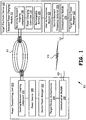
- FIG. 1 is a block diagram illustrating a wireless power delivery system 101 that includes a power transmitting unit 103 and a target electronic device 115, wherein power is delivered wirelessly employing magnetic waves.
- the power delivery system 101 is used to deliver electric power to one or more target devices, and the target devices use the delivered power for operation or for recharging a battery or both.
- the power delivery system 101 includes the power transmitting unit 103, the target electronic device 115, and other target devices capable of receiving power being transmitted.
- the power transmitting unit 103 includes a power source 105 capable of generating power for power transmission and a sending resonant coupling component 131 capable of power transmission employing magnetic waves 111, such as a non-radiated magnetic field waves of a specified target resonant frequency.
- the power transmitting unit 103 is capable of dynamically tuning the power transmission to the target resonant frequency associated with the target electronic device 115, wherein the target resonant frequency is specified dynamically.
- the power transmitting unit also includes a communication module 110 operable to send a communication signal to the target electronic device 115 via the magnetic waves 111 and via Radio Frequency (RF) communications 113.
- the RF communications 113 may include Wireless Local Area Network (WLAN) communications such as IEEE 802.11x communications, Wireless Personal Area Network (WPAN) communications such as Bluetooth communications, cellular communications, proprietary interface communications, or other RF communication techniques.
- WLAN Wireless Local Area Network
- WPAN Wireless Personal Area Network
- the communication module 110 may also include a wired communication link, e.g., Local Area Network (LAN) such as Ethernet, Cable Modem, Wide Area Network (WAN) and/or other wired communication means.
- LAN Local Area Network
- WAN Wide Area Network
- the wired communication link could provide a high speed uplink to the Internet.
- the target electronic device 115 includes a resonant power charging module 117, a user authorization module 121, a source resonant frequency selector 123, a communication module 125, and a target device power manager 127.
- the resonant power charging module 117 includes a receiving resonant coupling component 141, a power charging controller 119, and a rechargeable battery 129.
- the receiving resonant coupling component 141 also sometimes referred to as a receiving resonant charging component, is used to receive the power transmissions provided by the power transmitting unit 113 employing the target resonant frequency.
- the target electronic device 115 employs the received power for operation of the target electronic device 115 as well as for charging the rechargeable battery 129 in the target electronic device 115.
- the power delivery system 101 employs the sending resonant coupling component 113 of the power transmitting unit 103 to generate magnetic fields that are used to transmit power to the target devices, such as the target electronic device 115.
- the sending resonant coupling component 113 includes a resonant coil that fills the space around it with a non-radiated magnetic field oscillating at the target resonant frequency that is received by the target electronic device 115 employing the receiving resonant coupling component 141.
- the target device also includes a communication module operable 125 to communicate with the communication module 110 of the power transmitting unit 103 via the magnetic coupling and via RF communications.
- the power transmitting unit 103 that includes the power source 105 and the target electronic device 115 are communicatively coupled with each other during the resonant power delivery from the power source 105 to the target electronic device 115.
- the resonant coupling is achieved wirelessly using a 'wireless field' 111, which is non-radiated magnetic field in some embodiments.
- the 'wireless field' 111 is the power delivery channel and a 'wireless link' 113 is the control signal channel.
- communicating the power and a control signal are conducted employing the same frequency, or in other words, on the same channel, i.e. the wireless field 111.
- the power link such as the magnetic field
- the control signal and the normal communication
- the normal function operation takes place in separate channels.
- the power transmitting unit 103 is implemented in the base station of a mobile phone, where the normal communication operations with the mobile phone (from the base station), resonant power delivery, and the control signal transmission are all conducted between the mobile phone (as a target electronic device) and the base station employing different channels.
- the power source 105 is a module which generates the required power to be transmitted in a non-radiated magnetic or radiated magnetic mode, employing an essentially 'wireless means' 111.
- the power source 105 provides power to the sending resonant coupling component 131 which transmits it, for example, creating a non-radiated magnetic field.
- a source power manager 107 manages the wireless power transmission.
- the power source 105 generates an alternating current signal that is sufficiently power amplified and radiated using highly directional antenna in the direction of the target device 115.
- the required directionality for the power transmitted is achieved using an antenna array or a dish antenna, as appropriate.
- the resonant power charging module 117 of the target electronic device 115 includes the receiving resonant coupling component 141 that is capable of receiving the transmitted power.
- receiving resonant coupling component 141 includes a resonating coil and associated tuning elements such as capacitors.
- Isolation of the resonating circuitry of the receiving resonant coupling component 141 from other internal circuitry of the target electronic device 115 is supported, such as by the use of a buffer (isolation) amplifier, a diode, and capacitor voltage multiplier.
- the diode and the capacitor voltage multiplier are part of the resonating (antenna) circuitry of the receiving resonant coupling component 141.
- the required high quality factor and the resonant effect are achieved through the right choice of the diode, the capacitors, etc.
- voltage multipliers in the resonant power charging module 117 builds up the required voltage across a capacitor array to achieve the recharging of the rechargeable battery 129 of the target electronic device 115.
- the power charging controller 119 regulates the electric charge that flows into the rechargeable battery 129.
- the power charging controller 119 of the resonant power charging module 117 senses the battery voltage for its high voltage limit or the low voltage limits to stop charging or start charging, respectively.
- the high voltage limit protects the battery and the low voltage limit initiates a resonant power request that results in the subsequent battery charging operation.
- the user authorization module 121 facilitates the authentication of the target electronic device 115, for resonant power delivery, with the target device authenticator 109 of the power transmitting unit 103. During resonant power delivery the user authorization module 121 exchanges the authentication information with the power transmitting unit 103.
- the power transmitting unit 103 compares the information (or a computed value thereof) with the subscriber's information in its database accessed by the target device authenticator 109. If the match is determined, then resonant power delivery is initiated.
- the authentication is followed by optional frequency selection and directional adjustments of a non-radiated magnetic field in the direction of the target electronic device 115. In a related embodiment, the magnetic field steering is done based on the analysis of the determined or perceived location (egg. employing arrival direction) of the target electronic device 115.
- the source resonant frequency selector 123 provides a tuning mechanism in order to achieve the required resonant coupling effect. For example, it facilitates the tuning of capacitors where capacitors are used for tuning.
- Some tuning capacitors are voltage controlled, and they are basically, diode varactors. The tuning voltage is automatically adjusted to achieve the optimum reception from an antenna/ resonant coupling mechanism such as coils.
- the communicating module 125 facilitates the normal communication functionality of the target electronic device 115. It consumes the battery power when powered using the rechargeable battery 129.
- the power control communication that takes place between the target electronic device 115 and the power transmitting unit 103 during the resonant charging request, etc. is also performed using the communication module 125.
- a power control signal exchange operation is required for the authentication of the target electronic device 115 before a successful resonant power delivery.
- the target device power manager 127 manages the battery level of the rechargeable battery 129 by regulating the battery discharge and by initiating resonant power charge operation. For example, it monitors the battery level of the rechargeable battery 129 and initiates its recharge employing power delivered via resonant magnetic field.
- the battery charge (power in the battery) of the rechargeable battery 129 has to be replenished before the battery voltage falls below a threshold limit or before its power level falls below an acceptable level. If the battery voltage falls below a threshold limit, the critical part of the target electronic device 115 is likely to loose power supply, because the battery fails to operate. This situation is avoided with constant monitoring of battery levels and automatic triggering of recharge operations. Thus battery recharging and voltage restoration is automated and does not require any human intervention charge the rechargeable battery 129.
- the target device power manager 127 facilitates battery level monitoring and automatic recharge triggering.
- the target device power manager 127 tracks the total charging time, amount of charge delivered, etc.
- the amount of charge acquired by the rechargeable battery 129 is communicated to the power transmitting unit 103.
- the source power manager 107 conducts similar monitoring function associated with power management from the power transmitting unit 103.
- the target device authenticator 109 authenticates the resonant power requests made by the target electronic device 115, and works in coordination with the user authorization module 121 of the target electronic device 115.
- a rechargeable electronic device such as the target electronic device 115, typically includes the rechargeable battery 129.
- the rechargeable electronic device authenticates with the power transmitting unit 103 and receives a token that is used for subsequent communication and power charging (in one or more charging sessions).
- the rechargeable electronic device requests the power transmitting unit 103 for power, with the power to be transmitted employing non-radiated magnetic field waves of a target resonant frequency.
- the rechargeable electronic device 115 receives power transmitted over non-radiated magnetic field waves of the target resonant frequency from the power transmitting unit 103. It recharges the rechargeable battery 129 of the rechargeable electronic device 115.
- the power source 105 is operable to source alternating current power and the sending resonant coupling component 131 is operable to couple the alternating current power to a coil for wireless power transmission by a non-radiated magnetic field at a target resonant frequency.
- the power transmitting unit 103 is capable of dynamically tuning the wireless power transmission to the target resonant frequency wherein the target resonant frequency is specified dynamically.
- the communication module 110 is operable to couple the communication signal to the non-radiated magnetic field 111.
- the sending resonant coupling component 131 forms the non-radiated magnetic field 111 substantially omni-directionally.
- the communication module 110 is operable to communicate the target resonant frequency to the target device.
- the power transmitting unit 103 may adjust the target resonant frequency based upon feedback received from the target device 115 via the communication module 110.
- the communication module 110 may communicate with the target device 115 in an RF spectrum via the communication module 125 of the target device 115.
- the communication module 110 may communicate the target resonant frequency to the target device via the RF interface.
- the RF interface may also be operable to receive data from the target device that includes at least one of a target device identity, target device billing information, target device power receipt level(s), and a target device battery charge state.
- the RF interface may be operable to receive a request for power delivery from the target device and also to receive authentication information from the target device.
- the power transmitting unit may be operable to select the target resonant frequency based upon the target device authentication information.
- the power transmitting unit may also include a token generator that generates a token for delivery to the target device during a target device registration operation. The power transmitting unit is then operable to authenticate the target device during subsequent power transmission operations based partially on the token.
- the token generator may include a pseudorandom number generator operable to generate the token. With these operations, the power transmitting unit may be operable to deliver power to the target device only after authenticating the target device.
- the target electronic device 115 having the rechargeable battery 129 may be operable to authenticate with the power transmitting unit 103 by receiving a token from the power transmitting unit, requesting power transmission by a non-radiated magnetic field from the power transmitting unit, receiving power non-radiated magnetic field at the target resonant frequency from the power transmitting unit and recharging the rechargeable battery 129.
- Recharging of the rechargeable battery 129 by the target electronic device 115 may include applying received power to a rechargeable battery, periodically sending a charging status to the power transmitting unit, monitoring the charging status until it exceeds a high charging limit, and communicating a request for termination of power delivery to the power transmitting unit when the high charging limit is reached.
- the token is may be communicated to the power transmitting unit along with the request for power transmission with the token updated and stored when a new token is communicated by the power transmitting unit.
- the rechargeable electronic device may authenticate with the power transmitting unit employing a username and password.
- FIG. 2 is a block diagram illustrating a power transmitting network that employs resonant magnetic coupling for wireless power transfer from a power source 203 to a magnetic resonant target device 211, in accordance with another embodiment.
- the power source 203 includes a magnetic resonant power charging circuitry 205, a source power manger 207, and a target device authenticator 209.
- the magnetic resonant power charging circuitry 205 includes a magnetic field source (such as coupling circuitry) and power generator / amplifier to generate a magnetic field and to power amplify that field, respectively.
- the power amplified magnetic field is used to setup a magnetic field in air using a solenoid (or a coil) as indicated by a plurality of magnetic filed lines 225, 227, and 229. These magnetic lines 225-229 are coupled with a magnetic resonant power charging module 213 of the magnetic resonant target device 211.
- a magnetic resonant power charging circuitry 213 converts the time varying magnetic flux linkages to the induced voltage across a resonating coil associated with a plurality of diodes, and a plurality of (special) capacitors.
- the voltage that is developed across the coil is rectified into DC form and stored in a special capacitor bank (array) resulting in voltage multiplier action.
- the power charging controller 215 controls the power charging operation of a rechargeable battery 233 in the magnetic resonant target device 211.
- the power charging controller 215 senses the low voltage limit and high voltage limit of the rechargeable battery 233. When the voltage levels falls below the preset low voltage limit the power charging controller 215 issues signal to the target device power manager 223. In response, the target device power manager 223 sends a power request to the power source 203. The power source 203 then sets up the necessary magnetic field / flux in the air for wireless power transmission. In the meantime the magnetic resonant target device 211 starts receiving the electric power converted from the magnetic flux linkages received by a coil associated with the magnetic resonant power charging circuitry 213. In one embodiment, the received magnetic power is converted into induced electric power, and then to a DC power using a rectifier and capacitor array. The DC power is used to charge the 'rechargeable battery' 233 when the voltage across the capacitor array builds up to a battery charging limit.
- the source power manager 207 ensures adequate magnetic power level required to setup magnetic flux. Also it facilitates focusing magnetic flux lines 225-229 in one particular direction, if necessary, so that the magnetic resonant target device 211 will have an effective coupling with the power source 203.
- the target device authenticator 209 receives the identity of the magnetic resonant target device 211 and verifies a user's authentication or user's subscription to a power charging service.
- the user authorization module 219 provides the identity information of the magnetic resonant target device 211 and information about a subscription if any (if necessary).
- the confirmation of the user's subscription is conducted by comparing information available with the target device authenticator 209 (or a database maintained or accessed by it) with the information provided by the user authorization module 219.
- the target device power manager 223 initiates a power request using a wireless link 231 between the power source 203 and the magnetic resonant target device 211.
- the power charging controller 215 provides information periodically during the resonant power charging to the target device power manager 223.
- the target device power manager 223 communicates with the power source 203 during the resonant power charging activity so as to provide continued verification of access - the power source 203 can therefore eliminate / avoid unauthorized power access (by an unauthorized device).
- the source resonant frequency selector 217 helps in making fine adjustments to the resonant operation, with synchronization to the incoming power signal frequency. This results in effective coupling between the power source 203 and the magnetic resonant target device 211 for an efficient resonant power transfer.
- An user authorization module 219 delivers the identity of the magnetic resonant target device 211 to the power source 203, as necessary.
- the identity is sent on the 'wireless link' 231.
- This information is processed by the target device authenticator 209.
- the power source 203 delivers the resonant power signal.
- different frequencies are assigned to a plurality of the magnetic resonant target devices.
- the assigned frequency value is configured into the magnetic resonant target device 211. Sending of this information to power source 203 with a request for power helps in resonant locking / effective resonant coupling by the power source 203 with magnetic resonant target device 211.
- the communication module 221 includes a circuit that sets up communication for the control operation between the magnetic resonant target device 211 and the power source 203. For example, it communicates with the power source 203 via its communication module 212 on the standard pre-assigned frequency using the wireless link 231.
- FIG. 3 is a flowchart illustrating resonant power transfer operations performed using the power system of FIG. 1 wherein a wireless power transmitting unit 103 transmits power to the target electronic device 115 in accordance with an embodiment.
- the target electronic device 115 of FIG. 1 determines that power needs to be charged into the rechargeable battery 129.
- the target electronic device 115 communicates a request for resonant power signal to the power transmitting unit 103.
- the target electronic device 115 sends its identity and its (tuned) resonant frequency information to the power transmitting unit 103.
- the power transmitting unit 103 requests the current power level, billing information, etc. from the target electronic device 115.
- the target electronic device 115 sends the requested information to the power transmitting unit 103 in the next block 309.
- the power transmitting unit 103 then generates power employing the requested resonant frequency and delivers it in the form of magnetic field / waves at the next block 311.
- the magnetic field is in non-radiated mode, while in another, it is in radiated mode.
- the power transmitting unit 103 and the target electronic device 115 periodically exchange information on the current status of the battery charge during the resonant battery charge operation at the next block 313.
- the target electronic device 115 When the battery is charged completely (fully charged) at block 315 the target electronic device 115 communicates this status so that the power transmitting unit 103 can disconnect the power transmission (magnetic coupling). At this point of time the power transmitting unit 103 has the details of the amount of power delivered to the target electronic device 115. This information is used for metering and subsequent billing. The resonant power charge operation ends at the next block 317.
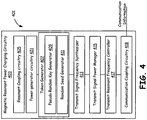
- FIG. 4 is a block diagram illustrating the magnetic resonant power charging circuitry 205 of FIG. 2 that is used to transmit power to multiple target devices located in a current direction of a non-radiated magnetic field / beam. Each of the target devices use randomly generated unique token for an authenticity check in accordance with one embodiment.
- the power source 203 has to manage the power delivery by generating a unique token for each of the target devices so as to track individual power consumption / delivery.
- the exchange of a token between the target device and the power source 203 authorizes that target device for receiving the power delivery on the same / common power resonant frequency.
- This technique helps when the multiple target devices are charging from a same / common magnetic resonant field / beam.
- the power source 203 and an individual target device, such as the magnetic resonant target device 211 synchronize token and related authentication information to authenticate a target device as a legitimate power receiver.
- This token based resonant power delivery can be used to serve all the target devices simultaneously.
- a generated token is communicated to the target device 211 employing encryption for security, confidentiality and non-repudiation.
- the decryption of the generated token at the target device requires a key that is communicated out-of-band or generated using a key generation technique.
- the key is generated in the target device employing a seed provided for generating keys using a random seed generator 411, the same seed being used by the pseudo random key generator 409 to generate the key in the token generator 407.
- the seed may be pre-configured in the target device or set initially by the user or the system. This key is thus generated in the target device or otherwise received as part of a configuration. In a related embodiment, a different key is generated for each communication / charging session using a seed provided to the target device. The key is generated in the target device randomly by using the seed sent by the random seed generator 411 of the magnetic resonant power charging circuitry 403.
- the transmit signal frequency synthesizer 413 synthesizes stable reference frequency for magnetic coupling. In one embodiment, all other frequencies used for power delivery are a function of this stable frequency.
- the power level of the synthesized signal is managed by the transmit signal power manager 415 so as to adequate power level is delivered. It also manages power delivery in a particular pattern or beam form.
- the power level of the magnetic field which is resonant coupled with the target device 211, 115 is sensed and amplified to a power level that is adequate for transmission to a maximum range. This functionality of the power level management is provided by the transmit signal power manager 415.
- the transmit resonant frequency controller 417 ensures that the magnetic power resonant field that charges the rechargeable battery of the target device 211, 215 is always stable. If for some reasons, the frequency drifts, then an automatic frequency controller mechanism is initiated to correct the magnetic coupling field frequency to its original predefined value.
- FIG. 5 is a block diagram illustrating the target device authenticator of FIG. 1 (and FIG. 2 ) which identifies and authenticates each of target devices using their unique identity during wireless resonant power charging operation.
- the target device authenticator 503 consists of a target device identification database 507, a communication protocol setup circuitry 509, a target device power metering circuitry 511 and a target device billing unit 513.
- the target device identification database 507 consists of the information of all subscribers who have subscribed with the power source 203 of FIG. 2 .
- the database information contains a pre-assigned identification number of the target device, relevant personal details of the user, a preferred magnetic resonant frequency for the target device, etc.
- the target device 211 communicates with the power source 203 during the power request it also sends it identity information so that the power source 203 cross-verifies with its target device identification database 507 contents. If the communicated information matches the database 507 contents then the resonant power delivery is initiated.
- the target device 211 tries to communicate with the power source 203 on its control channel 231 after setting up a communication protocol using the communication protocol setup circuitry 509.
- This circuitry sets up the target device 211 to communicate with the power source 103. This is required because, in general, the target device 211 performs some regular functionality other than charging, and in order to initiate the specific communication of the control operation for power transmission with the power source 203, it needs to be configured and it may require a protocol setup.
- the target device power metering circuitry 511 records the resonant power delivered to the target device 115, 211. This module is also coordinated with the source power manager 107, 207 during the resonant source power delivery. It essentially monitors the total battery charging duration at a possible rate of power delivery.
- the target device billing unit 513 performs the billing functionality for the service provided by the power source 203 to the target device 115, 211.
- FIG. 6 is the block diagram illustrating a resonant power charging module 117 of FIG. 1 that receives power on a single frequency on a wireless power & communication channel 111 in accordance with one embodiment.
- the target device resonant power charging module 603 consists of a receiving resonant coupling component 625, a resonant frequency seeking module 605, a target device authentication module 607, a power charging circuitry 609, a power request module 611 and a power charging controller 619.
- the receiving resonant coupling component 625 facilitates magnetic coupling, such as for non-radiated magnetic fields that are used for wireless power transmission. It has the antenna, tuning elements, etc. needed for coupling.
- the resonant frequency seeking module 605 tries to receive optimum incoming power signal by proper coupling by way of tuning the frequency of magnetic coupling. The maximization of the power signal reception is achieved by the automatic tuning of the resonant coupling circuit component, so that the tuning matches with the incoming magnetic field power frequency. Also the quality factor of the tuning elements is maximized by appropriately biasing the active devices to the low resistive region of operation.
- the target device authentication module 607 communicates with the power transmitting unit 103 or the power source 203 periodically to authenticate itself with it.
- the target device authenticator 109 of FIG. 1 and the target device authentication module 607 coordinate with each other in the process of resonant power transfer.
- the target device authenticator 109 identifies the target device by comparing the identity data received with the subscription data stored in the database 507 of FIG. 5 .
- the power charging circuitry 609 is the actual power signal charging circuitry that can charge a rechargeable battery or provide power for the operation of the target device. It provides DC rectifier diodes, capacitor array, battery charge control circuitry, voltage sensor circuitry, and the voltage regulation circuitry, as needed.
- the receiving resonant coupling component 625 (such as an antenna coil) is part of the power charging circuitry 609, in one embodiment Automatic tuning is achieved, such as using the varactor diode by controlling its bias voltage appropriately which works as a variable capacitor. If the rectifier/voltage multiplier circuit is not a part of the receiving resonant coupling component 625, then isolation between the resonant circuit and diode/capacitor voltage multiplier circuit is required for a sharp tuning with the incoming power signal, which is provided by the power charging circuitry 609.
- a power request module 611 is coordinated by the voltage sensing circuitry. When the voltage falls below a preset value the power request module 611 communicates with the power source 203, or the nearest power transmitting unit to the current location of target device. Subsequent to the power request made by the power request module 611 the resonant power delivery starts.
- the power charging controller 619 helps in maintaining the rechargeable battery charge at a safer limit for a smooth functioning of the target device 115, 211.
- the power charging controller 619 has a low voltage sensor 621 and a high voltage sensor 623.
- the low voltage sensor 621 monitor the low voltage limit of the rechargeable battery and the high voltage sensor 623 monitor the high voltage limit.
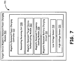
- FIG. 7 is the block diagram illustrating a target device magnetic resonant power charging module 703 used in a target device. It is used which in target devices to receive power through high frequency magnetic flux coupling resulting from the resonant magnetic fields of a particular frequency provided by a power source.
- the target device's magnetic resonant power charging module 703 consists of a magnetic resonant power charging controller circuitry 717 that includes a resonating receiving coil 705, a magnetic resonant target device authentication module 707, a magnetic resonant frequency seeking module 709, a magnetic resonant battery charging circuit 711, a low voltage sensor 719, and a high voltage sensor 721.
- the resonating receiving coil 705 is the coil on the magnetic resonant target device 211, capable of coupling with high frequency magnetic flux fields 225-229 of FIG. 2 .
- the magnetic flux induces a voltage across the resonating receiving coil 705.
- the voltage across the resonating receiving coil 705 is maximized by a tuning mechanism which includes this coil as part of it, in accordance with one embodiment.
- This tuning circuit has rectifier diodes for rectifying the magnetically induced AC voltage across the tuning circuit along with a variable capacitor (varactor diode).
- the rectified voltage in the form of DC is stored in an array of capacitors acting as voltage multiplier. The voltage from the voltage multiplier will charge the rechargeable battery 233 of FIG. 2 .
- the magnetic resonant target device authenticating module 707 sends the authentication information from the magnetic resonant target device 211 to the power source 203 of FIG. 2 during resonant power request.
- the target device authenticator 209 of FIG. 2 receives this information and authenticates the magnetic resonant target device 211 for the subsequent power delivery.
- the magnetic resonant frequency seeking module 709 has the functionality of maximizing the received power on the magnetic resonant target device 211 of FIG. 2 by automatic fine tuning of the resonating components.
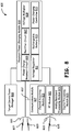
- FIG. 8 is a block diagram illustrating an embodiment of a target electronic device 115 of FIG. 1 receiving the power signal using the resonant power charging module 117.
- the communication module 125 of FIG. 1 consumes power from the rechargeable battery 129 of FIG. 1 , while the target device power manager 127 simultaneously coordinates the operation of resonant power charging of the rechargeable battery 129, in accordance with one aspect.
- An exemplary electronic device considered as the target device in FIG. 8 consists of a target device power manager 803, a resonant power charging module 839, and the communication module 817.
- the exemplary resonant power charging module 839 includes a power charge request circuit 805, a rectifier circuit 807, a voltage multiplier 809, a voltage regulator 811, a rechargeable battery 183 (129 of FIG. 1 repeated), and a power charging controller 815 (119 of FIG. 1 repeated).
- the power charge resonant circuit 805 is a tuned circuit that resonates with the incoming power signal. With the quality factor of the power charge resonant circuit 805 being quite large voltage builds up across it.
- the rectifier circuit 807 is made up of special diodes which rectifies the incoming RF signal and charges the capacitor array of the voltage multiplier 809.
- the rechargeable battery 813 starts charging.
- the power charging controller 815 monitors the battery voltage. When once the battery voltage level reaches its full charge limit the power charging controller 815 issues a signal to set high voltage limit flag monitored by the target device power manager 803 (127 of FIG. 1 repeated). Similarly when the voltage level falls below a preset low level the power charging controller 815 issues a signal that sets a low voltage limit flag monitored / read by 'target device power manager' 803.
- the target device power manager 803 Upon reading the high voltage limit flag the target device power manager 803 sends a power cutoff request to the power transmitting unit 103 on the control channel 113. By reading the low voltage limit flag the target device power manager 803 sends a power request to the power transmitting unit 103. Further the target device power manager 803 monitors the rechargeable battery voltage during the power delivery to communication module 817 for its normal operation. The power charging controller 815 senses the low voltage limit and sets the low voltage limit flag. The target device power manager 803 reads the low voltage limit flag and request with power transmitting unit 103 of FIG. 1 for the delivery of the resonant power signal. The target device power manager 803 tries to maintain the constant supply voltage by controlling the duty cycle of the DC to DC converter based voltage regulator 811.
- the communication module 817 is powered by the rechargeable battery 813.
- the antenna 831 is used for both resonant power charging and normal communication operation. When used this way the dotted wired link 837 is used for the communication signal.
- the communication circuit needs to be protected or cutoff from the resonant power signal. This configuration will disturb the resonant tuning of target device by lowering the quality factor of the tuned circuit.
- another antenna 833 with the wireless link 835 is employed exclusively for communication purposes.
- the sub-modules of the communication module 817 are the channel acquiring module 819, an RF communication module 821, an analog baseband processing module 823, and the digital processing module 825.
- the channel acquiring module 819 facilitates the function of acquiring different communication channel as in a mobile phone.
- the RF communication module 821 performs the function of modulation, demodulation, amplification of RF signal, etc.
- the analog baseband processing module 823 processes the baseband signal.
- the digital processing module 825 performs the digital signal processing functionality, which includes encryption/decryption of the digital data, etc.
- FIG. 9 is a flowchart illustrating actions performed by the target device power manager of FIG. 1 and FIG. 2 during the resonant power charging operation.
- the target device power manager 127 of FIG. 1 starts operations at a start block 903. Then, at a next block 904, it authenticates with the power transmitting unit 103 of FIG. 1 for its subscription.
- the target device power manager 127 of FIG. 1 sends the power charging request for the power transmitting unit 103 of FIG. 1 at a subsequent block 905.
- the power transmitting unit 103 of FIG. 1 transmits the power charging signal to the target electronic device 115.
- the target device power manager 127 of FIG. 1 then monitors the charging status and updates it to the power transmitting unit 103 at a next block 907.
- the target device power manager 127 of FIG. 1 monitors the high voltage limit corresponding to the full battery charge condition and sets the high voltage flag. The target device power manager 127 then tests the high voltage flag at a next decision block 911. If the test returns false then the target device power manager 127 continues the battery charging operation by going back to the next block 907.
- the target device power manager 127 of FIG. 1 communicates a request for the resonant power cutoff at a next block 913. It then continues monitoring the discharge rate of the battery and adjusts the duty cycle of the voltage regulator 811 of FIG. 8 at a next block 915. It continues sensing the low voltage limit periodically at a next block 917. The target device power manager then reads the low voltage limit flag and tests the low voltage limit flag at a next block 919. If the test returns false the target device power manager 127 performs the battery voltage monitoring operation at a next block 915, else it goes back to the next block 904 for authentication and subsequent resonant power charging.
- FIG. 10 is a block diagram illustrating structure 1000 for communication coupling in a power transmitting unit.
- the structure includes data formatting and modulation circuitry 1002, and one or more of combining circuitry 1004 and 1008.
- the data formatting and modulating circuitry receives data and control information, formats such information, and modulates the information into an analog information signal in a selected spectrum. This spectrum may be centered at the target resonant frequency or at another frequency.
- the analog information signal is coupled to the power signal of the target resonant frequency for transmission to via coil(s) 1010. Depending upon the embodiment it may be preferable to couple the analog information signal prior to or subsequent to the magnetic resonant power charging circuit.
- the signal incoming to the combining circuitry 1004 is of a selected target resonant frequency but at a low amplitude it may be preferable to couple the analog information signal by combining circuitry 1004. However, if the magnetic resonant power charging circuit may degrade the analog information signal after coupling, it may be desirable to couple the analog information signal via combing circuitry 1008.
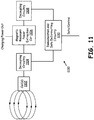
- FIG. 11 is a block diagram illustrating structure 1100 for communication de-coupling in a target device. Note that the structure 1100 of FIG. 11 could also be included in the power transmitting unit as well.
- the structure 1100 of FIG. 11 includes coils 1102, decoupling circuitry 1104 and/or 1108, magnetic resonant power extraction circuit 1106 and demodulation and data de-formatting circuitry 1110. Note that the decoupling circuitry 1104 and/or 1108 may decouple an analog information signal from the signal received by the coil(s) 1102 before or after the magnetic resonant power extraction circuit 1106.
- the demodulation and de-formatting circuitry operates to extract data and control information from a received analog information signal and may include down conversion, filtering, amplification, demodulation, decoding, and various other functional structures.
- circuit and “circuitry” as used herein may refer to an independent circuit or to a portion of a multifunctional circuit that performs multiple underlying functions.
- processing circuitry may be implemented as a single chip processor or as a plurality of processing chips.
- a first circuit and a second circuit may be combined in one embodiment into a single circuit or, in another embodiment, operate independently perhaps in separate chips.
- chip refers to an integrated circuit. Circuits and circuitry may comprise general or specific purpose hardware, or may comprise such hardware and associated software such as firmware or object code.
- the terms “substantially” and “approximately” provides an industry-accepted tolerance for its corresponding term and/or relativity between items. Such an industry-accepted tolerance ranges from less than one percent to fifty percent and corresponds to, but is not limited to, component values, integrated circuit process variations, temperature variations, rise and fall times, and/or thermal noise. Such relativity between items ranges from a difference of a few percent to magnitude differences.
- the term(s) "coupled to” and/or “coupling” and/or includes direct coupling between items and/or indirect coupling between items via an intervening item (e.g., an item includes, but is not limited to, a component, an element, a circuit, and/or a module) where, for indirect coupling, the intervening item does not modify the information of a signal but may adjust its current level, voltage level, and/or power level.
- an intervening item e.g., an item includes, but is not limited to, a component, an element, a circuit, and/or a module
- inferred coupling includes direct and indirect coupling between two items in the same manner as “coupled to.”
- operble to indicates that an item includes one or more of power connections, input(s), output(s), etc., to perform one or more its corresponding functions and may further include inferred coupling to one or more other items.
- associated with includes direct and/or indirect coupling of separate items and/or one item being embedded within another item.
- compares favorably indicates that a comparison between two or more items, signals, etc., provides a desired relationship. For example, when the desired relationship is that signal 1 has a greater magnitude than signal 2, a favorable comparison may be achieved when the magnitude of signal 1 is greater than that of signal 2 or when the magnitude of signal 2 is less than that of signal 1.
Landscapes
- Engineering & Computer Science (AREA)
- Computer Networks & Wireless Communication (AREA)
- Business, Economics & Management (AREA)
- Power Engineering (AREA)
- Signal Processing (AREA)
- Accounting & Taxation (AREA)
- Health & Medical Sciences (AREA)
- Strategic Management (AREA)
- General Physics & Mathematics (AREA)
- Theoretical Computer Science (AREA)
- Physics & Mathematics (AREA)
- Economics (AREA)
- Finance (AREA)
- General Business, Economics & Management (AREA)
- General Health & Medical Sciences (AREA)
- Human Resources & Organizations (AREA)
- Marketing (AREA)
- Primary Health Care (AREA)
- Tourism & Hospitality (AREA)
- Water Supply & Treatment (AREA)
- Public Health (AREA)
- Charge And Discharge Circuits For Batteries Or The Like (AREA)
- Near-Field Transmission Systems (AREA)
Claims (9)
- Système d'alimentation électrique permettant de distribuer sans fil de l'énergie électrique à un dispositif cible (115) et de distribuer un signal de communication au dispositif cible (115), le système d'alimentation électrique comprenant :une unité de transmission d'énergie (103) comprenant :une source d'énergie (105) fonctionnant de manière à fournir une alimentation en courant alternatif ;un composant de couplage résonnant d'envoi (131) fonctionnant de manière à coupler l'alimentation en courant alternatif à une bobine permettant une transmission d'énergie sans fil par un champ magnétique non rayonné à une fréquence résonnante cible ;l'unité de transmission d'énergie (103) capable de régler de manière dynamique la transmission d'énergie sans fil à la fréquence résonnante cible, dans lequel la fréquence résonnante cible est spécifiée de manière dynamique ;caractérisé en ce quele système d'alimentation électrique comprend en outre un module de communication (212) couplé à l'unité de transmission d'énergie (103) et fonctionnant de manière à coupler le signal de communication au champ magnétique non rayonné ;le module de communication (212) comprend en outre une interface de fréquence radio, RF, fonctionnant de manière à communiquer avec le dispositif cible (115) dans un spectre RF ;le module de communication (212) fonctionnant de manière à envoyer un signal de communication au dispositif cible (115) par le biais du champ magnétique non rayonné et par le biais des communications RF; etl'interface RF fonctionne de manière à recevoir une demande pour l'alimentation électrique à partir du dispositif cible (115).
- Système d'alimentation électrique selon la revendication 1, dans lequel le composant de couplage résonnant d'envoi (131) comprend la bobine qui fonctionne de manière à fournir le champ magnétique non rayonné à la fréquence résonnante cible.
- Système d'alimentation électrique selon la revendication 1, dans lequel le module de communication (212) fonctionne de manière à communiquer la fréquence résonnante cible au dispositif cible (115).
- Système d'alimentation électrique selon la revendication 1, dans lequel l'unité de transmission d'énergie (103) fonctionne de manière à régler la fréquence résonante cible sur la base d'un-retour reçu à partir du dispositif cible (115) par le biais du module de communication (212).
- Système d'alimentation électrique selon la revendication 1, dans lequel le module de communication (212) fonctionne de manière à communiquer la fréquence résonnante cible au dispositif cible (115) par le biais de l'interface RF.
- Système d'alimentation électrique selon la revendication 1, dans lequel l'interface RF fonctionne de manière à recevoir des données à partir du dispositif cible (115) qui comprend au moins un élément parmi :une identité du dispositif cible ;des informations de facturation du dispositif cible ;un ou des niveaux de réception d'énergie du dispositif cible ; etun état de charge de la batterie du dispositif cible.
- Système d'alimentation électrique selon la revendication 1, dans lequel l'interface RF fonctionne de manière à recevoir des informations d'authentification à partir du dispositif cible (115).
- Système d'alimentation électrique selon la revendication 7, dans lequel l'unité de transmission d'énergie (103) fonctionne de manière à sélectionner la fréquence résonnante cible sur la base des informations d'authentification du dispositif cible.
- Procédé permettant de distribuer sans fil de l'énergie électrique et un signal de communication à un dispositif cible (115), comprenant :la génération d'une alimentation en courant alternatif ;le couplage de l'alimentation en courant alternatif à une bobine pour fournir une transmission d'énergie sans fil par un champ magnétique non rayonné à une fréquence résonnante cible vers un dispositif cible (115) ; etle réglage de manière dynamique de la transmission d'énergie sans fil à la fréquence résonnante cible, dans lequel la fréquence résonnante cible est spécifiée de manière dynamique ;caractérisé parle couplage du signal de communication au champ magnétique non rayonné ;la communication avec le dispositif cible par le biais du champ magnétique non rayonné ;la communication avec le dispositif cible par le biais de l'interface de fréquence radio ; etla réception d'une demande d'alimentation électrique à partir du dispositif cible (115) par le biais de l'interface de fréquence radio.
Priority Applications (1)
| Application Number | Priority Date | Filing Date | Title |
|---|---|---|---|
| EP19163722.2A EP3582367B1 (fr) | 2008-08-05 | 2009-07-20 | Chargement de puissance résonante sans fil intégrée et canal de communication |
Applications Claiming Priority (2)
| Application Number | Priority Date | Filing Date | Title |
|---|---|---|---|
| US8638008P | 2008-08-05 | 2008-08-05 | |
| US12/241,245 US8111042B2 (en) | 2008-08-05 | 2008-09-30 | Integrated wireless resonant power charging and communication channel |
Related Child Applications (1)
| Application Number | Title | Priority Date | Filing Date |
|---|---|---|---|
| EP19163722.2A Division EP3582367B1 (fr) | 2008-08-05 | 2009-07-20 | Chargement de puissance résonante sans fil intégrée et canal de communication |
Publications (3)
| Publication Number | Publication Date |
|---|---|
| EP2151907A2 EP2151907A2 (fr) | 2010-02-10 |
| EP2151907A3 EP2151907A3 (fr) | 2013-11-06 |
| EP2151907B1 true EP2151907B1 (fr) | 2019-03-20 |
Family
ID=41449868
Family Applications (2)
| Application Number | Title | Priority Date | Filing Date |
|---|---|---|---|
| EP09009388.1A Active EP2151907B1 (fr) | 2008-08-05 | 2009-07-20 | Chargement de puissance résonante sans fil intégrée et canal de communication |
| EP19163722.2A Active EP3582367B1 (fr) | 2008-08-05 | 2009-07-20 | Chargement de puissance résonante sans fil intégrée et canal de communication |
Family Applications After (1)
| Application Number | Title | Priority Date | Filing Date |
|---|---|---|---|
| EP19163722.2A Active EP3582367B1 (fr) | 2008-08-05 | 2009-07-20 | Chargement de puissance résonante sans fil intégrée et canal de communication |
Country Status (5)
| Country | Link |
|---|---|
| US (4) | US8111042B2 (fr) |
| EP (2) | EP2151907B1 (fr) |
| KR (1) | KR101065738B1 (fr) |
| CN (1) | CN101645619B (fr) |
| TW (1) | TWI424653B (fr) |
Families Citing this family (444)
| Publication number | Priority date | Publication date | Assignee | Title |
|---|---|---|---|---|
| AU2003303597A1 (en) | 2002-12-31 | 2004-07-29 | Therasense, Inc. | Continuous glucose monitoring system and methods of use |
| US8771183B2 (en) | 2004-02-17 | 2014-07-08 | Abbott Diabetes Care Inc. | Method and system for providing data communication in continuous glucose monitoring and management system |
| US7587287B2 (en) * | 2003-04-04 | 2009-09-08 | Abbott Diabetes Care Inc. | Method and system for transferring analyte test data |
| US7679407B2 (en) * | 2003-04-28 | 2010-03-16 | Abbott Diabetes Care Inc. | Method and apparatus for providing peak detection circuitry for data communication systems |
| US7722536B2 (en) * | 2003-07-15 | 2010-05-25 | Abbott Diabetes Care Inc. | Glucose measuring device integrated into a holster for a personal area network device |
| WO2005119524A2 (fr) | 2004-06-04 | 2005-12-15 | Therasense, Inc. | Architecture hote-client de soins pour le diabete et systemes de gestion de donnees |
| US8029441B2 (en) | 2006-02-28 | 2011-10-04 | Abbott Diabetes Care Inc. | Analyte sensor transmitter unit configuration for a data monitoring and management system |
| US9788771B2 (en) | 2006-10-23 | 2017-10-17 | Abbott Diabetes Care Inc. | Variable speed sensor insertion devices and methods of use |
| US9351669B2 (en) | 2009-09-30 | 2016-05-31 | Abbott Diabetes Care Inc. | Interconnect for on-body analyte monitoring device |
| US7545272B2 (en) | 2005-02-08 | 2009-06-09 | Therasense, Inc. | RF tag on test strips, test strip vials and boxes |
| US9596031B2 (en) * | 2005-03-01 | 2017-03-14 | Alexander Ivan Soto | System and method for a subscriber-powered network element |
| US7768408B2 (en) | 2005-05-17 | 2010-08-03 | Abbott Diabetes Care Inc. | Method and system for providing data management in data monitoring system |
| US7825543B2 (en) * | 2005-07-12 | 2010-11-02 | Massachusetts Institute Of Technology | Wireless energy transfer |
| US7756561B2 (en) * | 2005-09-30 | 2010-07-13 | Abbott Diabetes Care Inc. | Method and apparatus for providing rechargeable power in data monitoring and management systems |
| US7583190B2 (en) * | 2005-10-31 | 2009-09-01 | Abbott Diabetes Care Inc. | Method and apparatus for providing data communication in data monitoring and management systems |
| US7620438B2 (en) | 2006-03-31 | 2009-11-17 | Abbott Diabetes Care Inc. | Method and system for powering an electronic device |
| US8219173B2 (en) | 2008-09-30 | 2012-07-10 | Abbott Diabetes Care Inc. | Optimizing analyte sensor calibration |
| US7801582B2 (en) | 2006-03-31 | 2010-09-21 | Abbott Diabetes Care Inc. | Analyte monitoring and management system and methods therefor |
| US9675290B2 (en) | 2012-10-30 | 2017-06-13 | Abbott Diabetes Care Inc. | Sensitivity calibration of in vivo sensors used to measure analyte concentration |
| US20080199894A1 (en) | 2007-02-15 | 2008-08-21 | Abbott Diabetes Care, Inc. | Device and method for automatic data acquisition and/or detection |
| US8123686B2 (en) | 2007-03-01 | 2012-02-28 | Abbott Diabetes Care Inc. | Method and apparatus for providing rolling data in communication systems |
| ES2461090T3 (es) | 2007-04-14 | 2014-05-16 | Abbott Diabetes Care Inc. | Procedimiento y aparato para proporcionar tratamiento y control de datos en un sistema de comunicación médica |
| CA2683959C (fr) | 2007-04-14 | 2017-08-29 | Abbott Diabetes Care Inc. | Procede et appareil pour realiser le traitement et la commande de donnees dans un systeme de communication medical |
| WO2008130898A1 (fr) | 2007-04-14 | 2008-10-30 | Abbott Diabetes Care, Inc. | Procédé et appareil pour réaliser le traitement et la commande de données dans un système de communication médical |
| WO2009096992A1 (fr) | 2007-04-14 | 2009-08-06 | Abbott Diabetes Care, Inc. | Procédé et appareil permettant le traitement et le contrôle des données dans un système de communication médical |
| US7928850B2 (en) | 2007-05-08 | 2011-04-19 | Abbott Diabetes Care Inc. | Analyte monitoring system and methods |
| US20080281179A1 (en) * | 2007-05-08 | 2008-11-13 | Abbott Diabetes Care, Inc. | Analyte monitoring system and methods |
| US8665091B2 (en) | 2007-05-08 | 2014-03-04 | Abbott Diabetes Care Inc. | Method and device for determining elapsed sensor life |
| US20080278332A1 (en) * | 2007-05-08 | 2008-11-13 | Abbott Diabetes Care, Inc. | Analyte monitoring system and methods |
| US8456301B2 (en) | 2007-05-08 | 2013-06-04 | Abbott Diabetes Care Inc. | Analyte monitoring system and methods |
| US8461985B2 (en) | 2007-05-08 | 2013-06-11 | Abbott Diabetes Care Inc. | Analyte monitoring system and methods |
| US8103471B2 (en) | 2007-05-14 | 2012-01-24 | Abbott Diabetes Care Inc. | Method and apparatus for providing data processing and control in a medical communication system |
| US8239166B2 (en) | 2007-05-14 | 2012-08-07 | Abbott Diabetes Care Inc. | Method and apparatus for providing data processing and control in a medical communication system |
| US9125548B2 (en) | 2007-05-14 | 2015-09-08 | Abbott Diabetes Care Inc. | Method and apparatus for providing data processing and control in a medical communication system |
| US8560038B2 (en) | 2007-05-14 | 2013-10-15 | Abbott Diabetes Care Inc. | Method and apparatus for providing data processing and control in a medical communication system |
| US8600681B2 (en) | 2007-05-14 | 2013-12-03 | Abbott Diabetes Care Inc. | Method and apparatus for providing data processing and control in a medical communication system |
| US8260558B2 (en) | 2007-05-14 | 2012-09-04 | Abbott Diabetes Care Inc. | Method and apparatus for providing data processing and control in a medical communication system |
| US10002233B2 (en) | 2007-05-14 | 2018-06-19 | Abbott Diabetes Care Inc. | Method and apparatus for providing data processing and control in a medical communication system |
| US8444560B2 (en) | 2007-05-14 | 2013-05-21 | Abbott Diabetes Care Inc. | Method and apparatus for providing data processing and control in a medical communication system |
| US8026382B2 (en) * | 2007-05-18 | 2011-09-27 | Heidi Kay | Lipid raft, caveolin protein, and caveolar function modulation compounds and associated synthetic and therapeutic methods |
| US8805530B2 (en) | 2007-06-01 | 2014-08-12 | Witricity Corporation | Power generation for implantable devices |
| US9421388B2 (en) | 2007-06-01 | 2016-08-23 | Witricity Corporation | Power generation for implantable devices |
| EP2171031B1 (fr) | 2007-06-21 | 2018-12-05 | Abbott Diabetes Care Inc. | Dispositifs et procédés de gestion de la santé |
| CN103251414B (zh) * | 2007-06-21 | 2017-05-24 | 雅培糖尿病护理公司 | 用于分析物水平的检测的设备 |
| US8160900B2 (en) | 2007-06-29 | 2012-04-17 | Abbott Diabetes Care Inc. | Analyte monitoring and management device and method to analyze the frequency of user interaction with the device |
| US8834366B2 (en) | 2007-07-31 | 2014-09-16 | Abbott Diabetes Care Inc. | Method and apparatus for providing analyte sensor calibration |
| US9300203B2 (en) | 2007-12-10 | 2016-03-29 | Clevx, Llc | Battery power supply with automatic load sensing |
| US20120049800A1 (en) * | 2010-08-25 | 2012-03-01 | Clevx, Llc | Power supply system with automatic sensing mechanism and method of operation thereof |
| WO2009140506A1 (fr) | 2008-05-14 | 2009-11-19 | Massachusetts Institute Of Technology | Transfert d'énergie sans fil, comprenant une amélioration vis-à-vis d'une interférence |
| US7826382B2 (en) | 2008-05-30 | 2010-11-02 | Abbott Diabetes Care Inc. | Close proximity communication device and methods |
| US20100034238A1 (en) * | 2008-08-05 | 2010-02-11 | Broadcom Corporation | Spread spectrum wireless resonant power delivery |
| US9473209B2 (en) * | 2008-08-20 | 2016-10-18 | Intel Corporation | Wireless power transfer apparatus and method thereof |
| US9601266B2 (en) | 2008-09-27 | 2017-03-21 | Witricity Corporation | Multiple connected resonators with a single electronic circuit |
| US9396867B2 (en) | 2008-09-27 | 2016-07-19 | Witricity Corporation | Integrated resonator-shield structures |
| US8901779B2 (en) * | 2008-09-27 | 2014-12-02 | Witricity Corporation | Wireless energy transfer with resonator arrays for medical applications |
| US8963488B2 (en) | 2008-09-27 | 2015-02-24 | Witricity Corporation | Position insensitive wireless charging |
| US8947186B2 (en) | 2008-09-27 | 2015-02-03 | Witricity Corporation | Wireless energy transfer resonator thermal management |
| US8928276B2 (en) | 2008-09-27 | 2015-01-06 | Witricity Corporation | Integrated repeaters for cell phone applications |
| US8922066B2 (en) | 2008-09-27 | 2014-12-30 | Witricity Corporation | Wireless energy transfer with multi resonator arrays for vehicle applications |
| US8723366B2 (en) | 2008-09-27 | 2014-05-13 | Witricity Corporation | Wireless energy transfer resonator enclosures |
| US8304935B2 (en) * | 2008-09-27 | 2012-11-06 | Witricity Corporation | Wireless energy transfer using field shaping to reduce loss |
| US8912687B2 (en) | 2008-09-27 | 2014-12-16 | Witricity Corporation | Secure wireless energy transfer for vehicle applications |
| US9105959B2 (en) | 2008-09-27 | 2015-08-11 | Witricity Corporation | Resonator enclosure |
| US8400017B2 (en) | 2008-09-27 | 2013-03-19 | Witricity Corporation | Wireless energy transfer for computer peripheral applications |
| US8587155B2 (en) * | 2008-09-27 | 2013-11-19 | Witricity Corporation | Wireless energy transfer using repeater resonators |
| US20110043049A1 (en) * | 2008-09-27 | 2011-02-24 | Aristeidis Karalis | Wireless energy transfer with high-q resonators using field shaping to improve k |
| US8441154B2 (en) | 2008-09-27 | 2013-05-14 | Witricity Corporation | Multi-resonator wireless energy transfer for exterior lighting |
| US8471410B2 (en) | 2008-09-27 | 2013-06-25 | Witricity Corporation | Wireless energy transfer over distance using field shaping to improve the coupling factor |
| US9744858B2 (en) | 2008-09-27 | 2017-08-29 | Witricity Corporation | System for wireless energy distribution in a vehicle |
| US8957549B2 (en) | 2008-09-27 | 2015-02-17 | Witricity Corporation | Tunable wireless energy transfer for in-vehicle applications |
| US8569914B2 (en) | 2008-09-27 | 2013-10-29 | Witricity Corporation | Wireless energy transfer using object positioning for improved k |
| US8692410B2 (en) * | 2008-09-27 | 2014-04-08 | Witricity Corporation | Wireless energy transfer with frequency hopping |
| US8901778B2 (en) | 2008-09-27 | 2014-12-02 | Witricity Corporation | Wireless energy transfer with variable size resonators for implanted medical devices |
| US8772973B2 (en) * | 2008-09-27 | 2014-07-08 | Witricity Corporation | Integrated resonator-shield structures |
| US8324759B2 (en) * | 2008-09-27 | 2012-12-04 | Witricity Corporation | Wireless energy transfer using magnetic materials to shape field and reduce loss |
| WO2010036980A1 (fr) | 2008-09-27 | 2010-04-01 | Witricity Corporation | Systèmes de transfert d'énergie sans fil |
| US8692412B2 (en) * | 2008-09-27 | 2014-04-08 | Witricity Corporation | Temperature compensation in a wireless transfer system |
| US8461721B2 (en) | 2008-09-27 | 2013-06-11 | Witricity Corporation | Wireless energy transfer using object positioning for low loss |
| US8629578B2 (en) | 2008-09-27 | 2014-01-14 | Witricity Corporation | Wireless energy transfer systems |
| US8482158B2 (en) | 2008-09-27 | 2013-07-09 | Witricity Corporation | Wireless energy transfer using variable size resonators and system monitoring |
| US8461722B2 (en) | 2008-09-27 | 2013-06-11 | Witricity Corporation | Wireless energy transfer using conducting surfaces to shape field and improve K |
| US20110074346A1 (en) * | 2009-09-25 | 2011-03-31 | Hall Katherine L | Vehicle charger safety system and method |
| US8497601B2 (en) | 2008-09-27 | 2013-07-30 | Witricity Corporation | Wireless energy transfer converters |
| US9601261B2 (en) | 2008-09-27 | 2017-03-21 | Witricity Corporation | Wireless energy transfer using repeater resonators |
| US8686598B2 (en) | 2008-09-27 | 2014-04-01 | Witricity Corporation | Wireless energy transfer for supplying power and heat to a device |
| US9601270B2 (en) | 2008-09-27 | 2017-03-21 | Witricity Corporation | Low AC resistance conductor designs |
| US8410636B2 (en) | 2008-09-27 | 2013-04-02 | Witricity Corporation | Low AC resistance conductor designs |
| US8466583B2 (en) | 2008-09-27 | 2013-06-18 | Witricity Corporation | Tunable wireless energy transfer for outdoor lighting applications |
| US8907531B2 (en) | 2008-09-27 | 2014-12-09 | Witricity Corporation | Wireless energy transfer with variable size resonators for medical applications |
| US8487480B1 (en) | 2008-09-27 | 2013-07-16 | Witricity Corporation | Wireless energy transfer resonator kit |
| US8937408B2 (en) | 2008-09-27 | 2015-01-20 | Witricity Corporation | Wireless energy transfer for medical applications |
| US9093853B2 (en) | 2008-09-27 | 2015-07-28 | Witricity Corporation | Flexible resonator attachment |
| US8933594B2 (en) | 2008-09-27 | 2015-01-13 | Witricity Corporation | Wireless energy transfer for vehicles |
| US8598743B2 (en) | 2008-09-27 | 2013-12-03 | Witricity Corporation | Resonator arrays for wireless energy transfer |
| US9577436B2 (en) | 2008-09-27 | 2017-02-21 | Witricity Corporation | Wireless energy transfer for implantable devices |
| US9515494B2 (en) | 2008-09-27 | 2016-12-06 | Witricity Corporation | Wireless power system including impedance matching network |
| US9184595B2 (en) | 2008-09-27 | 2015-11-10 | Witricity Corporation | Wireless energy transfer in lossy environments |
| US8946938B2 (en) | 2008-09-27 | 2015-02-03 | Witricity Corporation | Safety systems for wireless energy transfer in vehicle applications |
| US8476788B2 (en) | 2008-09-27 | 2013-07-02 | Witricity Corporation | Wireless energy transfer with high-Q resonators using field shaping to improve K |
| US8669676B2 (en) | 2008-09-27 | 2014-03-11 | Witricity Corporation | Wireless energy transfer across variable distances using field shaping with magnetic materials to improve the coupling factor |
| US9160203B2 (en) | 2008-09-27 | 2015-10-13 | Witricity Corporation | Wireless powered television |
| US8552592B2 (en) * | 2008-09-27 | 2013-10-08 | Witricity Corporation | Wireless energy transfer with feedback control for lighting applications |
| US9246336B2 (en) | 2008-09-27 | 2016-01-26 | Witricity Corporation | Resonator optimizations for wireless energy transfer |
| US9544683B2 (en) | 2008-09-27 | 2017-01-10 | Witricity Corporation | Wirelessly powered audio devices |
| US8643326B2 (en) | 2008-09-27 | 2014-02-04 | Witricity Corporation | Tunable wireless energy transfer systems |
| US9106203B2 (en) | 2008-09-27 | 2015-08-11 | Witricity Corporation | Secure wireless energy transfer in medical applications |
| US9318922B2 (en) | 2008-09-27 | 2016-04-19 | Witricity Corporation | Mechanically removable wireless power vehicle seat assembly |
| US9065423B2 (en) | 2008-09-27 | 2015-06-23 | Witricity Corporation | Wireless energy distribution system |
| US20160087687A1 (en) * | 2008-09-27 | 2016-03-24 | Witricity Corporation | Communication in a wireless power transmission system |
| US8587153B2 (en) | 2008-09-27 | 2013-11-19 | Witricity Corporation | Wireless energy transfer using high Q resonators for lighting applications |
| US9035499B2 (en) | 2008-09-27 | 2015-05-19 | Witricity Corporation | Wireless energy transfer for photovoltaic panels |
| US8461720B2 (en) * | 2008-09-27 | 2013-06-11 | Witricity Corporation | Wireless energy transfer using conducting surfaces to shape fields and reduce loss |
| US20100277121A1 (en) * | 2008-09-27 | 2010-11-04 | Hall Katherine L | Wireless energy transfer between a source and a vehicle |
| EP2345100B1 (fr) | 2008-10-01 | 2018-12-05 | Massachusetts Institute of Technology | Transfert d'énergie sans fil en champ proche efficace utilisant des variations de système adiabatique |
| US8810194B2 (en) * | 2008-11-20 | 2014-08-19 | Qualcomm Incorporated | Retrofitting wireless power and near-field communication in electronic devices |
| US8401595B2 (en) * | 2008-12-08 | 2013-03-19 | Samsung Electronics Co., Ltd. | Method and system for integrated wireless power and data communication |
| US8194583B2 (en) * | 2008-12-08 | 2012-06-05 | Samsung Electronics Co., Ltd. | Method and system of radio frequency (RF) power transmission in a wireless network |
| JP5432283B2 (ja) | 2008-12-12 | 2014-03-05 | ハンリム ポステック カンパニー リミテッド | 無接点電力受信装置及び受信装置用コアを製作するためのジグ |
| US9402544B2 (en) | 2009-02-03 | 2016-08-02 | Abbott Diabetes Care Inc. | Analyte sensor and apparatus for insertion of the sensor |
| DE102009007464B4 (de) * | 2009-02-04 | 2023-12-21 | Intel Deutschland Gmbh | Ermittlungseinrichtung, Verfahren zum Ermitteln eines Übertragungsparameters, Energieübertragungseinrichtung und Verfahren zum drahtlosen Übertragen von Energie |
| US8427330B2 (en) * | 2009-02-06 | 2013-04-23 | Broadcom Corporation | Efficiency indicator for increasing efficiency of wireless power transfer |
| US20100201310A1 (en) * | 2009-02-06 | 2010-08-12 | Broadcom Corporation | Wireless power transfer system |
| US8427100B2 (en) * | 2009-02-06 | 2013-04-23 | Broadcom Corporation | Increasing efficiency of wireless power transfer |
| US8760113B2 (en) | 2009-02-24 | 2014-06-24 | Qualcomm Incorporated | Wireless power charging timing and charging control |
| EP2416470B1 (fr) * | 2009-03-30 | 2019-11-13 | Fujitsu Limited | Système d'alimentation électrique sans fil, dispositif de transmission de puissance sans fil et dispositif de réception de puissance sans fil |
| JP5556044B2 (ja) * | 2009-03-31 | 2014-07-23 | 富士通株式会社 | 無線送電システム、無線電力受電装置、および無線電力送電装置 |
| WO2010127050A1 (fr) | 2009-04-28 | 2010-11-04 | Abbott Diabetes Care Inc. | Détection d'erreur dans des données de répétition critiques dans un système de capteur sans fil |
| US20100276995A1 (en) * | 2009-04-29 | 2010-11-04 | Thomas Louis Marzetta | Security for wireless transfer of electrical power |
| WO2010127187A1 (fr) | 2009-04-29 | 2010-11-04 | Abbott Diabetes Care Inc. | Procédé et système assurant une communication de données dans la surveillance du glucose en continu et système de gestion |
| WO2010138856A1 (fr) | 2009-05-29 | 2010-12-02 | Abbott Diabetes Care Inc. | Systèmes d'antenne de dispositif médical comportant des configurations d'antenne externe |
| US8853995B2 (en) * | 2009-06-12 | 2014-10-07 | Qualcomm Incorporated | Devices for conveying wireless power and methods of operation thereof |
| US9559405B2 (en) * | 2009-06-12 | 2017-01-31 | Qualcomm Incorporated | Devices and methods related to a display assembly including an antenna |
| US8655272B2 (en) * | 2009-07-07 | 2014-02-18 | Nokia Corporation | Wireless charging coil filtering |
| US10439436B2 (en) * | 2009-07-13 | 2019-10-08 | Koninklijke Philips N.V. | Inductive power transfer |
| EP2473099A4 (fr) | 2009-08-31 | 2015-01-14 | Abbott Diabetes Care Inc | Système de surveillance de substance à analyser et procédés de gestion de l'énergie et du bruit |
| JP5795584B2 (ja) | 2009-08-31 | 2015-10-14 | アボット ダイアベティス ケア インコーポレイテッドAbbott Diabetes Care Inc. | 医療用装置 |
| US20110057606A1 (en) * | 2009-09-04 | 2011-03-10 | Nokia Corpation | Safety feature for wireless charger |
| JP5551174B2 (ja) * | 2009-09-24 | 2014-07-16 | 株式会社東芝 | 無線電力伝送システム |
| US20120200158A1 (en) * | 2009-10-08 | 2012-08-09 | Hitachi, Ltd. | Wireless power transmission system and wireless power transmission apparatus |
| US8547057B2 (en) * | 2009-11-17 | 2013-10-01 | Qualcomm Incorporated | Systems and methods for selective wireless power transfer |
| KR20160145841A (ko) | 2009-11-17 | 2016-12-20 | 애플 인크. | 로컬 컴퓨팅 환경에서의 무선 전력 이용 |
| US8427101B2 (en) * | 2009-11-18 | 2013-04-23 | Nokia Corporation | Wireless energy repeater |
| US20110127953A1 (en) * | 2009-11-30 | 2011-06-02 | Broadcom Corporation | Wireless power system |
| US9590444B2 (en) * | 2009-11-30 | 2017-03-07 | Broadcom Corporation | Device with integrated wireless power receiver configured to make a charging determination based on a level of battery life and charging efficiency |
| CN102640392B (zh) * | 2009-12-07 | 2015-04-01 | 富士通株式会社 | 磁场共振送电装置、以及磁场共振受电装置 |
| KR101718312B1 (ko) * | 2009-12-14 | 2017-03-21 | 삼성전자주식회사 | 공진 전력 발생 장치 및 공진 전력 수신 장치 |
| US20110147468A1 (en) * | 2009-12-18 | 2011-06-23 | Electronics And Telecommunications Research Institute | Rfid tag |
| US20110184268A1 (en) * | 2010-01-22 | 2011-07-28 | Abbott Diabetes Care Inc. | Method, Device and System for Providing Analyte Sensor Calibration |
| US8823214B2 (en) * | 2010-01-27 | 2014-09-02 | Honeywell International Inc. | Wireless energy transfer |
| US9024480B2 (en) * | 2010-01-27 | 2015-05-05 | Honeywell International Inc. | Controller for wireless energy transfer |
| KR101114587B1 (ko) * | 2010-01-28 | 2012-03-05 | 주식회사 팬택 | 무선전력 송수신을 위한 시스템, 단말장치, 관리서버 및 전송장치 |
| JP5526833B2 (ja) * | 2010-02-05 | 2014-06-18 | ソニー株式会社 | 無線電力伝送装置 |
| JP5478298B2 (ja) * | 2010-02-25 | 2014-04-23 | オリンパス株式会社 | 携帯無線端末、無線端末装置および無線通信システム |
| KR20110102758A (ko) * | 2010-03-11 | 2011-09-19 | 삼성전자주식회사 | 3d 안경, 충전용 크래들, 3d 디스플레이 장치 및 3d 안경 무선 충전 시스템 |
| KR20110103368A (ko) * | 2010-03-12 | 2011-09-20 | 삼성전자주식회사 | 이동 단말의 무선 충전을 위한 방법 및 그를 위한 이동 단말 |
| ES2881798T3 (es) | 2010-03-24 | 2021-11-30 | Abbott Diabetes Care Inc | Insertadores de dispositivos médicos y procedimientos de inserción y uso de dispositivos médicos |
| US8909966B2 (en) * | 2010-03-26 | 2014-12-09 | Advantest Corporation | Wireless power supply apparatus |
| KR101623838B1 (ko) * | 2010-03-29 | 2016-06-07 | 삼성전자주식회사 | 전력 수신장치 및 무선전력 전송시스템 |
| KR20110108596A (ko) * | 2010-03-29 | 2011-10-06 | 삼성전자주식회사 | 전력 수신장치 및 무선전력 송수신시스템 |
| KR101648751B1 (ko) | 2010-04-02 | 2016-08-30 | 삼성전자주식회사 | 무선 전력 전송 제어 방법 및 장치 |
| EP2375534A1 (fr) * | 2010-04-09 | 2011-10-12 | Nxp B.V. | Appareil de transfert d'énergie vers un accumulateur et système pour charger un accumulateur électrique |
| KR101718715B1 (ko) * | 2010-04-28 | 2017-03-22 | 삼성전자주식회사 | 무선 전력 전송 시스템에서 공진 대역폭의 제어 방법 및 장치 |
| JP2013529451A (ja) * | 2010-04-30 | 2013-07-18 | パワーマッド テクノロジーズ リミテッド | 拡張領域上で誘導的に電力を伝達するシステム及び方法 |
| KR101744162B1 (ko) | 2010-05-03 | 2017-06-07 | 삼성전자주식회사 | 소스-타겟 구조의 매칭을 제어하는 장치 및 방법 |
| US8913952B2 (en) * | 2010-05-18 | 2014-12-16 | University Of South Carolina | Wireless power transfer to embedded sensors |
| KR102043136B1 (ko) * | 2010-05-20 | 2019-11-12 | 삼성전자주식회사 | 전파를 이용한 무선 충전 방법 및 시스템 |
| US20110298295A1 (en) * | 2010-06-03 | 2011-12-08 | Combs Jeffrey S | System and method for providing power throughout a structure without wiring |
| CN102280944A (zh) * | 2010-06-12 | 2011-12-14 | 上海鸿隆电子技术有限公司 | 磁共振式无线供电电路 |
| US8441153B2 (en) * | 2010-06-22 | 2013-05-14 | General Electric Company | Contactless power transfer system |
| US8635046B2 (en) | 2010-06-23 | 2014-01-21 | Abbott Diabetes Care Inc. | Method and system for evaluating analyte sensor response characteristics |
| CN102299570A (zh) * | 2010-06-24 | 2011-12-28 | 海尔集团公司 | 无线传输系统 |
| KR101394963B1 (ko) * | 2010-07-29 | 2014-05-16 | 한국전자통신연구원 | 무선 전력 송신기, 무선 전력 수신기, 및 그것들을 이용한 무선 전력 전송 방법 |
| KR101034740B1 (ko) * | 2010-07-29 | 2011-05-17 | (주)유알엔디 | 무선 전력전송 시스템 및 방법 |
| JP5755067B2 (ja) * | 2010-07-30 | 2015-07-29 | 株式会社半導体エネルギー研究所 | 無線給電システム、及び無線給電方法 |
| JP5755066B2 (ja) | 2010-07-30 | 2015-07-29 | 株式会社半導体エネルギー研究所 | 無線給電システム、及び無線給電方法 |
| EP2415961A1 (fr) * | 2010-08-03 | 2012-02-08 | Vetco Gray Controls Limited | Fourniture d'alimentation électrique à des dispositifs sous-marins |
| GB201013590D0 (en) * | 2010-08-13 | 2010-09-29 | Chintala Sandeep K | Wireless power |
| KR101753607B1 (ko) | 2010-08-24 | 2017-07-04 | 삼성전자주식회사 | 방사형 무선 전력 전송 및 수신 장치 |
| KR101358280B1 (ko) * | 2010-08-26 | 2014-02-12 | 삼성전자주식회사 | 전력 전송 효율을 고려한 공진 전력 전송 시스템 |
| KR101718826B1 (ko) * | 2010-08-26 | 2017-03-23 | 삼성전자주식회사 | 다중 대역으로 공진전력을 전송하는 무선전력전송 장치 및 방법 |
| KR101313662B1 (ko) | 2010-08-27 | 2013-10-02 | 한양대학교 산학협력단 | 지연 고정 루프를 이용한 능동형 정류기, 능동형 정류기를 포함하는 무선전력 수신 장치 |
| US9602168B2 (en) | 2010-08-31 | 2017-03-21 | Witricity Corporation | Communication in wireless energy transfer systems |
| KR101739283B1 (ko) * | 2010-08-31 | 2017-05-25 | 삼성전자주식회사 | 적응형 공진 전력 전송 장치 |
| KR101748309B1 (ko) | 2010-09-10 | 2017-06-16 | 삼성전자주식회사 | 전자 기기 및 전자기기의 전력 공급 시스템 |
| DE102010040865A1 (de) * | 2010-09-16 | 2012-03-22 | Endress + Hauser Gmbh + Co. Kg | System mit zumindest einer Energie-Sendeantenne und zumindest einem Feldgerät |
| US9118217B2 (en) * | 2010-09-30 | 2015-08-25 | Broadcom Corporation | Portable computing device with wireless power distribution |
| CN103119829B (zh) * | 2010-10-01 | 2016-01-06 | 松下知识产权经营株式会社 | 电动汽车的供电系统以及用于该系统的电动汽车和供电装置 |
| WO2012048168A2 (fr) | 2010-10-07 | 2012-04-12 | Abbott Diabetes Care Inc. | Dispositifs et procédés de surveillance d'analyte |
| KR101735558B1 (ko) * | 2010-11-10 | 2017-05-16 | 삼성전자주식회사 | 공진 전력 전송 시스템, 공진 전력 전송 및 수신 제어 방법 |
| KR101753032B1 (ko) * | 2010-11-16 | 2017-06-30 | 엘지전자 주식회사 | 무선전력전송방법, 무선전력수신방법, 무선전력전송장치 및 무선전력수신장치 |
| US9444517B2 (en) | 2010-12-01 | 2016-09-13 | Triune Systems, LLC | Coupled inductor power transfer system |
| DE102010054470A1 (de) * | 2010-12-14 | 2012-06-14 | Conductix-Wampfler Ag | Vorrichtung zur induktiven Übertragung elektrischer Energie |
| US9379780B2 (en) | 2010-12-16 | 2016-06-28 | Qualcomm Incorporated | Wireless energy transfer and continuous radio station signal coexistence |
| KR101813029B1 (ko) * | 2010-12-17 | 2017-12-28 | 엘지전자 주식회사 | 무선전력전송방법, 무선전력수신방법, 무선전력전송장치 및 무선전력수신장치 |
| KR101153179B1 (ko) * | 2010-12-20 | 2012-06-18 | 서울대학교산학협력단 | 공진 주파수 선택 기반 무선충전 방법 및 장치 |
| US9054745B2 (en) | 2010-12-22 | 2015-06-09 | Electronics And Telecommunications Research Institute | Apparatus for transmitting/receiving energy using a resonance structure in an energy system |
| KR101739293B1 (ko) * | 2010-12-23 | 2017-05-24 | 삼성전자주식회사 | 인 밴드 통신을 이용한 무선 전력 송수신 시스템 |
| US9077192B2 (en) * | 2010-12-29 | 2015-07-07 | National Semiconductor Corporation | Transmitter and receiver tuning in a wireless charging system |
| US9231412B2 (en) * | 2010-12-29 | 2016-01-05 | National Semiconductor Corporation | Resonant system for wireless power transmission to multiple receivers |
| CN102611170B (zh) * | 2011-01-21 | 2015-05-13 | 上海泰莱钢结构工程有限公司 | 一种风光互补发电系统对外非接触充电装置 |
| CN103518311B (zh) * | 2011-02-18 | 2017-07-04 | Lg电子株式会社 | 无线充电的方法和装置 |
| JP5703823B2 (ja) | 2011-02-21 | 2015-04-22 | ソニー株式会社 | 送電装置、送電方法および電力伝送システム |
| US10136845B2 (en) | 2011-02-28 | 2018-11-27 | Abbott Diabetes Care Inc. | Devices, systems, and methods associated with analyte monitoring devices and devices incorporating the same |
| CN103619255B (zh) | 2011-02-28 | 2016-11-02 | 雅培糖尿病护理公司 | 与分析物监测装置关联的装置、系统和方法以及结合了它们的装置 |
| US20120217816A1 (en) * | 2011-02-28 | 2012-08-30 | Bingnan Wang | Wireless Energy Transfer Using Arrays of Resonant Objects |
| KR20120102316A (ko) * | 2011-03-08 | 2012-09-18 | 삼성전자주식회사 | 무선 전력 송수신 시스템 |
| JP5677875B2 (ja) * | 2011-03-16 | 2015-02-25 | 日立マクセル株式会社 | 非接触電力伝送システム |
| JP5800352B2 (ja) * | 2011-03-23 | 2015-10-28 | Necネットワーク・センサ株式会社 | 通信装置及び電子機器 |
| KR101850527B1 (ko) | 2011-03-25 | 2018-04-19 | 삼성전자주식회사 | 휴대용 디바이스 및 휴대용 디바이스의 무선 전력 충전 시스템 |
| KR101226239B1 (ko) * | 2011-03-29 | 2013-02-04 | 주식회사 삼보컴퓨터 | 무접점 충전 시스템 |
| KR101768723B1 (ko) * | 2011-03-30 | 2017-08-17 | 삼성전자주식회사 | 휴대단말기의 무선 충전 방법 및 시스템 |
| KR101785456B1 (ko) | 2011-04-25 | 2017-11-06 | 엘지전자 주식회사 | 무선 충전 서비스 제공 장치 및 시스템 |
| KR101813129B1 (ko) | 2011-05-04 | 2017-12-28 | 삼성전자주식회사 | 무선 전력 송수신 시스템 |
| KR101897544B1 (ko) * | 2011-05-17 | 2018-09-12 | 삼성전자주식회사 | 무선 전력 전송 제어 장치 및 방법 |
| US9509537B2 (en) | 2011-05-27 | 2016-11-29 | Samsung Electronics Co., Ltd. | In-band data communication system using wireless power |
| WO2012166125A1 (fr) | 2011-05-31 | 2012-12-06 | Apple Inc. | Accorder automatiquement un transmetteur sur la fréquence de résonance d'un récepteur |
| KR102022350B1 (ko) * | 2011-05-31 | 2019-11-04 | 삼성전자주식회사 | 무선 전력을 이용한 통신 장치 및 방법 |
| US9882426B2 (en) * | 2011-06-01 | 2018-01-30 | Samsung Electronics Co., Ltd. | Method and apparatus for detecting efficiency of wireless power transmission |
| KR20120135873A (ko) * | 2011-06-07 | 2012-12-17 | 삼성전자주식회사 | 무선 전력 전송 장치 및 시스템 |
| KR101810465B1 (ko) | 2011-06-10 | 2018-01-25 | 엘지전자 주식회사 | 무선 전력 전달 중 단말기의 오리엔테이션 변경을 취급하는 장치 및 그 방법 |
| EP4122384A1 (fr) | 2011-06-16 | 2023-01-25 | Abbott Diabetes Care, Inc. | Dispositifs de surveillance d'analytes à compensation thermique, systèmes et procédés associés |
| CN102318967B (zh) * | 2011-06-16 | 2016-07-13 | 海尔集团公司 | 用于无线供电的座椅 |
| US9300147B2 (en) * | 2011-06-29 | 2016-03-29 | Lg Electronics Inc. | Method for avoiding signal collision in wireless power transfer |
| US9948145B2 (en) | 2011-07-08 | 2018-04-17 | Witricity Corporation | Wireless power transfer for a seat-vest-helmet system |
| JP2013027074A (ja) * | 2011-07-15 | 2013-02-04 | Panasonic Corp | 非接触給電装置 |
| CA2844062C (fr) | 2011-08-04 | 2017-03-28 | Witricity Corporation | Architectures d'electricite sans fil reglables |
| KR101813264B1 (ko) | 2011-08-05 | 2017-12-29 | 삼성전자주식회사 | 무선 전력 전송 시스템, 무선 전력 전송 시스템에서 전력 제어 방법 및 장치 |
| KR101896977B1 (ko) | 2011-08-05 | 2018-09-10 | 삼성전자주식회사 | 무선 전력 전송 시스템에서 통신 장치 및 통신 방법 |
| US9332134B2 (en) * | 2011-08-25 | 2016-05-03 | Telefonaktiebolaget L M Ericsson | Charging of battery-operated devices over wireless connections |
| US20130058379A1 (en) * | 2011-09-05 | 2013-03-07 | Samsung Electronics Co., Ltd. | Communication apparatus and communication method in wireless power transmission system |
| US20130057079A1 (en) * | 2011-09-07 | 2013-03-07 | Samsung Electronics Co., Ltd. | Apparatus and method of controlling wireless power transmission |
| KR101957259B1 (ko) * | 2011-09-07 | 2019-03-14 | 삼성전자주식회사 | 무선 전력 전송 제어 장치 및 방법 |
| JP6185472B2 (ja) | 2011-09-09 | 2017-08-23 | ワイトリシティ コーポレーションWitricity Corporation | ワイヤレスエネルギー伝送システムにおける異物検出 |
| US20130062966A1 (en) | 2011-09-12 | 2013-03-14 | Witricity Corporation | Reconfigurable control architectures and algorithms for electric vehicle wireless energy transfer systems |
| FR2980055B1 (fr) * | 2011-09-12 | 2013-12-27 | Valeo Systemes Thermiques | Dispositif de transmission de puissance inductif |
| US8860420B2 (en) | 2011-09-16 | 2014-10-14 | Blackberry Limited | Diagnostic use of physical and electrical battery parameters and storing relative condition data |
| US8820626B2 (en) | 2011-09-16 | 2014-09-02 | Blackberry Limited | Diagnostic use of physical and electrical battery parameters |
| US8829911B2 (en) | 2011-09-16 | 2014-09-09 | Blackberry Limited | Diagnostic use of a plurality of electrical battery parameters |
| US8645481B2 (en) | 2011-10-05 | 2014-02-04 | Blackberry Limited | Wireless charging and communication with wireless communication devices in a communication system |
| US9419444B2 (en) | 2011-10-05 | 2016-08-16 | Blackberry Limited | Wireless charging and communication with power source devices and power charge devices in a communication system |
| TW201316643A (zh) * | 2011-10-12 | 2013-04-16 | Tdk Taiwan Corp | 近場通訊與無線充電共用的感應模組 |
| US9318257B2 (en) | 2011-10-18 | 2016-04-19 | Witricity Corporation | Wireless energy transfer for packaging |
| US9069536B2 (en) | 2011-10-31 | 2015-06-30 | Abbott Diabetes Care Inc. | Electronic devices having integrated reset systems and methods thereof |
| US9622691B2 (en) | 2011-10-31 | 2017-04-18 | Abbott Diabetes Care Inc. | Model based variable risk false glucose threshold alarm prevention mechanism |
| HK1200602A1 (en) | 2011-11-04 | 2015-08-07 | WiTricity公司 | Wireless energy transfer modeling tool |
| CA2840640C (fr) | 2011-11-07 | 2020-03-24 | Abbott Diabetes Care Inc. | Dispositif et procedes de controle de substance a analyser |
| JP2013102593A (ja) * | 2011-11-08 | 2013-05-23 | Sony Corp | 磁気結合装置および磁気結合システム |
| KR101338732B1 (ko) * | 2011-11-10 | 2013-12-06 | 엘지이노텍 주식회사 | 무선전력 송신장치, 무선전력 수신장치, 무선전력 전송 방법, 무선전력 수신 방법, 정보 전송 방법 및 정보 수신 방법 |
| KR101958755B1 (ko) * | 2011-11-16 | 2019-03-18 | 삼성전자주식회사 | 무선 전력 수신기 및 그 제어 방법 |
| US9079043B2 (en) | 2011-11-21 | 2015-07-14 | Thoratec Corporation | Transcutaneous power transmission utilizing non-planar resonators |
| US9317656B2 (en) | 2011-11-23 | 2016-04-19 | Abbott Diabetes Care Inc. | Compatibility mechanisms for devices in a continuous analyte monitoring system and methods thereof |
| US8710993B2 (en) | 2011-11-23 | 2014-04-29 | Abbott Diabetes Care Inc. | Mitigating single point failure of devices in an analyte monitoring system and methods thereof |
| WO2013080468A1 (fr) * | 2011-12-01 | 2013-06-06 | パナソニック 株式会社 | Dispositif de transmission d'énergie sans contact |
| AU2012352560B2 (en) | 2011-12-11 | 2017-01-19 | Abbott Diabetes Care Inc. | Analyte sensor devices, connections, and methods |
| TW201325007A (zh) * | 2011-12-12 | 2013-06-16 | Nutex Comm Corp | 行動電源 |
| JP5857861B2 (ja) * | 2011-12-21 | 2016-02-10 | ソニー株式会社 | 給電装置、給電システムおよび電子機器 |
| JP5242767B2 (ja) * | 2011-12-27 | 2013-07-24 | 株式会社東芝 | 送電装置、受電装置及び電力伝送システム |
| WO2013102908A1 (fr) * | 2012-01-08 | 2013-07-11 | Powermat Technologies Ltd | Système et procédé pour fournir et commander un chargement électrique par induction |
| WO2013113017A1 (fr) | 2012-01-26 | 2013-08-01 | Witricity Corporation | Transfert d'énergie sans fil à champs réduits |
| EP2817861B1 (fr) * | 2012-02-02 | 2021-11-17 | Auckland UniServices Limited | Commande variable pour systèmes de transfert de puissance inductif |
| US8933589B2 (en) | 2012-02-07 | 2015-01-13 | The Gillette Company | Wireless power transfer using separately tunable resonators |
| KR101382949B1 (ko) * | 2012-02-21 | 2014-04-08 | 엘지이노텍 주식회사 | 무선전력 수신장치 및 무선전력 전송 시스템 |
| US9531441B2 (en) | 2012-02-21 | 2016-12-27 | Lg Innotek Co., Ltd. | Wireless power receiver and method of managing power thereof |
| KR101371782B1 (ko) | 2012-03-05 | 2014-03-07 | 엘지이노텍 주식회사 | 무선전력 수신장치, 무선전력 전송 시스템 및 무선전력 전달 방법 |
| JP2013188972A (ja) * | 2012-03-14 | 2013-09-26 | Ricoh Co Ltd | システムおよび電子機器 |
| KR101372043B1 (ko) * | 2012-05-04 | 2014-03-07 | 엘지이노텍 주식회사 | 이동 단말기 및 그의 전력 제어 방법 |
| US9054747B2 (en) | 2012-03-26 | 2015-06-09 | Lg Innotek Co., Ltd. | Mobile terminal and power control method thereof |
| US10693525B2 (en) * | 2012-03-27 | 2020-06-23 | Triune Ip Llc | Resonant circuit dynamic optimization system and method |
| US9407106B2 (en) | 2012-04-03 | 2016-08-02 | Qualcomm Incorporated | System and method for wireless power control communication using bluetooth low energy |
| WO2013153476A1 (fr) * | 2012-04-13 | 2013-10-17 | Koninklijke Philips N.V. | Procédé et dispositif de communication par lumière visible |
| WO2013157681A1 (fr) * | 2012-04-20 | 2013-10-24 | 전자부품연구원 | Procédé et système de multi-charge sans fil |
| KR101428161B1 (ko) | 2012-04-26 | 2014-08-07 | 엘지이노텍 주식회사 | 무선전력 수신장치 및 그의 전력 제어 방법 |
| US8973124B2 (en) | 2012-04-30 | 2015-03-03 | General Electric Company | Systems and methods for secure operation of an industrial controller |
| US8964973B2 (en) | 2012-04-30 | 2015-02-24 | General Electric Company | Systems and methods for controlling file execution for industrial control systems |
| US9046886B2 (en) | 2012-04-30 | 2015-06-02 | General Electric Company | System and method for logging security events for an industrial control system |
| WO2013176751A1 (fr) * | 2012-05-20 | 2013-11-28 | Access Business Group International Llc | Système et procédé de communication dans des systèmes d'alimentation électrique sans fil |
| CN103457362B (zh) * | 2012-06-04 | 2016-02-03 | 比亚迪股份有限公司 | 无线充电的发送装置、无线充电系统及无线充电控制方法 |
| US9343922B2 (en) | 2012-06-27 | 2016-05-17 | Witricity Corporation | Wireless energy transfer for rechargeable batteries |
| US9479012B2 (en) * | 2012-06-29 | 2016-10-25 | Broadcom Corporation | Portable device capable of sensing an amount of wirelessly transferred power and optimizing coil selection |
| KR101912692B1 (ko) * | 2012-07-06 | 2018-10-29 | 엘지전자 주식회사 | 무선 전력 전송에서의 주파수를 주기적으로 변경하는 방법 및 장치 |
| KR102074475B1 (ko) | 2012-07-10 | 2020-02-06 | 지이 하이브리드 테크놀로지스, 엘엘씨 | 무선 전력 전송 시스템에서 이물질 감지 장치 및 방법 |
| US8859063B2 (en) | 2012-07-18 | 2014-10-14 | Honeywell International Inc. | Systems and methods for a protective casing |
| US9806768B2 (en) * | 2012-07-19 | 2017-10-31 | Samsung Electronics Co., Ltd. | Methods and device for controlling power transmission using NFC |
| US9805863B2 (en) | 2012-07-27 | 2017-10-31 | Thoratec Corporation | Magnetic power transmission utilizing phased transmitter coil arrays and phased receiver coil arrays |
| WO2014018973A1 (fr) | 2012-07-27 | 2014-01-30 | Thoratec Corporation | Bobines et systèmes de transmission de puissance résonants |
| US10383990B2 (en) | 2012-07-27 | 2019-08-20 | Tc1 Llc | Variable capacitor for resonant power transfer systems |
| WO2014018967A1 (fr) | 2012-07-27 | 2014-01-30 | Thoratec Corporation | Systèmes de transfert d'énergie résonnants à accord automatique |
| US10525181B2 (en) | 2012-07-27 | 2020-01-07 | Tc1 Llc | Resonant power transfer system and method of estimating system state |
| US10291067B2 (en) | 2012-07-27 | 2019-05-14 | Tc1 Llc | Computer modeling for resonant power transfer systems |
| US9592397B2 (en) | 2012-07-27 | 2017-03-14 | Thoratec Corporation | Thermal management for implantable wireless power transfer systems |
| WO2014018971A1 (fr) | 2012-07-27 | 2014-01-30 | Thoratec Corporation | Systèmes de transfert de puissance résonants avec algorithme de protection |
| US9287607B2 (en) | 2012-07-31 | 2016-03-15 | Witricity Corporation | Resonator fine tuning |
| US9385557B2 (en) | 2012-08-23 | 2016-07-05 | At&T Mobility Ii Llc | Methods, systems, and products for charging of devices |
| US10132793B2 (en) | 2012-08-30 | 2018-11-20 | Abbott Diabetes Care Inc. | Dropout detection in continuous analyte monitoring data during data excursions |
| US20160197494A1 (en) | 2012-09-05 | 2016-07-07 | Samsung Electronics Co., Ltd. | Wireless power transmitter for excluding cross-connected wireless power receiver and method for controlling the same |
| KR20140031780A (ko) | 2012-09-05 | 2014-03-13 | 삼성전자주식회사 | 교차 연결된 무선 전력 수신기를 배제하기 위한 무선 전력 송신기 및 그 제어 방법 |
| WO2014040233A1 (fr) * | 2012-09-11 | 2014-03-20 | 东莞宇龙通信科技有限公司 | Chargeur sans fil et procédé de recharge sans fil de multiples terminaux |
| US9968306B2 (en) | 2012-09-17 | 2018-05-15 | Abbott Diabetes Care Inc. | Methods and apparatuses for providing adverse condition notification with enhanced wireless communication range in analyte monitoring systems |
| US9595378B2 (en) | 2012-09-19 | 2017-03-14 | Witricity Corporation | Resonator enclosure |
| EP2901153A4 (fr) | 2012-09-26 | 2016-04-27 | Abbott Diabetes Care Inc | Procédé et appareil d'amélioration de correction de retard pendant une mesure in vivo de concentration de substance à analyser avec des données de variabilité et de plage de concentration de substance à analyser |
| TWI473382B (zh) * | 2012-09-28 | 2015-02-11 | Au Optronics Corp | 無線電力傳輸裝置 |
| WO2014063159A2 (fr) | 2012-10-19 | 2014-04-24 | Witricity Corporation | Détection de corps étranger dans des systèmes de transfert d'énergie sans fil |
| US9842684B2 (en) | 2012-11-16 | 2017-12-12 | Witricity Corporation | Systems and methods for wireless power system with improved performance and/or ease of use |
| KR20140070878A (ko) * | 2012-11-28 | 2014-06-11 | 엘에스산전 주식회사 | 전력 시스템의 보안 인증을 위한 시스템 및 방법 |
| WO2014104429A1 (fr) * | 2012-12-28 | 2014-07-03 | Korea Electronics Technology Institute | Protocole de gestion du transfert d'énergie sans fil pour des dispositifs multiples |
| KR102028112B1 (ko) * | 2013-01-14 | 2019-10-04 | 삼성전자주식회사 | 상호 공진을 이용하는 전력 전송 및 데이터 송수신 장치, 상호 공진을 이용하는 전력 수신 및 데이터 송수신 장치 및 이의 방법 |
| WO2014112784A1 (fr) * | 2013-01-15 | 2014-07-24 | Samsung Electronics Co., Ltd. | Émetteur de courant sans fil, récepteur de courant sans fil et leurs procédés de commande |
| KR101809295B1 (ko) | 2013-01-15 | 2018-01-18 | 삼성전자주식회사 | 무선 전력 송신기 및 무선 전력 수신기와 각각의 제어 방법 |
| DE102013202930A1 (de) * | 2013-02-22 | 2014-09-11 | Siemens Aktiengesellschaft | Kabelloses Ladesystem für Hörinstrumente |
| WO2014145664A1 (fr) | 2013-03-15 | 2014-09-18 | Thoratec Corporation | Boîtier de test implantable intégré comprenant des ailettes et des boucles de bobine |
| US10373756B2 (en) | 2013-03-15 | 2019-08-06 | Tc1 Llc | Malleable TETs coil with improved anatomical fit |
| US9553471B2 (en) * | 2013-03-15 | 2017-01-24 | Bosch Automotive Service Solutions Inc. | Method and system for wirelessly charge a diagnostic tool |
| US9474475B1 (en) | 2013-03-15 | 2016-10-25 | Abbott Diabetes Care Inc. | Multi-rate analyte sensor data collection with sample rate configurable signal processing |
| US10076285B2 (en) | 2013-03-15 | 2018-09-18 | Abbott Diabetes Care Inc. | Sensor fault detection using analyte sensor data pattern comparison |
| US10433773B1 (en) | 2013-03-15 | 2019-10-08 | Abbott Diabetes Care Inc. | Noise rejection methods and apparatus for sparsely sampled analyte sensor data |
| US20140287792A1 (en) * | 2013-03-25 | 2014-09-25 | Nokia Corporation | Method and apparatus for nearby group formation by combining auditory and wireless communication |
| TWI486788B (zh) * | 2013-04-03 | 2015-06-01 | Univ Nat Taiwan | 傳輸界面裝置及其系統 |
| JP6130711B2 (ja) * | 2013-04-17 | 2017-05-17 | キヤノン株式会社 | 通信装置、制御方法、及びプログラム |
| CN104281802A (zh) * | 2013-07-01 | 2015-01-14 | 宏达国际电子股份有限公司 | 无线充电验证的方法及相关无线充电系统 |
| MX346430B (es) | 2013-08-07 | 2017-03-21 | Koninklijke Philips Nv | Transferencia inalambrica de energia inductiva. |
| EP3039770B1 (fr) | 2013-08-14 | 2020-01-22 | WiTricity Corporation | Réglage d'impédance |
| US9792622B2 (en) * | 2013-09-05 | 2017-10-17 | Avago Technologies General Ip (Singapore) Pte. Ltd. | Communicating device data prior to establishing wireless power connection |
| US9774209B2 (en) * | 2013-10-03 | 2017-09-26 | Avago Technologies General Ip (Singapore) Pte. | Selective power distribution during wireless charging |
| CN104362765A (zh) * | 2013-10-06 | 2015-02-18 | 郭和友 | 加强式分布式无线充供电基站及接收系统 |
| CN104362766A (zh) * | 2013-10-06 | 2015-02-18 | 郭和友 | 能向外无线充供电的无线路由器 |
| EP3069358B1 (fr) | 2013-11-11 | 2019-06-12 | Tc1 Llc | Bobine de transfert de puissance résonnante à charnières |
| EP3072210B1 (fr) | 2013-11-11 | 2023-12-20 | Tc1 Llc | Systèmes à communications de transfert de puissance par résonance |
| WO2015070200A1 (fr) | 2013-11-11 | 2015-05-14 | Thoratec Corporation | Systèmes de transfert de puissance par résonance avec communications |
| KR101943082B1 (ko) * | 2014-01-23 | 2019-04-18 | 한국전자통신연구원 | 무선 전력 송신 장치, 무선 전력 수신 장치, 및 무선 전력 전송 시스템 |
| US9780573B2 (en) | 2014-02-03 | 2017-10-03 | Witricity Corporation | Wirelessly charged battery system |
| US9952266B2 (en) | 2014-02-14 | 2018-04-24 | Witricity Corporation | Object detection for wireless energy transfer systems |
| CN104882972B (zh) * | 2014-02-28 | 2018-01-02 | 广东美的生活电器制造有限公司 | 组合电器系统 |
| WO2015134871A1 (fr) | 2014-03-06 | 2015-09-11 | Thoratec Corporation | Connecteurs électriques pour dispositifs implantables |
| CN103840528A (zh) * | 2014-03-19 | 2014-06-04 | 国家电网公司 | 一种基于电源电压与频率协调控制的无线充电控制方法 |
| US20170185748A1 (en) | 2014-03-30 | 2017-06-29 | Abbott Diabetes Care Inc. | Method and Apparatus for Determining Meal Start and Peak Events in Analyte Monitoring Systems |
| US9842687B2 (en) | 2014-04-17 | 2017-12-12 | Witricity Corporation | Wireless power transfer systems with shaped magnetic components |
| WO2015161035A1 (fr) | 2014-04-17 | 2015-10-22 | Witricity Corporation | Systèmes de transfert d'énergie sans fil à ouvertures dans un blindage |
| US10014578B2 (en) | 2014-05-05 | 2018-07-03 | Nxp B.V. | Body antenna system |
| US9819395B2 (en) | 2014-05-05 | 2017-11-14 | Nxp B.V. | Apparatus and method for wireless body communication |
| US9837860B2 (en) | 2014-05-05 | 2017-12-05 | Witricity Corporation | Wireless power transmission systems for elevators |
| US9812788B2 (en) | 2014-11-24 | 2017-11-07 | Nxp B.V. | Electromagnetic field induction for inter-body and transverse body communication |
| US10009069B2 (en) | 2014-05-05 | 2018-06-26 | Nxp B.V. | Wireless power delivery and data link |
| US10015604B2 (en) * | 2014-05-05 | 2018-07-03 | Nxp B.V. | Electromagnetic induction field communication |
| US9819075B2 (en) | 2014-05-05 | 2017-11-14 | Nxp B.V. | Body communication antenna |
| WO2015171910A1 (fr) | 2014-05-07 | 2015-11-12 | Witricity Corporation | Détection de corps étrangers dans des systèmes de transfert de puissance sans fil |
| US9954375B2 (en) | 2014-06-20 | 2018-04-24 | Witricity Corporation | Wireless power transfer systems for surfaces |
| US10574091B2 (en) | 2014-07-08 | 2020-02-25 | Witricity Corporation | Enclosures for high power wireless power transfer systems |
| WO2016007674A1 (fr) | 2014-07-08 | 2016-01-14 | Witricity Corporation | Équilibrage de résonateurs dans des systèmes de transfert d'énergie sans fil |
| US9635222B2 (en) | 2014-08-03 | 2017-04-25 | PogoTec, Inc. | Wearable camera systems and apparatus for aligning an eyewear camera |
| TWI584018B (zh) | 2014-08-03 | 2017-05-21 | 帕戈技術股份有限公司 | 穿戴式照相機系統與用於將照相機系統或其他電子裝置附接至穿戴式製品之設備及方法 |
| CN104167829B (zh) * | 2014-08-22 | 2017-07-28 | 天津三星电子有限公司 | 一种无线充电方法、装置及系统 |
| CN105375595B (zh) * | 2014-09-01 | 2019-08-27 | 联想(北京)有限公司 | 一种第一电子设备及充电系统 |
| US9449440B2 (en) * | 2014-09-17 | 2016-09-20 | Honeywell International Inc. | Wireless crash survivable memory unit |
| KR101654081B1 (ko) * | 2014-09-18 | 2016-09-05 | 주식회사 한컴지엠디 | 등급 별 차등 무선 충전 전력 송신이 가능한 무선 충전 장치 및 방법 |
| EP3826104B1 (fr) | 2014-09-22 | 2023-05-03 | Tc1 Llc | Conceptions d'antenne de communication entre un implant à alimentation sans fil et un dispositif externe à l'extérieur du corps |
| EP3204989B1 (fr) | 2014-10-06 | 2019-08-21 | Tc1 Llc | Connecteur multiaxial pour dispositifs implantables |
| US9407333B2 (en) * | 2014-10-30 | 2016-08-02 | Mastercard International Incorporated | Inductive coupling for battery sharing and multi-function inductive antenna |
| WO2016076736A1 (fr) * | 2014-11-13 | 2016-05-19 | Powerbyproxi Limited | Système de communication ipt pour appariement dynamique |
| CN104467132A (zh) * | 2014-12-22 | 2015-03-25 | 芜湖市汽车产业技术研究院有限公司 | 一种具有计费功能的无线充电系统 |
| KR20170118054A (ko) | 2014-12-23 | 2017-10-24 | 포고텍, 인크. | 무선 카메라 시스템 및 방법들 |
| CN104582162B (zh) * | 2014-12-26 | 2017-09-15 | 生迪光电科技股份有限公司 | 无线供电led照明装置、系统及供电方法 |
| US9843217B2 (en) | 2015-01-05 | 2017-12-12 | Witricity Corporation | Wireless energy transfer for wearables |
| JP2016127740A (ja) * | 2015-01-06 | 2016-07-11 | 東芝テック株式会社 | 情報処理装置及び周辺機器 |
| US10164483B2 (en) | 2015-03-17 | 2018-12-25 | Semiconductor Components Industries, Llc | Tunable resonant inductive coil systems for wireless power transfer and near field communications |
| GB201505225D0 (en) * | 2015-03-26 | 2015-05-13 | Melexis Technologies Sa | Wireless power transfer for sensing and actuating |
| US10825417B2 (en) * | 2015-04-10 | 2020-11-03 | Ossia Inc. | Wirelessly powered electronic display apparatuses |
| US9632554B2 (en) | 2015-04-10 | 2017-04-25 | Ossia Inc. | Calculating power consumption in wireless power delivery systems |
| JP2018516041A (ja) * | 2015-04-10 | 2018-06-14 | オシア,インク. | 無線電力供給システムにおける消費電力の計算 |
| US9742194B2 (en) * | 2015-05-08 | 2017-08-22 | Solantro Semiconductor Corp. | Photovoltaic power system inverter detection |
| CA2984939A1 (fr) | 2015-05-14 | 2016-11-17 | Abbott Diabetes Care Inc. | Instruments d'introduction de dispositifs medicaux compacts et systemes et procedes associes |
| US10481417B2 (en) | 2015-06-10 | 2019-11-19 | PogoTec, Inc. | Magnetic attachment mechanism for electronic wearable device |
| US10241351B2 (en) | 2015-06-10 | 2019-03-26 | PogoTec, Inc. | Eyewear with magnetic track for electronic wearable device |
| US11553883B2 (en) | 2015-07-10 | 2023-01-17 | Abbott Diabetes Care Inc. | System, device and method of dynamic glucose profile response to physiological parameters |
| US10211676B2 (en) | 2015-08-25 | 2019-02-19 | Otis Elevator Company | Electromechanical propulsion system having a wireless power transfer system |
| US9819097B2 (en) | 2015-08-26 | 2017-11-14 | Nxp B.V. | Antenna system |
| US10148126B2 (en) | 2015-08-31 | 2018-12-04 | Tc1 Llc | Wireless energy transfer system and wearables |
| US9866070B2 (en) * | 2015-08-31 | 2018-01-09 | International Business Machines Corporation | Secure wireless power access protocol suited for implementing levels of service in public and private environments |
| US9953174B2 (en) * | 2015-08-31 | 2018-04-24 | Nxp B.V. | Method and system for in-band password management for inductive wireless charging |
| CN106477430B (zh) | 2015-09-01 | 2020-11-03 | 奥的斯电梯公司 | 电梯无线通信和电力传送系统 |
| US9509358B1 (en) * | 2015-09-04 | 2016-11-29 | Alpha Audiotronics, Inc. | Behavior adaptive battery control system for mobile device case |
| KR102469570B1 (ko) * | 2015-09-08 | 2022-11-22 | 삼성전자주식회사 | 전자 장치 및 그의 동작 방법 |
| US10420175B2 (en) | 2015-09-25 | 2019-09-17 | Intel Corporation | Wireless warmers |
| US10248899B2 (en) | 2015-10-06 | 2019-04-02 | Witricity Corporation | RFID tag and transponder detection in wireless energy transfer systems |
| EP3902100A1 (fr) | 2015-10-07 | 2021-10-27 | Tc1 Llc | Systèmes de transfert d'énergie par résonance à optimisation du rendement basée sur l'impédance du récepteur |
| EP3362804B1 (fr) | 2015-10-14 | 2024-01-17 | WiTricity Corporation | Détection de phase et d'amplitude dans des systèmes de transfert d'énergie sans fil |
| WO2017070227A1 (fr) | 2015-10-19 | 2017-04-27 | Witricity Corporation | Détection d'objet étranger dans des systèmes de transfert d'énergie sans fil |
| WO2017070009A1 (fr) | 2015-10-22 | 2017-04-27 | Witricity Corporation | Accord dynamique dans des systèmes de transfert d'énergie sans fil |
| JP6671919B2 (ja) * | 2015-10-23 | 2020-03-25 | キヤノン株式会社 | 送電装置、送電装置の制御方法及びプログラム |
| CA3041583A1 (fr) | 2015-10-29 | 2017-05-04 | PogoTec, Inc. | Aide auditive concue pour une reception d'energie sans fil |
| US10075019B2 (en) | 2015-11-20 | 2018-09-11 | Witricity Corporation | Voltage source isolation in wireless power transfer systems |
| CN106911152A (zh) * | 2015-12-23 | 2017-06-30 | 新普科技股份有限公司 | 无线充电平衡系统及无线充电平衡方法 |
| TWI556542B (zh) * | 2015-12-25 | 2016-11-01 | Di-Qiang Qi | Vehicle Charging Pile and Advertising Communication System with Advertising Pusher |
| CN105406552B (zh) * | 2015-12-25 | 2018-10-12 | 昆山维信诺科技有限公司 | 无线充电装置及其充电设备和受电设备 |
| US10803737B2 (en) | 2015-12-31 | 2020-10-13 | Robert Bosch Gmbh | Wireless mesh network distributed vision traffic marker and method thereof |
| CN109075613B (zh) | 2016-02-02 | 2022-05-31 | 韦特里西提公司 | 控制无线电力传输系统 |
| WO2017139406A1 (fr) | 2016-02-08 | 2017-08-17 | Witricity Corporation | Commande de condensateur pwm |
| US11558538B2 (en) | 2016-03-18 | 2023-01-17 | Opkix, Inc. | Portable camera system |
| CN105846496A (zh) * | 2016-04-26 | 2016-08-10 | 努比亚技术有限公司 | 一种无线充电装置及方法 |
| US10320086B2 (en) | 2016-05-04 | 2019-06-11 | Nxp B.V. | Near-field electromagnetic induction (NFEMI) antenna |
| US10547200B2 (en) * | 2016-06-02 | 2020-01-28 | The Regents Of The University Of California | Near-field wireless power transfer system with immunity to distance and/or load variations |
| CN107623549A (zh) * | 2016-07-15 | 2018-01-23 | 深圳光启高等理工研究院 | 无线光通信系统 |
| US10898292B2 (en) | 2016-09-21 | 2021-01-26 | Tc1 Llc | Systems and methods for locating implanted wireless power transmission devices |
| EP3539285A4 (fr) | 2016-11-08 | 2020-09-02 | Pogotec, Inc. | Boîtier intelligent de dispositif électronique portatif |
| US10790703B2 (en) * | 2016-12-19 | 2020-09-29 | Koji Yoden | Smart wireless power transfer between devices |
| US10451439B2 (en) | 2016-12-22 | 2019-10-22 | Microsoft Technology Licensing, Llc | Dynamic transmitter power control for magnetic tracker |
| FR3061993B1 (fr) * | 2017-01-17 | 2019-09-13 | Continental Automotive France | Procede de chargement d'une batterie par communication en champ proche |
| WO2018136592A2 (fr) | 2017-01-18 | 2018-07-26 | Tc1 Llc | Systèmes et procédés de transfert d'énergie transcutané à l'aide de micro-aiguilles |
| US11071478B2 (en) | 2017-01-23 | 2021-07-27 | Abbott Diabetes Care Inc. | Systems, devices and methods for analyte sensor insertion |
| US10421534B2 (en) | 2017-02-07 | 2019-09-24 | Goodrich Corporaiton | Systems and methods for variable gap wireless power and communication |
| US11596330B2 (en) | 2017-03-21 | 2023-03-07 | Abbott Diabetes Care Inc. | Methods, devices and system for providing diabetic condition diagnosis and therapy |
| AU2018249241B2 (en) * | 2017-04-07 | 2020-07-16 | Guangdong Oppo Mobile Telecommunications Corp., Ltd. | Wireless charging apparatus, device to be charged and control method therefor |
| KR101871772B1 (ko) * | 2017-04-17 | 2018-06-28 | 주식회사 파워리퍼블릭 | 고전력 고전압의 무선전력전송 수신기 |
| US10686336B2 (en) | 2017-05-30 | 2020-06-16 | Wireless Advanced Vehicle Electrification, Inc. | Single feed multi-pad wireless charging |
| CN107124047B (zh) * | 2017-06-27 | 2023-12-29 | 青岛鲁渝能源科技有限公司 | 无线电能传输系统及其射频通信方法 |
| WO2019006376A1 (fr) | 2017-06-29 | 2019-01-03 | Witricity Corporation | Protection et commande de systèmes d'alimentation sans fil |
| WO2019036519A1 (fr) | 2017-08-14 | 2019-02-21 | The Regents Of The University Of California | Schéma de modulation par déplacement par résonance induite par charge pour une transmission simultanée d'énergie sans fil en champ proche et de données par le biais d'une paire de bobines inductives |
| JP6802776B2 (ja) * | 2017-11-22 | 2020-12-23 | 株式会社東芝 | 無線給電装置、無線受電端末及び無線給電方法 |
| WO2019135890A1 (fr) | 2018-01-04 | 2019-07-11 | Tc1 Llc | Systèmes et procédés de dispositifs de transmission d'énergie sans fil élastique |
| US11462943B2 (en) | 2018-01-30 | 2022-10-04 | Wireless Advanced Vehicle Electrification, Llc | DC link charging of capacitor in a wireless power transfer pad |
| US20190237999A1 (en) * | 2018-02-01 | 2019-08-01 | The Boeing Company | Wireless Power Transfer for Recharging Aircraft Batteries |
| EP3521776A1 (fr) * | 2018-02-06 | 2019-08-07 | Victor Augusta P. Claes | Circuit de capteur et son utilisation |
| CN108173360B (zh) * | 2018-02-07 | 2021-12-03 | 天津工业大学 | 基于谐振式无线电能传输技术的身份识别与谐振解耦方法 |
| CN108583304A (zh) * | 2018-03-07 | 2018-09-28 | 知豆电动汽车有限公司 | 一种磁共振方式无线充电站及其充电方法 |
| US10778273B2 (en) | 2018-03-20 | 2020-09-15 | Semtech Corporation | Single switch modulation circuit and wireless charging receiver |
| CN108429360B (zh) * | 2018-04-08 | 2024-05-28 | 杭州星外星科技有限公司 | 一种无线充电系统 |
| TWI718391B (zh) * | 2018-07-09 | 2021-02-11 | 元太科技工業股份有限公司 | 無線供電裝置 |
| TWI744689B (zh) | 2018-09-05 | 2021-11-01 | 財團法人工業技術研究院 | 無主動電源的電子鎖、具有電子鎖的電子裝置及操作電子鎖的方法 |
| WO2020102237A1 (fr) | 2018-11-13 | 2020-05-22 | Opkix, Inc. | Supports portables pour appareil photo portable |
| US10938254B2 (en) * | 2018-12-18 | 2021-03-02 | Dell Products, L.P. | Secure wireless charging |
| MX2021007294A (es) | 2018-12-21 | 2021-07-15 | Abbott Diabetes Care Inc | Sistemas, dispositivos y metodos para la insercion de sensores de analito. |
| EP3736686A1 (fr) * | 2019-05-09 | 2020-11-11 | Quside Technologies S.L. | Dispositif de transfert d'énergie et d'entropie |
| US11296550B2 (en) | 2019-07-23 | 2022-04-05 | Aira, Inc. | Detection of device removal from a surface of a multi-coil wireless charging device |
| EP4048392A1 (fr) * | 2019-10-25 | 2022-08-31 | Medtronic, Inc. | Algorithme de recharge pour une estimation précise de régulation de chaleur en présence de ferrite et d'électronique |
| KR102109940B1 (ko) * | 2019-12-04 | 2020-05-12 | 주식회사 썬에이치에스티 | 자기 공명 방식을 이용한 산업용 무선 충전 시스템 |
| CN111432369B (zh) * | 2020-04-03 | 2022-09-02 | 航天新气象科技有限公司 | 气象信息的无线采集方法和无线采集装置 |
| CN111446779A (zh) * | 2020-04-07 | 2020-07-24 | 山东省科学院海洋仪器仪表研究所 | 一种水下磁耦合谐振式无线充电及通信电缆接头 |
| EP4203819B1 (fr) | 2020-08-31 | 2024-07-31 | Abbott Diabetes Care Inc. | Systèmes, dispositifs et procédés d'insertion de capteur d'analyte |
| ES3000715T3 (en) | 2020-09-15 | 2025-03-03 | Abbott Diabetes Care Inc | Device for analyte monitoring |
| JP2024527596A (ja) | 2021-07-16 | 2024-07-25 | アボット ダイアベティス ケア インコーポレイテッド | 検体監視のためのシステム、装置、及び方法 |
| CN113725966A (zh) * | 2021-08-19 | 2021-11-30 | 乐歌人体工学科技股份有限公司 | 一种外置直流电源的无线充电器及充电方法 |
| WO2023075570A1 (fr) * | 2021-11-01 | 2023-05-04 | 엘지전자 주식회사 | Procédé et dispositif d'authentification dans un système de transfert d'énergie sans fil |
| TWI779928B (zh) * | 2021-11-17 | 2022-10-01 | 國立中興大學 | 無線電能充電及資料傳輸之系統 |
| US20230402873A1 (en) * | 2022-06-14 | 2023-12-14 | Tracy O'Brien Swain | Electronic device charging device |
| CN120360574B (zh) * | 2025-06-30 | 2025-09-16 | 成都思鸿维科技有限责任公司 | 一种数据传输装置和计算机断层扫描设备 |
Citations (3)
| Publication number | Priority date | Publication date | Assignee | Title |
|---|---|---|---|---|
| US5153583A (en) * | 1987-11-18 | 1992-10-06 | Uniscan Ltd. | Transponder |
| GB2421663A (en) * | 2005-04-11 | 2006-06-28 | Innovision Res & Tech Plc | Communications apparatus having a short-range wireless RF communicator and a high data-rate communicator |
| WO2008051611A2 (fr) * | 2006-10-25 | 2008-05-02 | Farkas Laszio | Systeme de transfert d'energie resonant sans fil a haute puissance |
Family Cites Families (52)
| Publication number | Priority date | Publication date | Assignee | Title |
|---|---|---|---|---|
| US5455466A (en) * | 1993-07-29 | 1995-10-03 | Dell Usa, L.P. | Inductive coupling system for power and data transfer |
| US6879809B1 (en) * | 1998-04-16 | 2005-04-12 | Motorola, Inc. | Wireless electrostatic charging and communicating system |
| US7522878B2 (en) * | 1999-06-21 | 2009-04-21 | Access Business Group International Llc | Adaptive inductive power supply with communication |
| DE19939365C2 (de) * | 1999-08-19 | 2002-10-24 | Siemens Ag | Verfahren und Anordnung zum Identifizieren einer zu einer Basisstation gehörenden Mobilstation |
| US7256516B2 (en) | 2000-06-14 | 2007-08-14 | Aerovironment Inc. | Battery charging system and method |
| US6498455B2 (en) * | 2001-02-22 | 2002-12-24 | Gary Skuro | Wireless battery charging system for existing hearing aids using a dynamic battery and a charging processor unit |
| US7151769B2 (en) * | 2001-03-22 | 2006-12-19 | Meshnetworks, Inc. | Prioritized-routing for an ad-hoc, peer-to-peer, mobile radio access system based on battery-power levels and type of service |
| US7927212B2 (en) * | 2001-08-03 | 2011-04-19 | Igt | Player tracking communication mechanisms in a gaming machine |
| EP1547222B1 (fr) * | 2002-06-10 | 2018-10-03 | City University of Hong Kong | Chargeur de batterie inductif plat |
| US8386048B2 (en) * | 2002-06-28 | 2013-02-26 | Boston Scientific Neuromodulation Corporation | Systems and methods for communicating with or providing power to an implantable stimulator |
| GB2425442B (en) * | 2002-08-15 | 2007-03-21 | Iml Ltd | Translation System |
| US8183827B2 (en) * | 2003-01-28 | 2012-05-22 | Hewlett-Packard Development Company, L.P. | Adaptive charger system and method |
| US6967462B1 (en) * | 2003-06-05 | 2005-11-22 | Nasa Glenn Research Center | Charging of devices by microwave power beaming |
| US7920528B2 (en) * | 2003-09-23 | 2011-04-05 | Broadcom Corporation | View sharing between in-range devices |
| JP2005143181A (ja) * | 2003-11-05 | 2005-06-02 | Seiko Epson Corp | 非接触電力伝送装置 |
| US7375492B2 (en) * | 2003-12-12 | 2008-05-20 | Microsoft Corporation | Inductively charged battery pack |
| DE102004004292A1 (de) * | 2004-01-28 | 2005-09-08 | Siemens Ag | Anordnung und Verfahren zum bidirektionalen Übertragen von Signalen bei einem Kraftfahrzeug |
| US7211986B1 (en) * | 2004-07-01 | 2007-05-01 | Plantronics, Inc. | Inductive charging system |
| US20060034316A1 (en) * | 2004-08-13 | 2006-02-16 | Jeyhan Karaoguz | Energy based information transfer methodology |
| US7826875B2 (en) * | 2004-08-13 | 2010-11-02 | Broadcom Corporation | Multiple network wake-up |
| US7148799B2 (en) * | 2004-12-14 | 2006-12-12 | Ambient Corporation | Arrangement of daisy chained inductive couplers for data communication |
| US7802297B2 (en) * | 2005-02-07 | 2010-09-21 | Broadcom Corporation | Keyboard with built in display for user authentication |
| JP4774217B2 (ja) | 2005-02-15 | 2011-09-14 | 高石 好 | 電力伝送装置、電力伝送方法 |
| JP2006353042A (ja) * | 2005-06-17 | 2006-12-28 | Ntt Docomo Inc | 送電装置、受電装置、認証課金代行装置、充電システム、送電方法、受電方法、充電方法 |
| US7825543B2 (en) * | 2005-07-12 | 2010-11-02 | Massachusetts Institute Of Technology | Wireless energy transfer |
| KR101118710B1 (ko) * | 2005-07-12 | 2012-03-13 | 메사추세츠 인스티튜트 오브 테크놀로지 | 무선 비-방사성 에너지 전달 |
| US7873384B2 (en) * | 2005-09-01 | 2011-01-18 | Broadcom Corporation | Multimode mobile communication device with configuration update capability |
| US8355757B2 (en) * | 2005-10-06 | 2013-01-15 | Broadcom Corporation | System and method providing low power operation in a multimode communication device |
| US9130602B2 (en) * | 2006-01-18 | 2015-09-08 | Qualcomm Incorporated | Method and apparatus for delivering energy to an electrical or electronic device via a wireless link |
| US7952322B2 (en) * | 2006-01-31 | 2011-05-31 | Mojo Mobility, Inc. | Inductive power source and charging system |
| US8169185B2 (en) * | 2006-01-31 | 2012-05-01 | Mojo Mobility, Inc. | System and method for inductive charging of portable devices |
| JP4934337B2 (ja) * | 2006-03-29 | 2012-05-16 | パナソニック株式会社 | 通信システム |
| US9838979B2 (en) * | 2006-05-22 | 2017-12-05 | Apple Inc. | Power efficient wireless network detection |
| JP4707626B2 (ja) | 2006-08-11 | 2011-06-22 | 三洋電機株式会社 | 無接点の充電器とこの充電器と携帯電子機器の組み合わせ |
| US7764046B2 (en) * | 2006-08-31 | 2010-07-27 | Semiconductor Energy Laboratory Co., Ltd. | Power storage device and semiconductor device provided with the power storage device |
| US8004235B2 (en) * | 2006-09-29 | 2011-08-23 | Access Business Group International Llc | System and method for inductively charging a battery |
| KR101253669B1 (ko) | 2006-10-10 | 2013-04-11 | 엘에스전선 주식회사 | 무접점 충전기 |
| US7626358B2 (en) * | 2006-12-01 | 2009-12-01 | Intel Corporation | Method and device for charging peripherals |
| GB2446622A (en) * | 2007-02-14 | 2008-08-20 | Sharp Kk | Wireless interface |
| JP4308858B2 (ja) * | 2007-02-16 | 2009-08-05 | セイコーエプソン株式会社 | 送電制御装置、受電制御装置、無接点電力伝送システム、送電装置、受電装置および電子機器 |
| US9774086B2 (en) * | 2007-03-02 | 2017-09-26 | Qualcomm Incorporated | Wireless power apparatus and methods |
| US7602142B2 (en) * | 2007-04-02 | 2009-10-13 | Visteon Global Technologies, Inc. | System for inductive power transfer |
| JP5121307B2 (ja) * | 2007-05-28 | 2013-01-16 | ソニーモバイルコミュニケーションズ株式会社 | 無接点電力伝送コイルユニット、携帯端末、送電装置、及び、無接点電力伝送システム |
| US20080299904A1 (en) * | 2007-06-04 | 2008-12-04 | Seagate Technology Llc | Wireless communication system |
| US9124120B2 (en) * | 2007-06-11 | 2015-09-01 | Qualcomm Incorporated | Wireless power system and proximity effects |
| US8633616B2 (en) * | 2007-12-21 | 2014-01-21 | Cynetic Designs Ltd. | Modular pocket with inductive power and data |
| US8035335B2 (en) * | 2008-01-09 | 2011-10-11 | Symbol Technologies, Inc. | Energy harvesting in RFID systems |
| CA2715916A1 (fr) * | 2008-02-22 | 2009-08-27 | David W. Baarman | Systeme d'alimentation en puissance inductive equipe d'une fonction de detection de type de batterie |
| US20090237029A1 (en) * | 2008-03-24 | 2009-09-24 | Spx Corporation | Inductive battery charger for service equipment |
| US8629576B2 (en) * | 2008-03-28 | 2014-01-14 | Qualcomm Incorporated | Tuning and gain control in electro-magnetic power systems |
| US8629650B2 (en) * | 2008-05-13 | 2014-01-14 | Qualcomm Incorporated | Wireless power transfer using multiple transmit antennas |
| MY159639A (en) * | 2008-07-09 | 2017-01-13 | Access Business Group Int Llc | Wireless charging system |
-
2008
- 2008-09-30 US US12/241,245 patent/US8111042B2/en active Active
-
2009
- 2009-07-20 EP EP09009388.1A patent/EP2151907B1/fr active Active
- 2009-07-20 EP EP19163722.2A patent/EP3582367B1/fr active Active
- 2009-08-05 CN CN2009101658652A patent/CN101645619B/zh not_active Expired - Fee Related
- 2009-08-05 TW TW098126429A patent/TWI424653B/zh active
- 2009-08-05 KR KR1020090071889A patent/KR101065738B1/ko active Active
-
2012
- 2012-02-06 US US13/367,161 patent/US20120164943A1/en not_active Abandoned
-
2015
- 2015-12-29 US US14/982,761 patent/US10483801B2/en active Active
-
2019
- 2019-09-27 US US16/586,109 patent/US11804733B2/en active Active
Patent Citations (3)
| Publication number | Priority date | Publication date | Assignee | Title |
|---|---|---|---|---|
| US5153583A (en) * | 1987-11-18 | 1992-10-06 | Uniscan Ltd. | Transponder |
| GB2421663A (en) * | 2005-04-11 | 2006-06-28 | Innovision Res & Tech Plc | Communications apparatus having a short-range wireless RF communicator and a high data-rate communicator |
| WO2008051611A2 (fr) * | 2006-10-25 | 2008-05-02 | Farkas Laszio | Systeme de transfert d'energie resonant sans fil a haute puissance |
Also Published As
| Publication number | Publication date |
|---|---|
| HK1140861A1 (en) | 2010-10-22 |
| KR101065738B1 (ko) | 2011-09-19 |
| TWI424653B (zh) | 2014-01-21 |
| US20160134155A1 (en) | 2016-05-12 |
| KR20100017073A (ko) | 2010-02-16 |
| US11804733B2 (en) | 2023-10-31 |
| EP3582367B1 (fr) | 2024-07-17 |
| EP3582367A1 (fr) | 2019-12-18 |
| US10483801B2 (en) | 2019-11-19 |
| TW201025788A (en) | 2010-07-01 |
| US8111042B2 (en) | 2012-02-07 |
| EP2151907A2 (fr) | 2010-02-10 |
| US20120164943A1 (en) | 2012-06-28 |
| EP2151907A3 (fr) | 2013-11-06 |
| US20100036773A1 (en) | 2010-02-11 |
| CN101645619A (zh) | 2010-02-10 |
| US20200028383A1 (en) | 2020-01-23 |
| CN101645619B (zh) | 2013-03-06 |
Similar Documents
| Publication | Publication Date | Title |
|---|---|---|
| US11804733B2 (en) | Integrated wireless resonant power charging and communication channel | |
| KR101065737B1 (ko) | 확산 스펙트럼 공진 전력 전달 | |
| US9979223B2 (en) | System and method for wireless power control communication using bluetooth low energy | |
| US7893564B2 (en) | Phased array wireless resonant power delivery system | |
| US20190044393A1 (en) | Method of authentication | |
| US20150340903A1 (en) | Systems and Methods for Power Payment Based on Proximity | |
| US20160056966A1 (en) | System and Method to Control a Wireless Power Transmission System by Configuration of Wireless Power Transmission Control Parameters | |
| HK1140861B (en) | A power sending system and method for wireless sending power and communication signal to a target device | |
| HK1140860A (en) | A system and method for wireless sending power to a target device |
Legal Events
| Date | Code | Title | Description |
|---|---|---|---|
| PUAI | Public reference made under article 153(3) epc to a published international application that has entered the european phase |
Free format text: ORIGINAL CODE: 0009012 |
|
| AK | Designated contracting states |
Kind code of ref document: A2 Designated state(s): AT BE BG CH CY CZ DE DK EE ES FI FR GB GR HR HU IE IS IT LI LT LU LV MC MK MT NL NO PL PT RO SE SI SK SM TR |
|
| AX | Request for extension of the european patent |
Extension state: AL BA RS |
|
| RIC1 | Information provided on ipc code assigned before grant |
Ipc: H02J 5/00 20060101AFI20130612BHEP Ipc: H02J 7/02 20060101ALI20130612BHEP Ipc: H02J 7/00 20060101ALN20130612BHEP |
|
| PUAL | Search report despatched |
Free format text: ORIGINAL CODE: 0009013 |
|
| AK | Designated contracting states |
Kind code of ref document: A3 Designated state(s): AT BE BG CH CY CZ DE DK EE ES FI FR GB GR HR HU IE IS IT LI LT LU LV MC MK MT NL NO PL PT RO SE SI SK SM TR |
|
| AX | Request for extension of the european patent |
Extension state: AL BA RS |
|
| RIC1 | Information provided on ipc code assigned before grant |
Ipc: H02J 5/00 20060101AFI20130930BHEP Ipc: H02J 7/00 20060101ALN20130930BHEP Ipc: H02J 7/02 20060101ALI20130930BHEP |
|
| 17P | Request for examination filed |
Effective date: 20140506 |
|
| RBV | Designated contracting states (corrected) |
Designated state(s): AT BE BG CH CY CZ DE DK EE ES FI FR GB GR HR HU IE IS IT LI LT LU LV MC MK MT NL NO PL PT RO SE SI SK SM TR |
|
| 17Q | First examination report despatched |
Effective date: 20140610 |
|
| STAA | Information on the status of an ep patent application or granted ep patent |
Free format text: STATUS: EXAMINATION IS IN PROGRESS |
|
| RAP1 | Party data changed (applicant data changed or rights of an application transferred) |
Owner name: AVAGO TECHNOLOGIES GENERAL IP (SINGAPORE) PTE. LTD |
|
| REG | Reference to a national code |
Ref country code: DE Ref legal event code: R079 Ref document number: 602009057503 Country of ref document: DE Free format text: PREVIOUS MAIN CLASS: H02J0005000000 Ipc: H02J0050120000 |
|
| GRAP | Despatch of communication of intention to grant a patent |
Free format text: ORIGINAL CODE: EPIDOSNIGR1 |
|
| STAA | Information on the status of an ep patent application or granted ep patent |
Free format text: STATUS: GRANT OF PATENT IS INTENDED |
|
| RIC1 | Information provided on ipc code assigned before grant |
Ipc: H02J 7/00 20060101ALN20180912BHEP Ipc: G06Q 50/06 20120101ALN20180912BHEP Ipc: G06Q 20/36 20120101ALN20180912BHEP Ipc: H04B 5/00 20060101ALN20180912BHEP Ipc: H02J 50/12 20160101AFI20180912BHEP Ipc: H02J 7/02 20160101ALI20180912BHEP Ipc: H02J 7/04 20060101ALN20180912BHEP |
|
| INTG | Intention to grant announced |
Effective date: 20181005 |
|
| RAP1 | Party data changed (applicant data changed or rights of an application transferred) |
Owner name: AVAGO TECHNOLOGIES INTERNATIONAL SALES PTE. LIMITE |
|
| GRAS | Grant fee paid |
Free format text: ORIGINAL CODE: EPIDOSNIGR3 |
|
| RIC1 | Information provided on ipc code assigned before grant |
Ipc: G06Q 20/36 20120101ALN20180912BHEP Ipc: H02J 50/12 20160101AFI20180912BHEP Ipc: H02J 7/04 20060101ALN20180912BHEP Ipc: G06Q 50/06 20120101ALN20180912BHEP Ipc: H04B 5/00 20060101ALN20180912BHEP Ipc: H02J 7/00 20060101ALN20180912BHEP Ipc: H02J 7/02 20160101ALI20180912BHEP |
|
| GRAA | (expected) grant |
Free format text: ORIGINAL CODE: 0009210 |
|
| STAA | Information on the status of an ep patent application or granted ep patent |
Free format text: STATUS: THE PATENT HAS BEEN GRANTED |
|
| AK | Designated contracting states |
Kind code of ref document: B1 Designated state(s): AT BE BG CH CY CZ DE DK EE ES FI FR GB GR HR HU IE IS IT LI LT LU LV MC MK MT NL NO PL PT RO SE SI SK SM TR |
|
| REG | Reference to a national code |
Ref country code: GB Ref legal event code: FG4D |
|
| REG | Reference to a national code |
Ref country code: CH Ref legal event code: EP |
|
| REG | Reference to a national code |
Ref country code: DE Ref legal event code: R096 Ref document number: 602009057503 Country of ref document: DE |
|
| REG | Reference to a national code |
Ref country code: AT Ref legal event code: REF Ref document number: 1111504 Country of ref document: AT Kind code of ref document: T Effective date: 20190415 |
|
| REG | Reference to a national code |
Ref country code: IE Ref legal event code: FG4D |
|
| REG | Reference to a national code |
Ref country code: NL Ref legal event code: FP |
|
| PG25 | Lapsed in a contracting state [announced via postgrant information from national office to epo] |
Ref country code: NO Free format text: LAPSE BECAUSE OF FAILURE TO SUBMIT A TRANSLATION OF THE DESCRIPTION OR TO PAY THE FEE WITHIN THE PRESCRIBED TIME-LIMIT Effective date: 20190620 Ref country code: LT Free format text: LAPSE BECAUSE OF FAILURE TO SUBMIT A TRANSLATION OF THE DESCRIPTION OR TO PAY THE FEE WITHIN THE PRESCRIBED TIME-LIMIT Effective date: 20190320 Ref country code: SE Free format text: LAPSE BECAUSE OF FAILURE TO SUBMIT A TRANSLATION OF THE DESCRIPTION OR TO PAY THE FEE WITHIN THE PRESCRIBED TIME-LIMIT Effective date: 20190320 Ref country code: FI Free format text: LAPSE BECAUSE OF FAILURE TO SUBMIT A TRANSLATION OF THE DESCRIPTION OR TO PAY THE FEE WITHIN THE PRESCRIBED TIME-LIMIT Effective date: 20190320 |
|
| REG | Reference to a national code |
Ref country code: LT Ref legal event code: MG4D |
|
| PG25 | Lapsed in a contracting state [announced via postgrant information from national office to epo] |
Ref country code: BG Free format text: LAPSE BECAUSE OF FAILURE TO SUBMIT A TRANSLATION OF THE DESCRIPTION OR TO PAY THE FEE WITHIN THE PRESCRIBED TIME-LIMIT Effective date: 20190620 Ref country code: LV Free format text: LAPSE BECAUSE OF FAILURE TO SUBMIT A TRANSLATION OF THE DESCRIPTION OR TO PAY THE FEE WITHIN THE PRESCRIBED TIME-LIMIT Effective date: 20190320 Ref country code: HR Free format text: LAPSE BECAUSE OF FAILURE TO SUBMIT A TRANSLATION OF THE DESCRIPTION OR TO PAY THE FEE WITHIN THE PRESCRIBED TIME-LIMIT Effective date: 20190320 Ref country code: GR Free format text: LAPSE BECAUSE OF FAILURE TO SUBMIT A TRANSLATION OF THE DESCRIPTION OR TO PAY THE FEE WITHIN THE PRESCRIBED TIME-LIMIT Effective date: 20190621 |
|
| REG | Reference to a national code |
Ref country code: AT Ref legal event code: MK05 Ref document number: 1111504 Country of ref document: AT Kind code of ref document: T Effective date: 20190320 |
|
| PG25 | Lapsed in a contracting state [announced via postgrant information from national office to epo] |
Ref country code: EE Free format text: LAPSE BECAUSE OF FAILURE TO SUBMIT A TRANSLATION OF THE DESCRIPTION OR TO PAY THE FEE WITHIN THE PRESCRIBED TIME-LIMIT Effective date: 20190320 Ref country code: IT Free format text: LAPSE BECAUSE OF FAILURE TO SUBMIT A TRANSLATION OF THE DESCRIPTION OR TO PAY THE FEE WITHIN THE PRESCRIBED TIME-LIMIT Effective date: 20190320 Ref country code: SK Free format text: LAPSE BECAUSE OF FAILURE TO SUBMIT A TRANSLATION OF THE DESCRIPTION OR TO PAY THE FEE WITHIN THE PRESCRIBED TIME-LIMIT Effective date: 20190320 Ref country code: PT Free format text: LAPSE BECAUSE OF FAILURE TO SUBMIT A TRANSLATION OF THE DESCRIPTION OR TO PAY THE FEE WITHIN THE PRESCRIBED TIME-LIMIT Effective date: 20190720 Ref country code: RO Free format text: LAPSE BECAUSE OF FAILURE TO SUBMIT A TRANSLATION OF THE DESCRIPTION OR TO PAY THE FEE WITHIN THE PRESCRIBED TIME-LIMIT Effective date: 20190320 Ref country code: ES Free format text: LAPSE BECAUSE OF FAILURE TO SUBMIT A TRANSLATION OF THE DESCRIPTION OR TO PAY THE FEE WITHIN THE PRESCRIBED TIME-LIMIT Effective date: 20190320 Ref country code: CZ Free format text: LAPSE BECAUSE OF FAILURE TO SUBMIT A TRANSLATION OF THE DESCRIPTION OR TO PAY THE FEE WITHIN THE PRESCRIBED TIME-LIMIT Effective date: 20190320 |
|
| PG25 | Lapsed in a contracting state [announced via postgrant information from national office to epo] |
Ref country code: SM Free format text: LAPSE BECAUSE OF FAILURE TO SUBMIT A TRANSLATION OF THE DESCRIPTION OR TO PAY THE FEE WITHIN THE PRESCRIBED TIME-LIMIT Effective date: 20190320 Ref country code: PL Free format text: LAPSE BECAUSE OF FAILURE TO SUBMIT A TRANSLATION OF THE DESCRIPTION OR TO PAY THE FEE WITHIN THE PRESCRIBED TIME-LIMIT Effective date: 20190320 |
|
| PG25 | Lapsed in a contracting state [announced via postgrant information from national office to epo] |
Ref country code: AT Free format text: LAPSE BECAUSE OF FAILURE TO SUBMIT A TRANSLATION OF THE DESCRIPTION OR TO PAY THE FEE WITHIN THE PRESCRIBED TIME-LIMIT Effective date: 20190320 Ref country code: IS Free format text: LAPSE BECAUSE OF FAILURE TO SUBMIT A TRANSLATION OF THE DESCRIPTION OR TO PAY THE FEE WITHIN THE PRESCRIBED TIME-LIMIT Effective date: 20190720 |
|
| REG | Reference to a national code |
Ref country code: DE Ref legal event code: R097 Ref document number: 602009057503 Country of ref document: DE |
|
| PLBE | No opposition filed within time limit |
Free format text: ORIGINAL CODE: 0009261 |
|
| STAA | Information on the status of an ep patent application or granted ep patent |
Free format text: STATUS: NO OPPOSITION FILED WITHIN TIME LIMIT |
|
| PG25 | Lapsed in a contracting state [announced via postgrant information from national office to epo] |
Ref country code: DK Free format text: LAPSE BECAUSE OF FAILURE TO SUBMIT A TRANSLATION OF THE DESCRIPTION OR TO PAY THE FEE WITHIN THE PRESCRIBED TIME-LIMIT Effective date: 20190320 |
|
| 26N | No opposition filed |
Effective date: 20200102 |
|
| PG25 | Lapsed in a contracting state [announced via postgrant information from national office to epo] |
Ref country code: MC Free format text: LAPSE BECAUSE OF FAILURE TO SUBMIT A TRANSLATION OF THE DESCRIPTION OR TO PAY THE FEE WITHIN THE PRESCRIBED TIME-LIMIT Effective date: 20190320 Ref country code: SI Free format text: LAPSE BECAUSE OF FAILURE TO SUBMIT A TRANSLATION OF THE DESCRIPTION OR TO PAY THE FEE WITHIN THE PRESCRIBED TIME-LIMIT Effective date: 20190320 |
|
| REG | Reference to a national code |
Ref country code: CH Ref legal event code: PL |
|
| GBPC | Gb: european patent ceased through non-payment of renewal fee |
Effective date: 20190720 |
|
| PG25 | Lapsed in a contracting state [announced via postgrant information from national office to epo] |
Ref country code: TR Free format text: LAPSE BECAUSE OF FAILURE TO SUBMIT A TRANSLATION OF THE DESCRIPTION OR TO PAY THE FEE WITHIN THE PRESCRIBED TIME-LIMIT Effective date: 20190320 |
|
| REG | Reference to a national code |
Ref country code: BE Ref legal event code: MM Effective date: 20190731 |
|
| PG25 | Lapsed in a contracting state [announced via postgrant information from national office to epo] |
Ref country code: GB Free format text: LAPSE BECAUSE OF NON-PAYMENT OF DUE FEES Effective date: 20190720 |
|
| PG25 | Lapsed in a contracting state [announced via postgrant information from national office to epo] |
Ref country code: BE Free format text: LAPSE BECAUSE OF NON-PAYMENT OF DUE FEES Effective date: 20190731 Ref country code: LU Free format text: LAPSE BECAUSE OF NON-PAYMENT OF DUE FEES Effective date: 20190720 Ref country code: CH Free format text: LAPSE BECAUSE OF NON-PAYMENT OF DUE FEES Effective date: 20190731 Ref country code: LI Free format text: LAPSE BECAUSE OF NON-PAYMENT OF DUE FEES Effective date: 20190731 |
|
| PG25 | Lapsed in a contracting state [announced via postgrant information from national office to epo] |
Ref country code: FR Free format text: LAPSE BECAUSE OF NON-PAYMENT OF DUE FEES Effective date: 20190731 |
|
| PG25 | Lapsed in a contracting state [announced via postgrant information from national office to epo] |
Ref country code: IE Free format text: LAPSE BECAUSE OF NON-PAYMENT OF DUE FEES Effective date: 20190720 |
|
| PG25 | Lapsed in a contracting state [announced via postgrant information from national office to epo] |
Ref country code: CY Free format text: LAPSE BECAUSE OF FAILURE TO SUBMIT A TRANSLATION OF THE DESCRIPTION OR TO PAY THE FEE WITHIN THE PRESCRIBED TIME-LIMIT Effective date: 20190320 |
|
| PG25 | Lapsed in a contracting state [announced via postgrant information from national office to epo] |
Ref country code: HU Free format text: LAPSE BECAUSE OF FAILURE TO SUBMIT A TRANSLATION OF THE DESCRIPTION OR TO PAY THE FEE WITHIN THE PRESCRIBED TIME-LIMIT; INVALID AB INITIO Effective date: 20090720 Ref country code: MT Free format text: LAPSE BECAUSE OF FAILURE TO SUBMIT A TRANSLATION OF THE DESCRIPTION OR TO PAY THE FEE WITHIN THE PRESCRIBED TIME-LIMIT Effective date: 20190320 |
|
| PG25 | Lapsed in a contracting state [announced via postgrant information from national office to epo] |
Ref country code: MK Free format text: LAPSE BECAUSE OF FAILURE TO SUBMIT A TRANSLATION OF THE DESCRIPTION OR TO PAY THE FEE WITHIN THE PRESCRIBED TIME-LIMIT Effective date: 20190320 |
|
| PGFP | Annual fee paid to national office [announced via postgrant information from national office to epo] |
Ref country code: NL Payment date: 20250620 Year of fee payment: 17 |
|
| PGFP | Annual fee paid to national office [announced via postgrant information from national office to epo] |
Ref country code: DE Payment date: 20250710 Year of fee payment: 17 |