EP2152125B1 - Appareil de support d'instrument a percussion - Google Patents
Appareil de support d'instrument a percussion Download PDFInfo
- Publication number
- EP2152125B1 EP2152125B1 EP08747048.0A EP08747048A EP2152125B1 EP 2152125 B1 EP2152125 B1 EP 2152125B1 EP 08747048 A EP08747048 A EP 08747048A EP 2152125 B1 EP2152125 B1 EP 2152125B1
- Authority
- EP
- European Patent Office
- Prior art keywords
- ball
- retention force
- item support
- rack member
- item
- Prior art date
- Legal status (The legal status is an assumption and is not a legal conclusion. Google has not performed a legal analysis and makes no representation as to the accuracy of the status listed.)
- Not-in-force
Links
- 238000009527 percussion Methods 0.000 title claims description 7
- 230000014759 maintenance of location Effects 0.000 claims description 179
- 239000003623 enhancer Substances 0.000 claims description 97
- 230000006835 compression Effects 0.000 claims description 30
- 238000007906 compression Methods 0.000 claims description 30
- 230000033001 locomotion Effects 0.000 claims description 25
- 230000002708 enhancing effect Effects 0.000 claims description 15
- 238000005516 engineering process Methods 0.000 description 39
- 239000007787 solid Substances 0.000 description 21
- 238000000034 method Methods 0.000 description 13
- 230000006870 function Effects 0.000 description 4
- 240000001980 Cucurbita pepo Species 0.000 description 3
- 239000002184 metal Substances 0.000 description 2
- 230000033228 biological regulation Effects 0.000 description 1
- 238000004519 manufacturing process Methods 0.000 description 1
Images










Classifications
-
- F—MECHANICAL ENGINEERING; LIGHTING; HEATING; WEAPONS; BLASTING
- F16—ENGINEERING ELEMENTS AND UNITS; GENERAL MEASURES FOR PRODUCING AND MAINTAINING EFFECTIVE FUNCTIONING OF MACHINES OR INSTALLATIONS; THERMAL INSULATION IN GENERAL
- F16B—DEVICES FOR FASTENING OR SECURING CONSTRUCTIONAL ELEMENTS OR MACHINE PARTS TOGETHER, e.g. NAILS, BOLTS, CIRCLIPS, CLAMPS, CLIPS OR WEDGES; JOINTS OR JOINTING
- F16B12/00—Jointing of furniture or the like, e.g. hidden from exterior
- F16B12/40—Joints for furniture tubing
-
- F—MECHANICAL ENGINEERING; LIGHTING; HEATING; WEAPONS; BLASTING
- F16—ENGINEERING ELEMENTS AND UNITS; GENERAL MEASURES FOR PRODUCING AND MAINTAINING EFFECTIVE FUNCTIONING OF MACHINES OR INSTALLATIONS; THERMAL INSULATION IN GENERAL
- F16B—DEVICES FOR FASTENING OR SECURING CONSTRUCTIONAL ELEMENTS OR MACHINE PARTS TOGETHER, e.g. NAILS, BOLTS, CIRCLIPS, CLAMPS, CLIPS OR WEDGES; JOINTS OR JOINTING
- F16B7/00—Connections of rods or tubes, e.g. of non-circular section, mutually, including resilient connections
- F16B7/04—Clamping or clipping connections
- F16B7/044—Clamping or clipping connections for rods or tubes being in angled relationship
- F16B7/048—Clamping or clipping connections for rods or tubes being in angled relationship for rods or for tubes without using the innerside thereof
- F16B7/0493—Clamping or clipping connections for rods or tubes being in angled relationship for rods or for tubes without using the innerside thereof forming a crossed-over connection
-
- F—MECHANICAL ENGINEERING; LIGHTING; HEATING; WEAPONS; BLASTING
- F16—ENGINEERING ELEMENTS AND UNITS; GENERAL MEASURES FOR PRODUCING AND MAINTAINING EFFECTIVE FUNCTIONING OF MACHINES OR INSTALLATIONS; THERMAL INSULATION IN GENERAL
- F16B—DEVICES FOR FASTENING OR SECURING CONSTRUCTIONAL ELEMENTS OR MACHINE PARTS TOGETHER, e.g. NAILS, BOLTS, CIRCLIPS, CLAMPS, CLIPS OR WEDGES; JOINTS OR JOINTING
- F16B2/00—Friction-grip releasable fastenings
- F16B2/02—Clamps, i.e. with gripping action effected by positive means other than the inherent resistance to deformation of the material of the fastening
- F16B2/06—Clamps, i.e. with gripping action effected by positive means other than the inherent resistance to deformation of the material of the fastening external, i.e. with contracting action
- F16B2/10—Clamps, i.e. with gripping action effected by positive means other than the inherent resistance to deformation of the material of the fastening external, i.e. with contracting action using pivoting jaws
-
- F—MECHANICAL ENGINEERING; LIGHTING; HEATING; WEAPONS; BLASTING
- F16—ENGINEERING ELEMENTS AND UNITS; GENERAL MEASURES FOR PRODUCING AND MAINTAINING EFFECTIVE FUNCTIONING OF MACHINES OR INSTALLATIONS; THERMAL INSULATION IN GENERAL
- F16B—DEVICES FOR FASTENING OR SECURING CONSTRUCTIONAL ELEMENTS OR MACHINE PARTS TOGETHER, e.g. NAILS, BOLTS, CIRCLIPS, CLAMPS, CLIPS OR WEDGES; JOINTS OR JOINTING
- F16B37/00—Nuts or like thread-engaging members
- F16B37/16—Wing-nuts
-
- Y—GENERAL TAGGING OF NEW TECHNOLOGICAL DEVELOPMENTS; GENERAL TAGGING OF CROSS-SECTIONAL TECHNOLOGIES SPANNING OVER SEVERAL SECTIONS OF THE IPC; TECHNICAL SUBJECTS COVERED BY FORMER USPC CROSS-REFERENCE ART COLLECTIONS [XRACs] AND DIGESTS
- Y10—TECHNICAL SUBJECTS COVERED BY FORMER USPC
- Y10T—TECHNICAL SUBJECTS COVERED BY FORMER US CLASSIFICATION
- Y10T403/00—Joints and connections
- Y10T403/32—Articulated members
- Y10T403/32254—Lockable at fixed position
- Y10T403/32262—At selected angle
- Y10T403/32311—Ball and socket
Definitions
- this inventive technology relates to an item support apparatus and techniques for supporting items in a desired spatial orientation. More specifically, embodiments of the inventive technology relate to percussion instrument support apparatus that find use in retaining a percussion instrument in fixed position relative to a drum rack.
- the percussion instrument adjustable support apparatus is defined by claim 1.
- the inventive technology in embodiments, relates variously to item support apparatus that offer one or more of a variety of operational benefits, including but not limited to independently operable force enhancers whereby various retention forces may be enhanced independently of one another, and side-assembly.
- the inventive technology presents, generally, two different types of apparatus - one featuring a ball having a passage through which an item support rack member (e.g., a drum rack member) may be slidingly passed, and a second featuring a ball without a passageway therethrough.
- the present invention includes a variety of aspects, which may be combined in different ways.
- the following descriptions are provided to list elements and describe some of the embodiments of the present invention. These elements are listed with initial embodiments, however it should be understood that they may be combined in any manner and in any number to create additional embodiments.
- the variously described examples and preferred embodiments should not be construed to limit the present invention to only the explicitly described systems, techniques, and applications.
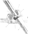
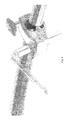
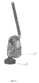
- At least one embodiment of the inventive technology may be an adjustable support apparatus 1 that comprises a ball 2 (e.g., a universal ball) having a passage 4 therethrough, where, when the apparatus is in a rack member release configuration, the ball may be slidably moved, through space, along a longitudinal axis of an item support rack member 82 established through the passage.
- the apparatus may include a housing 5 that itself includes ball compression surfaces 6 adapted to apply a ball retention force to the ball; and item support arm compression surfaces 8 adapted to apply an item support arm retention force to an item support arm 81 (either directly or indirectly).
- the adjustable support apparatus may further comprise a ball retention force enhancer 7 adapted to enhance the ball retention force (and, in pierced ball embodiments, thereby enhance the force of the ball on the item support rack member that may be established through it), perhaps without enhancing the item support arm retention force (as such, the ball retention force enhancer may be termed independently operating); and an item support arm retention force enhancer 10 adapted to enhance the item support arm retention force, perhaps without enhancing the ball retention force (as such, the item support arm retention force enhancer may be termed independently operating).
- Figs. 1-13 , 24 and 25 show "pierced ball" embodiments.
- the housing may be movable through space during axial motion of the ball relative to the item support rack member when the apparatus is simultaneously in a rack member release configuration and an item support arm lock configuration.
- the item support arm may be movable relative to the housing.
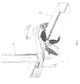
- the ball retention force enhancer applies the ball retention force in a direction that is orthogonal to that direction in which the item support arm retention force enhancer applies the item support arm retention force (see, e.g., Fig. 4 ).
- the ball is adapted to snap onto the item support rack member upon application of a threshold force (indeed, in certain embodiments, it may click).
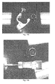
- the ball is openable along a ball hinge 61 so as to allow establishment of the ball onto the item support rack member without requiring it be slid over an end of the item support rack member (i.e., such that the ball is "side-assemblable"). Inner surfaces of the ball may conform to outer surfaces of the item support rack member.
- the item support arm may be extendable along an item support arm longitudinal axis when the apparatus is in an item support arm release configuration.
- the item support arm may be rotatable about an item support arm axis when the apparatus is in the item support arm release configuration.
- the ball retention force enhancer is the same as the item support arm retention force enhancer (see, e.g., Fig. 9 ). In preferred embodiments, the two are distinct and different parts.
- Certain embodiments of the "pierced ball” technology may include a bias clip 11 (e.g., a "broken” metal ring) adapted to keep the ball on the item support rack member when the housing is removed from the item support rack member.
- the bias clip may be established substantially around the ball.
- the ball is separable from the rack member and the housing (perhaps due to a pivot hinge 84 on one side of the ball and a ball opening joint 62 on the other).
- the housing's ball compression surfaces may be circular in shape, in at least one embodiment manifesting as four discrete circular ridges (see, e.g., Fig. 7 ); such ridges may, in certain embodiments, have a substantially 120 degree tooth angle.
- the ball may include teeth 60 and corresponding recesses at a ball opening joint (e.g., that may be opposite a ball hinge). Such may aid in retention, or even locking (and perhaps a threshold “clicking"), of the ball around the item support rack member.
- the ball retention force enhancer at least in part, may be pivotally established relative to the housing; it may include a shaft 15 and a bias element 16 established about the shaft so as to facilitate a threshold snapping of the shaft into a position from which the ball retention force can be enhanced.
- the clamp apparatus may include a ball that is movable through space by sliding along a longitudinal member around which it is established while a separate allowable motion (e.g., movement of a housing relative to an item support arm) is disallowed.
- certain embodiments of the inventive technology may be used in four distinct operational modalities, including: (1) allowed motion of the apparatus relative to an item support rack member and allowed motion relative to an item support arm; (2) allowed motion of the apparatus relative to an item support rack member but disallowed motion relative to an item support arm; (3) disallowed motion of the apparatus relative to an item support rack member but allowed motion relative to an item support arm; and (4) disallowed motion of the apparatus relative to an item support rack member and disallowed motion relative to an item support arm (retention or lock configuration).
- these four modalities may alternatively be expressed in terms of four apparatus configurations: item support arm release/lock configuration, and rack member release/lock configuration.
- the apparatus whenever the apparatus allows its motion relative to an item support rack member, the apparatus may be the to be in rack member release configuration, regardless of whether motion relative to the item support arm is allowed; similarly, whenever the apparatus allows its motion relative to an item support arm, the apparatus is in item support arm release configuration, regardless of whether motion relative to a rack member is allowed.
- Analogous descriptions apply to rack member lock configuration and item support arm lock configuration.
- rotational movement e.g., omnirotational movement
- the apparatus when the apparatus allows rotational movement of the housing relative to the ball, the apparatus is in a rack member release configuration.
- an adjustable support apparatus may comprise: a ball 20, a housing established at least partially about the ball and that itself includes: ball compression surfaces 21 adapted to apply a ball retention force to the ball; and item support rack member compression surfaces 22 adapted to apply an item support rack member retention force to an item support rack member 82.
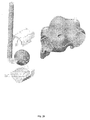
- the "solid ball” embodiments may further include a single retention force enhancer 24 adapted to enhance the item support rack member retention force and the ball retention force, wherein the ball is not configured for establishment directly onto the item support rack member (and as such is referred to as a "solid ball” embodiment, not a "pierced ball” apparatus).
- the single retention force enhancer may be pivotally established relative to the housing.
- the single retention force enhancer 24 may be adapted to simultaneously enhance the item support rack member retention force and the ball retention force.
- a portion of the item support rack member is established within the housing and has a item support rack member portion center 70, and the ball has a ball center 71, and a line between the item support rack member portion center and the ball center defines an axis 72, and wherein the single retention force enhancer applies a force in a direction 73 that is parallel the axis.
- the adjustable support apparatus may be side-assemblable.
- solid ball aspects of the inventive technology (where the ball is not configured for establishment directly onto the item support rack member), a ball does in fact exist as part of the inventive apparatus, but it does not feature a passageway therethrough for establishment of the ball on a rack member (indeed, in preferred embodiments of this aspect of the inventive technology, the ball is not configured for establishment on the rack member); as such, the ball cannot be slid along the rack member when the apparatus is in rack member release configuration as one could see in a "pierced ball” embodiment (perhaps, in a "solid ball” embodiment, a part other than the ball is being so slid).
- solid ball means nothing more than that.
- An aspect of the inventive technology may relate to features that facilitate apparatus assembly onto a rack member - more specifically, by allowing "side-assembly".
- Particular "pierced ball” embodiments may be described as an adjustable support apparatus that comprises: a ball having a passage therethrough, wherein, when the apparatus is in a rack member release configuration, the ball may be slidably moved, through space, along a longitudinal axis of an item support rack member established through the passage; a housing that itself includes ball compression surfaces adapted to apply a ball retention force to the ball; item support arm compression surfaces adapted to apply an item support arm retention force to an item support arm; a ball retention force enhancer adapted to enhance the ball retention force without enhancing the item support arm retention force; and an item support arm retention force enhancer adapted to enhance the item support arm retention force without enhancing the ball retention force, wherein the ball is adapted to be side-assemblable onto the item support rack member.
- the item support arm retention force enhancer may enhance item support arm retention force without enhancing the ball retention force, and/or the ball retention force enhancer enhances the ball retention force without enhancing the item support arm retention force.
- the housing may even be said to be side-assemblable onto the ball. It is noted that what might allow for side-assembly is, simply a hinge joint on one side of the side-assemblable part and, on the other, perhaps an openable joint. Also, the ball retention force enhancer may be pivotally established relative to the housing.
- an adjustable support apparatus may comprise a ball 20, a housing established at least partially about the ball and that itself includes: ball compression surfaces 21 adapted to apply a ball retention force to the ball; and item support rack member compression surfaces 22 adapted to apply an item support rack member retention force to an item support rack member, and at least one retention force enhancer adapted to enhance an item support rack member retention force and an item support rack member retention force; wherein the housing is adapted to be side-assemblable onto the item support rack member and possibly onto the ball.
- the at least one retention force enhancer may be a single retention force enhancer, and the single retention force enhancer may be pivotally established relative to the housing.
- an adjustable support apparatus may comprise: a ball 20, a housing established at least partially about the ball and that itself includes: ball compression surfaces 21 adapted to apply a ball retention force to the ball; and item support rack member compression surfaces 22 adapted to apply an item support rack member retention force to an item support rack member; an item support rack member force enhancer 24 adapted to enhance an item support rack member retention force; and an item support rack member retention force enhancer that is different from the ball retention force enhancer and that is adapted to apply a retention force primarily to the item support rack member; where the ball is not configured for establishment directly onto the item support rack member.
- the housing may be adapted to be side-assemblable onto the item support rack member (and possibly also onto the ball), and the ball retention force enhancer may be pivotally established relative to the housing.
- the housing may comprise the item support arm compression surfaces; the item support arm compression surfaces may be part of a separate module that is securable to and positionally adjustable relative to the housing (see Figs.
- the item support arm may be extendable along an item support arm axis during item support arm release configuration, the item support arm may be rotatable about an item support arm axis during item support arm release configuration, the ball retention force enhancer (or, in certain embodiments, the single force enhancer) may pivotally established relative to the housing;
- the ball retention force enhancer (or, in certain embodiments, the single retention force enhancer) may comprise a shaft and a bias element established about the shaft so as to facilitate a threshold snapping of the shaft into a position from which the item support rack member retention force can be enhanced;
- the ball retention force enhancer (or, in certain embodiments, the single retention force enhancer) may include threadedly engageable surfaces;
- the item support arm retention force enhancer or, in certain embodiments, the single retention force enhancer
- the housing may comprise a spatial shaft into which at least part of the ball retention force enhancer (or, in certain embodiments, the single retention force enhancer) may settle;
- the spatial shaft may comprise at least
- ball - whether used in reference to the ball that is found in “pierced ball” or “solid ball” embodiments - is broad. As such, a ball need not be perfectly spherical, nor perfectly smooth, nor be rollable in all directions. Indeed, in “pierced ball” embodiments, the passageway established through the ball renders the ball flat on two opposing sides (due to dome shaped slices of the ball that have been removed); nonetheless, such specific device is still considered a ball. It is also of note that were an apparatus is said to be side-assemblable (without further specificity), such indicates merely that is may be side-assemblable onto a item support rack member.
- any of the of the retention force enhancers may include a shaft that may be pivotally established. Ridge(s) 50 may be established as part of the spatial shaft into which the retention force enhancer (e.g., a bolt) may settle; such ridge(s) may be established so as to enable a threshold snapping of the retention force enhancer into a position from which a retention force can be enhanced.
- a bias element 16 e.g., a coiled spring
- a variety of uses and applications is contemplated for the inventive technology.
- Primary among them is the use of the apparatus in a musical instrument rack such as a drum rack, a structure designed to secure percussion instruments in that spatial orientation suitable and/or desired by a percussionist. Indeed, several of the apparatus may find use in a single drum rack to hold various drums and cymbals in their respective positions as desired.
- the basic concepts of the present invention may be embodied in a variety of ways. It involves both support techniques as well as devices to accomplish the appropriate support.
- the support techniques are disclosed as part of the results shown to be achieved by the various devices described and as steps which are inherent to utilization. They are simply the natural result of utilizing the devices as intended and described.
- some devices are disclosed, it should be understood that these not only accomplish certain methods but also can be varied in a number of ways. Importantly, as to all of the foregoing, all of these facets should be understood to be encompassed by this disclosure.
- each of the various elements of the invention and claims may also be achieved in a variety of manners.
- an element is to be understood as encompassing individual as well as plural structures that may or may not be physically connected.
- This disclosure should be understood to encompass each such variation, be it a variation of an embodiment of any apparatus embodiment, a method or process embodiment, or even merely a variation of any element of these.
- the words for each element may be expressed by equivalent apparatus terms or method terms -- even if only the function or result is the same. Such equivalent, broader, or even more generic terms should be considered to be encompassed in the description of each element or action.
- DOCUMENT NO. & KIND CODE PUB'N DATE mm-dd-yyyy PATENTEE OR APPLICANT NAME 259,957 06-20-1882 White 438,238 10-14-1890 Jefferies et al. 566,361 08-25-1896 White 3,191,484 06-29-1965 Walling 3,405,587 10-15-1968 Meazzi et al. 3,535,976 10-27-1970 Osuga 3,576,149 04-27-1971 Slingerland, Jr. 3,704,645 12-05-1972 Grauso et al.
Landscapes
- Engineering & Computer Science (AREA)
- General Engineering & Computer Science (AREA)
- Mechanical Engineering (AREA)
- Auxiliary Devices For Music (AREA)
- Pivots And Pivotal Connections (AREA)
Claims (20)
- Appareil de support réglable approprié à une utilisation avec un élément de support d'article (82) et avec un bras de support d'article (81), comprenant :- une rotule (2) qui est traversée par un passage (4) ;dans lequel, en service, lorsque ledit appareil se trouve dans une configuration de libération de l'élément de support, ladite rotule (2) est mobile de manière coulissante, à travers l'espace, le long d'un axe longitudinal d'un élément de support d'article (82), établi à travers ledit passage (4) ;- un logement (5) qui comprend lui-même des surfaces de compression de rotule (6) adaptées de façon à appliquer une force de rétention de rotule à ladite rotule (2) ;- des surfaces de compression de bras de support d'article (8) qui sont adaptées, en service, de façon à appliquer une force de rétention de bras de support d'article à un bras de support d'article (81) ;- un dispositif d'amplification de force de rétention de rotule (7) qui est adapté, en service, de façon à amplifier ladite force de rétention de rotule sans amplifier ladite force de rétention de bras de support d'article ; et- un dispositif d'amplification de force de rétention de bras de support d'article (10) adapté de façon à amplifier ladite force de rétention de bras de support d'article sans amplifier ladite force de rétention de rotule ;dans lequel, en service, ledit logement (5) est mobile à travers l'espace au cours dudit mouvement axial longitudinal de ladite rotule par rapport audit élément de support d'article (82) lorsque ledit appareil se trouve simultanément dans :- ladite configuration de libération de l'élément de support (82) ; et- une configuration de verrouillage de bras de support d'article (81) ;dans lequel ledit logement (5) est adapté de façon à pouvoir être assemblé à côté sur l'élément de support d'article (82) et sur la rotule (2), caractérisé en ce que :en service, ladite rotule (2) peut être ouverte le long d'une charnière de rotule de façon à permettre la mise en place de la rotule sur l'élément de support d'article (82) sans avoir à la glisser sur une extrémité de l'élément de support d'article (82).
- Appareil de support réglable selon la revendication 1, dans lequel ledit logement (5) comprend lesdites surfaces de compression de bras de support d'article (8).
- Appareil de support réglable selon la revendication 1, dans lequel lesdites surfaces de compression de bras de support d'article (8) font partie d'un module distinct qui peut être fixé sur ledit logement (5) et réglé en position par rapport à celui-ci.
- Appareil de support réglable selon la revendication 1, dans lequel ledit bras de support d'article (81) peut se déployer le long d'un axe de bras de support d'article au cours de ladite configuration de libération de support d'article.
- Appareil de support réglable selon la revendication 1, dans lequel ledit bras de support d'article (81) peut tourner autour d'un axe de bras de support d'article au cours de ladite configuration de libération de support d'article.
- Appareil de support réglable selon la revendication 1, dans lequel ledit dispositif d'amplification de force de rétention de rotule (7) est mis en place de manière pivotante par rapport audit logement (5).
- Appareil de support réglable selon la revendication 1, dans lequel ledit dispositif d'amplification de force de rétention de rotule (7) comprend un arbre et un élément de sollicitation mis en place autour de l'arbre de façon à faciliter un encliquetage à seuil de l'arbre dans une position à partir de laquelle la force de rétention de l'élément de support d'article peut être amplifiée.
- Appareil de support réglable selon la revendication 1, dans lequel ledit logement (5) comprend un arbre spatial dans lequel peut se situer une partie au moins dudit dispositif d'amplification de force de rétention de rotule (7).
- Appareil de support réglable selon la revendication 8, dans lequel ledit arbre spatial comprend une saillie (50) au moins configurée de façon à permettre un encliquetage à seuil du dispositif d'amplification de force de rétention de rotule (7) dans une position à partir de laquelle une force de rétention de rotule peut être amplifiée.
- Appareil de support réglable selon la revendication 1, comprenant en outre un élément de sollicitation (16) mis en place de façon à faciliter le fonctionnement du dispositif d'amplification de force de rétention de rotule (7).
- Appareil de support réglable selon la revendication 1, dans lequel ladite rotule (2) est adaptée de façon à s'encliqueter sur l'élément de support d'article (82) lors de l'application d'une force de seuil.
- Appareil de support réglable selon la revendication 1, dans lequel lesdites surfaces intérieures de ladite rotule se conforment aux surfaces extérieures dudit élément de support d'article (82).
- Appareil de support réglable selon la revendication 1, comprenant en outre une attache de sollicitation (11) adaptée de façon à maintenir la rotule (2) sur l'élément de support d'article (82) lorsque le logement (5) est retiré de l'élément de support d'article.
- Appareil de support réglable selon la revendication 1, dans lequel ladite rotule (2) peut être séparée de l'élément de support et du logement (5).
- Appareil de support réglable selon la revendication 1, dans lequel ledit dispositif d'amplification de force de rétention de rotule (7) et ledit dispositif d'amplification de force de rétention de bras de support d'article (10) sont des pièces distinctes et différentes.
- Appareil de support réglable selon la revendication 1, dans lequel ledit appareil de support réglable (1) est un appareil de support d'instrument à percussion.
- Appareil de support réglable selon la revendication 1, dans lequel ledit appareil permet un déplacement en rotation du logement (5) par rapport à la rotule (2) tout en interdisant simultanément un mouvement du logement par rapport à l'élément de support.
- Appareil de support réglable selon la revendication 1, dans lequel ledit dispositif d'amplification de force de rétention de rotule (7) applique ladite force de rétention de rotule dans une direction qui est orthogonale par rapport à la direction dans laquelle ledit dispositif d'amplification de force de rétention de bras de support d'article (10) applique ladite force de rétention de bras de support d'article.
- Appareil de support réglable selon la revendication 1, dans lequel ladite rotule (2) est adaptée de façon à pouvoir être assemblée à côté sur ledit élément de support d'article (82).
- Appareil de support réglable selon la revendication 1, dans lequel ledit élément de support d'article (82) est un élément de support de tambour.
Applications Claiming Priority (2)
| Application Number | Priority Date | Filing Date | Title |
|---|---|---|---|
| US92644807P | 2007-04-27 | 2007-04-27 | |
| PCT/US2008/061807 WO2008134653A1 (fr) | 2007-04-27 | 2008-04-28 | Appareil de support d'instrument à percussion |
Publications (3)
| Publication Number | Publication Date |
|---|---|
| EP2152125A1 EP2152125A1 (fr) | 2010-02-17 |
| EP2152125A4 EP2152125A4 (fr) | 2011-09-21 |
| EP2152125B1 true EP2152125B1 (fr) | 2014-12-10 |
Family
ID=39926115
Family Applications (1)
| Application Number | Title | Priority Date | Filing Date |
|---|---|---|---|
| EP08747048.0A Not-in-force EP2152125B1 (fr) | 2007-04-27 | 2008-04-28 | Appareil de support d'instrument a percussion |
Country Status (4)
| Country | Link |
|---|---|
| US (1) | US8106278B2 (fr) |
| EP (1) | EP2152125B1 (fr) |
| JP (1) | JP2010525418A (fr) |
| WO (1) | WO2008134653A1 (fr) |
Families Citing this family (31)
| Publication number | Priority date | Publication date | Assignee | Title |
|---|---|---|---|---|
| EP2152125B1 (fr) * | 2007-04-27 | 2014-12-10 | Swift Distribution, Inc. | Appareil de support d'instrument a percussion |
| WO2009091929A2 (fr) | 2008-01-15 | 2009-07-23 | Swift Distribution, Inc, | Appareil de support musical |
| JP5441507B2 (ja) * | 2009-06-11 | 2014-03-12 | ローランド株式会社 | ドラム用ブラケット |
| JP5528742B2 (ja) * | 2009-08-31 | 2014-06-25 | ローランド株式会社 | パイプホルダー |
| JP5480566B2 (ja) * | 2009-08-31 | 2014-04-23 | ローランド株式会社 | 楽器スタンド用のクランプ |
| USD667819S1 (en) | 2010-01-13 | 2012-09-25 | Swift Distribution, Inc. | Support stand |
| USD687421S1 (en) | 2010-01-13 | 2013-08-06 | Swift Distribution, Inc. | Microphone stand |
| USD652190S1 (en) | 2010-01-13 | 2012-01-10 | Swift Distribution, Inc. | Cart |
| JP5192028B2 (ja) * | 2010-11-16 | 2013-05-08 | 星野楽器株式会社 | タムホルダ |
| US9087498B2 (en) | 2010-11-16 | 2015-07-21 | Hoshino Gakki Co., Ltd. | Tom holder |
| CN102339600A (zh) * | 2011-07-27 | 2012-02-01 | 天津市津宝乐器有限公司 | 压板式大鼓顶支架 |
| JP5485235B2 (ja) * | 2011-08-17 | 2014-05-07 | 星野楽器株式会社 | 楽器用スタンド |
| US8667648B2 (en) * | 2011-08-26 | 2014-03-11 | Mtd Products Inc | Ball handle assembly for a handheld tool |
| USD731299S1 (en) * | 2012-01-17 | 2015-06-09 | Yamaha Corporation | Clamp of a stand for supporting an object |
| USD711731S1 (en) * | 2012-01-17 | 2014-08-26 | Yamaha Corporation | Clamp of a stand for supporting an instrument |
| USD665238S1 (en) | 2012-03-22 | 2012-08-14 | Karsten Manufacturing Corporation | Wrench tool for sports equipment |
| USD668921S1 (en) | 2012-03-22 | 2012-10-16 | Karsten Manufacturing Corporation | Wrench tool for sports equipment |
| USD711730S1 (en) * | 2012-03-26 | 2014-08-26 | Kevin McKiernan | Tube clamp |
| USD689502S1 (en) | 2013-01-18 | 2013-09-10 | Swift Distribution, Inc. | Device support apparatus |
| USD749344S1 (en) | 2013-01-22 | 2016-02-16 | Swift Distribution, LLC | Support yoke |
| USD748937S1 (en) | 2013-01-22 | 2016-02-09 | Swift Distribution, LLC | Support apparatus |
| CN103353049B (zh) * | 2013-07-08 | 2016-08-24 | 中国电子科技集团公司第四十五研究所 | 超声扫描探头的夹紧结构及应用其的探头夹紧方法 |
| US9572741B2 (en) * | 2013-08-28 | 2017-02-21 | Tidi Cfi Products, Llc | Surgical table arm support assembly and surgical table |
| US10030694B2 (en) * | 2013-12-17 | 2018-07-24 | Ingersoll-Rand Company | Adjustable joints |
| US9604703B2 (en) * | 2014-07-02 | 2017-03-28 | Hobie Cat Company | Rail mounting system |
| CN104132056A (zh) * | 2014-07-28 | 2014-11-05 | 朱德仲 | 一种工业用多向连接轴 |
| CN204387626U (zh) * | 2014-12-25 | 2015-06-10 | 佛山市南海祥旺光学电子制品有限公司 | 三脚架的中管反转装置 |
| US10881362B2 (en) * | 2018-11-20 | 2021-01-05 | General Electric Company | Systems for laser alignment |
| USD986047S1 (en) * | 2020-12-22 | 2023-05-16 | White Mule Company | J-clamp assembly for truck saddle-mounts |
| USD1060575S1 (en) * | 2023-07-12 | 2025-02-04 | Bellicon Ag | Fixing device |
| USD1043461S1 (en) | 2023-07-27 | 2024-09-24 | White Mule Company | J-clamp assembly for truck saddle mounts |
Citations (1)
| Publication number | Priority date | Publication date | Assignee | Title |
|---|---|---|---|---|
| US20040135040A1 (en) * | 2003-01-15 | 2004-07-15 | Ultimate Support Systems, Inc. | Microphone support boom movement control apparatus and method with differential motion isolation capability |
Family Cites Families (85)
| Publication number | Priority date | Publication date | Assignee | Title |
|---|---|---|---|---|
| US566361A (en) * | 1896-08-25 | Shade-holder for baby-carriages | ||
| US169383A (en) * | 1875-11-02 | Improvement in ball-and-socket joints | ||
| US259957A (en) * | 1882-06-20 | Ball-and-socket joint | ||
| US438238A (en) * | 1890-10-14 | Top-support for children s carriages | ||
| US958052A (en) * | 1909-07-28 | 1910-05-17 | David Williams | Pipe support and clamp. |
| US1574899A (en) * | 1924-06-07 | 1926-03-02 | Albert T Kellogg | Glareshield |
| US1672605A (en) * | 1924-07-17 | 1928-06-05 | Imp Brass Mfg Co | Mounting for windshield spotlights, etc. |
| US2196338A (en) * | 1937-10-04 | 1940-04-09 | Trailwagons Inc | Trailer frame |
| US2433594A (en) | 1946-08-22 | 1947-12-30 | Calo Carlo | Drum stand |
| US2767003A (en) * | 1948-06-22 | 1956-10-16 | Emil Greiner Company | Joint for universally adjustable frame |
| US2652221A (en) * | 1951-05-03 | 1953-09-15 | Kampa Company Inc | Rearview mirror mounting |
| US2754616A (en) * | 1953-01-30 | 1956-07-17 | William H Law | Fishing bob |
| US3191484A (en) * | 1963-06-24 | 1965-06-29 | Albert S Walling | Drum support |
| US3405587A (en) * | 1967-05-15 | 1968-10-15 | Meazzi Remo | Supports, particularly for drums and the like, with arrangements admitting the swing motion of the instrument over a wide angulation range and its quick locking and release, and related improved supports |
| US3535976A (en) | 1968-04-01 | 1970-10-27 | Pearl Musical Instr Mfg Co Ltd | Tom-tom holder |
| US3576149A (en) | 1969-04-03 | 1971-04-27 | Slingerland Durm Co | Drum holder |
| US3704645A (en) * | 1971-09-01 | 1972-12-05 | C F Martin & Co | Accessory holder for musical instruments of the percussion type |
| US3843083A (en) * | 1972-11-09 | 1974-10-22 | Wonder Piles | Mounting apparatus for portable device |
| FR2436932A1 (fr) * | 1978-09-19 | 1980-04-18 | Wonder | Panoplie d'accessoires de camping |
| US3989321A (en) | 1974-11-25 | 1976-11-02 | Heim Universal Corporation | Spherical bearing assembly with spring biased segmented inner race member |
| JPS567999Y2 (fr) | 1976-08-12 | 1981-02-21 | ||
| JPS563756Y2 (fr) | 1977-01-25 | 1981-01-27 | ||
| US4357651A (en) * | 1980-12-23 | 1982-11-02 | Stewart-Warner Corporation | Rectangular seal beam lamp and universal support assembly |
| JPS591094U (ja) | 1982-06-25 | 1984-01-06 | 星野楽器株式会社 | トムホルダ |
| JPH0524955Y2 (fr) | 1986-07-31 | 1993-06-24 | ||
| US5515246A (en) * | 1988-12-16 | 1996-05-07 | Mag Instrument, Inc. | Holder clamp assembly |
| US5109321A (en) * | 1988-12-16 | 1992-04-28 | Mag Instrument, Inc. | Flashlight holder clamp assembly |
| US4958793A (en) * | 1989-05-01 | 1990-09-25 | Hess Norman B | Stanchion |
| US4971271A (en) * | 1989-05-05 | 1990-11-20 | Sularz Frank D | Article organizer and holder assembly |
| US4946122A (en) * | 1989-09-29 | 1990-08-07 | The United States Of America As Represented By The Administrator Of The National Aeronautics And Space Administration | Post clamp |
| CA2016360C (fr) * | 1990-05-09 | 1993-11-09 | Richard John Jones | Pare-boue de bicyclettes |
| CH684928A5 (fr) * | 1990-12-10 | 1995-02-15 | Jaquet Orthopedie | Fixateur externe. |
| DE4333913C2 (de) * | 1992-10-09 | 1997-11-20 | Link Johs Sonor Gmbh | Einstellvorrichtung an längen- und/oder neigungsverstellbaren Haltern, insbesondere für Percussions-Musikinstrumente |
| US5860728A (en) * | 1993-02-08 | 1999-01-19 | Mag Instrument, Inc. | Holder clamp assembly |
| US5501544A (en) * | 1994-11-10 | 1996-03-26 | Nolu Plastics, Inc. | Three-piece clamping assembly |
| US5498098A (en) * | 1994-11-10 | 1996-03-12 | Nolu Plastics, Inc. | Two-piece clamping assembly |
| JP3014483U (ja) | 1995-02-08 | 1995-08-08 | 星野楽器株式会社 | ドラムの自在保持ホルダ |
| JP3093975B2 (ja) * | 1996-07-02 | 2000-10-03 | 株式会社平間理化研究所 | レジスト剥離液管理装置 |
| US6394408B1 (en) * | 1996-08-13 | 2002-05-28 | Brunswick Corporation | Trolling motor column mounting system |
| US5899627A (en) | 1996-09-12 | 1999-05-04 | Minnesota Scientific, Inc. | Clamp for retractor support |
| US5881667A (en) * | 1997-04-10 | 1999-03-16 | Herbert; Jeffrey J. | Antenna ball identification system |
| US5895874A (en) | 1997-07-14 | 1999-04-20 | Hwa Shin Musical Instrument Co. Ltd. | Wide angle tom-tom holder |
| US6054645A (en) | 1997-08-20 | 2000-04-25 | Gauger; Gary L. | Hi-hat percussion instrument |
| US5804747A (en) | 1997-11-26 | 1998-09-08 | Chen; Chang-Hui | Musical instrument holder |
| US6070835A (en) * | 1998-03-19 | 2000-06-06 | Qualcomm Incorporated | Ball-compression grommet |
| US5949009A (en) | 1998-08-03 | 1999-09-07 | Tay-E Co., Ltd. | Adjustable tom-tom holder |
| US5973248A (en) * | 1998-08-12 | 1999-10-26 | Tay E Co. Ltd. | Combination side-drum holder |
| US6676570B2 (en) * | 1998-10-19 | 2004-01-13 | Alexander Valentino | Adjustable rehabilitation exercise device |
| JP3447970B2 (ja) * | 1999-01-22 | 2003-09-16 | 星野楽器株式会社 | 楽器用クランプ装置 |
| JP3420715B2 (ja) | 1999-01-25 | 2003-06-30 | 星野楽器株式会社 | 楽器用クランプ装置 |
| US6075190A (en) | 1999-05-07 | 2000-06-13 | Remo, Inc. | Drum holder |
| US6520467B2 (en) * | 1999-06-16 | 2003-02-18 | Anne Marie Thomas | Hair dryer holder |
| US6189229B1 (en) * | 1999-06-16 | 2001-02-20 | Andrew P. Thomas | Hair dryer holder |
| GB2352475B (en) * | 1999-11-17 | 2001-11-14 | Jarzon Plastics Ltd | Nut and seat assembly for clamp |
| US6520465B1 (en) * | 1999-12-16 | 2003-02-18 | Wonderland Nurserygoods Co., Ltd. | Rotation and translation bracket |
| CA2299483A1 (fr) * | 2000-01-06 | 2001-07-06 | Dan Reinstein | Appuie-tete |
| US6513774B2 (en) | 2000-03-27 | 2003-02-04 | Michael J. Hailson | Adjustable mounting apparatus |
| US6386786B1 (en) * | 2000-04-07 | 2002-05-14 | Delaware Capital Formation, Inc. | Rotating clamp |
| ATE309102T1 (de) * | 2000-05-24 | 2005-11-15 | Silverbrook Res Pty Ltd | Sensor für die papierdicke in einem printer |
| US6346665B1 (en) * | 2000-10-05 | 2002-02-12 | Tsun-Chi Liao | Dual adjusting holder for drum |
| EP1334463B1 (fr) * | 2000-11-06 | 2010-03-31 | Koninklijke Philips Electronics N.V. | Procede de mesure du mouvement d'un dispositif de saisie |
| US6610916B1 (en) * | 2001-12-24 | 2003-08-26 | Michael Torrez | Drummer's snake |
| US6653540B2 (en) * | 2002-01-28 | 2003-11-25 | First Act, Inc. | Mechanism for supporting musical instruments |
| JP4002787B2 (ja) * | 2002-05-29 | 2007-11-07 | 矢崎総業株式会社 | ハーネス固定具 |
| JP4279248B2 (ja) * | 2002-06-04 | 2009-06-17 | コーニンクレッカ フィリップス エレクトロニクス エヌ ヴィ | 入力デバイスの移動を測定する方法 |
| JP3878905B2 (ja) * | 2002-11-20 | 2007-02-07 | 株式会社オーディオテクニカ | マイクロホン支持具 |
| US6988696B2 (en) * | 2003-06-03 | 2006-01-24 | Delaware Capital Formation, Inc. | Mounting member with snap in swivel member |
| US7052125B2 (en) * | 2003-08-28 | 2006-05-30 | Lexmark International, Inc. | Apparatus and method for ink-jet printing onto an intermediate drum in a helical pattern |
| US7055910B2 (en) | 2003-09-04 | 2006-06-06 | Medical Device Group, Inc. | Phlebotomy armrest assembly and method of using same |
| KR100975571B1 (ko) * | 2004-05-28 | 2010-08-13 | 삼성전자주식회사 | 배관 고정 장치 |
| US7954737B2 (en) * | 2007-10-04 | 2011-06-07 | Fellowes, Inc. | Shredder thickness with anti-jitter feature |
| US7631822B2 (en) * | 2004-09-10 | 2009-12-15 | Fellowes Inc. | Shredder with thickness detector |
| US7668458B2 (en) * | 2005-03-02 | 2010-02-23 | Thomas D Knightlinger | Protection device for photographic apparatus |
| US8672247B2 (en) * | 2005-07-11 | 2014-03-18 | Fellowes, Inc. | Shredder with thickness detector |
| WO2008008464A2 (fr) * | 2006-07-14 | 2008-01-17 | Landscape Structures, Inc. | système de jeu basé sur une arche |
| US7637686B2 (en) * | 2007-03-02 | 2009-12-29 | The Boeing Company | Swivel fitting attachment apparatus |
| USD576870S1 (en) * | 2007-04-27 | 2008-09-16 | Yamaha Corporation | Drum rack member clamp |
| USD613092S1 (en) * | 2007-04-27 | 2010-04-06 | Swift Distribution, Inc. | Drum rack |
| USD580262S1 (en) * | 2007-04-27 | 2008-11-11 | Yamaha Corporation | Percussion instrument support arm clamp |
| EP2152125B1 (fr) * | 2007-04-27 | 2014-12-10 | Swift Distribution, Inc. | Appareil de support d'instrument a percussion |
| US7805881B2 (en) * | 2007-05-14 | 2010-10-05 | Patrick John Kavanaugh | Bead attachment |
| US7534965B1 (en) * | 2008-01-29 | 2009-05-19 | Thompson David M | Cable grommet with ball and socket |
| US8747418B2 (en) * | 2008-08-15 | 2014-06-10 | Monteris Medical Corporation | Trajectory guide |
| DE102009024909B4 (de) * | 2009-06-15 | 2012-08-30 | Gewa Music Gmbh | Snareständer mit selbstjustierender Korbgröße |
| JP5014462B2 (ja) * | 2010-05-11 | 2012-08-29 | キヤノン株式会社 | プリント装置およびシート処理装置 |
-
2008
- 2008-04-28 EP EP08747048.0A patent/EP2152125B1/fr not_active Not-in-force
- 2008-04-28 WO PCT/US2008/061807 patent/WO2008134653A1/fr not_active Ceased
- 2008-04-28 JP JP2010506562A patent/JP2010525418A/ja not_active Withdrawn
- 2008-04-28 US US12/597,905 patent/US8106278B2/en active Active
Patent Citations (1)
| Publication number | Priority date | Publication date | Assignee | Title |
|---|---|---|---|---|
| US20040135040A1 (en) * | 2003-01-15 | 2004-07-15 | Ultimate Support Systems, Inc. | Microphone support boom movement control apparatus and method with differential motion isolation capability |
Also Published As
| Publication number | Publication date |
|---|---|
| EP2152125A4 (fr) | 2011-09-21 |
| US8106278B2 (en) | 2012-01-31 |
| US20100116121A1 (en) | 2010-05-13 |
| WO2008134653A1 (fr) | 2008-11-06 |
| JP2010525418A (ja) | 2010-07-22 |
| EP2152125A1 (fr) | 2010-02-17 |
Similar Documents
| Publication | Publication Date | Title |
|---|---|---|
| US20100116121A1 (en) | Percussion Instrument Support Apparatus | |
| CN106662136B (zh) | 用于紧固彼此靠置的部件的销钉 | |
| US8372120B2 (en) | Multi-axial cross connector | |
| US9208761B2 (en) | Musical instrument tilter and cymbal stand | |
| US10875467B2 (en) | Holder for flat, approximately rectangular devices such as tablet computers or smartphones | |
| WO2015012075A1 (fr) | Accessoire de capteur | |
| EP1443800A3 (fr) | Casque d'écoute | |
| US20150069193A1 (en) | Arrangement for Mounting and Adjusting a Sensor | |
| EP1898191A3 (fr) | Dispositif de détection de charge | |
| US20070209487A1 (en) | Torque fastening devices and apparatuses | |
| JP2002192478A (ja) | 圧締具 | |
| EP3425219A1 (fr) | Unité de joint à rotule pouvant se déplacer le long de rainures de guidage | |
| US8651443B2 (en) | Device for the clamping attachment of a scale | |
| JP2015530530A (ja) | リングナット | |
| FR2886605A1 (fr) | Module de blocage d'une colonne de direction et colonne de direction correspondante | |
| US12297956B2 (en) | Joint for a support arm and support arm including the joint | |
| US7005568B2 (en) | Extension connector for an angle adjustable cymbal stand | |
| WO2005096782A3 (fr) | Procedes et systemes pour munir des applications d'une fonctionnalite de recherche internet | |
| US8292246B2 (en) | Apparatus for an inclinable support of a speaker | |
| US20060071188A1 (en) | Flow restrictor | |
| JP2008530573A5 (fr) | ||
| US7267606B2 (en) | Angle retaining assembly of a hand tool | |
| GB2452046A (en) | Sprung socket clamp for round objects | |
| US20070194190A1 (en) | Device to be fastened to a support which is provided with a threaded bolt | |
| JP2022533680A (ja) | 車両用操作ユニット |
Legal Events
| Date | Code | Title | Description |
|---|---|---|---|
| PUAI | Public reference made under article 153(3) epc to a published international application that has entered the european phase |
Free format text: ORIGINAL CODE: 0009012 |
|
| 17P | Request for examination filed |
Effective date: 20091127 |
|
| AK | Designated contracting states |
Kind code of ref document: A1 Designated state(s): AT BE BG CH CY CZ DE DK EE ES FI FR GB GR HR HU IE IS IT LI LT LU LV MC MT NL NO PL PT RO SE SI SK TR |
|
| AX | Request for extension of the european patent |
Extension state: AL BA MK RS |
|
| DAX | Request for extension of the european patent (deleted) | ||
| A4 | Supplementary search report drawn up and despatched |
Effective date: 20110819 |
|
| RIC1 | Information provided on ipc code assigned before grant |
Ipc: A47F 5/14 20060101AFI20110815BHEP Ipc: F16M 11/14 20060101ALI20110815BHEP |
|
| 17Q | First examination report despatched |
Effective date: 20130206 |
|
| GRAP | Despatch of communication of intention to grant a patent |
Free format text: ORIGINAL CODE: EPIDOSNIGR1 |
|
| INTG | Intention to grant announced |
Effective date: 20141001 |
|
| GRAS | Grant fee paid |
Free format text: ORIGINAL CODE: EPIDOSNIGR3 |
|
| GRAA | (expected) grant |
Free format text: ORIGINAL CODE: 0009210 |
|
| AK | Designated contracting states |
Kind code of ref document: B1 Designated state(s): AT BE BG CH CY CZ DE DK EE ES FI FR GB GR HR HU IE IS IT LI LT LU LV MC MT NL NO PL PT RO SE SI SK TR |
|
| REG | Reference to a national code |
Ref country code: GB Ref legal event code: FG4D |
|
| REG | Reference to a national code |
Ref country code: CH Ref legal event code: EP |
|
| REG | Reference to a national code |
Ref country code: IE Ref legal event code: FG4D |
|
| REG | Reference to a national code |
Ref country code: AT Ref legal event code: REF Ref document number: 700230 Country of ref document: AT Kind code of ref document: T Effective date: 20150115 |
|
| REG | Reference to a national code |
Ref country code: DE Ref legal event code: R096 Ref document number: 602008035790 Country of ref document: DE Effective date: 20150122 |
|
| REG | Reference to a national code |
Ref country code: AT Ref legal event code: MK05 Ref document number: 700230 Country of ref document: AT Kind code of ref document: T Effective date: 20141210 Ref country code: NL Ref legal event code: VDEP Effective date: 20141210 |
|
| REG | Reference to a national code |
Ref country code: NL Ref legal event code: VDEP Effective date: 20141210 |
|
| PG25 | Lapsed in a contracting state [announced via postgrant information from national office to epo] |
Ref country code: FI Free format text: LAPSE BECAUSE OF FAILURE TO SUBMIT A TRANSLATION OF THE DESCRIPTION OR TO PAY THE FEE WITHIN THE PRESCRIBED TIME-LIMIT Effective date: 20141210 Ref country code: NO Free format text: LAPSE BECAUSE OF FAILURE TO SUBMIT A TRANSLATION OF THE DESCRIPTION OR TO PAY THE FEE WITHIN THE PRESCRIBED TIME-LIMIT Effective date: 20150310 Ref country code: LT Free format text: LAPSE BECAUSE OF FAILURE TO SUBMIT A TRANSLATION OF THE DESCRIPTION OR TO PAY THE FEE WITHIN THE PRESCRIBED TIME-LIMIT Effective date: 20141210 Ref country code: ES Free format text: LAPSE BECAUSE OF FAILURE TO SUBMIT A TRANSLATION OF THE DESCRIPTION OR TO PAY THE FEE WITHIN THE PRESCRIBED TIME-LIMIT Effective date: 20141210 |
|
| REG | Reference to a national code |
Ref country code: LT Ref legal event code: MG4D |
|
| PG25 | Lapsed in a contracting state [announced via postgrant information from national office to epo] |
Ref country code: LV Free format text: LAPSE BECAUSE OF FAILURE TO SUBMIT A TRANSLATION OF THE DESCRIPTION OR TO PAY THE FEE WITHIN THE PRESCRIBED TIME-LIMIT Effective date: 20141210 Ref country code: GR Free format text: LAPSE BECAUSE OF FAILURE TO SUBMIT A TRANSLATION OF THE DESCRIPTION OR TO PAY THE FEE WITHIN THE PRESCRIBED TIME-LIMIT Effective date: 20150311 Ref country code: SE Free format text: LAPSE BECAUSE OF FAILURE TO SUBMIT A TRANSLATION OF THE DESCRIPTION OR TO PAY THE FEE WITHIN THE PRESCRIBED TIME-LIMIT Effective date: 20141210 Ref country code: AT Free format text: LAPSE BECAUSE OF FAILURE TO SUBMIT A TRANSLATION OF THE DESCRIPTION OR TO PAY THE FEE WITHIN THE PRESCRIBED TIME-LIMIT Effective date: 20141210 Ref country code: HR Free format text: LAPSE BECAUSE OF FAILURE TO SUBMIT A TRANSLATION OF THE DESCRIPTION OR TO PAY THE FEE WITHIN THE PRESCRIBED TIME-LIMIT Effective date: 20141210 |
|
| PG25 | Lapsed in a contracting state [announced via postgrant information from national office to epo] |
Ref country code: NL Free format text: LAPSE BECAUSE OF FAILURE TO SUBMIT A TRANSLATION OF THE DESCRIPTION OR TO PAY THE FEE WITHIN THE PRESCRIBED TIME-LIMIT Effective date: 20141210 |
|
| PG25 | Lapsed in a contracting state [announced via postgrant information from national office to epo] |
Ref country code: PT Free format text: LAPSE BECAUSE OF FAILURE TO SUBMIT A TRANSLATION OF THE DESCRIPTION OR TO PAY THE FEE WITHIN THE PRESCRIBED TIME-LIMIT Effective date: 20150410 Ref country code: SK Free format text: LAPSE BECAUSE OF FAILURE TO SUBMIT A TRANSLATION OF THE DESCRIPTION OR TO PAY THE FEE WITHIN THE PRESCRIBED TIME-LIMIT Effective date: 20141210 Ref country code: EE Free format text: LAPSE BECAUSE OF FAILURE TO SUBMIT A TRANSLATION OF THE DESCRIPTION OR TO PAY THE FEE WITHIN THE PRESCRIBED TIME-LIMIT Effective date: 20141210 Ref country code: RO Free format text: LAPSE BECAUSE OF FAILURE TO SUBMIT A TRANSLATION OF THE DESCRIPTION OR TO PAY THE FEE WITHIN THE PRESCRIBED TIME-LIMIT Effective date: 20141210 Ref country code: CZ Free format text: LAPSE BECAUSE OF FAILURE TO SUBMIT A TRANSLATION OF THE DESCRIPTION OR TO PAY THE FEE WITHIN THE PRESCRIBED TIME-LIMIT Effective date: 20141210 |
|
| PG25 | Lapsed in a contracting state [announced via postgrant information from national office to epo] |
Ref country code: IS Free format text: LAPSE BECAUSE OF FAILURE TO SUBMIT A TRANSLATION OF THE DESCRIPTION OR TO PAY THE FEE WITHIN THE PRESCRIBED TIME-LIMIT Effective date: 20150410 Ref country code: PL Free format text: LAPSE BECAUSE OF FAILURE TO SUBMIT A TRANSLATION OF THE DESCRIPTION OR TO PAY THE FEE WITHIN THE PRESCRIBED TIME-LIMIT Effective date: 20141210 |
|
| REG | Reference to a national code |
Ref country code: DE Ref legal event code: R097 Ref document number: 602008035790 Country of ref document: DE |
|
| PLBE | No opposition filed within time limit |
Free format text: ORIGINAL CODE: 0009261 |
|
| STAA | Information on the status of an ep patent application or granted ep patent |
Free format text: STATUS: NO OPPOSITION FILED WITHIN TIME LIMIT |
|
| PG25 | Lapsed in a contracting state [announced via postgrant information from national office to epo] |
Ref country code: DK Free format text: LAPSE BECAUSE OF FAILURE TO SUBMIT A TRANSLATION OF THE DESCRIPTION OR TO PAY THE FEE WITHIN THE PRESCRIBED TIME-LIMIT Effective date: 20141210 |
|
| 26N | No opposition filed |
Effective date: 20150911 |
|
| PG25 | Lapsed in a contracting state [announced via postgrant information from national office to epo] |
Ref country code: LU Free format text: LAPSE BECAUSE OF FAILURE TO SUBMIT A TRANSLATION OF THE DESCRIPTION OR TO PAY THE FEE WITHIN THE PRESCRIBED TIME-LIMIT Effective date: 20150428 Ref country code: MC Free format text: LAPSE BECAUSE OF FAILURE TO SUBMIT A TRANSLATION OF THE DESCRIPTION OR TO PAY THE FEE WITHIN THE PRESCRIBED TIME-LIMIT Effective date: 20141210 |
|
| REG | Reference to a national code |
Ref country code: CH Ref legal event code: PL |
|
| PG25 | Lapsed in a contracting state [announced via postgrant information from national office to epo] |
Ref country code: IT Free format text: LAPSE BECAUSE OF FAILURE TO SUBMIT A TRANSLATION OF THE DESCRIPTION OR TO PAY THE FEE WITHIN THE PRESCRIBED TIME-LIMIT Effective date: 20141210 |
|
| REG | Reference to a national code |
Ref country code: IE Ref legal event code: MM4A |
|
| PG25 | Lapsed in a contracting state [announced via postgrant information from national office to epo] |
Ref country code: LI Free format text: LAPSE BECAUSE OF NON-PAYMENT OF DUE FEES Effective date: 20150430 Ref country code: CH Free format text: LAPSE BECAUSE OF NON-PAYMENT OF DUE FEES Effective date: 20150430 |
|
| PG25 | Lapsed in a contracting state [announced via postgrant information from national office to epo] |
Ref country code: SI Free format text: LAPSE BECAUSE OF FAILURE TO SUBMIT A TRANSLATION OF THE DESCRIPTION OR TO PAY THE FEE WITHIN THE PRESCRIBED TIME-LIMIT Effective date: 20141210 |
|
| REG | Reference to a national code |
Ref country code: FR Ref legal event code: PLFP Year of fee payment: 9 |
|
| PG25 | Lapsed in a contracting state [announced via postgrant information from national office to epo] |
Ref country code: IE Free format text: LAPSE BECAUSE OF NON-PAYMENT OF DUE FEES Effective date: 20150428 |
|
| PG25 | Lapsed in a contracting state [announced via postgrant information from national office to epo] |
Ref country code: BE Free format text: LAPSE BECAUSE OF FAILURE TO SUBMIT A TRANSLATION OF THE DESCRIPTION OR TO PAY THE FEE WITHIN THE PRESCRIBED TIME-LIMIT Effective date: 20141210 |
|
| PG25 | Lapsed in a contracting state [announced via postgrant information from national office to epo] |
Ref country code: MT Free format text: LAPSE BECAUSE OF FAILURE TO SUBMIT A TRANSLATION OF THE DESCRIPTION OR TO PAY THE FEE WITHIN THE PRESCRIBED TIME-LIMIT Effective date: 20141210 |
|
| REG | Reference to a national code |
Ref country code: FR Ref legal event code: PLFP Year of fee payment: 10 |
|
| PG25 | Lapsed in a contracting state [announced via postgrant information from national office to epo] |
Ref country code: HU Free format text: LAPSE BECAUSE OF FAILURE TO SUBMIT A TRANSLATION OF THE DESCRIPTION OR TO PAY THE FEE WITHIN THE PRESCRIBED TIME-LIMIT; INVALID AB INITIO Effective date: 20080428 Ref country code: BG Free format text: LAPSE BECAUSE OF FAILURE TO SUBMIT A TRANSLATION OF THE DESCRIPTION OR TO PAY THE FEE WITHIN THE PRESCRIBED TIME-LIMIT Effective date: 20141210 |
|
| PG25 | Lapsed in a contracting state [announced via postgrant information from national office to epo] |
Ref country code: CY Free format text: LAPSE BECAUSE OF FAILURE TO SUBMIT A TRANSLATION OF THE DESCRIPTION OR TO PAY THE FEE WITHIN THE PRESCRIBED TIME-LIMIT Effective date: 20141210 |
|
| PG25 | Lapsed in a contracting state [announced via postgrant information from national office to epo] |
Ref country code: TR Free format text: LAPSE BECAUSE OF FAILURE TO SUBMIT A TRANSLATION OF THE DESCRIPTION OR TO PAY THE FEE WITHIN THE PRESCRIBED TIME-LIMIT Effective date: 20141210 |
|
| REG | Reference to a national code |
Ref country code: FR Ref legal event code: PLFP Year of fee payment: 11 |
|
| PGFP | Annual fee paid to national office [announced via postgrant information from national office to epo] |
Ref country code: GB Payment date: 20180329 Year of fee payment: 11 |
|
| PGFP | Annual fee paid to national office [announced via postgrant information from national office to epo] |
Ref country code: FR Payment date: 20180315 Year of fee payment: 11 |
|
| PGFP | Annual fee paid to national office [announced via postgrant information from national office to epo] |
Ref country code: DE Payment date: 20180417 Year of fee payment: 11 |
|
| REG | Reference to a national code |
Ref country code: DE Ref legal event code: R119 Ref document number: 602008035790 Country of ref document: DE |
|
| GBPC | Gb: european patent ceased through non-payment of renewal fee |
Effective date: 20190428 |
|
| PG25 | Lapsed in a contracting state [announced via postgrant information from national office to epo] |
Ref country code: GB Free format text: LAPSE BECAUSE OF NON-PAYMENT OF DUE FEES Effective date: 20190428 Ref country code: DE Free format text: LAPSE BECAUSE OF NON-PAYMENT OF DUE FEES Effective date: 20191101 |
|
| PG25 | Lapsed in a contracting state [announced via postgrant information from national office to epo] |
Ref country code: FR Free format text: LAPSE BECAUSE OF NON-PAYMENT OF DUE FEES Effective date: 20190430 |