EP2152157B1 - Verfahren, vorrichtung und system zur reduzierung von artefakten, die elektrophysiologische signale beeinträchtigen und von elektromagnetischen feldern verursacht werden - Google Patents
Verfahren, vorrichtung und system zur reduzierung von artefakten, die elektrophysiologische signale beeinträchtigen und von elektromagnetischen feldern verursacht werden Download PDFInfo
- Publication number
- EP2152157B1 EP2152157B1 EP08805705.4A EP08805705A EP2152157B1 EP 2152157 B1 EP2152157 B1 EP 2152157B1 EP 08805705 A EP08805705 A EP 08805705A EP 2152157 B1 EP2152157 B1 EP 2152157B1
- Authority
- EP
- European Patent Office
- Prior art keywords
- signal
- sensor device
- magnetic field
- electrophysiological
- processing
- Prior art date
- Legal status (The legal status is an assumption and is not a legal conclusion. Google has not performed a legal analysis and makes no representation as to the accuracy of the status listed.)
- Active
Links
Images


Classifications
-
- A—HUMAN NECESSITIES
- A61—MEDICAL OR VETERINARY SCIENCE; HYGIENE
- A61B—DIAGNOSIS; SURGERY; IDENTIFICATION
- A61B5/00—Measuring for diagnostic purposes; Identification of persons
- A61B5/05—Detecting, measuring or recording for diagnosis by means of electric currents or magnetic fields; Measuring using microwaves or radio waves
- A61B5/055—Detecting, measuring or recording for diagnosis by means of electric currents or magnetic fields; Measuring using microwaves or radio waves involving electronic [EMR] or nuclear [NMR] magnetic resonance, e.g. magnetic resonance imaging
-
- A—HUMAN NECESSITIES
- A61—MEDICAL OR VETERINARY SCIENCE; HYGIENE
- A61B—DIAGNOSIS; SURGERY; IDENTIFICATION
- A61B5/00—Measuring for diagnostic purposes; Identification of persons
- A61B5/24—Detecting, measuring or recording bioelectric or biomagnetic signals of the body or parts thereof
Definitions
- the present invention relates to a method, a sensor device and a system for the purpose of collecting at least one electrophysiological signal for its visualization, printing, analysis and interpretation as part of the monitoring of the patient from whom it is collected. and for the activation of secondary functions.
- These secondary functions may be prospective or retrospective synchronization of an imager (eg Magnetic Resonance Imaging, Positron Emission Tomography, X-ray Computed Tomography, Scintigraphy, Ultrasound).
- an imager eg Magnetic Resonance Imaging, Positron Emission Tomography, X-ray Computed Tomography, Scintigraphy, Ultrasound.
- Maglife C An example of a device and system fulfilling this purpose is the Applicant's monitor known as Maglife C, which collects the electrocardiogram in an MRI environment.
- Magnetic resonance imaging allows non-invasive examinations in clinical routine.
- This technique uses a magnet of high value, mainly in the form of a tunnel, in which the patient is lying down.
- magnetic field gradients and radio frequency pulses are used in selected sequences according to the desired images.
- the electrophysiological signals generally concerned in the context of the present invention are the ElectroCardioGram (ECG), the ElectroEncephaloGram (EEG), the ElectroMyogram (EMG) and the ElectroOcculogram (EOG). These signals can be used during MRI scans either for patient monitoring ("Monitoring"), for MRI sequence synchronization or for research purposes.
- ECG ElectroCardioGram
- EEG ElectroEncephaloGram
- EMG ElectroMyogram
- EOG ElectroOcculogram
- the use of the electrocardiogram for prospective or retrospective synchronization of the imager does not necessarily require perfect suppression of signal interference.
- the synchronization signal can be obtained from the combination and processing of several electrocardiological signals collected simultaneously ( US 2006/173249 ).
- the document US-4,991,580 proposes a method of detecting the QRS wave (from which the synchronization process is performed) based on the search and the recording of a waveform of this wave before the MRI examination which causes these interferences.
- Laudon uses a conductive loop near the measurement site of the ECG to collect signals identical to the interferences that are superimposed on the electrocardiological signal in order to get rid of it (subtraction). This approach is not entirely satisfactory because it has been shown that most of the artifacts are generated in the tissues, which the conductive loop can not measure (Felblinger, 1994).
- the two measurements are not performed in the same place, which results in the interference being taken into account at a zone that is distinct from the measurement zone.
- the second set of electrodes not only measures the interference, but also a part of the useful signal, and therefore its subtraction of the signal provided by the first set of electrodes does not safely lead to an undiminished and undisturbed electrophysiological signal.
- An improvement of this method which is based on estimating interference only from electrophysiological signals, can be achieved by the use of more sophisticated signal processing methods (eg adaptive filtering, principal or independent component analysis). ).
- Allen (2000) proposes a method based on the suppression of the average artefact computed during a training sequence. This method is based on the fact that the artifact is identical throughout the sequence, which is generally the case for functional MRI but can not be generalized to MRI.
- Sijbers (1999) uses data from the applied MRI sequence. This solution is only possible on research systems for which the MRI sequences used are completely known.
- connection to the control electronics of the gradients poses different problems because it is necessary to make a direct connection between the signal processing module and the year of the MRI, which is not always easily achievable.
- the currents of the gradient coils do not correspond exactly to the local magnetic fields produced and measurable, and therefore not to the perturbations induced by these fields. Indeed, the currents in the coils take into account the compensation of these eddy currents so as to obtain the desired field at any point of the volume called "Field of View" which is the possible area for imaging .
- the gradient current value does not correspond to the actual field near the sensor.
- the main object of the present invention is to propose a solution that makes it possible in particular to overcome the above-mentioned difficulties and limitations, by taking into account the local real disturbance factor, and not its generation or its effects.
- the subject of the invention is a method for collecting with a sensor device at least one physiological signal of a living subject subjected to at least one electromagnetic field, in particular subjected to an electromagnetic environment such as exists in an investigation apparatus exploiting magnetic resonance, consisting in performing a physical acquisition of at least one electrophysiological signal at or on the subject, and at least one pretreatment operation of said at least one electrophysiological signal taken, by the intermediate means corresponding means, characterized in that it also consists of carrying out, by means of additional means, a measurement of at least one characteristic of the electromagnetic environment at or in the immediate vicinity of the point or zones acquiring the electrophysiological signal (s) on the subject, and correcting the or each electrophysiological signal e SP raised and pre-processed, according to said at least one measurement signal SM, possibly pre-processed, of at least one characteristic of the electromagnetic environment of the one or more points or areas of acquisition of said signal SP.
- the principle underlying the present invention therefore consists, unlike the known methods presented above, measuring, preferably continuously, at least one characteristic of the magnetic field and the variations thereof at the very location of the electrophyisiological signal collection disturbed by the variations of said magnetic field.
- the pretreatment of said at least one signal recorded may include in particular one or more of the following operations: amplification, filtering, selection of the treatment channel or channels.
- the characteristic of the electromagnetic environment measured directly at or in close proximity to the or each point of acquisition of the electrophysiological signal (s) may be the magnitude of the local magnetic field vector in one or more directions.
- An alternative embodiment consists in directly measuring, at or close to the or each point of acquisition of the electrophysiological signal or signals, the value of the magnetic field gradient (s) present in one or more directions, these field gradients being the main disrupters and artefact generators for electrophysiological signal measurements in the MRI environment.
- the method may consist, in addition, of producing, with appropriate means, a modulation, an adaptation to the transmission mode and a transmission to a remote management and processing unit, possibly associated with printing and / or display means, of said at least one pre-processed electrophysiological signal and said at least one measurement signal of at least one characteristic of the electromagnetic environment of the one or more points or zones of acquisition of the signal mentioned above, possibly also pre-processed.
- the method may consist in performing the corrective treatment of the or each electrophysiological signal SP as a function of said at least one measurement signal SM by means of a suitable means integrated in the sensor device. and then to achieve, with suitable means, a modulation, an adaptation to the transmission mode and a transmission to a remote management and processing unit, possibly associated with means for printing and / or displaying said at least one corrected electrophysiological signal.
- the invention also relates to a sensor device for at least one physiological signal of a living subject subjected to at least one electromagnetic field, in particular subjected to an electromagnetic environment as existing in an investigation apparatus exploiting magnetic resonance, comprising means for physically acquiring at least one electrophysiological signal on the subject, such as electrodes, and less pretreatment means of said at least one electrophysiological signal taken, which sensor device also comprises additional means for measuring at least one characteristic of the electromagnetic environment at or near the point or points; acquisition zones of the electrophysiological signal (s) on the subject.
- the aforementioned additional means advantageously comprise at least one magnetic field sensor providing a measurement signal function of the amplitude of the magnetic field vector at said sensor and at least one preprocessing means of the signal delivered by the or each sensor.
- the sensor device comprises at least one pair of magnetic field sensors arranged in a spaced manner in a given direction, so as to provide the value of at least one field gradient in one direction.
- the additional means comprise at least one magnetic field sensor in the form of a Hall effect sensor for measuring the amplitude of the local magnetic field vector or, alternatively, at least a pair of Hall effect sensors spaced in a given direction to measure the value of at least one magnetic field gradient in one direction.
- the electrophysiological (s) and magnetic (s) measurement signals are transmitted separately from the sensor device and the corrective processing of the first signals as a function of the second signals is performed outside the device.
- sensor for example by a processing unit located remote from said sensor device, in or out of the enclosure enclosing the magnetic resonance apparatus.
- the sensor device further comprises means for modulating, adapting to the mode of transmission and transmission for said at least one pre-processed electrophysiological signal and for said at least one signal for measuring at least one characteristic of the electromagnetic environment of the at least one points or areas of acquisition of the aforementioned signal, possibly also pre-processed.
- the correction of the electrophysiological signal or signals is carried out at the level of the sensor device itself.
- the latter also comprises, on the one hand, a means for correcting the electrophysiological signal or each electrophysiological signal recorded and pre-processed according to said at least one measurement signal, possibly pre-processed, of at least one characteristic of the environment electromagnetic of the point or zones of acquisition of the aforementioned signal, and, secondly, a means of modulation, adaptation to the mode of transmission and emission for said at least one corrected electrophysiological signal.
- the sensor device is adapted to advantageously allow the implementation of variants of the method described above.
- the pretreatment means of said at least one electrophysiological signal and the additional means, as well as optionally the modulating and adaptation means for the transmission mode and the correction means are implemented in the form of integrated microelectronic components (so as to avoid as much as possible any disturbance of the surrounding electromagnetic field), preferably mounted or formed on a printed circuit or a similar substrate, preferably overmolded or mounted in a suitable protective housing.
- the subject of the invention is also a system for acquiring at least one electrophysiological signal from a living subject subjected to an examination by an NMR apparatus, in particular an MRI (magnetic resonance imaging) examination.
- system comprising in particular a management and processing unit and at least one sensor device connected to said unit, said at least one sensor device being positioned on the subject and the processing unit being located at a distance, characterized in that the or each sensor device is a sensor device as evoked above and described in more detail below.
- This system will notably allow the implementation of the method described above.
- the sensors 7 measuring the local magnetic characteristics are preferentially integrated in the protective casing 1 'of the sensor device 1, while the electrodes 3 taking up the signals SP are generally connected to the sensor device 1 by conductors 3' of short length, or even mounted on the underside of said housing 1 '.
- the chain dedicated to electrophysiological signals SP can comprise several channels (two channels are represented on the figure 1 ), and each channel for collecting an electrophysiological signal consists of at least two electrodes 3 connected to a corresponding signal amplifier 5 via short conductive cables 3 '.
- a signal conditioning module 6 SP forming with the amplifier 5 pretreatment means, provides filtering and selection of acquisition channels. The selection of the branches can also be done upstream of the amplifier 5.
- electrophysiological signal acquisition chains SP can be associated in the sensor device 1.
- a measurement of one or more characteristics of the local magnetic field is performed in said sensor device 1.
- This measurement is advantageously made by using the Hall effect at one or more sensors 7, but other techniques could be used.
- the number of measuring points, and therefore of sensors 7, of the magnetic field can be easily increased thanks to the use of microelectronic technology.
- the sensors 7 are assigned to measure a given gradient with a maximum mutual spacing (for example near opposite edges of the housing 1 'of the sensor device 1).
- each sensor 7 may consist of a Hall sensor in the form of a standard CMOS semiconductor microelectronic circuit, preferably of the type having a surface of a few mm 2 (for example of 1 to 15 mm 2 , preferably about 1 to 10 mm 2 ) and a measurement accuracy of the order of 10 to 100 microteslas.
- modulation and adaptation of the signals to the transmission mode are carried out in an adapted module 10, 11, then the signals are transmitted to the system 14 by any transmission mode compatible with a magnetically disturbed environment of the type MRI.
- the transmission of the pretreated or pretreated and corrected SP electrophysiological signal (s) and, if appropriate, of the magnetic field SM measurement signal (s), or magnetic field gradients is carried out according to a series transmission mode chosen from the group formed by the optical fiber transmission, the radiofrequency transmission and the transmission by shielded electrical conductors.
- conversion and demodulation means for example in the form of modules 16 adapted to the outdoor unit 14, process the received signals before their operation.
- the sensor device 1 comprising the means 4 to 12 above is designed to have the lowest possible consumption thus allowing an autonomous power supply.
- One of the basic principles guiding its design may be the use of standard microelectronics technology.
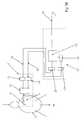
- This figure represents, in block diagram form, a system 13 for acquiring at least one electrophysiological signal SP of a living subject 2 subject to examination by an MRI examination.
- This system 13 comprises in particular a unit 14 for management and processing and at least one sensor device 1 connected to said unit, said at least one sensor device 1 being positioned on the subject 2 and the processing unit being located at a distance.
- the or each sensor device 1 (only one is represented on the Figure 2A ), fed for example by a battery, a battery or a light energy, allows the collection of the ECG of a subject 2 with the aid of two electrodes 3 connected to the housing 1 'via two conductors 3' preferably the shortest possible.
- a stage or module 4 comprising at least one instrumentation amplifier and a filtering device, together forming the preprocessing means, delivers the ECG signal (SP) with the desired gain, dynamics and bandwidth.
- SP ECG signal
- the stage or module 8 carries out shaping of the SM signals from the Hall sensors 7 with the desired gain, dynamics and bandwidth (pretreatment means).
- the two or three measured signals are, in modules common to the two acquisition chains (10, MUX, 11), multiplexed (in MUX), then modulated (in 10) (for example modulation of pulse width) in such a way to be able to be transmitted in series on a single optical fiber 15 after electronic / optical transformation E / O (in 11).
- the optical fiber 15 connects the sensor device 1 and the processing unit 14, which can be placed at a distance.
- optical signals are rendered in electronic form in an O / E conversion module 17 and transmitted to a processing module 14 'to be demultiplexed, demodulated and digitized.
- the processing for suppressing interference is performed from these digitized data.
- the synchronization of the serial link 15, 15 'between the or each sensor device 1 and the processing unit 14 is ensured by a clock 18 transmitted by the optical fiber 15' after electrical / optical I / O transformation in a module 17 ' adapted and used after optical / electrical transformation O / E (at 11 ') for controlling the modulator 10 and the multiplexer MUX, via the counter 19.
- the management and processing unit 14 is connected to the or each sensor device 1 by a bidirectional serial link 15, 15 'allowing the transmission of the or each physiological signal SP collected by the sensor device (s). (s) 1, and optionally said at least one measurement signal SM of at least one characteristic of the magnetic environment at the measurement point (s) 9 of the sensor device 1 concerned, to said unit 14 and the transmission 15 'of a clock signal of this unit 14 to said one or more sensor device (s) 1, in particular for modulation and multiplexing, signals collected by the or each sensor device 1.
- the management and processing unit 14 comprises at least one means for editing the or each physiological signal SP collected, for example display means and / or printing means, as well as storage means.
- the management and processing unit provide the MRI apparatus with a timing signal extracted from the physiological signal SP collected by means of a suitable transmission link 20.
- Treatments for correcting magnetic interference can be made according to algorithmic techniques similar to those already known (see publications cited above). Other methods are possible, however.
- the sensors 7 are integrated with the pretreatment modules 4 and 8 of the SP and SM signals, as well as with the MUX and modulation 10 multiplexing circuits, in the same microelectronic circuit 21 mounted in the a housing 1 'connected to or carrying the electrodes 3, or integrated in them.
- This circuit 21 may also include, where appropriate, the means 12 performing the correction of the signal or signals SP as a function of the signal or SM signals (in software, hardware or hardware and software).
- the invention relates to a method, a sensor device and an acquisition system comprising such a sensor device, for reducing or even eliminating the artifacts affecting the electrophysiological signals and which are due to magnetic fields.
- the invention it is therefore particularly possible to perform a local measurement of magnetic fields and magnetic field gradients, which allows a more accurate correction of interference related to magnetic field gradients, these corrections may, for example, use processing algorithms already known in the context of prior techniques based on the knowledge of the generation currents of magnetic field gradients.
Landscapes
- Health & Medical Sciences (AREA)
- Life Sciences & Earth Sciences (AREA)
- Physics & Mathematics (AREA)
- Surgery (AREA)
- General Health & Medical Sciences (AREA)
- Engineering & Computer Science (AREA)
- Biomedical Technology (AREA)
- Heart & Thoracic Surgery (AREA)
- Medical Informatics (AREA)
- Molecular Biology (AREA)
- Biophysics (AREA)
- Animal Behavior & Ethology (AREA)
- Pathology (AREA)
- Public Health (AREA)
- Veterinary Medicine (AREA)
- Nuclear Medicine, Radiotherapy & Molecular Imaging (AREA)
- High Energy & Nuclear Physics (AREA)
- Radiology & Medical Imaging (AREA)
- Magnetic Resonance Imaging Apparatus (AREA)
- Measurement And Recording Of Electrical Phenomena And Electrical Characteristics Of The Living Body (AREA)
- Investigating Or Analyzing Materials By The Use Of Electric Means (AREA)
Claims (19)
- Verfahren zur Erfassung mindestens eines physiologischen Signals eines Lebewesens, das mindestens einem elektromagnetischen Feld ausgesetzt ist, insbesondere einer elektromagnetischen Umgebung, wie sie in einem Untersuchungsgerät besteht, das mit Magnetresonanz arbeitet, mit Hilfe einer Sensorvorrichtung, darin bestehend, eine physikalische Erfassung mindestens eines elektrophysiologischen Signals am Lebewesen vorzunehmen und mindestens eine Vorbehandlung des genannten erfassten mindestens einen elektrophysiologischen Signals mit Hilfe entsprechender Mittel,
Verfahren, dadurch gekennzeichnet, dass es außerdem darin besteht, mit Hilfe zusätzlicher Mittel (7, 8) eine Messung mindestens einer Kenngröße der elektromagnetischen Umgebung auf dem Niveau oder in unmittelbarer Nähe des oder der Punkte oder Bereiche (9) der Erfassung des oder der elektrophysiologischen Signale (SP) am Lebewesen (2) vorzunehmen und das oder jedes erfasste und vorbehandelte elektrophysiologische Signal (SP) in Abhängigkeit vom genannten mindestens einen, gegebenenfalls vorbehandelten Messsignal (SM) mindestens einer Kenngröße des oder der Punkte oder Bereiche (9) der Erfassung des genannten Signals (SP) zu korrigieren, Kenngröße, ausgewählt aus der Gruppe, bestehend aus der Amplitude des lokalen magnetischen Feldvektors in einer oder mehreren Richtungen und dem Wert des oder der vorhandenen Magnetfeldgradienten in einer oder mehreren Richtungen. - Verfahren nach Patentanspruch 1, dadurch gekennzeichnet, dass es darin besteht, außerdem mit geeigneten Mitteln (10, 11) eine Modulation, eine Anpassung an die Übertragungsart und eine Sendung des genannten mindestens einen vorbehandelten elektrophysiologischen Signals (SP) und des genannten mindestens einen, gegebenenfalls ebenfalls vorbehandelten, Messsignals (SM) mindestens einer Kenngröße der elektromagnetischen Umgebung des oder der Punkte oder Bereiche der Erfassung (9) des genannten Signals (SP) zu einer fernen Steuer- und Verarbeitungseinheit (14) vorzunehmen, die gegebenenfalls mit Druck- und/oder Anzeigemitteln verbunden ist, wobei die genannte Einheit (14) ebenfalls die Korrektur des Signals (SP) in Abhängigkeit vom Messsignal (SM) vornimmt.
- Verfahren nach Patentanspruch 1, dadurch gekennzeichnet, dass es außerdem darin besteht, die Korrektur des oder jedes elektrophysiologischen Signals (SP) in Abhängigkeit vom genannten mindestens einen Messsignal (SM) mit Hilfe eines geeigneten Mittels (12) vorzunehmen, das in die Sensorvorrichtung (1) eingebaut ist, und danach mit geeigneten Mitteln (10, 11) eine Modulation, eine Anpassung an die Übertragungsart und eine Sendung zu einer fernen Steuer- und Verarbeitungseinheit (14) vorzunehmen, die gegebenenfalls mit Druck- und/oder Anzeigemitteln des genannten mindestens einen korrigierten elektrophysiologischen Signals (SP) verbunden ist.
- Sensorvorrichtung mindestens eines physiologischen Signals eines Lebewesens, das mindestens einem elektromagnetischen Feld ausgesetzt ist, insbesondere einer elektromagnetischen Umgebung, wie sie in einem Untersuchungsgerät besteht, das mit Magnetresonanz arbeitet, Mittel zur physikalischen Erfassung mindestens eines elektrophysiologischen Signals am Lebewesen, wie etwa Elektroden, umfassend und mindestens Mittel zur Vorbehandlung des genannten erfassten mindestens einen elektrophysiologischen Signals, Sensorvorrichtung (1), dadurch gekennzeichnet, dass sie auch zusätzliche Mittel (7, 8) zur Messung mindestens einer Kenngröße der elektromagnetischen Umgebung auf dem Niveau oder in unmittelbarer Nähe des oder der Punkte oder Bereiche (9) der Erfassung des oder der elektrophysiologischen Signals/e (SP) am Lebewesen (2) umfasst, wobei die genannte Kenngröße aus der Gruppe ausgewählt wird, bestehend aus der Amplitude des lokalen magnetischen Feldvektors in einer oder mehreren Richtungen und dem Wert des oder der vorhandenen Magnetfeldgradienten in einer oder mehreren Richtungen.
- Sensorvorrichtung nach Patentanspruch 4, dadurch gekennzeichnet, dass die zusätzlichen Mittel mindestens einen Magnetfeldsensor (7) umfassen, der ein Messsignal (SM) in Abhängigkeit von der Amplitude des magnetischen Feldvektors auf dem Niveau des genannten Sensors (7) ausgibt, und mindestens ein Mittel (8) zur Vorbehandlung des von dem oder jedem Sensor (7) ausgegebenen Signals.
- Sensorvorrichtung nach irgendeinem der Patentansprüche 4 und 5, dadurch gekennzeichnet, dass sie mehrere Magnetfeldsensoren (7) umfasst, die kombiniert verwendet werden, beispielsweise mindestens ein Paar Magnetfeldsensoren (7), die in einer festgelegten Richtung im Abstand voneinander angeordnet sind.
- Sensorvorrichtung nach irgendeinem der Patentansprüche 4 bis 6, dadurch gekennzeichnet, dass die zusätzlichen Mittel mindestens einen Magnetfeldsensor (7) in Form eines Hall-Effekt-Sensors umfassen oder mehrere Magnetfeldsensoren (7) in Form mehrerer Hall-Effekt-Sensoren, die kombiniert verwendet werden, beispielsweise mindestens ein Paar Magnetfeldsensoren in Form von zwei Hall-Effekt-Sensoren (7), die in einer festgelegten Richtung im Abstand voneinander angeordnet sind.
- Sensorvorrichtung nach irgendeinem der Patentansprüche 4 bis 7, dadurch gekennzeichnet, dass sie außerdem Mittel (10, 11) zur Modulation, Anpassung an die Übertragungsart und Sendung des genannten mindestens einen vorbehandelten elektrophysiologischen Signals (SP) und des genannten mindestens einen, gegebenenfalls ebenfalls vorbehandelten, Messsignals (SM) mindestens einer Kenngröße der elektromagnetischen Umgebung des oder der Punkte oder Bereiche der Erfassung (9) des genannten Signals (SP), umfasst.
- Sensorvorrichtung nach irgendeinem der Patentansprüche 4 bis 7, dadurch gekennzeichnet, dass sie außerdem einerseits ein Mittel (12) zur Korrektur des oder jedes erfassten und vorbehandelten elektrophysiologischen Signals (SP) in Abhängigkeit vom genannten gegebenenfalls vorbehandelten Messsignal (SM) mindestens einer Kenngröße der elektromagnetischen Umgebung des oder der Punkte oder Bereiche der Erfassung (9) des genannten Signals (SP) umfasst und andererseits ein Mittel (10, 11) zur Modulation, Anpassung an die Übertragungsart und Sendung des genannten mindestens einen korrigierten elektrophysiologischen Signals (SP).
- Sensorvorrichtung nach irgendeinem der Patentansprüche 4 bis 9, dadurch gekennzeichnet, dass die Mittel zur Vorbehandlung (4; 5, 6) des genannten erfassten mindestens einen elektrophysiologischen Signals (SP) und die zusätzlichen Mittel (7, 8), sowie gegebenenfalls die Mittel (10, 11) zur Modulation und Anpassung an die Übertragungsart und das Korrekturmittel (12) in Form integrierter mikroelektronischer Bauteile ausgeführt sind.
- Sensorvorrichtung nach irgendeinem der Patentansprüche 4 bis 10, dadurch gekennzeichnet, dass sie mehrere Kanäle zur Erfassung und Vorbehandlung elektrophysiologischer Signale (SP) umfasst und mehrere Kanäle zur Messung von Kenngrößen der elektromagnetischen Umgebung, was insbesondere die Bestimmung von Gradienten des magnetischen Feldes längs den drei Achsen eines rechtwinkligen Koordinatensystems ermöglicht, das mit der genannten Sensorvorrichtung (1) verbunden ist.
- Sensorvorrichtung nach irgendeinem der Patentansprüche 8 und 9, dadurch gekennzeichnet, dass die Übertragung des oder der vorbehandelten oder vorbehandelten und korrigierten elektrophysiologischen Signale (SP) und gegebenenfalls des oder der Messsignale (SM) des Magnetfeldes oder von Gradienten des Magnetfeldes, in einer seriellen Übertragungsart erfolgt, ausgewählt aus der Gruppe, bestehend aus der Übertragung über Lichtleiter, der Übertragung über Radiowellen und der Übertragung über abgeschirmte elektrische Leiter.
- Sensorvorrichtung nach irgendeinem der Patentansprüche 5 bis 7, dadurch gekennzeichnet, dass jeder Sensor (7) aus einem Hall-Sensor in Form einer mikroelektronischen Standard-CMOS-Halbleiterschaltung besteht, vorzugsweise des Typs, der eine Oberfläche von einigen mm2 aufweist und eine Messgenauigkeit in der Größenordnung von 10 bis 100 Mikrotesla.
- Sensorvorrichtung nach Patentanspruch 13, dadurch gekennzeichnet, dass die Sensoren (7) mit den Vorbehandlungsmodulen (4 und 8) der Signale (SP und SM), sowie mit den Multiplexerschaltungen (MUX) und den Modulationsschaltungen (10) in ein und derselben mikroelektronischen Schaltung (21) integriert sind, die in einem Gehäuse (1') montiert ist, das mit den Elektroden (3) verbunden ist oder diese trägt oder auch in diese eingebaut ist.
- Sensorvorrichtung nach den Patentansprüchen 9 und 14, dadurch gekennzeichnet, dass die Schaltung (21) ebenfalls das Korrekturmittel (12) enthält.
- System zur Erfassung mindestens eines elektrophysiologischen Signals eines Lebewesens, an dem eine NMR-Untersuchung vorgenommen wird, insbesondere zur Ausführung des Verfahrens nach irgendeinem der Patentansprüche 1 bis 3, wobei dieses System insbesondere eine Steuer- und Verarbeitungseinheit umfasst und mindestens eine Sensorvorrichtung, die mit der genannten Einheit verbunden ist, wobei die genannte mindestens eine Sensorvorrichtung am Lebewesen angeordnet ist und sich die Verarbeitungseinheit fern davon befindet, System (13), dadurch gekennzeichnet, dass die oder jede Sensorvorrichtung (1) eine Sensorvorrichtung nach irgendeinem der Patentansprüche 4 bis 15 ist.
- System nach Patentanspruch 16, dadurch gekennzeichnet, dass die Steuer- und Verarbeitungseinheit (14) über eine serielle Zweirichtungsverbindung (15, 15') mit der oder jeder Sensorvorrichtung (1) verbunden ist, die die Übertragung (15) des oder jedes von der oder den Sensorvorrichtung(en) (1) erfassten physiologischen Signals (SP) und gegebenenfalls des genannten mindestens einen Messsignals (SM) mindestens einer Kenngröße der magnetischen Umgebung auf dem Niveau des oder der Messpunkte (9) der betreffenden Sensorvorrichtung (1) zur genannten Einheit (14) erlaubt und die Übertragung (15') eines Taktsignals dieser Einheit (14) zu der oder den genannten Sensorvorrichtung(en) (1), insbesondere zur Modulation und zum Multiplexen der durch die oder jede Sensorvorrichtung (1) erfassten Signale.
- System nach Patentanspruch 16 oder 17, dadurch gekennzeichnet, dass die Steuer- und Verarbeitungseinheit (14) mindestens ein Ausgabemittel des oder jedes erfassten physiologischen Signals (SP) umfasst, beispielsweise ein Anzeige- und/oder ein Druckmittel.
- System nach irgendeinem der Patentansprüche 16 bis 18, dadurch gekennzeichnet, dass die Steuer- und Verarbeitungseinheit an das NMR-Gerät ein Wiederholungsratensignal abgibt, das aus dem erfassten physiologischen Signal (SP) abgeleitet wurde.
Applications Claiming Priority (2)
| Application Number | Priority Date | Filing Date | Title |
|---|---|---|---|
| FR0754747A FR2915365B1 (fr) | 2007-04-27 | 2007-04-27 | Procede, dispositif et systeme pour reduire les artefacts affectant les signaux electrophysiologiques et dus aux champs electromagnetiques |
| PCT/FR2008/050751 WO2008155488A2 (fr) | 2007-04-27 | 2008-04-25 | Procede, dispositif et systeme pour reduire les artefacts affectant les signaux electrophysiologiques et dus aux champs electromagnetiques |
Publications (2)
| Publication Number | Publication Date |
|---|---|
| EP2152157A2 EP2152157A2 (de) | 2010-02-17 |
| EP2152157B1 true EP2152157B1 (de) | 2016-04-13 |
Family
ID=38521680
Family Applications (1)
| Application Number | Title | Priority Date | Filing Date |
|---|---|---|---|
| EP08805705.4A Active EP2152157B1 (de) | 2007-04-27 | 2008-04-25 | Verfahren, vorrichtung und system zur reduzierung von artefakten, die elektrophysiologische signale beeinträchtigen und von elektromagnetischen feldern verursacht werden |
Country Status (4)
| Country | Link |
|---|---|
| US (1) | US20100191095A1 (de) |
| EP (1) | EP2152157B1 (de) |
| FR (1) | FR2915365B1 (de) |
| WO (1) | WO2008155488A2 (de) |
Families Citing this family (14)
| Publication number | Priority date | Publication date | Assignee | Title |
|---|---|---|---|---|
| DE102011076885B4 (de) * | 2011-06-01 | 2013-08-29 | Siemens Aktiengesellschaft | Verfahren zur Steuerung eines medizinischen Gerätes, Einrichtung mit einem medizinischen Gerät und Datenträger |
| DE102011076880A1 (de) * | 2011-06-01 | 2012-12-06 | Siemens Aktiengesellschaft | Verfahren zur Steuerung eines medizinischen Gerätes, Einrichtung mit einem medizinischen Gerät und Datenträger |
| FR3002046B1 (fr) * | 2013-02-14 | 2015-04-03 | Univ Claude Bernard Lyon | Procede et dispositif de mesure pour des applications de resonance magnetique |
| EP3018488B1 (de) | 2014-11-06 | 2023-06-07 | Université de Lorraine | MRT-Vorrichtung und Verfahren zur Erkennung implantierter Herzschrittmacher |
| WO2019060298A1 (en) | 2017-09-19 | 2019-03-28 | Neuroenhancement Lab, LLC | METHOD AND APPARATUS FOR NEURO-ACTIVATION |
| US11717686B2 (en) | 2017-12-04 | 2023-08-08 | Neuroenhancement Lab, LLC | Method and apparatus for neuroenhancement to facilitate learning and performance |
| US12280219B2 (en) | 2017-12-31 | 2025-04-22 | NeuroLight, Inc. | Method and apparatus for neuroenhancement to enhance emotional response |
| US11478603B2 (en) | 2017-12-31 | 2022-10-25 | Neuroenhancement Lab, LLC | Method and apparatus for neuroenhancement to enhance emotional response |
| FR3080020B1 (fr) * | 2018-04-12 | 2020-04-24 | Schiller Medical | Procede et dispositif de correction en temps reel de champ magnetique. |
| US11364361B2 (en) | 2018-04-20 | 2022-06-21 | Neuroenhancement Lab, LLC | System and method for inducing sleep by transplanting mental states |
| US11452839B2 (en) | 2018-09-14 | 2022-09-27 | Neuroenhancement Lab, LLC | System and method of improving sleep |
| FR3087332B1 (fr) | 2018-10-23 | 2020-11-06 | Schiller Medical | Procede de correction en temps reel d'au moins un signal electro-physiologique. |
| US11786694B2 (en) | 2019-05-24 | 2023-10-17 | NeuroLight, Inc. | Device, method, and app for facilitating sleep |
| AT523903B1 (de) * | 2020-06-12 | 2023-02-15 | Matissek Msc Michael | Umwelt-/Gesundheitsmonitoringsystem zur Erfassung von elektromagnetischen Feldern und der Beeinflussung vegetativer Regulationsmechanismen des menschlichen Organismus |
Family Cites Families (11)
| Publication number | Priority date | Publication date | Assignee | Title |
|---|---|---|---|---|
| US4991580A (en) * | 1989-03-30 | 1991-02-12 | Invivo Research, Inc. | Method of improving the quality of an electrocardiogram obtained from a patient undergoing magnetic resonance imaging |
| FR2704131B1 (fr) * | 1993-04-22 | 1995-06-30 | Odam | Dispositif capteur pour électrocardiogramme. |
| US5445162A (en) * | 1993-08-27 | 1995-08-29 | Beth Israel Hospital Association | Apparatus and method for recording an electroencephalogram during magnetic resonance imaging |
| FR2729071B1 (fr) * | 1995-01-09 | 1997-06-20 | Odam Office De Distribution D | Dispositif capteur delivrant notamment un signal representatif de la respiration d'un patient |
| FR2793131B1 (fr) * | 1999-05-07 | 2001-08-03 | Bruker Medical Sa | Procede et dispositif pour l'acquisition de l'electrocardiogramme |
| US6675036B2 (en) * | 2001-07-18 | 2004-01-06 | Ge Medical Systems, Inc. | Diagnostic device including a method and apparatus for bio-potential noise cancellation utilizing the patient's respiratory signal |
| US20050277826A1 (en) * | 2004-06-10 | 2005-12-15 | Conopco, Inc. | Apparatus and method for reducing interference |
| DE102004037375A1 (de) * | 2004-08-02 | 2006-03-30 | Siemens Ag | Physiologisches Sensorsystem |
| US20050154425A1 (en) * | 2004-08-19 | 2005-07-14 | Boveja Birinder R. | Method and system to provide therapy for neuropsychiatric disorders and cognitive impairments using gradient magnetic pulses to the brain and pulsed electrical stimulation to vagus nerve(s) |
| EP1954189A4 (de) * | 2005-11-17 | 2012-05-23 | Brain Res Inst Pty Ltd | Vorrichtung und verfahren zur erkennung und überwachung elektrischer aktivitäten und bewegungen in der umgebung eines magnetischen feldes |
| EP1872717B1 (de) * | 2006-06-29 | 2010-09-08 | General Electric Company | Medizinisches Telemetriesystem |
-
2007
- 2007-04-27 FR FR0754747A patent/FR2915365B1/fr not_active Expired - Fee Related
-
2008
- 2008-04-25 EP EP08805705.4A patent/EP2152157B1/de active Active
- 2008-04-25 US US12/597,798 patent/US20100191095A1/en not_active Abandoned
- 2008-04-25 WO PCT/FR2008/050751 patent/WO2008155488A2/fr not_active Ceased
Also Published As
| Publication number | Publication date |
|---|---|
| FR2915365A1 (fr) | 2008-10-31 |
| WO2008155488A3 (fr) | 2009-03-26 |
| FR2915365B1 (fr) | 2010-09-10 |
| US20100191095A1 (en) | 2010-07-29 |
| WO2008155488A2 (fr) | 2008-12-24 |
| EP2152157A2 (de) | 2010-02-17 |
Similar Documents
| Publication | Publication Date | Title |
|---|---|---|
| EP2152157B1 (de) | Verfahren, vorrichtung und system zur reduzierung von artefakten, die elektrophysiologische signale beeinträchtigen und von elektromagnetischen feldern verursacht werden | |
| EP1050270B1 (de) | Verfahren und Vorrichtung zur Erfassung von Elektrokardiogrammen | |
| US20190083048A1 (en) | Massively Multi-Frequency Ultrasound-Encoded Tomography | |
| US20090012387A1 (en) | Encoding and transmission of signals as rf signals for detection using an mr apparatus | |
| US11363988B2 (en) | Systems and methods for accelerated MRI scan | |
| US10682081B2 (en) | Acquiring and processing non-contact functional near-infrared spectroscopy data | |
| EP2980706A1 (de) | Lokalisierungsverfahren einer mit einer aufgabe verbundenen gehirnaktivität | |
| EP0721110B1 (de) | Sensor besonders zur Abgabe eines Signales zur Darstellung der Atmung eines Patienten | |
| JP2022511065A (ja) | 機能的磁気共鳴イメージングアーチファクト除去 | |
| Chen et al. | WISDEM: a hybrid wireless integrated sensing detector for simultaneous EEG and MRI | |
| EP3552545B1 (de) | Verfahren und vorrichtung zur magnetfeldkorrektur in echtzeit | |
| Tasdelen et al. | Contactless cardiac gating at 0.55 T using high‐amplitude pilot tone with interference cancellation (HAPTIC) | |
| WO2012107692A1 (fr) | Capteur de mouvement associe a une electrode de diagnostic pour applications en imagerie medicale | |
| US20250064309A1 (en) | Strategy and technological implementations for concurrent fluorescence measurements of multiple biological parameters in behaving animals | |
| US20130321819A1 (en) | Apparatus and method for generating tomographic image | |
| Chaudhary et al. | Implementation and evaluation of simultaneous video-electroencephalography and functional magnetic resonance imaging | |
| Beedholm et al. | Latencies of click-evoked auditory responses in a harbor porpoise exceed the time interval between subsequent echolocation clicks | |
| FR2930420A1 (fr) | Procede et systeme non invasif de detection et d'evaluation de l'activite electrophysiologique neuronale | |
| EP3298421B1 (de) | Herstellungsmodul und -verfahren, bildgebungsvorrichtung und -verfahren sowie mrt- und/oder mrs-programme | |
| JP2005328855A (ja) | 生体光計測装置、画像表示方法およびプログラム | |
| Webb et al. | High speed microcircuit and synthetic biosignal widefield imaging using nitrogen vacancies in diamond | |
| EP4100753A1 (de) | Anordnung von magnetometern, die im nullfeld arbeiten, und zugehöriges verfahren zum kalibrieren von kopplungen zwischen magnetometern | |
| CN120694602B (zh) | 一种脑磁兼容的多通道近红外高采样率调制方法及系统 | |
| EP2769199A1 (de) | Implantierbare bildgebungsanordnung und verfahren zu ihrer verwendung | |
| EP0406082A1 (de) | Verfahren zur dreidimensionalen Bilderzeugung mittels magnetischer Kernresonanz |
Legal Events
| Date | Code | Title | Description |
|---|---|---|---|
| PUAI | Public reference made under article 153(3) epc to a published international application that has entered the european phase |
Free format text: ORIGINAL CODE: 0009012 |
|
| 17P | Request for examination filed |
Effective date: 20091119 |
|
| AK | Designated contracting states |
Kind code of ref document: A2 Designated state(s): AT BE BG CH CY CZ DE DK EE ES FI FR GB GR HR HU IE IS IT LI LT LU LV MC MT NL NO PL PT RO SE SI SK TR |
|
| AX | Request for extension of the european patent |
Extension state: AL BA MK RS |
|
| DAX | Request for extension of the european patent (deleted) | ||
| 17Q | First examination report despatched |
Effective date: 20121123 |
|
| REG | Reference to a national code |
Ref country code: DE Ref legal event code: R079 Ref document number: 602008043582 Country of ref document: DE Free format text: PREVIOUS MAIN CLASS: A61B0005055000 Ipc: A61B0005040000 |
|
| GRAP | Despatch of communication of intention to grant a patent |
Free format text: ORIGINAL CODE: EPIDOSNIGR1 |
|
| RIC1 | Information provided on ipc code assigned before grant |
Ipc: A61B 5/055 20060101ALI20150925BHEP Ipc: A61B 5/04 20060101AFI20150925BHEP |
|
| INTG | Intention to grant announced |
Effective date: 20151023 |
|
| GRAS | Grant fee paid |
Free format text: ORIGINAL CODE: EPIDOSNIGR3 |
|
| GRAA | (expected) grant |
Free format text: ORIGINAL CODE: 0009210 |
|
| AK | Designated contracting states |
Kind code of ref document: B1 Designated state(s): AT BE BG CH CY CZ DE DK EE ES FI FR GB GR HR HU IE IS IT LI LT LU LV MC MT NL NO PL PT RO SE SI SK TR |
|
| REG | Reference to a national code |
Ref country code: GB Ref legal event code: FG4D Free format text: NOT ENGLISH |
|
| REG | Reference to a national code |
Ref country code: AT Ref legal event code: REF Ref document number: 789164 Country of ref document: AT Kind code of ref document: T Effective date: 20160415 Ref country code: CH Ref legal event code: EP |
|
| REG | Reference to a national code |
Ref country code: IE Ref legal event code: FG4D Free format text: LANGUAGE OF EP DOCUMENT: FRENCH |
|
| REG | Reference to a national code |
Ref country code: DE Ref legal event code: R096 Ref document number: 602008043582 Country of ref document: DE |
|
| REG | Reference to a national code |
Ref country code: FR Ref legal event code: PLFP Year of fee payment: 9 |
|
| REG | Reference to a national code |
Ref country code: LT Ref legal event code: MG4D |
|
| PG25 | Lapsed in a contracting state [announced via postgrant information from national office to epo] |
Ref country code: BE Free format text: LAPSE BECAUSE OF NON-PAYMENT OF DUE FEES Effective date: 20160430 |
|
| REG | Reference to a national code |
Ref country code: AT Ref legal event code: MK05 Ref document number: 789164 Country of ref document: AT Kind code of ref document: T Effective date: 20160413 |
|
| REG | Reference to a national code |
Ref country code: NL Ref legal event code: MP Effective date: 20160413 |
|
| PG25 | Lapsed in a contracting state [announced via postgrant information from national office to epo] |
Ref country code: FI Free format text: LAPSE BECAUSE OF FAILURE TO SUBMIT A TRANSLATION OF THE DESCRIPTION OR TO PAY THE FEE WITHIN THE PRESCRIBED TIME-LIMIT Effective date: 20160413 Ref country code: NL Free format text: LAPSE BECAUSE OF FAILURE TO SUBMIT A TRANSLATION OF THE DESCRIPTION OR TO PAY THE FEE WITHIN THE PRESCRIBED TIME-LIMIT Effective date: 20160413 Ref country code: PL Free format text: LAPSE BECAUSE OF FAILURE TO SUBMIT A TRANSLATION OF THE DESCRIPTION OR TO PAY THE FEE WITHIN THE PRESCRIBED TIME-LIMIT Effective date: 20160413 Ref country code: LT Free format text: LAPSE BECAUSE OF FAILURE TO SUBMIT A TRANSLATION OF THE DESCRIPTION OR TO PAY THE FEE WITHIN THE PRESCRIBED TIME-LIMIT Effective date: 20160413 Ref country code: NO Free format text: LAPSE BECAUSE OF FAILURE TO SUBMIT A TRANSLATION OF THE DESCRIPTION OR TO PAY THE FEE WITHIN THE PRESCRIBED TIME-LIMIT Effective date: 20160713 |
|
| PG25 | Lapsed in a contracting state [announced via postgrant information from national office to epo] |
Ref country code: HR Free format text: LAPSE BECAUSE OF FAILURE TO SUBMIT A TRANSLATION OF THE DESCRIPTION OR TO PAY THE FEE WITHIN THE PRESCRIBED TIME-LIMIT Effective date: 20160413 Ref country code: AT Free format text: LAPSE BECAUSE OF FAILURE TO SUBMIT A TRANSLATION OF THE DESCRIPTION OR TO PAY THE FEE WITHIN THE PRESCRIBED TIME-LIMIT Effective date: 20160413 Ref country code: LV Free format text: LAPSE BECAUSE OF FAILURE TO SUBMIT A TRANSLATION OF THE DESCRIPTION OR TO PAY THE FEE WITHIN THE PRESCRIBED TIME-LIMIT Effective date: 20160413 Ref country code: ES Free format text: LAPSE BECAUSE OF FAILURE TO SUBMIT A TRANSLATION OF THE DESCRIPTION OR TO PAY THE FEE WITHIN THE PRESCRIBED TIME-LIMIT Effective date: 20160413 Ref country code: SE Free format text: LAPSE BECAUSE OF FAILURE TO SUBMIT A TRANSLATION OF THE DESCRIPTION OR TO PAY THE FEE WITHIN THE PRESCRIBED TIME-LIMIT Effective date: 20160413 Ref country code: PT Free format text: LAPSE BECAUSE OF FAILURE TO SUBMIT A TRANSLATION OF THE DESCRIPTION OR TO PAY THE FEE WITHIN THE PRESCRIBED TIME-LIMIT Effective date: 20160816 Ref country code: GR Free format text: LAPSE BECAUSE OF FAILURE TO SUBMIT A TRANSLATION OF THE DESCRIPTION OR TO PAY THE FEE WITHIN THE PRESCRIBED TIME-LIMIT Effective date: 20160714 |
|
| REG | Reference to a national code |
Ref country code: CH Ref legal event code: PL |
|
| PG25 | Lapsed in a contracting state [announced via postgrant information from national office to epo] |
Ref country code: IT Free format text: LAPSE BECAUSE OF FAILURE TO SUBMIT A TRANSLATION OF THE DESCRIPTION OR TO PAY THE FEE WITHIN THE PRESCRIBED TIME-LIMIT Effective date: 20160413 |
|
| REG | Reference to a national code |
Ref country code: DE Ref legal event code: R097 Ref document number: 602008043582 Country of ref document: DE |
|
| REG | Reference to a national code |
Ref country code: IE Ref legal event code: MM4A |
|
| PG25 | Lapsed in a contracting state [announced via postgrant information from national office to epo] |
Ref country code: EE Free format text: LAPSE BECAUSE OF FAILURE TO SUBMIT A TRANSLATION OF THE DESCRIPTION OR TO PAY THE FEE WITHIN THE PRESCRIBED TIME-LIMIT Effective date: 20160413 Ref country code: SK Free format text: LAPSE BECAUSE OF FAILURE TO SUBMIT A TRANSLATION OF THE DESCRIPTION OR TO PAY THE FEE WITHIN THE PRESCRIBED TIME-LIMIT Effective date: 20160413 Ref country code: DK Free format text: LAPSE BECAUSE OF FAILURE TO SUBMIT A TRANSLATION OF THE DESCRIPTION OR TO PAY THE FEE WITHIN THE PRESCRIBED TIME-LIMIT Effective date: 20160413 Ref country code: CH Free format text: LAPSE BECAUSE OF NON-PAYMENT OF DUE FEES Effective date: 20160430 Ref country code: CZ Free format text: LAPSE BECAUSE OF FAILURE TO SUBMIT A TRANSLATION OF THE DESCRIPTION OR TO PAY THE FEE WITHIN THE PRESCRIBED TIME-LIMIT Effective date: 20160413 Ref country code: RO Free format text: LAPSE BECAUSE OF FAILURE TO SUBMIT A TRANSLATION OF THE DESCRIPTION OR TO PAY THE FEE WITHIN THE PRESCRIBED TIME-LIMIT Effective date: 20160413 Ref country code: MC Free format text: LAPSE BECAUSE OF FAILURE TO SUBMIT A TRANSLATION OF THE DESCRIPTION OR TO PAY THE FEE WITHIN THE PRESCRIBED TIME-LIMIT Effective date: 20160413 Ref country code: LI Free format text: LAPSE BECAUSE OF NON-PAYMENT OF DUE FEES Effective date: 20160430 |
|
| PLBE | No opposition filed within time limit |
Free format text: ORIGINAL CODE: 0009261 |
|
| STAA | Information on the status of an ep patent application or granted ep patent |
Free format text: STATUS: NO OPPOSITION FILED WITHIN TIME LIMIT |
|
| 26N | No opposition filed |
Effective date: 20170116 |
|
| REG | Reference to a national code |
Ref country code: FR Ref legal event code: PLFP Year of fee payment: 10 |
|
| PG25 | Lapsed in a contracting state [announced via postgrant information from national office to epo] |
Ref country code: SI Free format text: LAPSE BECAUSE OF FAILURE TO SUBMIT A TRANSLATION OF THE DESCRIPTION OR TO PAY THE FEE WITHIN THE PRESCRIBED TIME-LIMIT Effective date: 20160413 Ref country code: IE Free format text: LAPSE BECAUSE OF NON-PAYMENT OF DUE FEES Effective date: 20160425 |
|
| REG | Reference to a national code |
Ref country code: FR Ref legal event code: PLFP Year of fee payment: 11 |
|
| PG25 | Lapsed in a contracting state [announced via postgrant information from national office to epo] |
Ref country code: HU Free format text: LAPSE BECAUSE OF FAILURE TO SUBMIT A TRANSLATION OF THE DESCRIPTION OR TO PAY THE FEE WITHIN THE PRESCRIBED TIME-LIMIT; INVALID AB INITIO Effective date: 20080425 Ref country code: CY Free format text: LAPSE BECAUSE OF FAILURE TO SUBMIT A TRANSLATION OF THE DESCRIPTION OR TO PAY THE FEE WITHIN THE PRESCRIBED TIME-LIMIT Effective date: 20160413 |
|
| PG25 | Lapsed in a contracting state [announced via postgrant information from national office to epo] |
Ref country code: MT Free format text: LAPSE BECAUSE OF FAILURE TO SUBMIT A TRANSLATION OF THE DESCRIPTION OR TO PAY THE FEE WITHIN THE PRESCRIBED TIME-LIMIT Effective date: 20160413 Ref country code: LU Free format text: LAPSE BECAUSE OF NON-PAYMENT OF DUE FEES Effective date: 20160425 Ref country code: IS Free format text: LAPSE BECAUSE OF FAILURE TO SUBMIT A TRANSLATION OF THE DESCRIPTION OR TO PAY THE FEE WITHIN THE PRESCRIBED TIME-LIMIT Effective date: 20160413 Ref country code: TR Free format text: LAPSE BECAUSE OF FAILURE TO SUBMIT A TRANSLATION OF THE DESCRIPTION OR TO PAY THE FEE WITHIN THE PRESCRIBED TIME-LIMIT Effective date: 20160413 |
|
| PG25 | Lapsed in a contracting state [announced via postgrant information from national office to epo] |
Ref country code: BG Free format text: LAPSE BECAUSE OF FAILURE TO SUBMIT A TRANSLATION OF THE DESCRIPTION OR TO PAY THE FEE WITHIN THE PRESCRIBED TIME-LIMIT Effective date: 20160413 |
|
| REG | Reference to a national code |
Ref country code: DE Ref legal event code: R079 Ref document number: 602008043582 Country of ref document: DE Free format text: PREVIOUS MAIN CLASS: A61B0005040000 Ipc: A61B0005240000 |
|
| PGFP | Annual fee paid to national office [announced via postgrant information from national office to epo] |
Ref country code: DE Payment date: 20250422 Year of fee payment: 18 |
|
| PGFP | Annual fee paid to national office [announced via postgrant information from national office to epo] |
Ref country code: GB Payment date: 20250423 Year of fee payment: 18 |
|
| PGFP | Annual fee paid to national office [announced via postgrant information from national office to epo] |
Ref country code: FR Payment date: 20250424 Year of fee payment: 18 |