EP2152189B1 - Élément de réception d'un implant - Google Patents
Élément de réception d'un implant Download PDFInfo
- Publication number
- EP2152189B1 EP2152189B1 EP08760573.9A EP08760573A EP2152189B1 EP 2152189 B1 EP2152189 B1 EP 2152189B1 EP 08760573 A EP08760573 A EP 08760573A EP 2152189 B1 EP2152189 B1 EP 2152189B1
- Authority
- EP
- European Patent Office
- Prior art keywords
- receiving element
- dental implant
- plate
- implant
- implant according
- Prior art date
- Legal status (The legal status is an assumption and is not a legal conclusion. Google has not performed a legal analysis and makes no representation as to the accuracy of the status listed.)
- Active
Links
Images

Classifications
-
- A—HUMAN NECESSITIES
- A61—MEDICAL OR VETERINARY SCIENCE; HYGIENE
- A61C—DENTISTRY; APPARATUS OR METHODS FOR ORAL OR DENTAL HYGIENE
- A61C8/00—Means to be fixed to the jaw-bone for consolidating natural teeth or for fixing dental prostheses thereon; Dental implants; Implanting tools
- A61C8/0087—Means for sterile storage or manipulation of dental implants
-
- A—HUMAN NECESSITIES
- A61—MEDICAL OR VETERINARY SCIENCE; HYGIENE
- A61C—DENTISTRY; APPARATUS OR METHODS FOR ORAL OR DENTAL HYGIENE
- A61C19/00—Dental auxiliary appliances
- A61C19/02—Protective casings, e.g. boxes for instruments; Bags
-
- A—HUMAN NECESSITIES
- A61—MEDICAL OR VETERINARY SCIENCE; HYGIENE
- A61C—DENTISTRY; APPARATUS OR METHODS FOR ORAL OR DENTAL HYGIENE
- A61C8/00—Means to be fixed to the jaw-bone for consolidating natural teeth or for fixing dental prostheses thereon; Dental implants; Implanting tools
Definitions
- the present invention relates to a receiving element for an implant, in particular for screw or cylindrical implants.
- Such implants are z. B. from dental technology and are substantially similar to a screw, wherein the apical region of the screw is inserted into a bone and the coronal region is suitable for receiving a dental prosthesis.
- holding elements mounted on the implant are additionally known in various embodiments, which on the one hand fix the implant and on the other hand allow a sterile removal from the receiving element.
- they ensure that an implant in the period from manufacture to surgery not with non-sterile means such. B. hands, come into contact.
- the relevant field of application of the invention is where the implants, z. B. reasons of required sterile operation, at least not be detected directly with the hands, and where it matters to keep the implants safely.
- Such receptacles have the function of safely transporting the implant and providing a sterile environment for storage.
- the implant is removed from the receiving element, which generally has a retaining element attached to the implant (in the following, the combination of implant and retaining element attached thereto is referred to simply as an implant structure).
- a cylindrical ampoule insertable in an outer capsule which is suitable for receiving an implant.
- the ampoule has an end region which is provided with a laterally open indentation. This indentation serves to insert an implant structure that consists of the implant and an additional holding element connected to the implant.
- the implant assembly is fixed by being pressed through an opening in a constriction in the ampoule. In order to obtain a sufficient fixation, a considerable pressure must be applied during the pressing of the implant, this has the consequence that the structural material is subject to a considerable stress, since the forces occurring along both the in the rigid structure of an ampoule and a receiving element Spread expansion groove as well along the cylinder surface.
- the front of the ampoule is also relatively narrow in cross-section and the entire holding force between an implant and the inside of the constriction is limited to this narrow area, and thus the holding or withdrawal force is increased by the pressure or compression when removing the implant from the holder.
- the handle of the implant is reinforced, so that the removal process is difficult to control.
- the cylindrical ampoule can move in a deposited position in a certain area about its axis, which makes it difficult to grasp.
- a receiving element according to the preamble of claim 1 is known from WO2005 / 037126A1 known.
- the present invention is therefore based on the object to provide a receiving element for a dental implant, which fixes a dental implant structure safer and the forces occurring when inserting the dental implant assembly on the structure of the receiving element better can implement and deduce. Furthermore, a simplified and safer handling should be provided and a cost-effective production with existing techniques possible.
- the present invention is based on the object, a receiving element for a dental implant with improved stability and force conversion to provide that avoids the above-mentioned problems.
- a further object of the present invention is to realize a receiving element for a dental implant, which is better protected against slipping on a tray.
- Another object of the present invention is that the receiving element can be simplified and handled more safely.
- Another object of the present invention is that the receiving element can be easily and inexpensively manufactured by conventional methods.
- the structural features of a substantially cylindrical receiving element according to the present invention are that the head portion holding the receiving element is almost decoupled from the trunk so as to effectively dissipate emerging forces during removal of the dental implant from the holder of the designated opening and / or even completely to eliminate.
- the substantially square trunk area is advantageously equipped with an open side for easy insertion of the dental implant.
- the head portion has a first surface suitable for clamping engagement with a dental implant and a second surface preventing contact of the dental implant with the inner wall of the body portion.
- one side of the receiving element is provided with a flat surface, the stable storage on a shelf, for. B. ensures the operating table.
- the receiving element in the trunk area on a plurality of reinforcing ribs, on the one hand reinforce the outer wall, on the other hand provide a better grip.
- a dental implant receiving member comprising a substantially cylindrical bottom portion, a trunk portion enclosing the dental implant, and a flexible head portion formed from two plates, the head portion being provided with a clamping device
- Receiving a dental implant is provided, which is adapted to fix a dental implant releasably clamped.
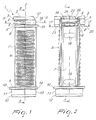
- FIG. 1 shows a receiving element 1 for a dental implant, wherein the receiving element 1 basically has three sections.
- a first portion forming the head portion consists of an approximately C-shaped, flat face 2, which comprises a first plate 3, which is suitable for fixing a dental implant (not shown), as described below in the text.
- the first plate 3 is adjoined by an open area 5 surrounded by the first step 4 adjoining the first plate 3 and an underlying second step 4 'adjacent to a second plate 6.
- the preferably mouth-like open area 5 preferably extends from its open side at a respective end of the plates 3, 6 to a theoretical center axis Z of the receiving element 1, wherein advantageously the opening width in the region of the central axis Z is less than on the outside. Through the mouth-like area 5, a mechanical decoupling of the plates 3, 6 and the first plate 3 from the hull 7 is achieved.
- a bevel 17 which is provided from an outer edge of the flat end face 2, to a flat Kopf Scheme 16, wherein the flat head portion 16 connects to a flat top edge 15, the adjacent both to the head portion 16, and to a hull 7 of the receiving element 1.
- the part of the second plate 6 underlying the mouth-like region 5 then adjoins a second section, which is formed by the fuselage 7, and which is provided with a plurality of symmetrically arranged reinforcing ribs 8. These occur from the surface of the fuselage 7 and are preferably arranged at equal distances from each other.
- these reinforcing ribs 8 are formed in an elongate shape.
- a base surface 9 connects, which is substantially circularly symmetrical, on which the hull 7 is arranged at right angles.
- the third section comprises a perimetric peripheral edge 10 embedded between the base 9 and a bottom part 11, the bottom part 11 merging on one side with the standing area 12 suitable for placement on a surface.
- a bottom portion 13, which is formed between the bottom edge 14 and the standing area 12, is advantageously flat. Adjacent to the bottom portion 13 is the bottom edge 14, which is also flat. Due to the planar embodiment of the head edge 15 and the bottom edge 14, it is possible to stably position the receiving element 1 on a shelf, and to prevent both a roll, as well as to allow easy gripping.
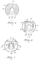
- FIG. 2 shows further features of the receiving element 1, wherein a first opening 23 and a second opening 24 are arranged centrally in the first plate 3.
- the second aperture 24 may preferably have a smaller diameter than the first aperture 23, although in the presently preferred embodiment the difference in diameter is not essential.
- the first opening 23 and the second opening 24 are connected at one point to each other by an open groove 39, as well as in Fig. 7 shown.
- At the first opening 23 closes an opening 40, see FIG. 7 , the first plate 3 on.
- a first slot 18 and a second slot 19 present.
- FIGS. 3 and 4 show further features of the receiving element 1, wherein a portion of the first plate 3 is provided with a tapered leg 22 which extends from the outer edge to approximately in the region of a theoretical center axis Z of the receiving element 1, wherein the tapered leg 22 a slight insertion of a dental implant allows. Furthermore, the first plate 3 when pressing the dental implant with respect to the second plate 6 elastically deformable in a direction perpendicular to the central axis Z of the receiving element 1 direction until the dental implant snaps into the first opening 23 and is held by clamping, with a first gap 36 and a second gap 37 of the mouth-like region 5 mechanically decouple the first plate 3 from the body 7 and from the second plate 6, as mentioned above.
- the bevel 17 located on the opposite side advantageously has a resilient effect.
- a first reinforcement 20 and a second reinforcement 21 serve to consolidate the construction under the stresses created when the dental implant is pressed in.
- a first recess 34 and a second recess 35 which may have a conical shape and which are arranged symmetrically in the first plate 3 and adjacent to the first aperture 23 and the second aperture 24, are for distributing the forces when the dental implant is pressed through the dental implant Opening 40 of the first plate 3rd suitable, and the first plate 3 is in a direction which is perpendicular to the central axis Z, elastically stretchable.
- the conical shape of the recesses is particularly preferred for manufacturing reasons, if the receiving element is manufactured by injection molding.
- the second opening 24 has, as explained above, a smaller diameter than the first opening 23 and is connected thereto with the groove 39, so that the opening 24 serves as an expansion opening and can expand when a dental implant is pressed in.
- the elastic deformability of the first plate 3 advantageously results in both a clamping connection and a snap connection, which fixes the dental implant securely in the first opening 23.
- FIGS. 5 and 6 show the head portion of the receiving element 1, wherein Fig. 5 a surface 41 which, in the region of the opening 40, see FIG. 7 , a first chamfer 26 and a second chamfer 27, which serve for easy insertion of the dental implant.
- the angle formed between the first and second chamfer is advantageously formed in the range of 80 to 120 degrees.
- the surface 41, which is trapped over the entire cross section to the chamfers 26, 27, is rigidly formed to the in Fig. 6 form U-shaped region 32 shown.
- the inner surface of the U-shaped region 32 forms a stop region 33, on which an inserted dental implant is held in a stable position, so that a contact, for. B. during transport, with the inner walls of the hull 7 is excluded.
- the base 9 off Fig.1 has in the portion of the opening 40 on a circular ring portion 25 which has approximately the width of the U-shaped portion 32, and has centrally a third opening 42, which has a larger diameter than the first and second opening
- FIG. 7 shows that the first aperture 23 is aligned with the third aperture 42.
- the first recess 34 and the second recess 35 extend in the Area of the opening 40 substantially parallel thereto, wherein they bend slightly towards the center of the second opening 24 near the first 23 and second 24 breakthrough.
- the receiving element 1 can with conventional methods, eg. B. are produced in the molding and preferably consists of an elastic plastic.
- Breakthrough 24 2nd breakthrough 25
- Annulus section 26 1st chamfer 27 2nd chamfer 28 1.
- insertion edge 29 2.
- insertion edge 30 1.
- Guide bar 31 2.
- Guide bar 32 stop area 33
- U-shaped area 34 1st recess 35
- 2nd recess 36 1st gap 37
- 2nd gap 38 cylindrical inner wall 39
Landscapes
- Health & Medical Sciences (AREA)
- Oral & Maxillofacial Surgery (AREA)
- Dentistry (AREA)
- Epidemiology (AREA)
- Life Sciences & Earth Sciences (AREA)
- Animal Behavior & Ethology (AREA)
- General Health & Medical Sciences (AREA)
- Public Health (AREA)
- Veterinary Medicine (AREA)
- Orthopedic Medicine & Surgery (AREA)
- Dental Prosthetics (AREA)
Claims (9)
- Elément de réception (1) pour un implant dentaire ayant une première plaque (3) et une seconde plaque (6) qui s'étendent perpendiculairement à l'axe central (Z) de l'élément de réception (1) et qui sont formées afin de fixer un implant dentaire de manière amovible dans une position stable, dans lequel les plaques (3, 6) sont séparées par une zone ouverte (5),
dans lequel la zone ouverte (5) s'étend à partie d'une extrémité respective des plaques (3, 6) pratiquement jusqu'à l'axe central (Z) de l'élément de réception (1),
dans lequel la première plaque (3) est formée élastiquement afin d'assurer une réception par serrage d'un implant dentaire dans une ouverture (40) de la première plaque (3), et
dans lequel la seconde plaque (6) comporte une zone de butée (32) formée pour stabiliser la position d'un implant dentaire inséré, laquelle zone de butée a une forme sensiblement en U, caractérisé ce que
la zone ouverte (5) est formée de manière analogue à une mâchoire et en ce que sa largeur diminue à partir des extrémités respectives des plaques (3, 6). - Elément de réception (1) pour un implant dentaire selon la revendication 1, dans lequel la seconde plaque (6) est formée de manière non élastique et fournit un guide pour l'implant dentaire.
- Elément de réception (1) pour un implant dentaire selon la revendication 2, dans lequel la première plaque (3) est élastiquement déformable en direction de l'axe central (Z) de l'élément de réception (1).
- Elément de réception (1) pour un implant dentaire selon la revendication 2 ou 3, dans lequel la première plaque (3) est élastiquement déformable dans une direction perpendiculaire à l'axe central (Z) de l'élément de réception (1).
- Elément de réception (1) pour un implant dentaire selon l'une quelconque des revendications précédentes, dans lequel la première plaque (3) comporte un premier trou traversant (23) et un second trou traversant (24) adjacents à l'ouverture (40), dans lequel le second trou traversant (24) a un diamètre plus petit que le premier trou traversant (23), et dans lequel le premier et le second trou traversant (23, 24) communiquent au moyen d'une rainure (29).
- Elément de réception (1) pour un implant dentaire selon l'une quelconque des revendications précédentes, dans lequel la première plaque (3) comporte des évidements (34, 35) agencés de manière symétrique qui sont de préférence agencés autour de l'ouverture (40).
- Elément de réception (1) pour un implant dentaire selon l'une quelconque des revendications précédentes, dans lequel il comporte un corps (7) adjacent à la seconde plaque (6), dans lequel le corps (7) est fourni avec une pluralité d'éléments de préhension/d'éléments de renfort (8).
- Elément de réception (1) pour un implant dentaire selon la revendication 7, dans lequel le corps (7) a une section transversale sensiblement quadratique.
- Elément de réception (1) pour un implant dentaire selon l'une quelconque des revendications précédentes, dans lequel le matériau de fabrication est une matière plastique élastiquement déformable.
Applications Claiming Priority (2)
| Application Number | Priority Date | Filing Date | Title |
|---|---|---|---|
| DE102007026504A DE102007026504A1 (de) | 2007-06-05 | 2007-06-05 | Aufnahmeelement für ein Implantat |
| PCT/EP2008/056997 WO2008148843A1 (fr) | 2007-06-05 | 2008-06-05 | Élément de réception d'un implant |
Publications (2)
| Publication Number | Publication Date |
|---|---|
| EP2152189A1 EP2152189A1 (fr) | 2010-02-17 |
| EP2152189B1 true EP2152189B1 (fr) | 2016-11-23 |
Family
ID=39735237
Family Applications (1)
| Application Number | Title | Priority Date | Filing Date |
|---|---|---|---|
| EP08760573.9A Active EP2152189B1 (fr) | 2007-06-05 | 2008-06-05 | Élément de réception d'un implant |
Country Status (12)
| Country | Link |
|---|---|
| US (1) | US8042684B2 (fr) |
| EP (1) | EP2152189B1 (fr) |
| JP (1) | JP5583577B2 (fr) |
| KR (1) | KR101512866B1 (fr) |
| AU (1) | AU2008258552B2 (fr) |
| BR (1) | BRPI0812377B8 (fr) |
| CA (1) | CA2689232A1 (fr) |
| DE (1) | DE102007026504A1 (fr) |
| ES (1) | ES2615577T3 (fr) |
| MX (1) | MX2009013238A (fr) |
| WO (1) | WO2008148843A1 (fr) |
| ZA (1) | ZA200909044B (fr) |
Families Citing this family (3)
| Publication number | Priority date | Publication date | Assignee | Title |
|---|---|---|---|---|
| DE102009007553B4 (de) | 2009-02-04 | 2011-06-22 | coffeeaffairs GmbH, 81671 | Kapsel für die Zubereitung einer Flüssigkeit, insbesondere eines Kaffeegetränks |
| WO2014108327A1 (fr) * | 2013-01-10 | 2014-07-17 | Straumann Holding Ag | Élément de retenue élastique annulaire |
| US9700397B2 (en) | 2015-11-30 | 2017-07-11 | Metal Industries Research & Development Centre | Implant carrier, mixing pot, and implant carrier assembly |
Family Cites Families (10)
| Publication number | Priority date | Publication date | Assignee | Title |
|---|---|---|---|---|
| EP0986341B1 (fr) * | 1997-06-02 | 2004-11-24 | Institut Straumann Ag | Element de retenue pour implant et ampoule pour conserver ledit implant |
| DE19860060C2 (de) * | 1998-12-23 | 2003-03-27 | Bego Semados Gmbh | Montagesatz mit einem Zahnersatz-Implantat sowie Aufnahmegefäß |
| SE0003672D0 (sv) * | 2000-10-12 | 2000-10-12 | Astrazeneca Ab | Package |
| EP1252866A1 (fr) * | 2001-04-27 | 2002-10-30 | Straumann Holding AG | Ensemble pour manipuler un implant |
| IL158789A (en) * | 2002-11-13 | 2009-11-18 | Biomet 3I Llc | Dental implant system |
| DE10305948A1 (de) * | 2003-02-12 | 2004-09-02 | Heraeus Kulzer Gmbh & Co. Kg | Verpackung für ein Dentalimplantat |
| DE20304757U1 (de) * | 2003-03-24 | 2003-05-28 | Oraltronics Dental Implant Technology GmbH, 28199 Bremen | Verpackung für ein Kieferimplantat |
| EP1523955B1 (fr) * | 2003-10-16 | 2011-12-14 | Straumann Holding AG | Emballage pour la conservation d'un dispositif médical, en particulier un implant dentaire |
| EP1537834B1 (fr) | 2003-10-16 | 2008-05-28 | Straumann Holding AG | Appui d'implant ammélioré |
| DE602005023979D1 (de) * | 2005-08-03 | 2010-11-18 | Straumann Holding Ag | Halteelement für ein Zahnimplantat |
-
2007
- 2007-06-05 DE DE102007026504A patent/DE102007026504A1/de not_active Withdrawn
-
2008
- 2008-06-05 BR BRPI0812377A patent/BRPI0812377B8/pt active IP Right Grant
- 2008-06-05 KR KR1020097024917A patent/KR101512866B1/ko active Active
- 2008-06-05 JP JP2010510801A patent/JP5583577B2/ja active Active
- 2008-06-05 MX MX2009013238A patent/MX2009013238A/es active IP Right Grant
- 2008-06-05 AU AU2008258552A patent/AU2008258552B2/en active Active
- 2008-06-05 CA CA002689232A patent/CA2689232A1/fr not_active Abandoned
- 2008-06-05 EP EP08760573.9A patent/EP2152189B1/fr active Active
- 2008-06-05 US US12/602,687 patent/US8042684B2/en active Active
- 2008-06-05 ES ES08760573.9T patent/ES2615577T3/es active Active
- 2008-06-05 WO PCT/EP2008/056997 patent/WO2008148843A1/fr not_active Ceased
-
2009
- 2009-12-18 ZA ZA2009/09044A patent/ZA200909044B/en unknown
Also Published As
| Publication number | Publication date |
|---|---|
| DE102007026504A1 (de) | 2008-12-11 |
| JP2010528742A (ja) | 2010-08-26 |
| MX2009013238A (es) | 2010-01-25 |
| BRPI0812377A2 (pt) | 2015-02-03 |
| ZA200909044B (en) | 2011-02-23 |
| ES2615577T3 (es) | 2017-06-07 |
| EP2152189A1 (fr) | 2010-02-17 |
| BRPI0812377B8 (pt) | 2021-06-22 |
| JP5583577B2 (ja) | 2014-09-03 |
| KR20100017486A (ko) | 2010-02-16 |
| AU2008258552B2 (en) | 2013-01-10 |
| KR101512866B1 (ko) | 2015-04-16 |
| BRPI0812377B1 (pt) | 2019-04-02 |
| WO2008148843A1 (fr) | 2008-12-11 |
| AU2008258552A1 (en) | 2008-12-11 |
| CA2689232A1 (fr) | 2008-12-11 |
| US20100173261A1 (en) | 2010-07-08 |
| US8042684B2 (en) | 2011-10-25 |
Similar Documents
| Publication | Publication Date | Title |
|---|---|---|
| EP2400913B1 (fr) | Support et fixation pour des objets chirurgicaux | |
| EP0145641B1 (fr) | Assemblage modulaire pour une prothèse de résection | |
| EP1464306B2 (fr) | Implant pour l'espace intervertébral | |
| DE102004027881B4 (de) | Knochenschraube und Osteosynthesevorrichtung | |
| EP1274367B1 (fr) | Implant | |
| DE102009015358B4 (de) | Schraube, Schraubwerkzeug und deren Verwendung zur Herstellung von Zahnprothesen | |
| DE102015008036A1 (de) | Pedikelschraube mit Tulpe | |
| DE102010016812A1 (de) | Knochenschraube | |
| EP1972290A2 (fr) | Dispositif de maintien pour un implant | |
| DE102013104887A1 (de) | Osteosyntheseplatte sowie System zur Osteosynthese | |
| WO1994026191A1 (fr) | Dispositif pour osteosynthese | |
| DE3916198A1 (de) | Verankerungselement | |
| EP3067009A1 (fr) | Replique pour l'insertion dans une cavite d'un modele d'impression | |
| WO2008148843A1 (fr) | Élément de réception d'un implant | |
| DE102008014837A1 (de) | Medizinisches Implantat und Kniegelenkendoprothese | |
| EP2037833A1 (fr) | Dispositif de maintien et d'emballage pour un implant dentaire | |
| EP3616636B1 (fr) | Plaque d'ostéosynthèse et ensembles chirurgicaux | |
| DE20004692U1 (de) | Wirbelimplantat zum Einschrauben in einen Wirbelzwischenraum | |
| DE102005047187B4 (de) | Chirurgisches Befestigungselement für ein chirurgisches Profilelement eines chirurgischen Behälters, Profilelement, Satz solcher Befestigungs- oder Profilelemente, Behälter | |
| DE9310668U1 (de) | Schraubendreher | |
| DE102005047099B4 (de) | Chirurgisches Befestigungselement, Satz solcher Befestigungselemente, Zubehörteil und dazugehöriger Satz sowie Befestigungssystem und chirurgischer Behälter | |
| DE102005047097B4 (de) | Chirurgisches Profilelement, Satz chirurgischer Profilelemente und chirurgischer Behälter dazu | |
| EP3157449B1 (fr) | Vis pédiculaire avec outil de vissage | |
| EP3332733B1 (fr) | Adaptateur en deux parties destiné à introduire un implant dentaire | |
| DE102006050244B3 (de) | Chirurgischer Wundhaken und chirurgische Wundspreizvorrichtung |
Legal Events
| Date | Code | Title | Description |
|---|---|---|---|
| PUAI | Public reference made under article 153(3) epc to a published international application that has entered the european phase |
Free format text: ORIGINAL CODE: 0009012 |
|
| 17P | Request for examination filed |
Effective date: 20091124 |
|
| AK | Designated contracting states |
Kind code of ref document: A1 Designated state(s): AT BE BG CH CY CZ DE DK EE ES FI FR GB GR HR HU IE IS IT LI LT LU LV MC MT NL NO PL PT RO SE SI SK TR |
|
| AX | Request for extension of the european patent |
Extension state: AL BA MK RS |
|
| DAX | Request for extension of the european patent (deleted) | ||
| 17Q | First examination report despatched |
Effective date: 20140404 |
|
| GRAP | Despatch of communication of intention to grant a patent |
Free format text: ORIGINAL CODE: EPIDOSNIGR1 |
|
| INTG | Intention to grant announced |
Effective date: 20160606 |
|
| RIN1 | Information on inventor provided before grant (corrected) |
Inventor name: BAMMERLIN, RAINER Inventor name: GUENTER, DANIEL |
|
| GRAS | Grant fee paid |
Free format text: ORIGINAL CODE: EPIDOSNIGR3 |
|
| GRAA | (expected) grant |
Free format text: ORIGINAL CODE: 0009210 |
|
| AK | Designated contracting states |
Kind code of ref document: B1 Designated state(s): AT BE BG CH CY CZ DE DK EE ES FI FR GB GR HR HU IE IS IT LI LT LU LV MC MT NL NO PL PT RO SE SI SK TR |
|
| REG | Reference to a national code |
Ref country code: GB Ref legal event code: FG4D Free format text: NOT ENGLISH |
|
| REG | Reference to a national code |
Ref country code: CH Ref legal event code: EP |
|
| REG | Reference to a national code |
Ref country code: IE Ref legal event code: FG4D Free format text: LANGUAGE OF EP DOCUMENT: GERMAN |
|
| REG | Reference to a national code |
Ref country code: AT Ref legal event code: REF Ref document number: 847152 Country of ref document: AT Kind code of ref document: T Effective date: 20161215 |
|
| REG | Reference to a national code |
Ref country code: DE Ref legal event code: R096 Ref document number: 502008014820 Country of ref document: DE |
|
| REG | Reference to a national code |
Ref country code: CH Ref legal event code: NV Representative=s name: MODIANO AND PARTNERS S.A., CH |
|
| REG | Reference to a national code |
Ref country code: NL Ref legal event code: FP |
|
| PG25 | Lapsed in a contracting state [announced via postgrant information from national office to epo] |
Ref country code: LV Free format text: LAPSE BECAUSE OF FAILURE TO SUBMIT A TRANSLATION OF THE DESCRIPTION OR TO PAY THE FEE WITHIN THE PRESCRIBED TIME-LIMIT Effective date: 20161123 |
|
| REG | Reference to a national code |
Ref country code: SE Ref legal event code: TRGR |
|
| REG | Reference to a national code |
Ref country code: LT Ref legal event code: MG4D |
|
| PG25 | Lapsed in a contracting state [announced via postgrant information from national office to epo] |
Ref country code: NO Free format text: LAPSE BECAUSE OF FAILURE TO SUBMIT A TRANSLATION OF THE DESCRIPTION OR TO PAY THE FEE WITHIN THE PRESCRIBED TIME-LIMIT Effective date: 20170223 Ref country code: LT Free format text: LAPSE BECAUSE OF FAILURE TO SUBMIT A TRANSLATION OF THE DESCRIPTION OR TO PAY THE FEE WITHIN THE PRESCRIBED TIME-LIMIT Effective date: 20161123 Ref country code: GR Free format text: LAPSE BECAUSE OF FAILURE TO SUBMIT A TRANSLATION OF THE DESCRIPTION OR TO PAY THE FEE WITHIN THE PRESCRIBED TIME-LIMIT Effective date: 20170224 |
|
| PG25 | Lapsed in a contracting state [announced via postgrant information from national office to epo] |
Ref country code: HR Free format text: LAPSE BECAUSE OF FAILURE TO SUBMIT A TRANSLATION OF THE DESCRIPTION OR TO PAY THE FEE WITHIN THE PRESCRIBED TIME-LIMIT Effective date: 20161123 Ref country code: PT Free format text: LAPSE BECAUSE OF FAILURE TO SUBMIT A TRANSLATION OF THE DESCRIPTION OR TO PAY THE FEE WITHIN THE PRESCRIBED TIME-LIMIT Effective date: 20170323 Ref country code: FI Free format text: LAPSE BECAUSE OF FAILURE TO SUBMIT A TRANSLATION OF THE DESCRIPTION OR TO PAY THE FEE WITHIN THE PRESCRIBED TIME-LIMIT Effective date: 20161123 Ref country code: PL Free format text: LAPSE BECAUSE OF FAILURE TO SUBMIT A TRANSLATION OF THE DESCRIPTION OR TO PAY THE FEE WITHIN THE PRESCRIBED TIME-LIMIT Effective date: 20161123 |
|
| REG | Reference to a national code |
Ref country code: ES Ref legal event code: FG2A Ref document number: 2615577 Country of ref document: ES Kind code of ref document: T3 Effective date: 20170607 |
|
| REG | Reference to a national code |
Ref country code: FR Ref legal event code: PLFP Year of fee payment: 10 |
|
| PG25 | Lapsed in a contracting state [announced via postgrant information from national office to epo] |
Ref country code: SK Free format text: LAPSE BECAUSE OF FAILURE TO SUBMIT A TRANSLATION OF THE DESCRIPTION OR TO PAY THE FEE WITHIN THE PRESCRIBED TIME-LIMIT Effective date: 20161123 Ref country code: RO Free format text: LAPSE BECAUSE OF FAILURE TO SUBMIT A TRANSLATION OF THE DESCRIPTION OR TO PAY THE FEE WITHIN THE PRESCRIBED TIME-LIMIT Effective date: 20161123 Ref country code: CZ Free format text: LAPSE BECAUSE OF FAILURE TO SUBMIT A TRANSLATION OF THE DESCRIPTION OR TO PAY THE FEE WITHIN THE PRESCRIBED TIME-LIMIT Effective date: 20161123 Ref country code: EE Free format text: LAPSE BECAUSE OF FAILURE TO SUBMIT A TRANSLATION OF THE DESCRIPTION OR TO PAY THE FEE WITHIN THE PRESCRIBED TIME-LIMIT Effective date: 20161123 Ref country code: DK Free format text: LAPSE BECAUSE OF FAILURE TO SUBMIT A TRANSLATION OF THE DESCRIPTION OR TO PAY THE FEE WITHIN THE PRESCRIBED TIME-LIMIT Effective date: 20161123 |
|
| REG | Reference to a national code |
Ref country code: DE Ref legal event code: R097 Ref document number: 502008014820 Country of ref document: DE |
|
| PG25 | Lapsed in a contracting state [announced via postgrant information from national office to epo] |
Ref country code: BG Free format text: LAPSE BECAUSE OF FAILURE TO SUBMIT A TRANSLATION OF THE DESCRIPTION OR TO PAY THE FEE WITHIN THE PRESCRIBED TIME-LIMIT Effective date: 20170223 |
|
| PLBE | No opposition filed within time limit |
Free format text: ORIGINAL CODE: 0009261 |
|
| STAA | Information on the status of an ep patent application or granted ep patent |
Free format text: STATUS: NO OPPOSITION FILED WITHIN TIME LIMIT |
|
| 26N | No opposition filed |
Effective date: 20170824 |
|
| PG25 | Lapsed in a contracting state [announced via postgrant information from national office to epo] |
Ref country code: SI Free format text: LAPSE BECAUSE OF FAILURE TO SUBMIT A TRANSLATION OF THE DESCRIPTION OR TO PAY THE FEE WITHIN THE PRESCRIBED TIME-LIMIT Effective date: 20161123 |
|
| PG25 | Lapsed in a contracting state [announced via postgrant information from national office to epo] |
Ref country code: MC Free format text: LAPSE BECAUSE OF FAILURE TO SUBMIT A TRANSLATION OF THE DESCRIPTION OR TO PAY THE FEE WITHIN THE PRESCRIBED TIME-LIMIT Effective date: 20161123 |
|
| REG | Reference to a national code |
Ref country code: IE Ref legal event code: MM4A |
|
| PG25 | Lapsed in a contracting state [announced via postgrant information from national office to epo] |
Ref country code: LU Free format text: LAPSE BECAUSE OF NON-PAYMENT OF DUE FEES Effective date: 20170605 Ref country code: IE Free format text: LAPSE BECAUSE OF NON-PAYMENT OF DUE FEES Effective date: 20170605 |
|
| REG | Reference to a national code |
Ref country code: BE Ref legal event code: MM Effective date: 20170630 |
|
| REG | Reference to a national code |
Ref country code: FR Ref legal event code: PLFP Year of fee payment: 11 |
|
| REG | Reference to a national code |
Ref country code: AT Ref legal event code: MM01 Ref document number: 847152 Country of ref document: AT Kind code of ref document: T Effective date: 20170605 |
|
| PG25 | Lapsed in a contracting state [announced via postgrant information from national office to epo] |
Ref country code: BE Free format text: LAPSE BECAUSE OF NON-PAYMENT OF DUE FEES Effective date: 20170630 |
|
| PG25 | Lapsed in a contracting state [announced via postgrant information from national office to epo] |
Ref country code: MT Free format text: LAPSE BECAUSE OF FAILURE TO SUBMIT A TRANSLATION OF THE DESCRIPTION OR TO PAY THE FEE WITHIN THE PRESCRIBED TIME-LIMIT Effective date: 20161123 |
|
| PG25 | Lapsed in a contracting state [announced via postgrant information from national office to epo] |
Ref country code: AT Free format text: LAPSE BECAUSE OF NON-PAYMENT OF DUE FEES Effective date: 20170605 |
|
| PG25 | Lapsed in a contracting state [announced via postgrant information from national office to epo] |
Ref country code: HU Free format text: LAPSE BECAUSE OF FAILURE TO SUBMIT A TRANSLATION OF THE DESCRIPTION OR TO PAY THE FEE WITHIN THE PRESCRIBED TIME-LIMIT; INVALID AB INITIO Effective date: 20080605 |
|
| PG25 | Lapsed in a contracting state [announced via postgrant information from national office to epo] |
Ref country code: CY Free format text: LAPSE BECAUSE OF NON-PAYMENT OF DUE FEES Effective date: 20161123 |
|
| PG25 | Lapsed in a contracting state [announced via postgrant information from national office to epo] |
Ref country code: TR Free format text: LAPSE BECAUSE OF FAILURE TO SUBMIT A TRANSLATION OF THE DESCRIPTION OR TO PAY THE FEE WITHIN THE PRESCRIBED TIME-LIMIT Effective date: 20161123 |
|
| PG25 | Lapsed in a contracting state [announced via postgrant information from national office to epo] |
Ref country code: IS Free format text: LAPSE BECAUSE OF FAILURE TO SUBMIT A TRANSLATION OF THE DESCRIPTION OR TO PAY THE FEE WITHIN THE PRESCRIBED TIME-LIMIT Effective date: 20170323 |
|
| REG | Reference to a national code |
Ref country code: DE Ref legal event code: R082 Ref document number: 502008014820 Country of ref document: DE Representative=s name: SCHIEBER - FARAGO PATENTANWAELTE, DE Ref country code: DE Ref legal event code: R082 Ref document number: 502008014820 Country of ref document: DE Representative=s name: FARAGO PATENTANWALTSGESELLSCHAFT MBH, DE |
|
| REG | Reference to a national code |
Ref country code: DE Ref legal event code: R082 Ref document number: 502008014820 Country of ref document: DE Representative=s name: SCHIEBER - FARAGO PATENTANWAELTE, DE |
|
| P01 | Opt-out of the competence of the unified patent court (upc) registered |
Effective date: 20230516 |
|
| PGFP | Annual fee paid to national office [announced via postgrant information from national office to epo] |
Ref country code: DE Payment date: 20250618 Year of fee payment: 18 |
|
| PGFP | Annual fee paid to national office [announced via postgrant information from national office to epo] |
Ref country code: GB Payment date: 20250618 Year of fee payment: 18 |
|
| PGFP | Annual fee paid to national office [announced via postgrant information from national office to epo] |
Ref country code: NL Payment date: 20250618 Year of fee payment: 18 |
|
| PGFP | Annual fee paid to national office [announced via postgrant information from national office to epo] |
Ref country code: FR Payment date: 20250624 Year of fee payment: 18 |
|
| PGFP | Annual fee paid to national office [announced via postgrant information from national office to epo] |
Ref country code: SE Payment date: 20250618 Year of fee payment: 18 |
|
| PGFP | Annual fee paid to national office [announced via postgrant information from national office to epo] |
Ref country code: ES Payment date: 20250728 Year of fee payment: 18 |
|
| PGFP | Annual fee paid to national office [announced via postgrant information from national office to epo] |
Ref country code: IT Payment date: 20250624 Year of fee payment: 18 |
|
| PGFP | Annual fee paid to national office [announced via postgrant information from national office to epo] |
Ref country code: CH Payment date: 20250701 Year of fee payment: 18 |