EP2152341B2 - Pulvérisateur sous forme d'un inhalateur pour aérosolthérapie - Google Patents
Pulvérisateur sous forme d'un inhalateur pour aérosolthérapie Download PDFInfo
- Publication number
- EP2152341B2 EP2152341B2 EP08759561.7A EP08759561A EP2152341B2 EP 2152341 B2 EP2152341 B2 EP 2152341B2 EP 08759561 A EP08759561 A EP 08759561A EP 2152341 B2 EP2152341 B2 EP 2152341B2
- Authority
- EP
- European Patent Office
- Prior art keywords
- atomiser
- fluid
- container
- hydroxy
- filter
- Prior art date
- Legal status (The legal status is an assumption and is not a legal conclusion. Google has not performed a legal analysis and makes no representation as to the accuracy of the status listed.)
- Active
Links
Images




Classifications
-
- A—HUMAN NECESSITIES
- A61—MEDICAL OR VETERINARY SCIENCE; HYGIENE
- A61M—DEVICES FOR INTRODUCING MEDIA INTO, OR ONTO, THE BODY; DEVICES FOR TRANSDUCING BODY MEDIA OR FOR TAKING MEDIA FROM THE BODY; DEVICES FOR PRODUCING OR ENDING SLEEP OR STUPOR
- A61M15/00—Inhalators
- A61M15/0065—Inhalators with dosage or measuring devices
-
- A—HUMAN NECESSITIES
- A61—MEDICAL OR VETERINARY SCIENCE; HYGIENE
- A61L—METHODS OR APPARATUS FOR STERILISING MATERIALS OR OBJECTS IN GENERAL; DISINFECTION, STERILISATION OR DEODORISATION OF AIR; CHEMICAL ASPECTS OF BANDAGES, DRESSINGS, ABSORBENT PADS OR SURGICAL ARTICLES; MATERIALS FOR BANDAGES, DRESSINGS, ABSORBENT PADS OR SURGICAL ARTICLES
- A61L2/00—Disinfection or sterilisation of materials or objects, in general; Accessories therefor
- A61L2/02—Disinfection or sterilisation of materials or objects, in general; Accessories therefor using physical processes
-
- A—HUMAN NECESSITIES
- A61—MEDICAL OR VETERINARY SCIENCE; HYGIENE
- A61M—DEVICES FOR INTRODUCING MEDIA INTO, OR ONTO, THE BODY; DEVICES FOR TRANSDUCING BODY MEDIA OR FOR TAKING MEDIA FROM THE BODY; DEVICES FOR PRODUCING OR ENDING SLEEP OR STUPOR
- A61M11/00—Sprayers or atomisers specially adapted for therapeutic purposes
- A61M11/006—Sprayers or atomisers specially adapted for therapeutic purposes operated by applying mechanical pressure to the liquid to be sprayed or atomised
- A61M11/007—Syringe-type or piston-type sprayers or atomisers
-
- B—PERFORMING OPERATIONS; TRANSPORTING
- B01—PHYSICAL OR CHEMICAL PROCESSES OR APPARATUS IN GENERAL
- B01D—SEPARATION
- B01D39/00—Filtering material for liquid or gaseous fluids
- B01D39/14—Other self-supporting filtering material ; Other filtering material
- B01D39/20—Other self-supporting filtering material ; Other filtering material of inorganic material, e.g. asbestos paper, metallic filtering material of non-woven wires
- B01D39/2003—Glass or glassy material
-
- B—PERFORMING OPERATIONS; TRANSPORTING
- B01—PHYSICAL OR CHEMICAL PROCESSES OR APPARATUS IN GENERAL
- B01D—SEPARATION
- B01D39/00—Filtering material for liquid or gaseous fluids
- B01D39/14—Other self-supporting filtering material ; Other filtering material
- B01D39/20—Other self-supporting filtering material ; Other filtering material of inorganic material, e.g. asbestos paper, metallic filtering material of non-woven wires
- B01D39/2068—Other inorganic materials, e.g. ceramics
-
- B—PERFORMING OPERATIONS; TRANSPORTING
- B01—PHYSICAL OR CHEMICAL PROCESSES OR APPARATUS IN GENERAL
- B01D—SEPARATION
- B01D39/00—Filtering material for liquid or gaseous fluids
- B01D39/14—Other self-supporting filtering material ; Other filtering material
- B01D39/20—Other self-supporting filtering material ; Other filtering material of inorganic material, e.g. asbestos paper, metallic filtering material of non-woven wires
- B01D39/2068—Other inorganic materials, e.g. ceramics
- B01D39/2093—Ceramic foam
-
- B—PERFORMING OPERATIONS; TRANSPORTING
- B05—SPRAYING OR ATOMISING IN GENERAL; APPLYING FLUENT MATERIALS TO SURFACES, IN GENERAL
- B05B—SPRAYING APPARATUS; ATOMISING APPARATUS; NOZZLES
- B05B11/00—Single-unit hand-held apparatus in which flow of contents is produced by the muscular force of the operator at the moment of use
- B05B11/0005—Components or details
- B05B11/0062—Outlet valves actuated by the pressure of the fluid to be sprayed
-
- B—PERFORMING OPERATIONS; TRANSPORTING
- B05—SPRAYING OR ATOMISING IN GENERAL; APPLYING FLUENT MATERIALS TO SURFACES, IN GENERAL
- B05B—SPRAYING APPARATUS; ATOMISING APPARATUS; NOZZLES
- B05B15/00—Details of spraying plant or spraying apparatus not otherwise provided for; Accessories
- B05B15/40—Filters located upstream of the spraying outlets
-
- B—PERFORMING OPERATIONS; TRANSPORTING
- B01—PHYSICAL OR CHEMICAL PROCESSES OR APPARATUS IN GENERAL
- B01D—SEPARATION
- B01D2239/00—Aspects relating to filtering material for liquid or gaseous fluids
- B01D2239/04—Additives and treatments of the filtering material
- B01D2239/0442—Antimicrobial, antibacterial, antifungal additives
-
- B—PERFORMING OPERATIONS; TRANSPORTING
- B05—SPRAYING OR ATOMISING IN GENERAL; APPLYING FLUENT MATERIALS TO SURFACES, IN GENERAL
- B05B—SPRAYING APPARATUS; ATOMISING APPARATUS; NOZZLES
- B05B11/00—Single-unit hand-held apparatus in which flow of contents is produced by the muscular force of the operator at the moment of use
- B05B11/0005—Components or details
- B05B11/0037—Containers
- B05B11/0038—Inner container disposed in an outer shell or outer casing
-
- B—PERFORMING OPERATIONS; TRANSPORTING
- B05—SPRAYING OR ATOMISING IN GENERAL; APPLYING FLUENT MATERIALS TO SURFACES, IN GENERAL
- B05B—SPRAYING APPARATUS; ATOMISING APPARATUS; NOZZLES
- B05B11/00—Single-unit hand-held apparatus in which flow of contents is produced by the muscular force of the operator at the moment of use
- B05B11/01—Single-unit hand-held apparatus in which flow of contents is produced by the muscular force of the operator at the moment of use characterised by the means producing the flow
- B05B11/02—Membranes or pistons acting on the contents inside the container, e.g. follower pistons
- B05B11/026—Membranes separating the content remaining in the container from the atmospheric air to compensate underpressure inside the container
-
- B—PERFORMING OPERATIONS; TRANSPORTING
- B05—SPRAYING OR ATOMISING IN GENERAL; APPLYING FLUENT MATERIALS TO SURFACES, IN GENERAL
- B05B—SPRAYING APPARATUS; ATOMISING APPARATUS; NOZZLES
- B05B11/00—Single-unit hand-held apparatus in which flow of contents is produced by the muscular force of the operator at the moment of use
- B05B11/01—Single-unit hand-held apparatus in which flow of contents is produced by the muscular force of the operator at the moment of use characterised by the means producing the flow
- B05B11/10—Pump arrangements for transferring the contents from the container to a pump chamber by a sucking effect and forcing the contents out through the dispensing nozzle
- B05B11/1001—Piston pumps
- B05B11/1015—Piston pumps actuated without substantial movement of the nozzle in the direction of the pressure stroke
-
- B—PERFORMING OPERATIONS; TRANSPORTING
- B05—SPRAYING OR ATOMISING IN GENERAL; APPLYING FLUENT MATERIALS TO SURFACES, IN GENERAL
- B05B—SPRAYING APPARATUS; ATOMISING APPARATUS; NOZZLES
- B05B11/00—Single-unit hand-held apparatus in which flow of contents is produced by the muscular force of the operator at the moment of use
- B05B11/01—Single-unit hand-held apparatus in which flow of contents is produced by the muscular force of the operator at the moment of use characterised by the means producing the flow
- B05B11/10—Pump arrangements for transferring the contents from the container to a pump chamber by a sucking effect and forcing the contents out through the dispensing nozzle
- B05B11/109—Pump arrangements for transferring the contents from the container to a pump chamber by a sucking effect and forcing the contents out through the dispensing nozzle the dispensing stroke being affected by the stored energy of a spring
- B05B11/1091—Pump arrangements for transferring the contents from the container to a pump chamber by a sucking effect and forcing the contents out through the dispensing nozzle the dispensing stroke being affected by the stored energy of a spring being first hold in a loaded state by locking means or the like, then released
-
- Y—GENERAL TAGGING OF NEW TECHNOLOGICAL DEVELOPMENTS; GENERAL TAGGING OF CROSS-SECTIONAL TECHNOLOGIES SPANNING OVER SEVERAL SECTIONS OF THE IPC; TECHNICAL SUBJECTS COVERED BY FORMER USPC CROSS-REFERENCE ART COLLECTIONS [XRACs] AND DIGESTS
- Y10—TECHNICAL SUBJECTS COVERED BY FORMER USPC
- Y10T—TECHNICAL SUBJECTS COVERED BY FORMER US CLASSIFICATION
- Y10T29/00—Metal working
- Y10T29/49—Method of mechanical manufacture
- Y10T29/49826—Assembling or joining
Definitions
- the present invention relates to an atomizer according to the preamble of claim 1.
- the starting point of the present invention is an atomizer in the form of an inhaler offered under the brand RESPIMAT ® , as in the basic principle in WO 91/14468 A1 and in concrete form in the WO 97/12687 A1 ( Fig. 6a, 6b ) as well as in Fig. 1 and 2
- the atomizer comprises a reservoir for a fluid to be atomized, an insertable, rigid container with an inner bag containing the fluid, and a pressure generator with a drive spring for conveying and atomizing the fluid.
- nebulizer A particular problem with multiple uses of the nebulizer is that the fluid can become contaminated over time. Preservatives have traditionally been used to prevent contamination. However, due to increasing allergies, intolerances, and incompatibilities with active ingredients or excipients, or with nebulizer components, etc., it is desirable to no longer use preservatives.
- the WO 03/002265 A1 relates to a propellant-free nebulizer for ophthalmic application of preservative-free liquids.
- a nebulizer is described in which the application solution is dispensed from a storage bottle via a pump attachment with an eye adapter.
- the pump attachment has an opening, closed in the resting position by a ball valve, through which liquid can be pumped from the storage bottle into a pressure chamber, and a riser tube that leads from the pressure chamber to the nozzle.
- a pressure control valve is located in the riser tube.
- the pressure chamber is formed by a pressure cylinder and a piston with an axial pump channel, whereby the piston is held against a stop by a spring in the resting position.
- points are provided where outside air can penetrate into the storage container.
- Means for sterilizing the incoming air are provided along the air path, such as sterility filters, only for air-permeable membranes or oligodynamically active substances.
- the WO97/36690 A1 relates to an antibacterial device for spraying liquid from a container, wherein a pump with a nozzle is arranged on the container. Above this is a cap with an internal channel extending between the nozzle and a cavity with a spray outlet. A valve is located in the cavity. On the outside of the cap is a shoulder that is depressed to operate the pump.
- the WO 03/002045 A1 concerns a propellant-free nebulizer for the application of liquids to the cornea or the conjunctival tissue.
- the present invention is based on the object of providing an atomizer, whereby the use of preservatives and/or contamination of the fluid to be atomized can be avoided or at least reduced.
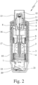
- Fig. 1 and 2 show a known atomizer 1 for atomizing a fluid 2, in particular a highly effective drug or the like, in a schematic representation in the untensioned state ( Fig. 1 ) and tensioned state ( Fig. 2 ).
- the atomizer 1 is designed in particular as a portable inhaler and preferably operates without propellant gas.
- a preferably respirable aerosol 14 ( Fig. 1 ) is formed, which can be inhaled or breathed in by a user or patient (not shown). Inhalation usually occurs at least once a day, especially several times a day, preferably at predetermined intervals, particularly depending on the patient's illness.
- the known atomizer 1 comprises a preferably insertable and in particular replaceable container 3 containing the fluid 2.
- the container 3 thus forms a reservoir for the fluid 2 to be atomized.
- the container 3 contains a sufficient quantity of fluid 2 or active ingredient for several doses of the fluid 2, for example, to be able to provide up to 200 dosage units (doses), thus enabling up to 200 atomizations or applications.
- the container 3 is preferably substantially cylindrical or cartridge-like and can be inserted into the atomizer 1 from below after opening it and can be replaced if necessary. It is preferably rigid, in particular with the fluid 2 being held in a collapsible bag 4 in the container 3.
- the atomizer 1 further comprises a conveying device, in particular a pressure generator 5, for conveying and atomizing the fluid 2, in particular in each case in a predetermined, possibly adjustable, dosage amount.
- a conveying device in particular a pressure generator 5, for conveying and atomizing the fluid 2, in particular in each case in a predetermined, possibly adjustable, dosage amount.
- the atomizer 1 or pressure generator 5 has in particular a holder 6 for the container 3, an associated drive spring 7, only partially shown, preferably with a locking element 8 that can be manually actuated for unlocking, a conveyor tube 9, preferably designed as a capillary, with an optional valve, in particular a check valve 10, a pressure chamber 11 and/or a discharge nozzle 12, in particular in the region of a mouthpiece 13.
- the container 3 is fixed in the atomizer 1 via the holder 6, in particular by clamping or locking, such that the delivery tube 9 is immersed in the container 3.
- the holder 6 can be designed such that the container 3 can be replaced.
- the fluid 2 in the pressure chamber 11 is pressurized by the conveyor tube 9 being moved upwards again by relaxing the drive spring 7, with the check valve 10 now closed, and now acting as a pressure piston.
- This pressure expels the fluid 2 through the discharge nozzle 12, where it is atomized into the preferably respirable aerosol 14, as shown in Fig. 1 indicated.
- the user or patient, not shown, can inhale the aerosol 14, wherein supply air can preferably be sucked into the mouthpiece 13 via at least one supply air opening 15.
- the atomizer 1 has in particular a housing upper part 16 and a rotatable inner part 17 ( Fig. 2 ) with an upper part 17a and a lower part 17b ( Fig. 1 ), wherein a housing part 18, in particular manually operable, is detachably fastened, in particular plugged, to the inner part 17, preferably by means of a holding element 19.
- the housing part 18 is detachable from the atomizer 1.
- the housing part 18 preferably forms a cap-like lower housing part and/or engages around or over a lower free end region of the container 3.
- the container 3 is preferably pierced or opened at the bottom.
- an axially acting spring 20 arranged in the housing part 18 comes into contact with the container bottom 21, which, with a piercing element 22, opens the container 3 or a bottom-side seal at the first installation for ventilation.
- the container 3 is moved back to its original position by the drive spring 7.
- the container 3 therefore performs a lifting movement during the clamping process and during the atomization process.
- the disclosure therein preferably relates to an atomizer with a spring pressure of 5 to 60 MPa, preferably 10 to 50 MPa on the fluid, with a fluid volume of 10 to 50 ⁇ l, preferably 10 to 20 ⁇ l, very preferably about 15 ⁇ l delivered per stroke.
- the fluid is converted into an aerosol whose droplets have an aerodynamic diameter of up to 20 ⁇ m, preferably 3 to 10 ⁇ m.
- the disclosure therein preferably relates to an atomizer with a cylindrical shape and a size of about 9 cm to about 15 cm in length and about 2 cm to about 5 cm in width, and with a nozzle jet fanning of 20° to 160°, preferably 80° to 100°.
- a nozzle jet fanning of 20° to 160°, preferably 80° to 100°.
- Fig. 3 and 4 show in schematic sections the proposed atomizer 1 according to a first embodiment.
- Fig. 3 shows the delivery condition with closed and especially sealed container 3.
- Fig. 4 shows the activated state, i.e. with container 3 already open.
- Fig. 3 and 4 show the atomizer 1 with an optional cover 23, in particular a cap-like cover, which covers or closes the mouthpiece 13 and in particular also the air supply openings 15 when the atomizer 1 is not in use.
- the cover 23 can be removed, opened, or otherwise removed or opened for use of the atomizer 1, for example.
- the (still) closed container 3 is already arranged in the atomizer 1 in the delivery state 1, as shown in Fig. 3 shown.
- a top-side, outer seal 24 of the container 3 and/or a septum 25 arranged inside the container 3, a membrane, a plastic closure, or the like is/are not yet opened.
- the container 3 may also have fewer and/or different opening options.
- the atomizer 1 is preferably designed such that the container 3 is or can be opened within the atomizer 1 before or upon first use of the atomizer 1. Opening of the container 3 occurs, in particular, when the seal 24 and the septum 25 or the like are open. This is also referred to here as the activated state.
- the piercing or opening of the ventilation opening 26 can occur separately, in particular only later upon (first) tensioning of the atomizer 1.
- the container 3 is opened in particular by a conveying element, in particular the conveying tube 9 or the like, preferably by piercing the container 3 or inserting it into the container 3.
- a conveying element in particular the conveying tube 9 or the like
- the conveying tube 9 pierces the seal 24 and is inserted through the septum 25 into the interior of the container 3, in particular into the bag 4, whereby the container 3 is opened, namely a fluid connection is formed for the outlet of the fluid 2 from the container 3.
- the container 3 is therefore opened in particular at the head end.
- the container 3 is then preferably moved together with the conveying element or conveying pipe 9 by means of the holder 6, whereby the established fluid connection is maintained, so that the container 3 preferably always remains open.
- the already mentioned, preferably bottom-side ventilation by opening the ventilation opening 26, can take place before, during or after the aforementioned, in particular head-side opening of the container 3, depending on the embodiment or requirement.
- the container 3 is pre-installed, and the housing part 18 is not fully axially pushed on in the delivery state. Rather, a securing part 27, for example, is arranged between the housing part 18 and the upper housing part 16, so that the housing part or lower part 18 is sufficiently spaced from the upper housing part 16 to be able to hold the (still) closed container 3 axially spaced from the conveyor pipe 9.
- the housing part 18 is in the non-activated, moved-away state preferably by at least one It is held captive and, in particular, non-detachably by a locking arm 28 or the like arranged on the upper housing part 16 or inner part 17.
- the locking arm 28 engages with a locking lug 29 in a locking recess 30 in the housing part 18, thereby positively securing the housing part 18 against complete axial removal.
- other design solutions are also possible.
- the housing part or lower part 18 of the atomizer 1 can no longer be detached from the atomizer 1 after the first (partial) axial sliding on, i.e. the atomizer 1 can no longer be opened, so that the container 3 cannot be replaced, in particular cannot be removed again.
- the security part 27 is, for example, essentially hollow-cylindrical and arranged axially between the housing part 18 and the upper housing part 16. In order to activate the atomizer 1, i.e., to push the housing part 18 fully axially open and thereby open the container 3, the security part 27 must first be removed or overcome.
- the security part 27 is designed in the manner of a banderol or the like, for example made of plastic, and can be manually opened, removed, overcome, broken, cut, or destroyed.
- the security part 27 can alternatively or simultaneously form or represent a tamper-evident closure.
- other designs of the security part 27 are also possible, for example in the form of a security tab or the like.
- any other suitable security device can be used instead of the security part 27.
- the housing part 18 must first be rotated slightly in order to then be (fully) pushed axially open. Possible implementations of the security device are described in particular in the WO 2006/125577 A1 revealed.
- a user can completely slide the housing part 18 open in the axial direction and thereby bring about the activated state of the atomizer 1, namely open the container 3 by inserting the conveying element or conveying tube 9.
- Fig. 4 shows this activated state with the housing part 18 completely pushed on.
- the housing part 18 is preferably secured or held in a form-fitting manner, in particular by engagement of the locking arm 28 or the locking lug 29 in a corresponding, further locking recess 31 or by another mechanical securing means.
- Fig. 4 shows the atomizer 1 or the container 3 in the activated state, the container 3 is already open and the housing part 18 is fully pushed on axially.
- the holder 6, together with the conveyor tube 9 is moved axially towards or into the housing part 18, whereby the holder 6 is brought into engagement with the container 3 and preferably also the container 3 is pressed against the piercing element 22 in the region of the bottom of the housing part 18, thereby piercing or opening the ventilation opening 26.
- Fig. 4 shows the atomizer 1 in the relaxed state, i.e., specifically after the first atomization.
- the holder 6 is engaged with the container 3, and the delivery tube 9 is fully inserted into the container 3.
- the atomizer 1 can be stored in the delivery state shown, i.e. with the container 3 (still) closed.
- the closed seal 24 ensures that any solvent contained in the fluid 2 cannot escape, or at most only to a very small extent.
- the atomizer 1 preferably has a transport lock (not shown).
- the transport lock prevents, for example, by friction, force, or form locking, the container 3 from moving axially in an undesired manner within the atomizer 1—for example, during transport, if the atomizer 1 accidentally falls down, or the like—and thus from opening unintentionally.
- opening of the container 3 is preferably carried out exclusively by mechanical action and/or manual operation. However, additionally or alternatively, opening by other means, for example chemically, electrically, magnetically, pneumatically, hydraulically, or the like, is also possible.
- the proposed atomizer 1 is activated after the container 3 or housing part 18 has been fully pushed on axially and is operated according to the Fig. 1 and 2 shown atomizer 1 can be used.
- the proposed atomizer 1 is preferably designed to be portable, in particular it is a mobile handheld device.
- the proposed atomizer operates purely mechanically.
- the atomizer 1 can, in principle, also operate in any other manner.
- the term "conveying device” or “pressure generator” should be understood very broadly.
- the pressure required for dispensing and atomization can also be generated by propellant gas, a pump, or any other suitable means.
- the proposed nebulizer 1 is designed in particular for the short-term nebulization of the fluid 2, for example, for one or two breaths. However, it can also be designed or used for longer or continuous nebulization.
- the atomizer 1 preferably has a protective device 32 to prevent or at least reduce possible contamination of the fluid 2.
- the protective device 32 has a germ-proof, in particular sterile covering, preferably a bag 33, for receiving the atomizer 1 and preferably also the container 3 in the delivery state, as shown in Fig. 3
- the envelope or bag 33 is preferably made of film or plastic material and/or is at least partially transparent.
- the envelope or bag 33 is preferably gas-tight.
- the envelope or bag 33 preferably surrounds the atomizer 1 relatively loosely and/or is in particular flexible or elastic, so that the atomizer or container 3 can preferably be activated while the envelope is still closed.
- the casing After activation, the casing can be opened, especially torn or cut, and removed so that the atomizer can then be used normally.
- Fig. 4 bag 33 has already been removed.
- the protective device 32 or the covering ensures, in particular, that the atomizer 1 and the container 3 can be stored germ-tight and, in particular, sterile for a very long time.
- the already sterile container 3 is inserted into the sterile nebulizer 1 under sterile conditions, and the nebulizer 1 is then enclosed or enclosed under sterile conditions by the likewise sterile wrapping. Subsequent or additional sterilization is then no longer necessary, but is possible.
- sterilization takes place only after the container 3 has been inserted into the nebulizer 1 and, if necessary, even only after the nebulizer 1 is enclosed by the sheath.
- the nebulizer 1, container 3, and/or the sheath do not have to be sterilized in advance and/or do not have to be operated under sterile conditions.
- Sterilization can be achieved, in particular, by radiation (e.g., microwave, UV, X-ray, or gamma radiation) and/or gas (e.g., ethylene oxide). If necessary, it may also be sufficient to fill the packaging with a sterilizing gas during sealing.
- radiation e.g., microwave, UV, X-ray, or gamma radiation
- gas e.g., ethylene oxide
- the protective device 32 can alternatively or additionally have a germ-tight receiving space 34 for the container 3 in the atomizer 1.
- the receiving space 34 is formed by the atomizer 1, particularly preferably by the housing part 18, which in this case can then be attached in a germ-tight manner.
- other design solutions are also possible here.
- Sterilization then takes place, as with the bag 33, preferably before, during and/or after closing.
- the protective device 32 can have a contact section 35 for the fluid 2 that kills bacteria or other germs or has an antibacterial effect.
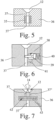
- the contact section 35 is in Fig. 5 which shows a schematic, enlarged section of a part of the atomizer 1, in particular an outlet or nozzle assembly 36.
- the contact section 35 acts in particular oligodynamically.
- the contact section 35 contains or is made of silver and/or copper, such alloys, mixtures, or the like.
- the contact section 35 can also contain or be made of activated carbon.
- the contact section 35 is preferably arranged in or formed from a section of the fluid path, in particular in the outlet or nozzle assembly 36, in an outlet channel 37 or in the conveying device or the pressure generator 5 or in or on the container 3.
- the contact section 35 is arranged near the discharge nozzle 12 or another outlet and/or downstream of the pressure chamber 11.
- the contact section 35 can alternatively or additionally also be arranged in the pressure chamber 11. Alternatively or additionally, the contact section 35 can also be arranged on the container 3, in particular at its outlet and/or on or in the conveyor pipe 9 or the like.
- the contact section 35 can also be arranged at other suitable locations. If necessary, multiple contact sections 35 can also be provided along the fluid path.
- the contact section 35 forms, in particular, part of a wall of a channel, such as the outlet channel 37.
- the contact section 35 is, in particular, hollow-cylindrical or provided with a corresponding bore, opening, or the like.
- other design solutions are also possible.
- the contact section 35 it is also possible for the contact section 35 to form a flat side or opposing flat sides of a very flat channel section in order to achieve the largest possible contact area between the contact section 35 on the one hand and the fluid 2 on the other.
- the contact section 35 can generally be formed by a component or a section of a component of the atomizer 1 or by a coating at least in some areas.
- the contact section 35 can also be formed by a material admixture and/or in particular discrete particles or other, in particular oligodynamically or antibacterially acting particles, or such particles can be integrated into a material (for example metal, composite material, plastic or ceramic). so that the particles can interact with the fluid 2.
- the particles can also be arranged in a surface area or form a coating.
- the conveying element or conveying pipe 9 is made of and/or coated with a corresponding antibacterial material, such as a silver-containing alloy.
- plastic surfaces can also be coated accordingly to form the contact section 35.
- the contact section 35 is formed on or in the discharge nozzle 12 or outlet or nozzle assembly 36.
- the contact section 35 is formed or arranged in a residual drop area on the outside of the nozzle 12 or outlet or nozzle assembly 36.
- the contact section 35 can also be integrated into or formed by a filter.
- all metal components of the atomizer 1 that come into contact with the fluid 2 are made of and/or coated with at least substantially the same material and/or material having at least substantially the same electronegativity.
- the outlet or nozzle assembly 36 preferably has the outlet channel 37 with the adjoining discharge nozzle 12. Particularly preferably, the outlet or nozzle assembly 36 is manufactured in one piece—optionally with the exception of the contact section 35—particularly preferably from ceramic, sintered material, silicon, glass, or the like.
- the outlet or nozzle assembly 36 is preferably fluidically connected to the pressure chamber 11 on the inlet side. It is installed, in particular, within the mouthpiece 13 in such a way that, upon fluid discharge, the desired atomization of the fluid 2 as an aerosol 14 occurs in and/or out of the mouthpiece 13.
- the cover 23 can also be designed as a protective device 32.
- the cover 23 is preferably designed to be germ-tight in order to prevent or at least reduce possible contamination of the fluid 2 via the discharge nozzle 12.
- the cover 23 can also be placed directly on the discharge nozzle 12 or the outlet or nozzle assembly 36.
- the cover 23, particularly in this area, or the outlet or nozzle assembly 36 in this area can be designed to be oligodynamic, or can have or form a contact section 35 there in the sense already mentioned.
- Fig. 6 shows in a Fig. 5 corresponding illustration shows a schematic section, also not to scale, of the outlet or nozzle assembly 36 of the atomizer 1 according to the second embodiment.
- the protective device 32 in addition to or alternatively to the possibilities already described, has a lockable valve 38 for preventing or at least minimizing contamination of the fluid 2 in the container 3, in the conveying element, such as the conveying pipe 9, in the pressure chamber 11, in the outlet channel 37 and/or in another fluid-conducting section or generally in the conveying device or the pressure generator 5.
- the valve 38 blocks, in particular, an associated channel, such as the outlet channel 37, in order to prevent or at least minimize the penetration of germs.
- valve 38 is assigned to the outlet or nozzle assembly 36, specifically, it is installed therein.
- other design solutions are also possible.
- the valve 38 is preferably designed to close automatically, in particular by spring force.
- a movable valve element 39 is moved by means of a closing spring 40 into the Fig. 6 shown closed position, in which it blocks the outlet channel 37.
- the valve 38 is preferably openable by the applied fluid pressure.
- a connecting channel 41 is provided for this purpose, branching off from the outlet channel 37 upstream of the valve 38, so that the valve element 39 can be opened against the force of the closing spring 40 when the appropriate fluid pressure is present.
- other design solutions are also possible.
- valve 38 can be designed as a one-way or check valve.
- valve 38 preferably operates exclusively mechanically or hydraulically.
- valve 38 can also operate electrically, electromagnetically, piezoelectrically, pneumatically, or in any other suitable manner, and in particular, can be opened and/or closed.
- the valve 38 is preferably designed to block the outlet channel 37 or another channel section for guiding the fluid 2.
- it may also be sufficient to interrupt the fluid flow or the fluid column, for example by means of a corresponding capillary stop or the like, so that, for example, two separate fluid regions or columns are formed that are not in direct fluidic contact with one another, whereby the transmission of germs between them is correspondingly prevented or at least made more difficult.
- valve 38 can be arranged at various locations.
- the valve 38 is arranged directly adjacent to or upstream of the discharge nozzle 12 and/or downstream of the pressure chamber 11.
- the valve 38 can also be arranged on the container 3, in particular to block its outlet.
- the contact section 35 can also be integrated into the valve 38 or vice versa.
- a filter 42 is provided as the protective device 32, in addition to or as an alternative to the previously described possibilities.
- the filter has only such fine passages 43 that it is at least substantially germ-tight. Germs, such as bacteria or the like, are therefore at least largely unable to pass through the passages 43.
- the filter 42 is preferably arranged in the outlet channel 37 or another channel section, so that the fluid 2 must first necessarily pass through the filter 42, particularly immediately before being discharged via the discharge nozzle 12 or another outlet.
- the filter 42 can then—corresponding to the contact section 35 or valve 38—prevent or at least minimize unwanted penetration of germs on the outlet side or nozzle side.
- the filter 42 is arranged downstream of the pressure chamber 11 or conveying device or a pump or the pressure generator 5 and/or upstream of the discharge nozzle 12.
- the atomizer 1 can also have several discharge nozzles 12, as in Fig. 7 shown as an example.
- the discharge nozzles 12 are then connected either via a common channel or - as shown - via separate outlet channels 37' and 37", here in particular to the filter 42.
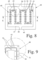
- Fig. 8 to 12 show a proposed filter 42, which can be used in particular as a protective device 32 in the proposed nebulizer 1—particularly preferably in the third embodiment, in particular integrated into the outlet or nozzle assembly 36—or in other nebulizers 1, inhalers, or the like.
- the filter 42 is intended or usable in particular to prevent or at least minimize the possible contamination of a fluid 2 that is preferably to be nebulized.
- the fluid 2 can also be dispensed in any other suitable manner.
- Fig. 8 shows the open filter 42 in a plan view.
- Fig. 9 shows an enlarged section of Fig. 8 .
- Fig. 10 shows the closed filter 42 in a schematic section along the line XX of Fig. 8 .
- Fig. 11 shows an enlarged section of Fig. 10.
- Fig. 12 shows a perspective view of a section of the filter 42 with uncovered passages 43.
- the filter 42 has only such fine passages 43 that it is at least essentially germ-tight.
- the average or largest diameter d ( Fig. 12 ) or a largest cross-sectional extent of the passages 43 is about 0.3 ⁇ m or less.
- the passages 43 are preferably substantially rectangular in cross-section.
- the maximum or average width b and/or the maximum or average height h and/or the maximum diameter d of the passages 43 is at most 0.3 ⁇ m or less.
- the widths b and the height h are each substantially 0.2 ⁇ m.
- the passages 43 are preferably each longer than their maximum diameter d. This contributes to high stability and, in particular, high pressure resistance of the filter 42. In particular, their length 1 is approximately 1 ⁇ m to 5 ⁇ m.
- the filter 42 is preferably constructed from a piece of material 44 and a cover element 45.
- Fig. 8 shows the filter 42 or the material piece 44 in plan view without the cover element 45.
- the section according to Fig. 10 shows the filter 42 or the piece of material 44 with the cover element 45.
- the passages 43 are cut out starting from a flat side of the piece of material 44, as can be seen in particular in Fig. 10 indicated.
- the passages 43 are formed between the material piece 44 and the cover element 45.
- other structural solutions are also possible.
- the piece of material 44 is cut out starting from a flat side and structured as desired, in particular by etching, for example, as known from semiconductor technology, by embossing, by laser processing, and/or by any other suitable processing method. For example, larger areas can also be milled away. Machining accuracy is essential, as very fine, defined openings 43 are formed.
- the passages 43 are preferably located essentially in a plane that runs parallel to the flow through the passages 43.
- the passages 43 are preferably laterally limited or covered by a common cover, namely the cover element 45.
- the passages 43 are preferably arranged next to one another in a line and in particular run in a meandering manner ( Fig. 8 ) or zigzag or in any other suitable manner.
- the filter 42 preferably has an inlet 46 and an adjoining distribution chamber 47.
- a filter structure 48 with the passages 43 separates the distribution chamber 47 from a collection chamber 49 located on the other side of the filter structure 48, which is connected to an outlet 50 of the filter 42.
- the inlet 46 is preferably connected to the pressure chamber 11 or the outlet channel 37.
- the outlet 50 is preferably connected to the outlet channel 37 or the discharge nozzle 12.
- the filter 42 is connected in such a way that the Fig. 8 to 12 Fluid 2 (not shown) must necessarily pass through the filter 42 during discharge, i.e. must necessarily flow through the passages 43.
- the passages 43, the inlet 46, the distribution chamber 47, the collection chamber 49 and/or the outlet 50 are preferably formed as depressions in the piece of material 44 and are in particular surrounded by a remaining edge of the piece of material 44, via which the connection to the cover element 45 is made.
- the filter structure 48 extends in particular essentially in a meandering, zigzag, linear or any other suitable manner, particularly preferably in such a way that as many passages 43 as possible can be formed.
- the filter 42 has, for example, more than 1,000 passages 43 with a relatively small total volume and, in particular, a very small absorption volume of fluid 2 (preferably about 1 ⁇ l or less).
- the large number of passages 43 connected in parallel results in a comparatively or at least sufficiently low flow resistance.
- the filter structure 48 initially has a preferably rib-like or web-like elevation 51 that rises from the bottom of the distribution chamber 47 or collection chamber 49 toward the cover element 45.
- the elevation 51 has, for example, a width B of a few ⁇ m, approximately 5 ⁇ m in the illustrated example.
- the elevation 51 is, in particular, continuous, and/or linear and runs, in particular, in a meandering, zigzag, linear, or similar manner, corresponding to the filter structure 48.
- a preferably narrower, in particular web-, rib-, or strip-like elevation 52 which runs along the elevation 51 and has, for example, a width reduced to approximately 5 to 50% compared to the elevation 51.
- the height and width of the elevation 52 are, for example, each approximately 1 ⁇ m. Depending on the desired length of the passages 43, the width can also be, for example, up to 5 ⁇ m. The same applies to the height for the possible variation of the depth or cross-section of the passages 43.
- the passages 43 are formed in particular by grooves or groove-like recesses or depressions in the elevation 52.
- the center-to-center distance of the passages 43 is, for example, approximately 1 ⁇ m or the width or thickness of the elevation 52. However, other dimensions are also possible.
- optional support structures 53 can be provided, as in Fig. 8
- the support structures 53 extend from the elevation 51 next to the elevation 52 to the cover element 45, to which they are preferably also connectable.
- the optional support structures 53 are not shown for simplification reasons.
- Solid material or plate material is preferably used as the starting material for the material piece 44.
- the piece of material 44 preferably consists of silicon or another suitable material, for example, sintered material, ceramic, glass, or the like.
- the cover element 45 consists in particular of the same material or another suitable material, preferably glass.
- the connection of the piece of material 44 and the cover element 45 to one another is achieved in particular by so-called bonding or welding.
- any other suitable type of connection or a sandwich construction or the like is also possible here.
- the cover element 45 is produced from a plate piece that is divided or separated into a plurality of cover elements 45.
- a silicon wafer is particularly preferably used as the plate piece, as already explained.
- a silicon wafer or another wafer, a glass pane, or the like can also be used for the plate piece for producing the cover elements 45.
- a plate piece is used for both the production of the material pieces 44 and the production of the cover elements 45, it is particularly preferred to connect the plate pieces to one another before disassembling them into the individual material pieces 44 or cover element 45. This significantly simplifies assembly and positioning.
- the filter 42 can also have several—i.e., two or more—rows of passages 43 arranged one behind the other.
- the rows can, for example, run parallel to one another.
- several—i.e., two or more—elevations 52 can be provided on a raised portion 51—in particular running parallel and/or spaced from one another.
- several—in particular, two or more—elevations 51 can each be arranged with at least one raised portion 52 one behind the other or in series—in particular running parallel and/or spaced from one another.
- the filter 42 can also be combined with another filter, such as a pre-filter or the like, i.e. in particular connected in series.
- another filter such as a pre-filter or the like, i.e. in particular connected in series.
- the proposed filter 42 can also be used for the outlet or nozzle assembly 36 - for example according to the third embodiment according to Fig. 7 - can be used.
- the filter 42 is designed as a structural unit with the discharge nozzle 12 or the outlet or nozzle assembly 36. This significantly simplifies manufacture and assembly.
- the discharge nozzle 12, or possibly several discharge nozzles 12 is then manufactured together with the associated filter 42, most preferably in the manner described above from the piece of material 44 and the cover element 45, or in any other suitable manner.
- the proposed solution can be used not only with the nebulizers 1 described in detail here, but also with other nebulizers or inhalers, related containers 3 or the like.
- the proposed filter 42 can also be used for other purposes, for example, in the purification of the fluid 2, generally in the separation of germs, bacteria, cells, or the like.
- the filter 42 is suitable and designed for small or very small quantities in the ⁇ l range.
- the atomizer 1 may also have another filter 42, for example made of porous material, in order to protect the discharge nozzle 12 or the outlet or nozzle assembly 36 or the outlet channel 37 from possible clogging.
- another filter 42 for example made of porous material
- the fluid 2 preferably contains ethanol and in particular contains ethanol as a solvent.
- the fluid 2 may contain EDTA (ethylenediaminetetraacetic acid) or its salts as complexing agents.
- EDTA ethylenediaminetetraacetic acid
- the fluid 2 is a liquid, as already mentioned, in particular an aqueous, ethanolic, or aqueous/ethanolic pharmaceutical preparation.
- aqueous, ethanolic, or aqueous/ethanolic pharmaceutical preparation may also be another pharmaceutical preparation, a suspension, or the like.
- compounds are preferably used which are selected from the group consisting of tiotropium salts, preferably the bromide salt, oxitropium salts, preferably the bromide salt, flutropium salts, preferably the bromide salt, ipratropium salts, preferably the bromide salt, glycopyrronium salts, preferably the bromide salt, trospium salts, preferably the chloride salt, tolterodine.
- the cations represent the pharmacologically active components.
- the above-mentioned salts can preferably contain chloride, bromide, iodide, sulfate, phosphate, methanesulfonate, nitrate, maleate, acetate, citrate, fumarate, Tartrate, oxalate, succinate, benzoate, or p-toluenesulfonate, with chloride, bromide, iodide, sulfate, methanesulfonate, or p-toluenesulfonate being preferred as counterions.
- the chlorides, bromides, iodides, and methanesulfonates are particularly preferred.
- X - is a singly negatively charged anion, preferably an anion selected from the group consisting of fluoride, chloride, bromide, iodide, sulfate, phosphate, methanesulfonate, nitrate, maleate, acetate, citrate, fumarate, tartrate, oxalate, succinate, benzoate and p-toluenesulfonate, preferably a singly negatively charged anion, particularly preferably an anion selected from the group consisting of fluoride, chloride, bromide, methanesulfonate and p-toluenesulfonate, especially preferably bromide, optionally in the form of their racemates, enantiomers or hydrates.
- X - is a singly negatively charged anion, preferably an anion selected from the group consisting of fluoride, chloride, bromide, iodide, sulfate, phosphate, methane
- the acid addition salts of the betamimetics are preferably selected from the group consisting of hydrochloride, hydrobromide, hydroiodide, hydrosulfate, hydrophosphate, hydromethanesulfonate, hydronitrate, hydromaleate, hydroacetate, hydrocitrate, hydrofumarate, hydrotartrate, hydrooxalate, hydrosuccinate, hydrobenzoate and hydro-p-toluenesulfonate.
- Dopamine agonists used are preferably compounds selected from the group consisting of bromocriptine, cabergoline, alpha-dihydroergocryptine, lisuride, pergolide, pramipexole, roxindole, ropinirole, talipexole, terguride and viozan, optionally in the form of their racemates, enantiomers, diastereomers and optionally in the form of their pharmacologically acceptable acid addition salts, solvates, or hydrates.
- the acid addition salts of the betamimetics are preferably selected from the group consisting of hydrochloride, hydrobromide, hydroiodide, hydrosulfate, hydrophosphate, hydromethanesulfonate, hydronitrate, hydromaleate, hydroacetate, hydrocitrate, hydrofumarate, hydrotartrate, hydrooxalate, hydrosuccinate, hydrobenzoate, and hydro-p-toluenesulfonate.
- H1 antihistamines compounds are preferably used which are selected from the group consisting of epinastine, cetirizine, azelastine, fexofenadine, levocabastine, loratadine, mizolastine, ketotifen, emedastine, dimetindene, clemastine, bamipine, cexchlorpheniramine, pheniramine, doxylamine, chlorphenoxamine, dimenhydrinate, diphenhydramine, promethazine, ebastine, desloratidine and meclozine, optionally in the form of their racemates, enantiomers, diastereomers and optionally in the form of their pharmacologically acceptable acid addition salts, solvates or hydrates.
- the acid addition salts of the betamimetics are preferably selected from the group consisting of hydrochloride, hydrobromide, hydroiodide, hydrosulfate, hydrophosphate, hydromethanesulfonate, hydronitrate, hydromaleate, hydroacetate, hydrocitrate, hydrofumarate, hydrotartrate, hydrooxalate, hydrosuccinate, hydrobenzoate and hydro-p-toluenesulfonate.
- inhalable macromolecules can be used, as in EP 1 003 478 A1 or CA 2297174 A1 revealed.
- the compound may originate from the group of derivatives of ergot alkaloids, triptans, CGRP inhibitors, phosphodiesterase V inhibitors, optionally in the form of their racemates, enantiomers or diastereomers, optionally in the form of their pharmacologically acceptable acid addition salts, their solvates and/or hydrates.
Landscapes
- Life Sciences & Earth Sciences (AREA)
- Engineering & Computer Science (AREA)
- Health & Medical Sciences (AREA)
- Chemical & Material Sciences (AREA)
- Chemical Kinetics & Catalysis (AREA)
- Geology (AREA)
- Ceramic Engineering (AREA)
- Veterinary Medicine (AREA)
- Animal Behavior & Ethology (AREA)
- General Health & Medical Sciences (AREA)
- Public Health (AREA)
- Biomedical Technology (AREA)
- Heart & Thoracic Surgery (AREA)
- Anesthesiology (AREA)
- Hematology (AREA)
- Inorganic Chemistry (AREA)
- Epidemiology (AREA)
- Mechanical Engineering (AREA)
- Biophysics (AREA)
- Bioinformatics & Cheminformatics (AREA)
- Pulmonology (AREA)
- Containers And Packaging Bodies Having A Special Means To Remove Contents (AREA)
- Medicinal Preparation (AREA)
Claims (13)
- Pulvérisateur (1) se présentant sous la forme d'un inhalateur pour la thérapie médicale par aérosol, servant à pulvériser un fluide (2),dans lequel le pulvérisateur (1) présente un contenant (3) avec le fluide (2),une buse de distribution (12) servant à pulvériser le fluide (2) etun générateur de pression (5) en tant que dispositif de refoulement servant à refouler et à pulvériser le fluide (2) avec une fixation (6) pour le contenant (3), un tube de refoulement (9) et un ressort d'entraînement (7),dans lequel le générateur de pression (5) présente une chambre de pression (11) servant à générer une pression de ressort de 5 à 60 MPa sur le fluide (2),le contenant (3) peut être déplacé selon une course pendant le refoulement de fluide, la génération de pression et la pulvérisation, etun volume de fluide de 10 à 50 µl est distribué par course lors de la pulvérisation,caractérisé en ceque le pulvérisateur (1) présente des dispositifs de protection (32) servant à empêcher une contamination du fluide (2) et les dispositifs de protection (32) comprennent un filtre (42) au moins largement étanche aux germes et une soupape (38) pouvant être bloquée servant à bloquer un tronçon de canal servant à acheminer le fluide,dans lequel le filtre et la soupape (38) sont disposés en aval de la chambre de pression (11), etdans lequel le filtre (42) a des ouvertures (43) si fines qu'il est au moins substantiellement imperméable aux germes, la largeur maximale (b), la hauteur maximale (h) et/ou le diamètre maximal (d) des ouvertures (43) étant d'environ 0,3 nm ou moins.
- Pulvérisateur selon la revendication 1, caractérisé en ce que la soupape (38) est disposée directement de manière adjacente ou en amont de la buse de distribution (12).
- Pulvérisateur selon la revendication 1, caractérisé en ce que la buse de distribution (12) fait partie d'un module de buses (36), qui présente un canal d'évacuation (37) avec la buse de distribution (12) s'y raccordant, et que la soupape (38) bloque le canal d'évacuation (37).
- Pulvérisateur selon l'une quelconque des revendications 1 à 3, caractérisé en ce que le contenant (3) contient plusieurs doses du fluide (2) dans l'état de délivrance.
- Pulvérisateur selon la revendication 4, caractérisé en ce que le fluide (2) est exempt d'agent de conservation.
- Pulvérisateur selon la revendication 4 ou 5, caractérisé en ce que le contenant (3) est déjà inséré dans le pulvérisateur (1) dans l'état de délivrance, mais en particulier est encore fermé de manière étanche aux germes.
- Pulvérisateur selon l'une quelconque des revendications 4 à 6, caractérisé en ce que déjà dans l'état de délivrance du pulvérisateur (1), le contenant (3) fermé est disposé dans le pulvérisateur (1), et le pulvérisateur (1) est réalisé de telle manière que le contenant (3) est ouvert avant ou lors de l'utilisation pour la première fois du pulvérisateur (1) à l'intérieur du pulvérisateur (1).
- Pulvérisateur selon l'une quelconque des revendications 4 à 7, caractérisé en ce que le pulvérisateur (1) est réalisé de telle manière que le contenant (3) n'est pas remplaçable, en particulier ne peut être retiré.
- Pulvérisateur selon l'une quelconque des revendications précédentes, caractérisé en ce que la soupape (38) se ferme de manière autonome, de préférence par la force de ressort.
- Pulvérisateur selon la revendication 9, caractérisé en ce que la soupape (38) peut être ouverte par une pression de fluide présente.
- Pulvérisateur selon l'une quelconque des revendications précédentes, caractérisé en ce que le filtre (42) présente des passages (43), qui sont fabriqués par gravure, estampage et/ou usinage laser.
- Pulvérisateur selon l'une quelconque des revendications précédentes, caractérisé en ce que le filtre (42) est fabriqué à partir d'un matériau de frittage, de céramique, de verre et/ou de silicium.
- Pulvérisateur selon l'une quelconque des revendications précédentes, caractérisé en ce que le filtre (42) forme une unité modulaire avec la buse de distribution (12).
Applications Claiming Priority (2)
| Application Number | Priority Date | Filing Date | Title |
|---|---|---|---|
| DE102007023012.7A DE102007023012B4 (de) | 2007-05-15 | 2007-05-15 | Zerstäuber |
| PCT/EP2008/055863 WO2008138936A2 (fr) | 2007-05-15 | 2008-05-13 | Pulvérisateur et filtre |
Publications (3)
| Publication Number | Publication Date |
|---|---|
| EP2152341A2 EP2152341A2 (fr) | 2010-02-17 |
| EP2152341B1 EP2152341B1 (fr) | 2019-12-11 |
| EP2152341B2 true EP2152341B2 (fr) | 2025-04-02 |
Family
ID=39711887
Family Applications (1)
| Application Number | Title | Priority Date | Filing Date |
|---|---|---|---|
| EP08759561.7A Active EP2152341B2 (fr) | 2007-05-15 | 2008-05-13 | Pulvérisateur sous forme d'un inhalateur pour aérosolthérapie |
Country Status (5)
| Country | Link |
|---|---|
| US (1) | US20110005517A1 (fr) |
| EP (1) | EP2152341B2 (fr) |
| JP (2) | JP2010526620A (fr) |
| DE (1) | DE102007023012B4 (fr) |
| WO (1) | WO2008138936A2 (fr) |
Families Citing this family (36)
| Publication number | Priority date | Publication date | Assignee | Title |
|---|---|---|---|---|
| EP2077132A1 (fr) | 2008-01-02 | 2009-07-08 | Boehringer Ingelheim Pharma GmbH & Co. KG | Dispositif distributeur, dispositif de stockage et procédé pour la distribution d'une formulation |
| US8109414B2 (en) * | 2008-10-07 | 2012-02-07 | Ing. Erich Pfeiffer Gmbh | Discharge device |
| EP2414560B1 (fr) | 2009-03-31 | 2013-10-23 | Boehringer Ingelheim International GmbH | Procédé de revêtement d'une surface d'un composant |
| EP2432531B1 (fr) | 2009-05-18 | 2019-03-06 | Boehringer Ingelheim International GmbH | Adaptateur, dispositif d'inhalation et pulvérisateur |
| WO2011064163A1 (fr) | 2009-11-25 | 2011-06-03 | Boehringer Ingelheim International Gmbh | Nébuliseur |
| MX2012005961A (es) | 2009-11-25 | 2012-06-14 | Boehringer Ingelheim Int | Nebulizador. |
| UA107096C2 (xx) * | 2009-11-25 | 2014-11-25 | Розпилювач | |
| US10016568B2 (en) | 2009-11-25 | 2018-07-10 | Boehringer Ingelheim International Gmbh | Nebulizer |
| EP2585151B1 (fr) | 2010-06-24 | 2018-04-04 | Boehringer Ingelheim International GmbH | Nébuliseur |
| EP2593164B1 (fr) | 2010-07-16 | 2017-03-22 | Boehringer Ingelheim International GmbH | Système de filtre conçu pour être utilisé dans des appareils médicaux |
| WO2012130757A1 (fr) | 2011-04-01 | 2012-10-04 | Boehringer Ingelheim International Gmbh | Appareil médical pourvu d'un récipient |
| US9827384B2 (en) | 2011-05-23 | 2017-11-28 | Boehringer Ingelheim International Gmbh | Nebulizer |
| DK2526989T3 (da) * | 2011-05-23 | 2020-04-06 | Boehringer Ingelheim Int | System omfattende en forstøver |
| CA2884836C (fr) | 2011-09-14 | 2018-01-23 | Brian Anthony LEMPER | Systemes d'inhalation, appareils respiratoires et methodes |
| FR2982850B1 (fr) * | 2011-11-17 | 2015-07-24 | Rexam Dispensing Sys | Tete de distribution pour un systeme de distribution d’un produit sous pression |
| WO2013152894A1 (fr) | 2012-04-13 | 2013-10-17 | Boehringer Ingelheim International Gmbh | Pulvérisateur comprenant des moyens de détrompage |
| RU2644257C2 (ru) | 2012-07-26 | 2018-02-08 | Аллерган, Инк. | Система упаковки/укупорки с двумя крышками для сохранения стерильности дозирующего наконечника во время хранения |
| US9396502B2 (en) * | 2013-01-23 | 2016-07-19 | Facebook, Inc. | Enabling delayed interactions with content items presented by a social networking system |
| NL2010405C2 (en) | 2013-03-07 | 2014-09-10 | Medspray Xmems Bv | Aerosol generator for generating an inhalation aerosol. |
| JP6643231B2 (ja) | 2013-08-09 | 2020-02-12 | ベーリンガー インゲルハイム インターナショナル ゲゼルシャフト ミット ベシュレンクテル ハフツング | ネブライザ |
| EP2835146B1 (fr) | 2013-08-09 | 2020-09-30 | Boehringer Ingelheim International GmbH | Atomiseur |
| CA2922993A1 (fr) * | 2013-09-11 | 2015-03-19 | Bixa Research And Health Inc. | Pulverisateur intranasal jetable |
| CA2948071C (fr) | 2014-05-07 | 2022-08-30 | Boehringer Ingelheim International Gmbh | Contenant, nebuliseur et utilisation |
| HUE058904T2 (hu) | 2014-05-07 | 2022-09-28 | Boehringer Ingelheim Int | Porlasztókészülék |
| US10722666B2 (en) | 2014-05-07 | 2020-07-28 | Boehringer Ingelheim International Gmbh | Nebulizer with axially movable and lockable container and indicator |
| EP3307365A1 (fr) | 2015-06-15 | 2018-04-18 | The Technology Partnership PLC | Ensemble de micro-buses avec filtre |
| CN108602080B (zh) * | 2015-12-04 | 2022-06-24 | 美德斯普瑞公司 | 流体喷雾器 |
| EP3202709B1 (fr) | 2016-02-04 | 2019-04-10 | Boehringer Ingelheim microParts GmbH | Outil de moulage ayant un support magnétique |
| RU2761367C2 (ru) | 2016-09-15 | 2021-12-07 | Софтхейл Нв | Клапан, в частности для устройства для введения жидкого лекарственного средства, и соответствующее устройство для введения жидкого лекарственного средства |
| DE202017005165U1 (de) * | 2017-10-06 | 2017-11-23 | WERRTA GmbH Düsen- und Zerstäubungstechnik | Düsenkörper |
| EP3563894B1 (fr) | 2018-05-04 | 2021-12-22 | Boehringer Ingelheim International GmbH | Nébuliseur et récipient |
| CN109570788A (zh) * | 2019-01-22 | 2019-04-05 | 广东天劲新能源科技股份有限公司 | 电池自动上下料激光焊接机 |
| CN110215401B (zh) * | 2019-07-08 | 2021-08-03 | 刘海霞 | 一种多功能医疗儿科护理用喂药装置 |
| CN110711299A (zh) * | 2019-10-22 | 2020-01-21 | 周莹 | 一种呼吸内科用雾化吸入系统 |
| EP4041654B1 (fr) * | 2019-11-07 | 2025-08-27 | 623 Medical, LLC | Dispositif vaporéfrigérant |
| IT202000027618A1 (it) * | 2020-11-18 | 2022-05-18 | Lumson Spa | Dispositivo di erogazione di una sostanza fluida |
Family Cites Families (44)
| Publication number | Priority date | Publication date | Assignee | Title |
|---|---|---|---|---|
| GB414953A (en) * | 1932-12-24 | 1934-08-16 | Josef Schoene | Medical injection syringe |
| US2651303A (en) * | 1948-11-13 | 1953-09-08 | Richard S Johnson | Inhaler |
| US3440144A (en) * | 1965-05-21 | 1969-04-22 | Andersen Prod H W | Method and apparatus for checking and testing the effectiveness of sterilization |
| US4126559A (en) * | 1976-03-30 | 1978-11-21 | Pall Corporation | Pharmaceutical filter |
| JPS6274364A (ja) * | 1985-09-27 | 1987-04-06 | 株式会社 ニツシヨ− | 医療用具 |
| US4653494A (en) * | 1985-12-20 | 1987-03-31 | Ruderian Max J | Nasal inhalation system |
| US4805377A (en) * | 1987-12-23 | 1989-02-21 | Entravision, Inc. | Method of packaging and sterilizing a pharmaceutical product |
| SG45171A1 (en) | 1990-03-21 | 1998-01-16 | Boehringer Ingelheim Int | Atomising devices and methods |
| DE4027320C2 (de) * | 1990-08-29 | 1993-09-30 | Ursapharm Arzneimittel Gmbh | Fluid-Abgabeeinrichtung für keimfreies Fluid |
| DE69117193T2 (de) | 1990-12-04 | 1996-06-27 | Dmw (Technology) Ltd., Suffolk | Düsenvorrichtung zum verhindern des rückflusses |
| AU3253293A (en) * | 1992-01-21 | 1993-08-03 | Gabriel Meyer | Device for storing a liquid medicinal substance and dispensing eye drops |
| SE9201718D0 (sv) * | 1992-06-03 | 1992-06-03 | Astra Ab | Nasal spray device |
| IL107120A (en) | 1992-09-29 | 1997-09-30 | Boehringer Ingelheim Int | Atomising nozzle and filter and spray generating device |
| US5497763A (en) * | 1993-05-21 | 1996-03-12 | Aradigm Corporation | Disposable package for intrapulmonary delivery of aerosolized formulations |
| JPH07323086A (ja) * | 1994-06-01 | 1995-12-12 | Matsushita Seiko Co Ltd | 吸入器 |
| DE4428434A1 (de) | 1994-08-11 | 1996-02-15 | Boehringer Ingelheim Kg | Verschlußkappe und Verfahren zur gasblasenfreien Füllung von Behältern |
| DE19536902A1 (de) | 1995-10-04 | 1997-04-10 | Boehringer Ingelheim Int | Vorrichtung zur Hochdruckerzeugung in einem Fluid in Miniaturausführung |
| US6053368A (en) | 1995-11-17 | 2000-04-25 | Ursatec Verpackung-Gmbh | Anti-contamination dispensing apparatus for fluids |
| FR2746657B1 (fr) * | 1996-03-29 | 1998-06-26 | Sofab | Dispositif antibacterien de pulverisation d'un produit liquide |
| EP0894511A3 (fr) * | 1997-07-29 | 2001-02-07 | Chino, Mitsumasa | Masque respiratoire étanche à la poussière |
| DE19733651A1 (de) | 1997-08-04 | 1999-02-18 | Boehringer Ingelheim Pharma | Wässrige Aerosolzubereitungen enthaltend biologisch aktive Markomoleküle und Verfahren zur Erzeugung entsprechender Aerosole |
| US6458095B1 (en) * | 1997-10-22 | 2002-10-01 | 3M Innovative Properties Company | Dispenser for an adhesive tissue sealant having a housing with multiple cavities |
| US6685691B1 (en) * | 1998-02-27 | 2004-02-03 | Boehringer Ingelheim Gmbh | Container for a medicinal liquid |
| US6745763B2 (en) * | 1998-10-27 | 2004-06-08 | Garth T. Webb | Vaporizing device for administering sterile medication |
| US6119853A (en) * | 1998-12-18 | 2000-09-19 | Glaxo Wellcome Inc. | Method and package for storing a pressurized container containing a drug |
| DE19933330A1 (de) * | 1999-07-16 | 2001-01-18 | Pfeiffer Erich Gmbh & Co Kg | Spender für Medien |
| EP1092447B1 (fr) * | 1999-10-14 | 2004-01-07 | Becton Dickinson and Company | Dispositif d'administration nasale avec buse de pulvérisation |
| US6302101B1 (en) * | 1999-12-14 | 2001-10-16 | Daniel Py | System and method for application of medicament into the nasal passage |
| GB2367756B (en) * | 2000-10-12 | 2003-01-08 | Bespak Plc | Dispensing apparatus |
| DE20018518U1 (de) * | 2000-10-28 | 2001-02-01 | Boehringer Ingelheim Pharma KG, 55218 Ingelheim | Zerstäuber für Nasenspray |
| DE10131174A1 (de) * | 2001-06-29 | 2003-01-16 | Boehringer Ingelheim Pharma | Vernebler zur Applikation von Flüssigkeiten auf die Augenoberfläche oder das Augenbindegewebe |
| DE10131178A1 (de) * | 2001-06-29 | 2003-01-16 | Boehringer Ingelheim Pharma | Vernebler zur Applikation von Flüssigkeiten in die Augen |
| JP4201520B2 (ja) * | 2002-04-09 | 2008-12-24 | 株式会社カナエ | 滅菌袋の利用方法 |
| DE10231749B4 (de) * | 2002-07-13 | 2004-07-29 | Aero Pump GmbH, Zerstäuberpumpen | Saug-Druck-Pumpe zum Ausgeben einer Flüssigkeit aus einem Behältnis |
| WO2004022244A1 (fr) * | 2002-09-05 | 2004-03-18 | Boehringer Ingelheim Pharma Gmbh & Co. Kg | Appareil permettant d'expulser des liquides, cartouches adaptees et systeme compose de l'appareil permettant d'expulser les liquides et de la cartouche |
| AU2004251432A1 (en) * | 2003-06-30 | 2005-01-06 | Boehringer Ingelheim International Gmbh | Microstructured high pressure nozzle with an in-built filter function |
| BRPI0412673A (pt) * | 2003-07-16 | 2006-10-03 | Boehringer Ingelheim Micropart | processo para a produção de arranjos microfluidicos a partir de uma estrutura compósita em formato de placa |
| DE10361069A1 (de) * | 2003-12-22 | 2005-07-21 | Kurt Wiederkehr | Vorrichtung zum Ausbringen von zumindest einer Substanz |
| DE102004009435A1 (de) * | 2004-02-24 | 2005-12-08 | Boehringer Ingelheim International Gmbh | Zerstäuber |
| CA2583644A1 (fr) * | 2004-10-12 | 2006-04-20 | Aradigm Corporation | Dispositif et procede de generation d'un aerosol a partir d'une formulation liquide et assurant la sterilite de cette formulation |
| MXPA05001982A (es) * | 2004-12-22 | 2006-06-21 | Ursapharm Arzneimittel Gmbh | Despachador de fluidos. |
| US20060225734A1 (en) * | 2005-04-08 | 2006-10-12 | Ox-Gen Inc. | Filter for oxygen delivery systems |
| DE102005024439A1 (de) | 2005-05-24 | 2006-12-07 | Boehringer Ingelheim International Gmbh | Zerstäuber |
| EP1779933A1 (fr) * | 2005-10-26 | 2007-05-02 | The Procter and Gamble Company | Distributeur de liquide |
-
2007
- 2007-05-15 DE DE102007023012.7A patent/DE102007023012B4/de active Active
-
2008
- 2008-05-13 WO PCT/EP2008/055863 patent/WO2008138936A2/fr not_active Ceased
- 2008-05-13 EP EP08759561.7A patent/EP2152341B2/fr active Active
- 2008-05-13 US US12/599,717 patent/US20110005517A1/en not_active Abandoned
- 2008-05-13 JP JP2010507905A patent/JP2010526620A/ja active Pending
-
2013
- 2013-03-18 JP JP2013055546A patent/JP2013138904A/ja active Pending
Also Published As
| Publication number | Publication date |
|---|---|
| JP2010526620A (ja) | 2010-08-05 |
| DE102007023012A1 (de) | 2008-11-20 |
| US20110005517A1 (en) | 2011-01-13 |
| EP2152341A2 (fr) | 2010-02-17 |
| WO2008138936A3 (fr) | 2009-04-02 |
| EP2152341B1 (fr) | 2019-12-11 |
| JP2013138904A (ja) | 2013-07-18 |
| DE102007023012B4 (de) | 2025-04-30 |
| WO2008138936A2 (fr) | 2008-11-20 |
Similar Documents
| Publication | Publication Date | Title |
|---|---|---|
| DE102007023012B4 (de) | Zerstäuber | |
| EP3508239B1 (fr) | Adaptateur, dispositif d'inhalation et pulvérisateur | |
| EP2453961B1 (fr) | Chambre à haute pression | |
| EP2015811B1 (fr) | Pulvérisateur et procédé de pulverisation d'un fluide | |
| EP2482904B1 (fr) | Inhalateur de poudre | |
| EP2004262B1 (fr) | Réservoir d'inhalateur, et inhalateur multi-doses | |
| EP2066382B1 (fr) | Doseur à piston | |
| EP2066380B1 (fr) | Inhalateur | |
| DE102006043637A1 (de) | Zerstäuber | |
| EP2004264A1 (fr) | Inhalateur | |
| EP2135632A1 (fr) | Inhalateur | |
| WO2007141201A1 (fr) | Adaptateur avec raccord pour pulvérisateur | |
| EP2029205A1 (fr) | Pulvérisateur | |
| WO2010105775A2 (fr) | Réservoir et pulvérisateur | |
| EP1942968A1 (fr) | Inhalateur avec embout ayant une fonction de protection microbiologique | |
| EP2007456A1 (fr) | Embout buccal pour inhalateur | |
| EP2424603B1 (fr) | Dispositif d'inhalation | |
| DE102005063657B3 (de) | Zerstäuber und Behälter | |
| EP2198972A1 (fr) | Réservoir et gicleur |
Legal Events
| Date | Code | Title | Description |
|---|---|---|---|
| PUAI | Public reference made under article 153(3) epc to a published international application that has entered the european phase |
Free format text: ORIGINAL CODE: 0009012 |
|
| 17P | Request for examination filed |
Effective date: 20091215 |
|
| AK | Designated contracting states |
Kind code of ref document: A2 Designated state(s): AT BE BG CH CY CZ DE DK EE ES FI FR GB GR HR HU IE IS IT LI LT LU LV MC MT NL NO PL PT RO SE SI SK TR |
|
| AX | Request for extension of the european patent |
Extension state: AL BA MK RS |
|
| DAX | Request for extension of the european patent (deleted) | ||
| PUAG | Search results despatched under rule 164(2) epc together with communication from examining division |
Free format text: ORIGINAL CODE: 0009017 |
|
| STAA | Information on the status of an ep patent application or granted ep patent |
Free format text: STATUS: EXAMINATION IS IN PROGRESS |
|
| 17Q | First examination report despatched |
Effective date: 20180508 |
|
| B565 | Issuance of search results under rule 164(2) epc |
Effective date: 20180508 |
|
| RIC1 | Information provided on ipc code assigned before grant |
Ipc: A61M 11/00 20060101AFI20180503BHEP Ipc: A61M 15/00 20060101ALI20180503BHEP Ipc: B65B 55/02 20060101ALI20180503BHEP Ipc: A61L 2/02 20060101ALI20180503BHEP Ipc: B05B 11/00 20060101ALI20180503BHEP |
|
| RIC1 | Information provided on ipc code assigned before grant |
Ipc: B05B 11/00 20060101ALI20180515BHEP Ipc: A61M 11/00 20060101AFI20180515BHEP Ipc: A61L 2/02 20060101ALI20180515BHEP Ipc: A61M 15/00 20060101ALI20180515BHEP Ipc: B65B 55/02 20060101ALI20180515BHEP |
|
| REG | Reference to a national code |
Ref country code: DE Ref legal event code: R079 Ref document number: 502008016973 Country of ref document: DE Free format text: PREVIOUS MAIN CLASS: A61M0011060000 Ipc: A61M0011000000 |
|
| RIC1 | Information provided on ipc code assigned before grant |
Ipc: B05B 11/00 20060101ALI20190619BHEP Ipc: A61M 15/00 20060101ALI20190619BHEP Ipc: A61L 2/02 20060101ALI20190619BHEP Ipc: A61M 11/00 20060101AFI20190619BHEP |
|
| GRAP | Despatch of communication of intention to grant a patent |
Free format text: ORIGINAL CODE: EPIDOSNIGR1 |
|
| STAA | Information on the status of an ep patent application or granted ep patent |
Free format text: STATUS: GRANT OF PATENT IS INTENDED |
|
| INTG | Intention to grant announced |
Effective date: 20190731 |
|
| GRAS | Grant fee paid |
Free format text: ORIGINAL CODE: EPIDOSNIGR3 |
|
| GRAA | (expected) grant |
Free format text: ORIGINAL CODE: 0009210 |
|
| STAA | Information on the status of an ep patent application or granted ep patent |
Free format text: STATUS: THE PATENT HAS BEEN GRANTED |
|
| AK | Designated contracting states |
Kind code of ref document: B1 Designated state(s): AT BE BG CH CY CZ DE DK EE ES FI FR GB GR HR HU IE IS IT LI LT LU LV MC MT NL NO PL PT RO SE SI SK TR |
|
| REG | Reference to a national code |
Ref country code: GB Ref legal event code: FG4D Free format text: NOT ENGLISH |
|
| REG | Reference to a national code |
Ref country code: CH Ref legal event code: EP |
|
| REG | Reference to a national code |
Ref country code: AT Ref legal event code: REF Ref document number: 1211553 Country of ref document: AT Kind code of ref document: T Effective date: 20191215 |
|
| REG | Reference to a national code |
Ref country code: DE Ref legal event code: R096 Ref document number: 502008016973 Country of ref document: DE |
|
| REG | Reference to a national code |
Ref country code: IE Ref legal event code: FG4D Free format text: LANGUAGE OF EP DOCUMENT: GERMAN |
|
| REG | Reference to a national code |
Ref country code: NL Ref legal event code: FP |
|
| REG | Reference to a national code |
Ref country code: LT Ref legal event code: MG4D |
|
| PG25 | Lapsed in a contracting state [announced via postgrant information from national office to epo] |
Ref country code: ES Free format text: LAPSE BECAUSE OF FAILURE TO SUBMIT A TRANSLATION OF THE DESCRIPTION OR TO PAY THE FEE WITHIN THE PRESCRIBED TIME-LIMIT Effective date: 20191211 Ref country code: LV Free format text: LAPSE BECAUSE OF FAILURE TO SUBMIT A TRANSLATION OF THE DESCRIPTION OR TO PAY THE FEE WITHIN THE PRESCRIBED TIME-LIMIT Effective date: 20191211 Ref country code: SE Free format text: LAPSE BECAUSE OF FAILURE TO SUBMIT A TRANSLATION OF THE DESCRIPTION OR TO PAY THE FEE WITHIN THE PRESCRIBED TIME-LIMIT Effective date: 20191211 Ref country code: FI Free format text: LAPSE BECAUSE OF FAILURE TO SUBMIT A TRANSLATION OF THE DESCRIPTION OR TO PAY THE FEE WITHIN THE PRESCRIBED TIME-LIMIT Effective date: 20191211 Ref country code: BG Free format text: LAPSE BECAUSE OF FAILURE TO SUBMIT A TRANSLATION OF THE DESCRIPTION OR TO PAY THE FEE WITHIN THE PRESCRIBED TIME-LIMIT Effective date: 20200311 Ref country code: NO Free format text: LAPSE BECAUSE OF FAILURE TO SUBMIT A TRANSLATION OF THE DESCRIPTION OR TO PAY THE FEE WITHIN THE PRESCRIBED TIME-LIMIT Effective date: 20200311 Ref country code: GR Free format text: LAPSE BECAUSE OF FAILURE TO SUBMIT A TRANSLATION OF THE DESCRIPTION OR TO PAY THE FEE WITHIN THE PRESCRIBED TIME-LIMIT Effective date: 20200312 Ref country code: LT Free format text: LAPSE BECAUSE OF FAILURE TO SUBMIT A TRANSLATION OF THE DESCRIPTION OR TO PAY THE FEE WITHIN THE PRESCRIBED TIME-LIMIT Effective date: 20191211 |
|
| PG25 | Lapsed in a contracting state [announced via postgrant information from national office to epo] |
Ref country code: HR Free format text: LAPSE BECAUSE OF FAILURE TO SUBMIT A TRANSLATION OF THE DESCRIPTION OR TO PAY THE FEE WITHIN THE PRESCRIBED TIME-LIMIT Effective date: 20191211 |
|
| PG25 | Lapsed in a contracting state [announced via postgrant information from national office to epo] |
Ref country code: RO Free format text: LAPSE BECAUSE OF FAILURE TO SUBMIT A TRANSLATION OF THE DESCRIPTION OR TO PAY THE FEE WITHIN THE PRESCRIBED TIME-LIMIT Effective date: 20191211 Ref country code: PT Free format text: LAPSE BECAUSE OF FAILURE TO SUBMIT A TRANSLATION OF THE DESCRIPTION OR TO PAY THE FEE WITHIN THE PRESCRIBED TIME-LIMIT Effective date: 20200506 Ref country code: CZ Free format text: LAPSE BECAUSE OF FAILURE TO SUBMIT A TRANSLATION OF THE DESCRIPTION OR TO PAY THE FEE WITHIN THE PRESCRIBED TIME-LIMIT Effective date: 20191211 Ref country code: EE Free format text: LAPSE BECAUSE OF FAILURE TO SUBMIT A TRANSLATION OF THE DESCRIPTION OR TO PAY THE FEE WITHIN THE PRESCRIBED TIME-LIMIT Effective date: 20191211 |
|
| PG25 | Lapsed in a contracting state [announced via postgrant information from national office to epo] |
Ref country code: IS Free format text: LAPSE BECAUSE OF FAILURE TO SUBMIT A TRANSLATION OF THE DESCRIPTION OR TO PAY THE FEE WITHIN THE PRESCRIBED TIME-LIMIT Effective date: 20200411 Ref country code: SK Free format text: LAPSE BECAUSE OF FAILURE TO SUBMIT A TRANSLATION OF THE DESCRIPTION OR TO PAY THE FEE WITHIN THE PRESCRIBED TIME-LIMIT Effective date: 20191211 |
|
| REG | Reference to a national code |
Ref country code: DE Ref legal event code: R026 Ref document number: 502008016973 Country of ref document: DE |
|
| PLBI | Opposition filed |
Free format text: ORIGINAL CODE: 0009260 |
|
| PLBI | Opposition filed |
Free format text: ORIGINAL CODE: 0009260 |
|
| PLAX | Notice of opposition and request to file observation + time limit sent |
Free format text: ORIGINAL CODE: EPIDOSNOBS2 |
|
| 26 | Opposition filed |
Opponent name: AERO PUMP GMBH Effective date: 20200910 |
|
| 26 | Opposition filed |
Opponent name: MEDSPRAY B.V. Effective date: 20200910 |
|
| PG25 | Lapsed in a contracting state [announced via postgrant information from national office to epo] |
Ref country code: DK Free format text: LAPSE BECAUSE OF FAILURE TO SUBMIT A TRANSLATION OF THE DESCRIPTION OR TO PAY THE FEE WITHIN THE PRESCRIBED TIME-LIMIT Effective date: 20191211 |
|
| PG25 | Lapsed in a contracting state [announced via postgrant information from national office to epo] |
Ref country code: SI Free format text: LAPSE BECAUSE OF FAILURE TO SUBMIT A TRANSLATION OF THE DESCRIPTION OR TO PAY THE FEE WITHIN THE PRESCRIBED TIME-LIMIT Effective date: 20191211 Ref country code: PL Free format text: LAPSE BECAUSE OF FAILURE TO SUBMIT A TRANSLATION OF THE DESCRIPTION OR TO PAY THE FEE WITHIN THE PRESCRIBED TIME-LIMIT Effective date: 20191211 |
|
| PG25 | Lapsed in a contracting state [announced via postgrant information from national office to epo] |
Ref country code: IT Free format text: LAPSE BECAUSE OF FAILURE TO SUBMIT A TRANSLATION OF THE DESCRIPTION OR TO PAY THE FEE WITHIN THE PRESCRIBED TIME-LIMIT Effective date: 20191211 Ref country code: LI Free format text: LAPSE BECAUSE OF NON-PAYMENT OF DUE FEES Effective date: 20200531 Ref country code: MC Free format text: LAPSE BECAUSE OF FAILURE TO SUBMIT A TRANSLATION OF THE DESCRIPTION OR TO PAY THE FEE WITHIN THE PRESCRIBED TIME-LIMIT Effective date: 20191211 Ref country code: CH Free format text: LAPSE BECAUSE OF NON-PAYMENT OF DUE FEES Effective date: 20200531 |
|
| PLBB | Reply of patent proprietor to notice(s) of opposition received |
Free format text: ORIGINAL CODE: EPIDOSNOBS3 |
|
| REG | Reference to a national code |
Ref country code: BE Ref legal event code: MM Effective date: 20200531 |
|
| PG25 | Lapsed in a contracting state [announced via postgrant information from national office to epo] |
Ref country code: LU Free format text: LAPSE BECAUSE OF NON-PAYMENT OF DUE FEES Effective date: 20200513 |
|
| PG25 | Lapsed in a contracting state [announced via postgrant information from national office to epo] |
Ref country code: IE Free format text: LAPSE BECAUSE OF NON-PAYMENT OF DUE FEES Effective date: 20200513 |
|
| PG25 | Lapsed in a contracting state [announced via postgrant information from national office to epo] |
Ref country code: BE Free format text: LAPSE BECAUSE OF NON-PAYMENT OF DUE FEES Effective date: 20200531 |
|
| REG | Reference to a national code |
Ref country code: AT Ref legal event code: MM01 Ref document number: 1211553 Country of ref document: AT Kind code of ref document: T Effective date: 20200513 |
|
| PG25 | Lapsed in a contracting state [announced via postgrant information from national office to epo] |
Ref country code: AT Free format text: LAPSE BECAUSE OF NON-PAYMENT OF DUE FEES Effective date: 20200513 |
|
| PG25 | Lapsed in a contracting state [announced via postgrant information from national office to epo] |
Ref country code: TR Free format text: LAPSE BECAUSE OF FAILURE TO SUBMIT A TRANSLATION OF THE DESCRIPTION OR TO PAY THE FEE WITHIN THE PRESCRIBED TIME-LIMIT Effective date: 20191211 Ref country code: MT Free format text: LAPSE BECAUSE OF FAILURE TO SUBMIT A TRANSLATION OF THE DESCRIPTION OR TO PAY THE FEE WITHIN THE PRESCRIBED TIME-LIMIT Effective date: 20191211 Ref country code: CY Free format text: LAPSE BECAUSE OF FAILURE TO SUBMIT A TRANSLATION OF THE DESCRIPTION OR TO PAY THE FEE WITHIN THE PRESCRIBED TIME-LIMIT Effective date: 20191211 |
|
| APBM | Appeal reference recorded |
Free format text: ORIGINAL CODE: EPIDOSNREFNO |
|
| APBP | Date of receipt of notice of appeal recorded |
Free format text: ORIGINAL CODE: EPIDOSNNOA2O |
|
| APAH | Appeal reference modified |
Free format text: ORIGINAL CODE: EPIDOSCREFNO |
|
| APBQ | Date of receipt of statement of grounds of appeal recorded |
Free format text: ORIGINAL CODE: EPIDOSNNOA3O |
|
| APBU | Appeal procedure closed |
Free format text: ORIGINAL CODE: EPIDOSNNOA9O |
|
| PUAH | Patent maintained in amended form |
Free format text: ORIGINAL CODE: 0009272 |
|
| STAA | Information on the status of an ep patent application or granted ep patent |
Free format text: STATUS: PATENT MAINTAINED AS AMENDED |
|
| 27A | Patent maintained in amended form |
Effective date: 20250402 |
|
| AK | Designated contracting states |
Kind code of ref document: B2 Designated state(s): AT BE BG CH CY CZ DE DK EE ES FI FR GB GR HR HU IE IS IT LI LT LU LV MC MT NL NO PL PT RO SE SI SK TR |
|
| REG | Reference to a national code |
Ref country code: DE Ref legal event code: R102 Ref document number: 502008016973 Country of ref document: DE |
|
| REG | Reference to a national code |
Ref country code: NL Ref legal event code: FP |
|
| PGFP | Annual fee paid to national office [announced via postgrant information from national office to epo] |
Ref country code: GB Payment date: 20260306 Year of fee payment: 19 |
|
| PGFP | Annual fee paid to national office [announced via postgrant information from national office to epo] |
Ref country code: NL Payment date: 20260520 Year of fee payment: 19 |
|
| PGFP | Annual fee paid to national office [announced via postgrant information from national office to epo] |
Ref country code: DE Payment date: 20260522 Year of fee payment: 19 |
|
| PGFP | Annual fee paid to national office [announced via postgrant information from national office to epo] |
Ref country code: FR Payment date: 20260526 Year of fee payment: 19 |