EP2152938B1 - Korrosionsmanagementsysteme zur einschränkung, zur eliminierung und/oder zum management von korrosion - Google Patents
Korrosionsmanagementsysteme zur einschränkung, zur eliminierung und/oder zum management von korrosion Download PDFInfo
- Publication number
- EP2152938B1 EP2152938B1 EP20080743322 EP08743322A EP2152938B1 EP 2152938 B1 EP2152938 B1 EP 2152938B1 EP 20080743322 EP20080743322 EP 20080743322 EP 08743322 A EP08743322 A EP 08743322A EP 2152938 B1 EP2152938 B1 EP 2152938B1
- Authority
- EP
- European Patent Office
- Prior art keywords
- corrosion
- present
- enclosure
- management system
- dispenser
- Prior art date
- Legal status (The legal status is an assumption and is not a legal conclusion. Google has not performed a legal analysis and makes no representation as to the accuracy of the status listed.)
- Not-in-force
Links
- 238000005260 corrosion Methods 0.000 title claims abstract description 150
- 230000007797 corrosion Effects 0.000 title claims abstract description 150
- 239000003112 inhibitor Substances 0.000 claims abstract description 83
- 150000001875 compounds Chemical class 0.000 claims description 45
- 230000002401 inhibitory effect Effects 0.000 claims description 32
- 238000007726 management method Methods 0.000 claims description 24
- 239000012808 vapor phase Substances 0.000 claims description 20
- 238000012384 transportation and delivery Methods 0.000 claims description 19
- 239000007788 liquid Substances 0.000 claims description 18
- 239000002861 polymer material Substances 0.000 claims description 12
- 229910052751 metal Inorganic materials 0.000 claims description 11
- 239000002184 metal Substances 0.000 claims description 11
- 238000007789 sealing Methods 0.000 claims description 9
- 238000004891 communication Methods 0.000 claims description 3
- 229910000831 Steel Inorganic materials 0.000 claims description 2
- 239000010959 steel Substances 0.000 claims description 2
- 238000012544 monitoring process Methods 0.000 claims 3
- 239000000463 material Substances 0.000 description 37
- XLYOFNOQVPJJNP-UHFFFAOYSA-N water Chemical compound O XLYOFNOQVPJJNP-UHFFFAOYSA-N 0.000 description 12
- 229920000642 polymer Polymers 0.000 description 9
- -1 amine salts Chemical class 0.000 description 8
- 239000000919 ceramic Substances 0.000 description 6
- 239000007789 gas Substances 0.000 description 6
- 230000004044 response Effects 0.000 description 6
- 229910052782 aluminium Inorganic materials 0.000 description 5
- XAGFODPZIPBFFR-UHFFFAOYSA-N aluminium Chemical compound [Al] XAGFODPZIPBFFR-UHFFFAOYSA-N 0.000 description 5
- 230000008878 coupling Effects 0.000 description 4
- 238000010168 coupling process Methods 0.000 description 4
- 238000005859 coupling reaction Methods 0.000 description 4
- 239000002699 waste material Substances 0.000 description 4
- ZAMOUSCENKQFHK-UHFFFAOYSA-N Chlorine atom Chemical compound [Cl] ZAMOUSCENKQFHK-UHFFFAOYSA-N 0.000 description 3
- QVGXLLKOCUKJST-UHFFFAOYSA-N atomic oxygen Chemical compound [O] QVGXLLKOCUKJST-UHFFFAOYSA-N 0.000 description 3
- 239000002775 capsule Substances 0.000 description 3
- 239000000460 chlorine Substances 0.000 description 3
- 229910052801 chlorine Inorganic materials 0.000 description 3
- 230000007613 environmental effect Effects 0.000 description 3
- 239000002828 fuel tank Substances 0.000 description 3
- 238000000034 method Methods 0.000 description 3
- 239000001301 oxygen Substances 0.000 description 3
- 229910052760 oxygen Inorganic materials 0.000 description 3
- 239000007787 solid Substances 0.000 description 3
- CURLTUGMZLYLDI-UHFFFAOYSA-N Carbon dioxide Chemical compound O=C=O CURLTUGMZLYLDI-UHFFFAOYSA-N 0.000 description 2
- VEXZGXHMUGYJMC-UHFFFAOYSA-N Hydrochloric acid Chemical compound Cl VEXZGXHMUGYJMC-UHFFFAOYSA-N 0.000 description 2
- XEEYBQQBJWHFJM-UHFFFAOYSA-N Iron Chemical compound [Fe] XEEYBQQBJWHFJM-UHFFFAOYSA-N 0.000 description 2
- 239000006057 Non-nutritive feed additive Substances 0.000 description 2
- 239000004698 Polyethylene Substances 0.000 description 2
- 239000004743 Polypropylene Substances 0.000 description 2
- 239000004793 Polystyrene Substances 0.000 description 2
- 239000012963 UV stabilizer Substances 0.000 description 2
- 239000000853 adhesive Substances 0.000 description 2
- 230000001070 adhesive effect Effects 0.000 description 2
- 230000000844 anti-bacterial effect Effects 0.000 description 2
- 230000008901 benefit Effects 0.000 description 2
- QRUDEWIWKLJBPS-UHFFFAOYSA-N benzotriazole Chemical compound C1=CC=C2N[N][N]C2=C1 QRUDEWIWKLJBPS-UHFFFAOYSA-N 0.000 description 2
- 239000012964 benzotriazole Substances 0.000 description 2
- 230000015572 biosynthetic process Effects 0.000 description 2
- 238000000071 blow moulding Methods 0.000 description 2
- 238000005266 casting Methods 0.000 description 2
- 230000015556 catabolic process Effects 0.000 description 2
- 230000008859 change Effects 0.000 description 2
- 150000001805 chlorine compounds Chemical class 0.000 description 2
- 239000003086 colorant Substances 0.000 description 2
- 238000009833 condensation Methods 0.000 description 2
- 230000005494 condensation Effects 0.000 description 2
- 229920006237 degradable polymer Polymers 0.000 description 2
- 238000006731 degradation reaction Methods 0.000 description 2
- 239000000975 dye Substances 0.000 description 2
- 238000001125 extrusion Methods 0.000 description 2
- 239000003063 flame retardant Substances 0.000 description 2
- 231100001261 hazardous Toxicity 0.000 description 2
- IXCSERBJSXMMFS-UHFFFAOYSA-N hydrogen chloride Substances Cl.Cl IXCSERBJSXMMFS-UHFFFAOYSA-N 0.000 description 2
- JEIPFZHSYJVQDO-UHFFFAOYSA-N iron(III) oxide Inorganic materials O=[Fe]O[Fe]=O JEIPFZHSYJVQDO-UHFFFAOYSA-N 0.000 description 2
- 239000011104 metalized film Substances 0.000 description 2
- 230000004048 modification Effects 0.000 description 2
- 238000012986 modification Methods 0.000 description 2
- 239000012071 phase Substances 0.000 description 2
- 239000004033 plastic Substances 0.000 description 2
- 229920003023 plastic Polymers 0.000 description 2
- 229920000573 polyethylene Polymers 0.000 description 2
- 229920000098 polyolefin Polymers 0.000 description 2
- 229920001155 polypropylene Polymers 0.000 description 2
- 229920002223 polystyrene Polymers 0.000 description 2
- 229910001220 stainless steel Inorganic materials 0.000 description 2
- 239000010935 stainless steel Substances 0.000 description 2
- 229910001369 Brass Inorganic materials 0.000 description 1
- RYGMFSIKBFXOCR-UHFFFAOYSA-N Copper Chemical compound [Cu] RYGMFSIKBFXOCR-UHFFFAOYSA-N 0.000 description 1
- FYYHWMGAXLPEAU-UHFFFAOYSA-N Magnesium Chemical compound [Mg] FYYHWMGAXLPEAU-UHFFFAOYSA-N 0.000 description 1
- 150000001558 benzoic acid derivatives Chemical class 0.000 description 1
- 239000010951 brass Substances 0.000 description 1
- 238000000576 coating method Methods 0.000 description 1
- 238000010276 construction Methods 0.000 description 1
- 238000011109 contamination Methods 0.000 description 1
- 229910052802 copper Inorganic materials 0.000 description 1
- 239000010949 copper Substances 0.000 description 1
- 238000013461 design Methods 0.000 description 1
- 230000001627 detrimental effect Effects 0.000 description 1
- 230000003203 everyday effect Effects 0.000 description 1
- 239000011152 fibreglass Substances 0.000 description 1
- 239000006260 foam Substances 0.000 description 1
- 239000000446 fuel Substances 0.000 description 1
- 239000003502 gasoline Substances 0.000 description 1
- JEGUKCSWCFPDGT-UHFFFAOYSA-N h2o hydrate Chemical compound O.O JEGUKCSWCFPDGT-UHFFFAOYSA-N 0.000 description 1
- 238000007689 inspection Methods 0.000 description 1
- 150000002500 ions Chemical class 0.000 description 1
- 229910052742 iron Inorganic materials 0.000 description 1
- 230000001788 irregular Effects 0.000 description 1
- 239000007791 liquid phase Substances 0.000 description 1
- 229910052749 magnesium Inorganic materials 0.000 description 1
- 239000011777 magnesium Substances 0.000 description 1
- 239000012528 membrane Substances 0.000 description 1
- 239000000203 mixture Substances 0.000 description 1
- 150000002823 nitrates Chemical class 0.000 description 1
- 239000003208 petroleum Substances 0.000 description 1
- 229920006254 polymer film Polymers 0.000 description 1
- 238000005494 tarnishing Methods 0.000 description 1
Images




Classifications
-
- C—CHEMISTRY; METALLURGY
- C23—COATING METALLIC MATERIAL; COATING MATERIAL WITH METALLIC MATERIAL; CHEMICAL SURFACE TREATMENT; DIFFUSION TREATMENT OF METALLIC MATERIAL; COATING BY VACUUM EVAPORATION, BY SPUTTERING, BY ION IMPLANTATION OR BY CHEMICAL VAPOUR DEPOSITION, IN GENERAL; INHIBITING CORROSION OF METALLIC MATERIAL OR INCRUSTATION IN GENERAL
- C23F—NON-MECHANICAL REMOVAL OF METALLIC MATERIAL FROM SURFACE; INHIBITING CORROSION OF METALLIC MATERIAL OR INCRUSTATION IN GENERAL; MULTI-STEP PROCESSES FOR SURFACE TREATMENT OF METALLIC MATERIAL INVOLVING AT LEAST ONE PROCESS PROVIDED FOR IN CLASS C23 AND AT LEAST ONE PROCESS COVERED BY SUBCLASS C21D OR C22F OR CLASS C25
- C23F11/00—Inhibiting corrosion of metallic material by applying inhibitors to the surface in danger of corrosion or adding them to the corrosive agent
-
- B—PERFORMING OPERATIONS; TRANSPORTING
- B65—CONVEYING; PACKING; STORING; HANDLING THIN OR FILAMENTARY MATERIAL
- B65D—CONTAINERS FOR STORAGE OR TRANSPORT OF ARTICLES OR MATERIALS, e.g. BAGS, BARRELS, BOTTLES, BOXES, CANS, CARTONS, CRATES, DRUMS, JARS, TANKS, HOPPERS, FORWARDING CONTAINERS; ACCESSORIES, CLOSURES, OR FITTINGS THEREFOR; PACKAGING ELEMENTS; PACKAGES
- B65D90/00—Component parts, details or accessories for large containers
- B65D90/22—Safety features
-
- C—CHEMISTRY; METALLURGY
- C23—COATING METALLIC MATERIAL; COATING MATERIAL WITH METALLIC MATERIAL; CHEMICAL SURFACE TREATMENT; DIFFUSION TREATMENT OF METALLIC MATERIAL; COATING BY VACUUM EVAPORATION, BY SPUTTERING, BY ION IMPLANTATION OR BY CHEMICAL VAPOUR DEPOSITION, IN GENERAL; INHIBITING CORROSION OF METALLIC MATERIAL OR INCRUSTATION IN GENERAL
- C23F—NON-MECHANICAL REMOVAL OF METALLIC MATERIAL FROM SURFACE; INHIBITING CORROSION OF METALLIC MATERIAL OR INCRUSTATION IN GENERAL; MULTI-STEP PROCESSES FOR SURFACE TREATMENT OF METALLIC MATERIAL INVOLVING AT LEAST ONE PROCESS PROVIDED FOR IN CLASS C23 AND AT LEAST ONE PROCESS COVERED BY SUBCLASS C21D OR C22F OR CLASS C25
- C23F11/00—Inhibiting corrosion of metallic material by applying inhibitors to the surface in danger of corrosion or adding them to the corrosive agent
- C23F11/02—Inhibiting corrosion of metallic material by applying inhibitors to the surface in danger of corrosion or adding them to the corrosive agent in air or gases by adding vapour phase inhibitors
-
- Y—GENERAL TAGGING OF NEW TECHNOLOGICAL DEVELOPMENTS; GENERAL TAGGING OF CROSS-SECTIONAL TECHNOLOGIES SPANNING OVER SEVERAL SECTIONS OF THE IPC; TECHNICAL SUBJECTS COVERED BY FORMER USPC CROSS-REFERENCE ART COLLECTIONS [XRACs] AND DIGESTS
- Y10—TECHNICAL SUBJECTS COVERED BY FORMER USPC
- Y10T—TECHNICAL SUBJECTS COVERED BY FORMER US CLASSIFICATION
- Y10T137/00—Fluid handling
- Y10T137/8593—Systems
- Y10T137/86292—System with plural openings, one a gas vent or access opening
- Y10T137/86324—Tank with gas vent and inlet or outlet
Definitions
- the present invention generally relates to corrosion management systems designed to deliver corrosion protection and/or the management of corrosion to a top portion of an enclosure (e.g ., storage tanks, cisterns, containers, etc.).
- the present invention relates to corrosion management systems designed to deliver corrosion protection and/or the management of corrosion to a top portion, or roof portion, of an enclosure where such a system includes a dispenser designed to deliver at least one corrosion inhibitor to a system designed to protect a top portion of an enclosure (e.g ., storage tanks, cisterns, containers, etc.).
- lining systems are currently available that are designed to protected a top portion of an enclosure (e.g ., storage tanks, cisterns, containers, etc.). Such systems include coatings, fiberglass, and/or polymeric linings. However, such systems can only be economically applied during the construction of new enclosures, or on existing enclosures that have been taken out of service and fully cleaned. Additionally, currently available lining systems also cause contamination issues to the material being stored within the enclosures ( e.g ., petroleum, gasoline, other liquids, etc.). Another shortcoming of lining systems is that they cannot be readily replaced unless, as noted above, the enclosure is taken out of service, emptied and cleaned.
- the present invention generally relates to corrosion management systems designed to deliver corrosion protection and/or the management of corrosion to a top portion of an enclosure (e.g ., storage tanks, cisterns, containers, etc.).
- the present invention relates to corrosion management systems designed to deliver corrosion protection and/or the management of corrosion to a top portion, or roof portion, of an enclosure where such a system includes a dispenser designed to deliver at least one corrosion inhibitor to a system designed to protect a top portion of an enclosure (e.g ., storage tanks, cisterns, containers, etc.).
- the present invention relates to a corrosion management system for providing corrosion protection to a container
- a dispenser comprising a sealable enclosure, wherein the sealable enclosure comprises at least one corrosion inhibiting portion contained therein, the corrosion inhibiting portion comprising at least one vapor phase corrosion inhibitor; said dispenser designed to deliver the corrosion inhibitor to a top portion of the container; at least one delivery system that is in communication with the sealable enclosure, wherein the delivery system is designed to permit selective delivery of the at least one vapor phase corrosion inhibitor to said container external the sealable enclosure; and a float system comprising a sealing valve and an actuator having the float attached to its lower end, the float actuating the sealing valve based upon the level of a liquid within the container thereby permitting the release of one or more corrosion inhibitors into the empty portion of the container.
- the present invention generally relates to corrosion management systems designed to deliver corrosion protection and/or the management of corrosion to a top portion of an enclosure (e.g ., storage tanks, cisterns, containers, etc.).
- the present invention relates to corrosion management systems designed to deliver corrosion protection and/or the management of corrosion to a top portion, or roof portion, of an enclosure where such a system includes a dispenser designed to deliver at least one corrosion inhibitor to a system designed to protect a top portion of an enclosure (e.g ., storage tanks, cisterns, containers, etc.).
- dispensers and/or systems of the present invention can be utilized by themselves or in conjunction with one or more additional systems designed to reduce, eliminate, mitigate and/or manage corrosion in at least one other portion of an enclosure.
- the present invention relates to systems for preventing and/or reducing the occurrence of corrosion in a variety of articles including, but not limited to, metallic tanks; metallic containers; semi-dosed systems; and/or closed systems which are constructed partially or totally from metal (e.g ., steel, iron, copper, brass, aluminum, etc.).
- metallic tanks metallic containers
- semi-dosed systems and/or closed systems which are constructed partially or totally from metal (e.g ., steel, iron, copper, brass, aluminum, etc.).
- a semi-closed system means a system which is opened periodically to replenish, fill or deposit something therein (e.g ., a fuel tank, a storage tank, etc.).
- a tank includes any type of closed storage tank or tank designed to hold one or more liquids and/or gases (e.g ., a fuel tank, an above ground storage tank).
- a storage enclosure means any storage enclosure, be it semi-dosed or dosed, that is used to store at least one liquid, gas, or combination thereof.
- corrosion includes not only tarnishing, rusting and other forms of corrosion, but also includes any detrimental or unwanted degradation of an article to be protected.
- corrosion inhibiting compound(s) or “corrosion inhibitor(s)” are used herein, these phrases also include tarnish inhibiting compound(s) or tarnish inhibitor(s).
- the corrosion inhibiting compound or compounds utilized in conjunction with the present invention are selected from one or more volatile or vapor phase corrosion inhibitors, one or more soluble corrosion inhibitors, or any suitable combinations thereof.
- corrosion inhibitor means any compound, whether volatile or not, which inhibits at least one form of corrosion or degradation from occurring on an object to be protected.
- a soluble corrosion inhibitor means any compound, be it solid, liquid, or gas, that is soluble in at least one liquid.
- volatile phase corrosion inhibitor and vapor phase corrosion inhibitor are used interchangeably and both mean that such types of corrosion inhibitors are transferred to the surface of the item/article/surface to be protected by condensation of the volatile/vapor phase corrosion inhibitor's vapor on the surface of the item/article/surface to be protected.
- a sealable enclosure means any enclosure which can be sealed by any suitable means so as to maintain a high concentration of one or more corrosion inhibiting compounds, one or more vapor phase corrosion inhibiting compounds, or one or more volatile corrosion inhibiting compounds remote from an exterior environment until the release of such one or more inhibiting compounds is desired into an environment that is exterior to the sealable enclosure.
- any suitable volatile or vapor phase corrosion inhibitors can be used in this portion of the present invention.
- United States Patent Nos. 4,290,912 ; 5,320,778 ; and 5,855,975 disclose vapor phase or volatile corrosion inhibitors, and are incorporated herein by reference in their entirety for their teachings of such compounds.
- useful vapor phase or volatile corrosion inhibitors include, but are not limited to, benzotriazole, and mixtures of benzoates of amine salts with benzotriazole, nitrates of amine salts, and C 13 H 26 O 2 N.
- the devices of the present invention permit the release of one or more volatile or vapor phase corrosion inhibitors into a desired closed or semi-closed environment over an extended period of time.
- the devices according to the present invention can be, if so desired, replaced and/or replenished, the devices of this portion of the present invention do not have a set life expectancy.
- the devices of this portion of the present invention could be designed to last any where from about 1 month to about 50 years.
- the life expectancy of the devices of this portion of the present invention is from about 6 months to about 25 years, from about 1 year to about 15 years, or from about 2 years to about 10 years, or even from about 3 to about 5 years.
- individual range limits can be combined to form non-disclosed and/or non-stated ranges.
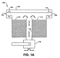
- FIG. 1A is an illustration of one embodiment of tank top corrosion inhibitor dispensing system according to the present invention.
- dispenser 100 comprises a resealable housing 102 formed from base 104 and top 106.
- Resealable housing 102 can be open and closed via fasteners 108 and 110 and can be formed from any suitable material that is both durable and watertight.
- durable it is meant that the material that is used to form housing 102 should remain durable and structurally intact for at least about 6 months.
- watertight it is meant that water vapor should not be able to pass through the material used to form housing 102.
- housing 102 can be formed from any suitable technique including, but not limited to, blow molding, casting, extrusion, etc.
- the polymer materials that are used to form housing 102 can further include a wide variety of polymer modification compounds including, but not limited to, processing aids, UV stabilizers, flame-retardants, anti-mildew compounds, anti-static compounds, anti-bacterial compounds, dyes, colorants, or any combination of two or more thereof.
- housing 102 is not limited to just the fastener embodiment discussed above. Rather, any suitable type of sealing system that permits repeated opening and closing of housing 102 can be used. Suitable sealing systems include, but are not limited to, tape, hinges, screws, bolts, resealable adhesives, or combinations of two or more thereof.
- Device 100 further comprises corrosion inhibitor sections 112 and 114 that are formed from any suitable corrosion inhibiting compound or combination of compounds.
- corrosion inhibiting sections 112 and 114 are formed from one or more volatile, or vapor phase, corrosion inhibiting compounds.
- Such one or more volatile, or vapor phase, corrosion inhibiting compounds can be either liquid or solid compounds that produce a vapor phase corrosion inhibitor that is transmitted down supply tube 116 to valve 118.
- Valve 118 is designed to connect to the top of an aboveground storage tank, or some other enclosure as described above. Valve 118 can either be manually controlled or can be remotely controlled by, for example, a computer. Once valve 118 is opened, then volatile, or vapor phase, corrosion inhibitor is permitted to flow into the empty space at the top of a storage tank (not shown).
- supply tube 116 and valve 118 these portions of device 100 can be manufactured from any of the materials discussed above for housing 102. Additionally, since such devices are known in the art, a detailed discussion of the exact structures of supply tube 116 and valve 118 is omitted herein for the sake of brevity.
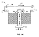
- Figure 1C illustrates a device 300 in accordance with another embodiment of the present invention.
- Device 300 is similar to device 100 except that it does not include valve 118.
- valve 118 is replaced by a coupling 218.
- Coupling 218 can de designed to be attached to a wide range of piping or tank inputs so as to permit delivery of the one or more corrosion inhibitors contained in device 200 to the interior space of, for example, a tank or other enclosure.
- Device 300 can be formed from the same or similar materials that are used to form the other devices of the present invention.
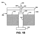
- the devices of the present invention are not limited to just the use of resealable cover structure 220. Rather any type of manual or remotely controlled valve can be used in place of resealable cover structure 220 to permit the selective delivery of the one or more corrosion inhibitors to the interior of an enclosure (e.g ., a aboveground storage tank).
- an enclosure e.g ., a aboveground storage tank
- Figure 2A illustrates a device 400 in accordance with another embodiment of the present invention.
- Device 400 is similar to device 100 except that housing 102 is replaced by a housing 402 that has a sloped cover 406 and a base 404. Additionally, device 400 has a single corrosion inhibitor reservoir 413 that is able to be replenished via the combination of plug 420 and fill-hole 422. When plug 420 is removed, additional corrosion inhibitor can be added to reservoir 413 via fill-hole 422. This permits device 400 to remain in service longer without having to remove device 400 from the top of an enclosure (e.g ., an aboveground storage tank) and service the device offsite.
- Device 400 can be formed from the same or similar materials that are used to form the other devices of the present invention.
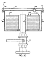
- Figure 2C illustrates a device 600 in accordance with another embodiment of the present invention.
- Device 600 is similar to device 100 and 400 except that device 600 is refillable due to the inclusion of plug 420 and fill-hole 422.
- Device 600 can be formed from the same or similar materials that are used to form the other devices of the present invention.
- Device 700 can be formed from the same or similar materials that are used to form the other devices of the present invention.
- Device 800 can be formed from the same or similar materials that are used to form the other devices of the present invention.
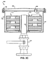
- Figure 3C illustrates a device 900 in accordance with another embodiment of the present invention.
- Device 900 is similar to devices 100 and 400 except that reservoir 413 has been replaced with a multi-level reservoir 713.
- reservoir 713 due to the multi-level nature of reservoir 713, it is formed from some type of degradable material (e.g ., a polymer material).
- the degradable material of reservoir 713 is designed to degrade in the presence of one or more environmental factors such as water vapor, chlorine, heat, sunlight, UV rays, etc.
- Device 900 can be formed from the same or similar materials that are used to form the other devices of the present invention.
- the dispensers disclosed therein are designed to be connected, interconnected, or attached to a suitable delivery system, such as the ones shown in Figures 4 , 5 and 9 , for delivering at least one corrosion inhibitor to at least one enclosure (e.g ., a storage tank).
- a suitable delivery system such as the ones shown in Figures 4 , 5 and 9
- at least one enclosure e.g ., a storage tank.
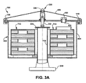
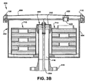
- valve-type or pipe-type connections are shown in relation to the embodiments of Figures 1A through 3C , the present invention is not limited thereto. Instead, any suitable type of connection can be used in the systems of the present invention.
- the dispensers of the present invention can be one time use items or can be designed to be replenished.
- the dispensers of the present invention are designed from any suitable material. Such materials include, but are not limited to, metal, ceramics, plastics, or a combination of one or more of these types of materials. In one embodiment, the material used to form the one or more dispensers of the present invention are selected for their resistance to corrosion, or corrosive elements (e.g ., SO x , NO x , chlorides, oxygen, CO 2 , HCl, water, water vapor, etc.).
- the dispensers of the present invention permit the use of either high or low vapor pressure inhibitors at the same time. In another embodiment, the dispensers of the present invention permit the use of less or non-hazardous low vapor pressure inhibitors and can achieve high speed delivery of such inhibitors into an enclosure. In still another embodiment, the dispensers of the present invention prevent waste of one or more corrosion inhibiting compounds by selectively delivering such compounds only when need ( e.g ., as determined by a set program, as determined in response to a sensor, etc.).
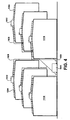
- Figure 4 illustrates the application of various embodiments of the devices of the present invention to a field of aboveground storage tanks. It should be noted that the present invention is not limited to just the application shown in Figure 4 . Rather, the applications for the devices of the present invention are to be broadly construed in accordance with the discussion above.
- Figure 5 is similar In nature to Figure 4 , except that it illustrates a one tank system rather than a multi-tank system. It should be noted that the number of tanks to which the systems of the present invention are applied is not critical. As such, any number of tanks can be protected by just increasing the number of reservoirs and amount of piping utilized.
- corrosion inhibitor dispensers in accordance with devices 100, 200, 300, 400, 500, 600, 700, 800, 900, 1200, 1300, and/or 1400 can be used as corrosion protection device 1002.
- any variety of devices can be used.
- the present invention is not limited to the instance where all of corrosion protection devices 1002 are identical in nature.
- devices 100, 200, 300, 400, 500, 600, 700, 800 and 900 can have multiple supply points rather than just the single supply point shown in Figures 1A through 3C .
- housing 1202 is not limited to just the fastener embodiment discussed above. Rather, any suitable type of sealing system that permits repeated opening and closing of housing 1202 can be used. Suitable sealing systems include, but are not limited to, tape, hinges, screws, bolts, resealable adhesives, or combinations of two or more thereof.
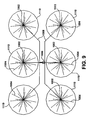
- Figure 9 is a top down view of the system of Figure 4 where like reference numerals represent like parts. Given this, a further explanation of Figure 9 is omitted for the sake of brevity.
Landscapes
- Chemical & Material Sciences (AREA)
- Engineering & Computer Science (AREA)
- Mechanical Engineering (AREA)
- Materials Engineering (AREA)
- Metallurgy (AREA)
- Organic Chemistry (AREA)
- Preventing Corrosion Or Incrustation Of Metals (AREA)
- Filling Or Discharging Of Gas Storage Vessels (AREA)
Claims (10)
- Korrosionsmanagementsystem zur Bereitstellung von Korrosionsschutz für einen Behälter, umfassend:einen Spender, umfassend ein verschließbares Gehäuse, wobei das verschließbare Gehäuse mindestens einen darin enthaltenen korrosionsinhibierenden Teil umfasst, wobei der korrosionsinhibierende Teil mindestens einen Dampfphasenkorrosionsinhibitor umfasst; wobei der Spender zur Bereitstellung des Korrosionsinhibitors an einem oberen Teil des Behälters gestaltet ist;mindestens ein Bereitstellungssystem, das in Kommunikation mit dem verschließbaren Gehäuse steht, wobei das Bereitstellungssystem zum Ermöglichen von selektiver Bereitstellung des mindestens einen Dampfphasenkorrosionsinhibitors an dem Behälter außerhalb des verschließbaren Gehäuses gestaltet ist; undein Schwimmersystem, umfassend ein verschließendes Ventil und ein Stellglied, an dessen unterem Ende der Schwimmer befestigt ist, wobei der Schwimmer das verschließende Ventil basierend auf dem Level einer Flüssigkeit in dem Behälter betätigt, wodurch die Freisetzung von einem oder mehreren Korrosionsinhibitoren in den leeren Teil des Behälters ermöglicht wird.
- Korrosionsmanagementsystem nach Anspruch 1, wobei der Spender mindestens zwei unterschiedliche Dampfphasenkorrosionsinhibitor-Verbindungen enthält.
- Korrosionsmanagementsystem nach den Ansprüchen 1 oder 2, wobei der Spender ferner einen Sensor zum Feststellen der Konzentration von einer oder mehreren korrosiven Verbindungen in dem Behälter umfasst.
- Korrosionsmanagementsystem nach einem der Ansprüche 1 bis 3, wobei die Vorrichtung ferner ein Statusüberwachungssystem umfasst.
- Korrosionsmanagementsystem nach einem der Ansprüche 1 bis 4, wobei das Statusüberwachungssystem das Überwachen der Menge an Korrosionsinhibitor, welche in dem Spender verbleibt, ermöglicht.
- Korrosionsmanagementsystem nach einem der Ansprüche 1 bis 5, wobei der Spender wiederverschließbar ist.
- Korrosionsmanagementsystem nach einem der Ansprüche 1 bis 6, wobei der Spender aus einem Polymermaterial, Stahl oder anderem Metall gebildet ist.
- Korrosionsmanagementsystem nach einem der Ansprüche 1 bis 7, wobei der Spender schwer entflammbar ist.
- Korrosionsmanagementsystem nach einem der Ansprüche 1 bis 8, wobei der Behälter, der geschützt wird, ein Lagertank, ein Speicherreservoir, ein Transportbehälter oder ein Metallgehäuse ist.
- Korrosionsmanagementsystem nach einem der Ansprüche 1 bis 9, wobei der Behälter, der geschützt wird, ein oberirdischer Lagertank ist.
Applications Claiming Priority (2)
| Application Number | Priority Date | Filing Date | Title |
|---|---|---|---|
| US92631407P | 2007-04-26 | 2007-04-26 | |
| PCT/US2008/005392 WO2008134016A1 (en) | 2007-04-26 | 2008-04-25 | Corrosion management systems for controlling, eliminating and/or managing corrosion |
Publications (3)
| Publication Number | Publication Date |
|---|---|
| EP2152938A1 EP2152938A1 (de) | 2010-02-17 |
| EP2152938A4 EP2152938A4 (de) | 2011-08-03 |
| EP2152938B1 true EP2152938B1 (de) | 2013-12-18 |
Family
ID=39925996
Family Applications (1)
| Application Number | Title | Priority Date | Filing Date |
|---|---|---|---|
| EP20080743322 Not-in-force EP2152938B1 (de) | 2007-04-26 | 2008-04-25 | Korrosionsmanagementsysteme zur einschränkung, zur eliminierung und/oder zum management von korrosion |
Country Status (10)
| Country | Link |
|---|---|
| US (2) | US8309021B2 (de) |
| EP (1) | EP2152938B1 (de) |
| AR (1) | AR066322A1 (de) |
| BR (1) | BRPI0810614A2 (de) |
| CA (1) | CA2685288A1 (de) |
| EA (1) | EA019355B1 (de) |
| MX (1) | MX2009011547A (de) |
| MY (1) | MY149958A (de) |
| TW (1) | TW200916604A (de) |
| WO (1) | WO2008134016A1 (de) |
Families Citing this family (4)
| Publication number | Priority date | Publication date | Assignee | Title |
|---|---|---|---|---|
| US8418757B2 (en) | 2010-05-06 | 2013-04-16 | Northern Technologies International Corporation | Corrosion management systems for vertically oriented structures |
| DE102013222845A1 (de) | 2013-11-11 | 2015-05-13 | Zf Friedrichshafen Ag | Korrosionsschutzmittelbehälter |
| US9656201B2 (en) | 2014-12-24 | 2017-05-23 | Northern Technologies International Corporation | Smart, on-demand controlled release corrosion protection and/or prevention of metals in an enclosure |
| US12398472B2 (en) | 2021-12-16 | 2025-08-26 | Saudi Arabian Oil Company | Intelligent system using an IoT architectural framework to control deployment of volatile corrosion inhibitors (VCIs) for soil-side corrosion mitigation of aboveground storage tanks |
Family Cites Families (11)
| Publication number | Priority date | Publication date | Assignee | Title |
|---|---|---|---|---|
| US2634223A (en) * | 1949-07-01 | 1953-04-07 | Standard Oil Dev Co | Method for inhibiting corrosion in storage vessels |
| US3595438A (en) * | 1969-01-06 | 1971-07-27 | Economics Lab | Automatic detergent dispenser system |
| US4290912A (en) | 1980-02-21 | 1981-09-22 | Northern Instruments Corporation | Volatile corrosion inhibiting article |
| US5137694A (en) * | 1985-05-08 | 1992-08-11 | Ecolab Inc. | Industrial solid detergent dispenser and cleaning system |
| US5184939A (en) * | 1988-08-17 | 1993-02-09 | Solomon Stuart G | Above-ground storage system |
| US5320778A (en) | 1988-08-23 | 1994-06-14 | Cortec Corporation | Vapor phase corrosion inhibitor-desiccant material |
| EP0653454B1 (de) | 1993-11-09 | 2000-01-12 | Cortec Corporation | Antikorrosionsfilm mit aufgearbeitetem Harz |
| JP2002257302A (ja) * | 2001-02-27 | 2002-09-11 | Miura Co Ltd | 腐食抑制剤の薬注方法 |
| US20030019872A1 (en) | 2001-07-30 | 2003-01-30 | Lyublinski Efim Ya | Systems and methods for preventing and/or reducing corrosion in various types of tanks, containers and closed systems |
| WO2003062346A1 (en) * | 2002-01-22 | 2003-07-31 | Northern Technologies International Corporation | Corrosion inhibiting formula and corrosion inhibiting articles using same |
| US7794583B2 (en) | 2007-04-05 | 2010-09-14 | Northern Technologies International Corp. | Synergistic corrosion management systems for controlling, eliminating and/or managing corrosion |
-
2008
- 2008-04-25 EP EP20080743322 patent/EP2152938B1/de not_active Not-in-force
- 2008-04-25 WO PCT/US2008/005392 patent/WO2008134016A1/en not_active Ceased
- 2008-04-25 MX MX2009011547A patent/MX2009011547A/es active IP Right Grant
- 2008-04-25 US US12/597,430 patent/US8309021B2/en not_active Expired - Fee Related
- 2008-04-25 EA EA200901455A patent/EA019355B1/ru not_active IP Right Cessation
- 2008-04-25 TW TW97115282A patent/TW200916604A/zh unknown
- 2008-04-25 MY MYPI20094500A patent/MY149958A/en unknown
- 2008-04-25 BR BRPI0810614 patent/BRPI0810614A2/pt not_active Application Discontinuation
- 2008-04-25 CA CA 2685288 patent/CA2685288A1/en active Pending
- 2008-04-28 AR ARP080101784 patent/AR066322A1/es unknown
-
2012
- 2012-07-30 US US13/561,604 patent/US8354072B2/en not_active Expired - Fee Related
Also Published As
| Publication number | Publication date |
|---|---|
| US20120294768A1 (en) | 2012-11-22 |
| CA2685288A1 (en) | 2008-11-06 |
| MX2009011547A (es) | 2010-04-01 |
| US20100209289A1 (en) | 2010-08-19 |
| MY149958A (en) | 2013-11-15 |
| EP2152938A1 (de) | 2010-02-17 |
| WO2008134016A1 (en) | 2008-11-06 |
| TW200916604A (en) | 2009-04-16 |
| US8309021B2 (en) | 2012-11-13 |
| EA019355B1 (ru) | 2014-03-31 |
| US8354072B2 (en) | 2013-01-15 |
| AR066322A1 (es) | 2009-08-12 |
| EP2152938A4 (de) | 2011-08-03 |
| EA200901455A1 (ru) | 2010-04-30 |
| BRPI0810614A2 (pt) | 2014-10-21 |
Similar Documents
| Publication | Publication Date | Title |
|---|---|---|
| US8377531B2 (en) | Systems and methods for preventing and/or reducing corrosion in various types of tanks containers and closed systems | |
| CA2682853C (en) | Synergistic corrosion management systems for controlling, eliminating and/or managing corrosion | |
| US11840399B2 (en) | Gas blanketing management of low-pressure hydrocarbon tanks | |
| US8354072B2 (en) | Corrosion management systems for controlling, eliminating and/or managing corrosion | |
| US8720481B2 (en) | Fluid leak detection and shutdown apparatus | |
| World Health Organization | Water safety in distribution systems | |
| CN1493803A (zh) | 用于压力容器的失效保护排气阀 | |
| US20170350230A1 (en) | Apparatus and Method for Detection of Corrosion | |
| US9169720B2 (en) | Corrosion management systems for vertically oriented structures | |
| US20190330939A1 (en) | Method and apparatus for autonomous injectable liquid dispensing | |
| US5096006A (en) | Apparatus for storing chlorine gas | |
| US7336190B2 (en) | Early detection and advanced warning “waste is backing up” apparatus and method | |
| Williams et al. | Design and testing of USEPA'S flint pipe rig for corrosion control evaluation | |
| JP2012172348A (ja) | 直結型非常時用飲料水タンク装置 | |
| CN214650658U (zh) | 一种氯化石蜡生产中盐酸中间储罐 | |
| US8910504B2 (en) | Device for compensating a filling level | |
| US20170130075A1 (en) | Articles comprising a surface spreading agent, oilfield water storage systems employing the same, and methods of managing the oilfield water storage systems | |
| KR102018428B1 (ko) | 누설 감지 기능을 구비하는 내용물 저장 탱크 | |
| Morris et al. | Solar Cal Poly Water Systems | |
| Geyer | Bringing storage tanks to the surface | |
| Inspectorate | Design Guidelines for the Construction of Fixed Bulk Distillate Installation Underground in Coal Mines MDG No 7 March 1995 |
Legal Events
| Date | Code | Title | Description |
|---|---|---|---|
| PUAI | Public reference made under article 153(3) epc to a published international application that has entered the european phase |
Free format text: ORIGINAL CODE: 0009012 |
|
| 17P | Request for examination filed |
Effective date: 20091124 |
|
| AK | Designated contracting states |
Kind code of ref document: A1 Designated state(s): AT BE BG CH CY CZ DE DK EE ES FI FR GB GR HR HU IE IS IT LI LT LU LV MC MT NL NO PL PT RO SE SI SK TR |
|
| AX | Request for extension of the european patent |
Extension state: AL BA MK RS |
|
| DAX | Request for extension of the european patent (deleted) | ||
| A4 | Supplementary search report drawn up and despatched |
Effective date: 20110705 |
|
| RIC1 | Information provided on ipc code assigned before grant |
Ipc: B65D 81/26 20060101ALI20110629BHEP Ipc: C23F 11/00 20060101AFI20110629BHEP |
|
| 17Q | First examination report despatched |
Effective date: 20121024 |
|
| GRAP | Despatch of communication of intention to grant a patent |
Free format text: ORIGINAL CODE: EPIDOSNIGR1 |
|
| INTG | Intention to grant announced |
Effective date: 20130719 |
|
| GRAS | Grant fee paid |
Free format text: ORIGINAL CODE: EPIDOSNIGR3 |
|
| GRAA | (expected) grant |
Free format text: ORIGINAL CODE: 0009210 |
|
| AK | Designated contracting states |
Kind code of ref document: B1 Designated state(s): AT BE BG CH CY CZ DE DK EE ES FI FR GB GR HR HU IE IS IT LI LT LU LV MC MT NL NO PL PT RO SE SI SK TR |
|
| REG | Reference to a national code |
Ref country code: GB Ref legal event code: FG4D |
|
| REG | Reference to a national code |
Ref country code: CH Ref legal event code: EP |
|
| REG | Reference to a national code |
Ref country code: AT Ref legal event code: REF Ref document number: 645688 Country of ref document: AT Kind code of ref document: T Effective date: 20140115 |
|
| REG | Reference to a national code |
Ref country code: IE Ref legal event code: FG4D |
|
| REG | Reference to a national code |
Ref country code: DE Ref legal event code: R096 Ref document number: 602008029400 Country of ref document: DE Effective date: 20140213 |
|
| REG | Reference to a national code |
Ref country code: NL Ref legal event code: VDEP Effective date: 20131218 |
|
| PG25 | Lapsed in a contracting state [announced via postgrant information from national office to epo] |
Ref country code: HR Free format text: LAPSE BECAUSE OF FAILURE TO SUBMIT A TRANSLATION OF THE DESCRIPTION OR TO PAY THE FEE WITHIN THE PRESCRIBED TIME-LIMIT Effective date: 20131218 Ref country code: NO Free format text: LAPSE BECAUSE OF FAILURE TO SUBMIT A TRANSLATION OF THE DESCRIPTION OR TO PAY THE FEE WITHIN THE PRESCRIBED TIME-LIMIT Effective date: 20140318 Ref country code: LT Free format text: LAPSE BECAUSE OF FAILURE TO SUBMIT A TRANSLATION OF THE DESCRIPTION OR TO PAY THE FEE WITHIN THE PRESCRIBED TIME-LIMIT Effective date: 20131218 Ref country code: SE Free format text: LAPSE BECAUSE OF FAILURE TO SUBMIT A TRANSLATION OF THE DESCRIPTION OR TO PAY THE FEE WITHIN THE PRESCRIBED TIME-LIMIT Effective date: 20131218 Ref country code: FI Free format text: LAPSE BECAUSE OF FAILURE TO SUBMIT A TRANSLATION OF THE DESCRIPTION OR TO PAY THE FEE WITHIN THE PRESCRIBED TIME-LIMIT Effective date: 20131218 |
|
| REG | Reference to a national code |
Ref country code: AT Ref legal event code: MK05 Ref document number: 645688 Country of ref document: AT Kind code of ref document: T Effective date: 20131218 |
|
| REG | Reference to a national code |
Ref country code: LT Ref legal event code: MG4D |
|
| PG25 | Lapsed in a contracting state [announced via postgrant information from national office to epo] |
Ref country code: LV Free format text: LAPSE BECAUSE OF FAILURE TO SUBMIT A TRANSLATION OF THE DESCRIPTION OR TO PAY THE FEE WITHIN THE PRESCRIBED TIME-LIMIT Effective date: 20131218 |
|
| PG25 | Lapsed in a contracting state [announced via postgrant information from national office to epo] |
Ref country code: BE Free format text: LAPSE BECAUSE OF FAILURE TO SUBMIT A TRANSLATION OF THE DESCRIPTION OR TO PAY THE FEE WITHIN THE PRESCRIBED TIME-LIMIT Effective date: 20131218 Ref country code: IS Free format text: LAPSE BECAUSE OF FAILURE TO SUBMIT A TRANSLATION OF THE DESCRIPTION OR TO PAY THE FEE WITHIN THE PRESCRIBED TIME-LIMIT Effective date: 20140418 Ref country code: EE Free format text: LAPSE BECAUSE OF FAILURE TO SUBMIT A TRANSLATION OF THE DESCRIPTION OR TO PAY THE FEE WITHIN THE PRESCRIBED TIME-LIMIT Effective date: 20131218 |
|
| PG25 | Lapsed in a contracting state [announced via postgrant information from national office to epo] |
Ref country code: NL Free format text: LAPSE BECAUSE OF FAILURE TO SUBMIT A TRANSLATION OF THE DESCRIPTION OR TO PAY THE FEE WITHIN THE PRESCRIBED TIME-LIMIT Effective date: 20131218 Ref country code: RO Free format text: LAPSE BECAUSE OF FAILURE TO SUBMIT A TRANSLATION OF THE DESCRIPTION OR TO PAY THE FEE WITHIN THE PRESCRIBED TIME-LIMIT Effective date: 20131218 Ref country code: PT Free format text: LAPSE BECAUSE OF FAILURE TO SUBMIT A TRANSLATION OF THE DESCRIPTION OR TO PAY THE FEE WITHIN THE PRESCRIBED TIME-LIMIT Effective date: 20140418 Ref country code: ES Free format text: LAPSE BECAUSE OF FAILURE TO SUBMIT A TRANSLATION OF THE DESCRIPTION OR TO PAY THE FEE WITHIN THE PRESCRIBED TIME-LIMIT Effective date: 20131218 Ref country code: PL Free format text: LAPSE BECAUSE OF FAILURE TO SUBMIT A TRANSLATION OF THE DESCRIPTION OR TO PAY THE FEE WITHIN THE PRESCRIBED TIME-LIMIT Effective date: 20131218 Ref country code: SK Free format text: LAPSE BECAUSE OF FAILURE TO SUBMIT A TRANSLATION OF THE DESCRIPTION OR TO PAY THE FEE WITHIN THE PRESCRIBED TIME-LIMIT Effective date: 20131218 Ref country code: CY Free format text: LAPSE BECAUSE OF FAILURE TO SUBMIT A TRANSLATION OF THE DESCRIPTION OR TO PAY THE FEE WITHIN THE PRESCRIBED TIME-LIMIT Effective date: 20131218 Ref country code: AT Free format text: LAPSE BECAUSE OF FAILURE TO SUBMIT A TRANSLATION OF THE DESCRIPTION OR TO PAY THE FEE WITHIN THE PRESCRIBED TIME-LIMIT Effective date: 20131218 |
|
| PGFP | Annual fee paid to national office [announced via postgrant information from national office to epo] |
Ref country code: CZ Payment date: 20140416 Year of fee payment: 7 |
|
| REG | Reference to a national code |
Ref country code: DE Ref legal event code: R097 Ref document number: 602008029400 Country of ref document: DE |
|
| PLBE | No opposition filed within time limit |
Free format text: ORIGINAL CODE: 0009261 |
|
| STAA | Information on the status of an ep patent application or granted ep patent |
Free format text: STATUS: NO OPPOSITION FILED WITHIN TIME LIMIT |
|
| PG25 | Lapsed in a contracting state [announced via postgrant information from national office to epo] |
Ref country code: DK Free format text: LAPSE BECAUSE OF FAILURE TO SUBMIT A TRANSLATION OF THE DESCRIPTION OR TO PAY THE FEE WITHIN THE PRESCRIBED TIME-LIMIT Effective date: 20131218 |
|
| REG | Reference to a national code |
Ref country code: DE Ref legal event code: R119 Ref document number: 602008029400 Country of ref document: DE |
|
| 26N | No opposition filed |
Effective date: 20140919 |
|
| PG25 | Lapsed in a contracting state [announced via postgrant information from national office to epo] |
Ref country code: LU Free format text: LAPSE BECAUSE OF FAILURE TO SUBMIT A TRANSLATION OF THE DESCRIPTION OR TO PAY THE FEE WITHIN THE PRESCRIBED TIME-LIMIT Effective date: 20140425 Ref country code: MC Free format text: LAPSE BECAUSE OF FAILURE TO SUBMIT A TRANSLATION OF THE DESCRIPTION OR TO PAY THE FEE WITHIN THE PRESCRIBED TIME-LIMIT Effective date: 20131218 |
|
| REG | Reference to a national code |
Ref country code: CH Ref legal event code: PL |
|
| REG | Reference to a national code |
Ref country code: DE Ref legal event code: R097 Ref document number: 602008029400 Country of ref document: DE Effective date: 20140919 |
|
| REG | Reference to a national code |
Ref country code: IE Ref legal event code: MM4A |
|
| REG | Reference to a national code |
Ref country code: DE Ref legal event code: R119 Ref document number: 602008029400 Country of ref document: DE Effective date: 20141101 |
|
| PG25 | Lapsed in a contracting state [announced via postgrant information from national office to epo] |
Ref country code: CH Free format text: LAPSE BECAUSE OF NON-PAYMENT OF DUE FEES Effective date: 20140430 Ref country code: LI Free format text: LAPSE BECAUSE OF NON-PAYMENT OF DUE FEES Effective date: 20140430 Ref country code: DE Free format text: LAPSE BECAUSE OF NON-PAYMENT OF DUE FEES Effective date: 20141101 |
|
| REG | Reference to a national code |
Ref country code: FR Ref legal event code: PLFP Year of fee payment: 8 |
|
| PG25 | Lapsed in a contracting state [announced via postgrant information from national office to epo] |
Ref country code: IE Free format text: LAPSE BECAUSE OF NON-PAYMENT OF DUE FEES Effective date: 20140425 |
|
| PG25 | Lapsed in a contracting state [announced via postgrant information from national office to epo] |
Ref country code: SI Free format text: LAPSE BECAUSE OF FAILURE TO SUBMIT A TRANSLATION OF THE DESCRIPTION OR TO PAY THE FEE WITHIN THE PRESCRIBED TIME-LIMIT Effective date: 20131218 |
|
| PGFP | Annual fee paid to national office [announced via postgrant information from national office to epo] |
Ref country code: GB Payment date: 20150423 Year of fee payment: 8 |
|
| PGFP | Annual fee paid to national office [announced via postgrant information from national office to epo] |
Ref country code: FR Payment date: 20150422 Year of fee payment: 8 |
|
| PG25 | Lapsed in a contracting state [announced via postgrant information from national office to epo] |
Ref country code: CZ Free format text: LAPSE BECAUSE OF NON-PAYMENT OF DUE FEES Effective date: 20150425 |
|
| PG25 | Lapsed in a contracting state [announced via postgrant information from national office to epo] |
Ref country code: MT Free format text: LAPSE BECAUSE OF FAILURE TO SUBMIT A TRANSLATION OF THE DESCRIPTION OR TO PAY THE FEE WITHIN THE PRESCRIBED TIME-LIMIT Effective date: 20131218 |
|
| PG25 | Lapsed in a contracting state [announced via postgrant information from national office to epo] |
Ref country code: BG Free format text: LAPSE BECAUSE OF FAILURE TO SUBMIT A TRANSLATION OF THE DESCRIPTION OR TO PAY THE FEE WITHIN THE PRESCRIBED TIME-LIMIT Effective date: 20131218 |
|
| PG25 | Lapsed in a contracting state [announced via postgrant information from national office to epo] |
Ref country code: IT Free format text: LAPSE BECAUSE OF FAILURE TO SUBMIT A TRANSLATION OF THE DESCRIPTION OR TO PAY THE FEE WITHIN THE PRESCRIBED TIME-LIMIT Effective date: 20131218 Ref country code: GR Free format text: LAPSE BECAUSE OF FAILURE TO SUBMIT A TRANSLATION OF THE DESCRIPTION OR TO PAY THE FEE WITHIN THE PRESCRIBED TIME-LIMIT Effective date: 20140319 |
|
| PG25 | Lapsed in a contracting state [announced via postgrant information from national office to epo] |
Ref country code: HU Free format text: LAPSE BECAUSE OF FAILURE TO SUBMIT A TRANSLATION OF THE DESCRIPTION OR TO PAY THE FEE WITHIN THE PRESCRIBED TIME-LIMIT; INVALID AB INITIO Effective date: 20080425 Ref country code: TR Free format text: LAPSE BECAUSE OF FAILURE TO SUBMIT A TRANSLATION OF THE DESCRIPTION OR TO PAY THE FEE WITHIN THE PRESCRIBED TIME-LIMIT Effective date: 20131218 |
|
| GBPC | Gb: european patent ceased through non-payment of renewal fee |
Effective date: 20160425 |
|
| REG | Reference to a national code |
Ref country code: FR Ref legal event code: ST Effective date: 20161230 |
|
| PG25 | Lapsed in a contracting state [announced via postgrant information from national office to epo] |
Ref country code: FR Free format text: LAPSE BECAUSE OF NON-PAYMENT OF DUE FEES Effective date: 20160502 Ref country code: GB Free format text: LAPSE BECAUSE OF NON-PAYMENT OF DUE FEES Effective date: 20160425 |