EP2153385B1 - Überwachungsvorrichtung und system - Google Patents
Überwachungsvorrichtung und system Download PDFInfo
- Publication number
- EP2153385B1 EP2153385B1 EP08747917.6A EP08747917A EP2153385B1 EP 2153385 B1 EP2153385 B1 EP 2153385B1 EP 08747917 A EP08747917 A EP 08747917A EP 2153385 B1 EP2153385 B1 EP 2153385B1
- Authority
- EP
- European Patent Office
- Prior art keywords
- individual signal
- signal unit
- central control
- control facility
- steps
- Prior art date
- Legal status (The legal status is an assumption and is not a legal conclusion. Google has not performed a legal analysis and makes no representation as to the accuracy of the status listed.)
- Active
Links
Images





















Classifications
-
- H—ELECTRICITY
- H04—ELECTRIC COMMUNICATION TECHNIQUE
- H04L—TRANSMISSION OF DIGITAL INFORMATION, e.g. TELEGRAPHIC COMMUNICATION
- H04L12/00—Data switching networks
- H04L12/28—Data switching networks characterised by path configuration, e.g. LAN [Local Area Networks] or WAN [Wide Area Networks]
- H04L12/2803—Home automation networks
- H04L12/2823—Reporting information sensed by appliance or service execution status of appliance services in a home automation network
- H04L12/2825—Reporting to a device located outside the home and the home network
-
- H—ELECTRICITY
- H04—ELECTRIC COMMUNICATION TECHNIQUE
- H04L—TRANSMISSION OF DIGITAL INFORMATION, e.g. TELEGRAPHIC COMMUNICATION
- H04L67/00—Network arrangements or protocols for supporting network services or applications
- H04L67/01—Protocols
- H04L67/02—Protocols based on web technology, e.g. hypertext transfer protocol [HTTP]
- H04L67/025—Protocols based on web technology, e.g. hypertext transfer protocol [HTTP] for remote control or remote monitoring of applications
-
- G—PHYSICS
- G05—CONTROLLING; REGULATING
- G05B—CONTROL OR REGULATING SYSTEMS IN GENERAL; FUNCTIONAL ELEMENTS OF SUCH SYSTEMS; MONITORING OR TESTING ARRANGEMENTS FOR SUCH SYSTEMS OR ELEMENTS
- G05B11/00—Automatic controllers
- G05B11/01—Automatic controllers electric
- G05B11/012—Automatic controllers electric details of the transmission means
-
- G—PHYSICS
- G05—CONTROLLING; REGULATING
- G05B—CONTROL OR REGULATING SYSTEMS IN GENERAL; FUNCTIONAL ELEMENTS OF SUCH SYSTEMS; MONITORING OR TESTING ARRANGEMENTS FOR SUCH SYSTEMS OR ELEMENTS
- G05B15/00—Systems controlled by a computer
- G05B15/02—Systems controlled by a computer electric
-
- H—ELECTRICITY
- H04—ELECTRIC COMMUNICATION TECHNIQUE
- H04B—TRANSMISSION
- H04B7/00—Radio transmission systems, i.e. using radiation field
- H04B7/14—Relay systems
- H04B7/15—Active relay systems
- H04B7/185—Space-based or airborne stations; Stations for satellite systems
- H04B7/1851—Systems using a satellite or space-based relay
-
- H—ELECTRICITY
- H04—ELECTRIC COMMUNICATION TECHNIQUE
- H04L—TRANSMISSION OF DIGITAL INFORMATION, e.g. TELEGRAPHIC COMMUNICATION
- H04L67/00—Network arrangements or protocols for supporting network services or applications
- H04L67/01—Protocols
- H04L67/12—Protocols specially adapted for proprietary or special-purpose networking environments, e.g. medical networks, sensor networks, networks in vehicles or remote metering networks
-
- H—ELECTRICITY
- H04—ELECTRIC COMMUNICATION TECHNIQUE
- H04W—WIRELESS COMMUNICATION NETWORKS
- H04W4/00—Services specially adapted for wireless communication networks; Facilities therefor
- H04W4/70—Services for machine-to-machine communication [M2M] or machine type communication [MTC]
-
- H—ELECTRICITY
- H04—ELECTRIC COMMUNICATION TECHNIQUE
- H04L—TRANSMISSION OF DIGITAL INFORMATION, e.g. TELEGRAPHIC COMMUNICATION
- H04L12/00—Data switching networks
- H04L12/28—Data switching networks characterised by path configuration, e.g. LAN [Local Area Networks] or WAN [Wide Area Networks]
- H04L12/2803—Home automation networks
- H04L12/2816—Controlling appliance services of a home automation network by calling their functionalities
- H04L12/2818—Controlling appliance services of a home automation network by calling their functionalities from a device located outside both the home and the home network
Definitions
- the present invention relates to error and incident reporting apparatus and systems and, more particularly, to a system adapted to monitoring and acting upon status signals emanating from widely diverse and geographically separated installations.
- US5933080 discloses a "Mayday" alert system which reports a traffic accident to a Mayday centre for reporting the accident to a number of predetermined addressees. Again there is no provision for communication between a person involved in an accident with a monitoring authority except in the trivial case of transmitting a reset call.
- US2005/0198121 discloses a method for integrating applications from different enterprises into a single interface to be presented to the user.
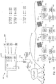
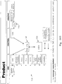
- FIG. 1A there is shown a reconfigurable, collaboratively expandable monitoring system 200 in accordance with a first preferred embodiment of the present invention.
- the system comprises components as described with reference to Figure 1B (see below).
- third party providers 201 in this instance, labelled P 1 , P 2 , P 3 ......P N
- tools are available for the user/owner/nominated recipient 30
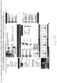
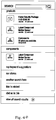
- the tools 202 are made available to a user 30 preferably via a web interface screen 203 which will include a tool assembly pane 204 where an individual user 30 can assemble a schedule of predefined steps 205 (step 1, 2, 3 administratN) to in response to events 206 (event 1, 2, 3 «N).
- a user 30 of one or more of the individual signal units 22 can program responses to events detected by the individual signal units 22 using tools 202 selected from an ever-increasing number of tools based on tools supplied by third party providers 201.
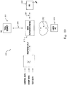
- FIG 1 is a diagrammatic representation of the apparatus and connections included in a monitoring system 10 according to a preferred embodiment of the invention.
- a central control facility 12 includes a data processing server 14 and data storage 16, linked to a transceiver 18.
- Central control facility 12 is in radio communication with a communication network such as a mobile phone network, or for example as shown in Figure 1 , with at least one communication satellite 20, by means of transceiver 18.
- GSM Global System for Mobile Communications
- GPRS General Packet Radio Service
- Individual signal units 22 belong to registered users of the system and may be located anywhere within the signal footprint of a communication satellite (or satellites) 20, or of some other communication network.
- Individual signal units 22 each are assigned a unique identifying code, and may take a number of physical configurations depending on the environment in which they are to be located.
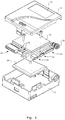
- Figure 3 shows one preferred form of an individual signal unit, comprising enclosure 50 with various input and output devices. In some preferred forms at least, they will comprise a rugged, moisture and tamper-proof outer casing with internal power supply and a selection of bracketry and other attachment means for affixing the devices to a variety of structures and surfaces. In other preferred forms the device may be incorporated in an item of equipment at manufacture, for example in the lantern structure of street lights.
- the apparatus of a monitoring system may include a number of standard sensor devices available for purchase along with, or in addition to the individual signal unit 22.
- Each sensor device is adapted to respond to a predefined stimulus, and may include sensors for power status, smoke detection, motion detection, door or window opening, button press, fluid level, tampering, location via the GPS system and video camera, for example.
- These standard sensor devices are provided as a simple plug-in to the individual signal unit 22, via one of the input connection 64 or USB port shown in Figure 4 , or other standard interface ports provided on the device.
- An individual signal unit 22 may further be provided with internal error monitoring facilities, such as a power supply failure.
- individual signal units 22 are equipped with interference sensors to alert the central control facility 12 of tampering by unauthorised persons, or disturbance by animals for example.
- Individual signal units 22 in at least one preferred embodiment are provided with output relays to activate one or more external devices according to pre-programmed responses to sensor monitored events. Examples may include the activation of audio and/or visual alarms, the switching on of security lighting, closure of fire doors and so forth.
- the power supply and control module 42 is adapted to maintain individual signal unit 22 in a passive, standby state until receiving a signal from an external event sensor. Such a signal initiates a powering up of the device, enabling it to transmit its unique encrypted identifying code to the central control facility. After transmission of this signal the individual signal unit powers down and returns to its passive standby state.
- An individual signal unit 20 may also be brought into a powered up state on command from the central control facility 12. This powering up may be for the purpose of reprogramming the individual signal unit 22 to install a new response procedure, for example after the installation of a new, or an additional external event sensor, relocation of the unit, or to modify an existing procedure.
- an individual signal unit 22 is provided with data entry and display facilities, such programming or reprogramming of the unit may be performed at the device itself.
- the new or modified data is transmitted to the central control facility to update its responses to any signals received from the individual signal unit as required.
- individual signal unit 22 will transmit a signal via the network 21 and a satellite 20, reporting the event to the central control facility 12.
- an individual signal unit 22 may continue to transmit its signal at intervals for a pre-defined period as an aid in location of the device by service personnel alerted by the central control facility 12 as described below.
- a received signal is acted upon by the central control facility 12, notifying any of a number of nominated recipients 30 according to a pre-established protocol negotiated between the registered user of the individual signal unit 22 and the control facility. Notification of details of a monitored event could be made in the form of an email via the Internet 29 as shown in Figure 1 , by facsimile transmission or over the distributed network 21 to any personal communication device.
- one nominated recipient 30 will be the registered user or owner of the individual signal unit from which the alerting signal was received.
- nominated recipients may also include service providers, who are automatically notified of the occurrence and the nature of the event, the location of the individual signal unit and any other pre-defined details. Service providers may include police, fire and ambulance services, or equipment servicing personnel for example.
- the owner of the unit may elect that third parties be contacted only on receipt by the central control facility of authorisation from the owner.
- the central control facility then issues the unique identification code for the individual signal unit.
- an individual signal unit may be pre-programmed at manufacture with its unique identifying code.
- the applicant user or owner nominates a service provider of the GSM, GPRS or other communication system, for billing purposes, or alternatively, the central control facility makes this arrangement, with billing for such service included in the overall charge for use of the system.
- enclosure 50 comprises a base portion 52 and cover portion 54.
- a communication module 56 for example using the General Packet Radio Service (GPRS) standard for communication with a communication network, and antenna jack 58.
- GPRS General Packet Radio Service
- enclosure 50 also contains within enclosure 50, and various input and output connections, including power input/outputs 62, sensor inputs 64, device relay connections 66 and a universal serial bus (USB port) 68.
- Individual signal unit 22 may also be provided with status indicating light emitting diodes (LEDs) 70.
- Enclosure 50 is provided with a space, for example space 72 on cover 54, for display of a code used in the registration of the unit with the central control facility.
- Each individual signal unit 22 is adapted to monitor the status of some aspect of an item of infrastructure, such as for example illustrated in Figure 1 , a gate 22, irrigation control sluice 24 or tool shed 26.
- the power supply 42 is rechargeable by means of a solar panel 48, but may also comprise batteries rechargeable from a mains power source, or replaceable battery packs. Where an individual signal unit has been incorporated in some item of infrastructure already provided with a power supply, such as in the street light example, power to the unit may be provided from that external supply.
- An individual signal unit 22 may be provided with at least one external event sensor 44 incorporated within the device itself, but individual signal units 22 are more preferably provided with a sensor interface allowing the unit to accept signals from a number of external event sensors connected to the interface.
- an individual signal unit 22 may monitor a number of aspects of a remotely located facility, such as the doors and windows of a building or various items of equipment located on a service vehicle.
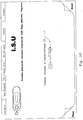
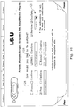
- the ISU may include the following components.
- the application scripts (software) loaded into the GSM engine 74 allow the module to monitor the external sensors and devices connected to the ISU device and generate messages over the GPRS network to the central control facility server whenever there is a change in the status of these external sensors or devices.
- the typical operation will be for the GSM engine to connect to a known IP socket on a server at a known IP address.
- the message passed to the server via this connection will include the identification of the ISU device (typically the 'phone number associated with the SIM card) and the details of the input status change.
- the GSM engine has a push button switch (S1 on the circuit diagram of Figure 5 ) which allows the GSM engine to be turned on and off.
- An LED (light emitting diode) is provided to give an indication of the status of the ISU device.
- the LED When the LED is permanently off, the device is powered down.
- the LED When the LED is blinking quickly (approximately 1 second period), the GSM engine is searching for the GSM network and attempting to register itself with the network.
- the LED When the LED is blinking slowly (approximately 3 second period), the GSM engine has registered itself with the GSM network and is in a state that will allow it to make a connection with a server should one of the inputs change state.
- the LED When the LED is permanently on, there is an active call being made by the device.
- a visible indication of the charge status of the battery is provided using an LED (light emitting diode).
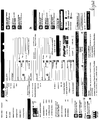
- the ISU device has a USB connection to allow the module to be connected to a Personal Computer. This connection allows the application scripts (software) to be updated in the GSM Engine. Power is also drawn from the Personal Computer to recharge the LiIon battery. The power for the USB interface device (U6 on the circuit diagram) is taken from the USB connector. This minimises the current drawn from the LiIon battery to extend the operational time between charges. Interface components (U4 and U5 on the circuit diagram) isolate the connections between the USB device and the GSM engine when either the USB port is disconnected (USB device powered down) or the GSM engine has been turned off.
- a protection device (U7 on the circuit diagram) has been included on the USB port to protect the USB device from electrostatic discharge onto the pins of the USB connector.
- the prototype ISU device implements 4 external sensor inputs. These connections are available on a dedicated input connector (J2 on the circuit diagram) and on the special attachment connector (J4 on the circuit diagram). These inputs have been configured to allow external sensors to simply connect these input signals to a 0Volt return signal (available on both connectors) using a relay contact closure. This is the typical output from a wide range of sensors.
- An interface component (U3 on the circuit diagram) is provided to isolate the input signals from the GSM engine when the GSM engine has been turned off.
- the prototype ISU device implements 2 controlled outputs. These outputs allow external devices to be switched by the ISU device. These outputs are implemented using transistors Q1 and Q2. The connections to external devices can be made either by the dedicated output connector (J1 on the circuit diagram) or the special attachment connector (J4 on the circuit diagram).
- a special attachment connector has been provided on the ISU device to allow it to be plugged into purpose built sensors. These sensors will be engineered to accommodate the ISU device and all of the required connections between the two devices are made through the single attachment connector.
- This connector supports attachments that are self-powered and are capable of providing current to recharge the battery in the ISU, as well as attachments that do not have their own power supply and require current from the ISU device's battery to operate.
- the apparatus of a monitoring system may include a number of standard sensor devices available for purchase along with, or in addition to the individual signal unit 22.
- Each sensor device is adapted to respond to a predefined stimulus, and may include sensors for power status, smoke detection, motion detection, door or window opening, button press, fluid level, tampering, location via the GPS system and video camera, for example.
- These standard sensor devices are provided as a simple plug-in to the individual signal unit 22, via one of the input connection 64 or USB port shown in Figure 4 , or other standard interface ports provided on the device.
- An individual signal unit 22 may further be provided with internal error monitoring facilities, such as a power supply failure.
- individual signal units 22 are equipped with interference sensors to alert the central control facility 12 of tampering by unauthorised persons, or disturbance by animals for example.
- the power supply and control module 42 is adapted to maintain individual signal unit 22 in a passive, standby state until receiving a signal from an external event sensor. Such a signal initiates a powering up of the device, enabling it to transmit its unique encrypted identifying code to the central control facility. After transmission of this signal the individual signal unit powers down and returns to its passive standby state.
- An individual signal unit 20 may also be brought into a powered up state on command from the central control facility 12. This powering up may be for the purpose of reprogramming the individual signal unit 22 to install a new response procedure, for example after the installation of a new, or an additional external event sensor, relocation of the unit, or to modify an existing procedure.
- an individual signal unit 22 is provided with data entry and display facilities, such programming or reprogramming of the unit may be performed at the device itself.
- the new or modified data is transmitted to the central control facility to update its responses to any signals received from the individual signal unit as required.
- individual signal unit 22 will transmit a signal via the network 21 and a satellite 20, reporting the event to the central control facility 12.
- a signal sent by an individual signal unit 22 consists solely of its unique encrypted identifying code. No data is sent with this code.
- the information as to what a receipt of this code by the central control facility means, is stored in the central processing computers of the facility. This information, which is supplied by and under the control of the registered owner of the individual signal unit, may include instructions as to what actions are to be taken in response to the signal.
- the individual signal unit 22 is only enabled to transmit a single encrypted identifying code, it may do so in various ways to indicate various events.
- Each external event sensor is associated with a unique sequence of repeat transmissions of said unique identification code. For example if an external sensor device is activated, the code may be transmitted a predetermined number of times for that particular sensor at short intervals. However should an error condition develop in the device itself, such as for example a low battery situation, the code may be transmitted singly. The manner of transmission of this single encrypted code is then the determinant of the status of the device and of what action should be taken by the central control facility.
- an individual signal unit 22 may continue to transmit its signal at intervals for a pre-defined period as an aid in location of the device by service personnel alerted by the central control facility 12 as described below.
- a received signal is acted upon by the central control facility 12, notifying any of a number of nominated recipients 30 according to a pre-established protocol negotiated between the registered user of the individual signal unit 22 and the control facility. Notification of details of a monitored event could be made in the form of an email via the Internet 29 as shown in Figure 1 , by facsimile transmission or over the distributed network 21 to any personal communication device.
- one nominated recipient 30 will be the registered user or owner of the individual signal unit from which the alerting signal was received.
- nominated recipients may also include service providers, who are automatically notified of the occurrence and the nature of the event, the location of the individual signal unit and any other pre-defined details. Service providers may include police, fire and ambulance services, or equipment servicing personnel for example.
- the owner of the unit may elect that third parties be contacted only on receipt by the central control facility of authorisation from the owner.
- the central control facility then issues the unique identification code for the individual signal unit.
- an individual signal unit may be pre-programmed at manufacture with its unique identifying code.
- the applicant user or owner nominates a service provider of the GSM, GPRS or other communication system, for billing purposes, or alternatively, the central control facility makes this arrangement, with billing for such service included in the overall charge for use of the system.
- the information thus received is used by the central control facility to program the procedure to be followed by the facility in response to signals received from the individual signal unit.
- the facility may also transmit data to the individual signal unit prior to its commissioning but subsequent to its installation at the infrastructure item, to set the parameters of signal transmission, such as frequency and interval of repeat transmissions for example.
- Individual signal units 22 are added to the monitoring system 10 by registration with the central control facility 12. Such registration may be accomplished by an applicant user or owner over an Internet web site maintained by the central control facility. Data monitored by an individual signal unit can only be accessed by the registered owner or by third parties authorised by the owner, through use of a user name and password established when a unit is first registered.
Landscapes
- Engineering & Computer Science (AREA)
- Computer Networks & Wireless Communication (AREA)
- Signal Processing (AREA)
- Automation & Control Theory (AREA)
- General Physics & Mathematics (AREA)
- Physics & Mathematics (AREA)
- General Engineering & Computer Science (AREA)
- Computing Systems (AREA)
- Medical Informatics (AREA)
- General Health & Medical Sciences (AREA)
- Health & Medical Sciences (AREA)
- Astronomy & Astrophysics (AREA)
- Aviation & Aerospace Engineering (AREA)
- Alarm Systems (AREA)
- Telephonic Communication Services (AREA)
- Selective Calling Equipment (AREA)
Claims (12)
- Individuelle Signaleinheit (22), die für einen registrierten Anwender oder Besitzer der besagten individuellen Signaleinheit (22) registriert ist, mit einer zentralen Steuerungseinrichtung (12) eines Überwachungssystems über eine Website, die über das Internet (29) abrufbar ist; wobei die besagte individuelle Signaleinheit (22) umfasst(a) ein Transceiver-Modul (40),(b) eine Stromversorgung (42),(c) einen Logikkreis (46),(d) mindestens einen Sensor (44) aus einer Anzahl von Ereignis-Sensoren, wobei die zentrale Steuerungseinrichtung (12) dazu konfiguriert ist, in Antwort auf ein Signal von der besagten individuellen Signaleinheit (22) ein Programm von einem oder mehreren vordefinierten Schritten auszuführen, wobei das Programm vom registrierten Anwender aufgebaut ist, wobei mindestens einige der besagten vordefinierten Schritte konfigurierbar sind oder rekonfigurierbar durch den besagten registrierten Anwender der besagten individuellen Signaleinheit (22) von besagter Website;die besagte individuelle Signaleinheit (22) ist derart konfiguriert, dass mindestens einige der vordefinierten Schritte durch instrumentelle Mittel (202) definiert sind, die durch einen oder mehrere andere Serviceprovider (201) vorgesehen und zur Auswahl auf besagter Website zur Verfügung gestellt werden; welche Schritte (205) oder Aktionen in Abfolge von Ereignissen auftreten, die durch die besagte individuelle Signaleinheit (22) detektiert und von ihr angezeigt werden; mindestens einige der vorbestimmten Schritte sind konfigurierbar oder rekonfigurierbar durch die besagten anderen Serviceprovider, die besagten vordefinierten Schritte umfassen eine Meldung an Empfänger (30), die durch den registrierten Anwender aufgrund eines Erhalts einer besagten Kommunikation von der besagten individuellen Signaleinheit (22) nominiert werden,
dadurch gekennzeichnet, dass die vordefinierten Schritte eine Kommunikation zwischen der zentralen Steuerungseinrichtung (12) und dem besagten registrierten Anwender der besagten individuellen Signaleinheit (22) umfassen, die besagten vordefinierten Schritte eine erste Ebene und eine zweite Ebene von den besagten vordefinierten Schritten umfassen, und
wobei die ausgewählten Schritte der besagten zweiten Ebene an vordefinierten Schritten durch die besagte zentrale Steuerungseinrichtung (12) gemäß einer Rückmeldung an die besagte Kommunikation zwischen der zentralen Steuerungseinrichtung (12) und dem besagten registrierten Anwender ausgeführt werden können. - System nach Anspruch 1, wobei die besagte individuelle Signaleinheit (22) dazu konfiguriert ist, mit der besagten zentralen Steuerungseinrichtung (12) zu kommunizieren, wenn ein Ereignissensor die besagte individuelle Signaleinheit (22) aktiviert; wobei die zentrale Steuerungseinrichtung (12) die besagten vordefinierten Schritte aufgrund eines Erhalts einer Kommunikation von der besagten individuellen Signaleinheit (22) ausführt.
- System nach Anspruch 2, wobei besagte Kommunikation zwischen der individuellen Signaleinheit (22) und der zentralen Steuerungseinrichtung (12) mittels irgendeines Kommunikations-Netzwerks vollzogen wird.
- System nach Anspruch 2, wobei die individuelle Signaleinheit (22) programmierbar ist.
- System nach Anspruch 3, wobei die individuelle Signaleinheit (22) konfigurierbar ist, um eine Signaleingabe von einer externen Eingabevorrichtung anzunehmen, oder die individuelle Signaleinheit ist konfigurierbar, um Ausgangssignale an irgendein Kommunikations-Netzwerk zu geben.
- System nach Anspruch 1, wobei die besagte zentrale Steuerungseinrichtung (12) eine Datenbasis und einen Server umfasst; wobei die zentrale Steuerungseinrichtung (12) besagte Website auf dem Server zur Verfügung stellt.
- System nach Anspruch 1, wobei das System Mittel zur Vermögenswert-Überwachung vorsieht; welche Vermögenswert-Überwachung den registrierten Anwender über einen Zwischenfall alarmiert, der den Vermögenswert betrifft.
- System nach Anspruch 1, wobei die besagten vordefinierten Schritte eine Aktivierung einer Ausgabevorrichtung umfassen, die an die besagte individuelle Signaleinheit (22) angeschlossen ist.
- System nach Anspruch 1, wobei ein Datenstrom zwischen der besagten zentralen Steuerungseinrichtung (12) und einer individuellen Signaleinheit (22) bidirektional ist.
- System nach Anspruch 1, derart konfiguriert, dass:mindestens einige der besagten vordefinierten Schritte sind von einer ersten externen Quelle konfiguriert oder rekonfigurierbar;mindestens einige der vordefinierten Schritte werden von einer zweiten externen Quelle kommuniziert;mindestens einige der vordefinierten Schritte sind von der besagten zweiten externen Quelle konfiguriert oder rekonfigurierbar;besagte vordefinierte Schritte sind konfiguriert oder umfassen eine Meldung an Empfänger, die durch besagte registrierte Anwender der besagten individuellen Signaleinheit (22) nominiert sind, und zwar in Erhalt der besagten Kommunikation von der besagten individuellen Signaleinheit (22).
- System nach Anspruch 1, derart konfiguriert, dass:die besagte individuelle Signaleinheit (22) kommuniziert mit der besagten zentralen Steuerungseinrichtung (12), wenn ein Ereignissensor die individuelle Signaleinheit (22) aktiviert;die zentrale Steuerungseinrichtung (12) führt mindestens einen vordefinierten Schritt der Programmschritte nach Erhalt einer Kommunikation von der individuellen Signaleinheit (22) aus, die das Erscheinen eines vorbestimmten Ereignisses anzeigt;mindestens einige der besagten vordefinierten Schritte sind konfigurierbar oder rekonfigurierbar über eine bidirektionale Verbindung von einer ersten Quelle; mindestens einige der vordefinierten Schritte sind über eine bidirektionale Verbindung von einer zweiten Quelle vorgesehen.
- Verfahren einer programmierbaren Sensorvorrichtung; wobei die Vorrichtung eine individuelle Signaleinheit (22) aufweist, die durch einen registrierten Anwender oder Besitzer der besagten individuellen Signaleinheit (22) registriert ist, mit einer zentralen Steuerungseinrichtung (12), wobei das Verfahren die Schritte aufweist:die besagte individuelle Signaleinheit (22) kommuniziert mit der zentralen Steuerungseinrichtung (12), wenn ein Ereignissensor die individuelle Signaleinheit (22) aktiviert;die besagte zentrale Steuerungseinrichtung (12) führt nach Erhalt einer Kommunikation von der besagten individuellen Signaleinheit (22) ein Programm mit vordefinierten Schritten aus, wobei das Programm durch den registrierten Anwender aufgebaut ist;und wobei die besagten vordefinierten Schritte durch den registrierten Anwender der individuellen Signaleinheit (22) von einer Website konfiguriert oder rekonfigurierbar sind; mindestens einige der vordefinierten Schritte sind von einem oder mehreren anderen Serviceprovidern vorgesehen und zur Auswahl auf der besagten Website zur Verfügung gestellt;
mindestens einige der vordefinierten Schritte sind konfiguriert oder rekonfigurierbar durch die besagten anderen Serviceprovider;
anderen Serviceprovidern wird es gestattet, besagte Schritte an besagte zentrale Steuerungseinrichtung (12) über die besagte Website vorzusehen;den Besitzer wird ermöglicht, sich mit der besagten Steuerungseinrichtung (12) über besagte Website zu registrieren, um so ein registrierter Anwender zu werden;dem registrierten Anwender wird ermöglicht, einen oder mehrere der besagten Schritte über die besagte Website auszuwählen, um durch die zentrale Steuerungseinrichtung (12) eine Ausführung in Antwort auf eine Kommunikation zu machen, die von der besagten individuellen Signaleinheit (22) empfangen wird; wobei das Verfahren durch folgendes gekennzeichnet ist:die besagten vordefinierten Schritte umfassen eine Kommunikation zwischen der zentralen Steuerungseinrichtung (12) und dem registrierten Anwender der besagten individuellen Signaleinheit (22),die vordefinierten Schritte umfassen eine erste Ebene und eine zweite Ebene von vordefinierten Schritten, undwobei die ausgewählten Schritte der besagten zweiten Ebene an vordefinierten Schritten ausgeführt werden können durch die zentrale Steuerungseinrichtung (12) gemäß einer Antwort auf besagte Kommunikation zwischen der besagten zentralen Steuerungseinrichtung (12) und dem besagten registrierten Anwender.
Applications Claiming Priority (3)
| Application Number | Priority Date | Filing Date | Title |
|---|---|---|---|
| AU2007902358A AU2007902358A0 (en) | 2007-05-04 | Monitoring System | |
| PCT/AU2007/000958 WO2008006155A1 (en) | 2006-07-12 | 2007-07-12 | Monitoring apparatus and system |
| PCT/AU2008/000621 WO2008134810A1 (en) | 2007-05-04 | 2008-05-05 | Monitoring apparatus and system |
Publications (3)
| Publication Number | Publication Date |
|---|---|
| EP2153385A1 EP2153385A1 (de) | 2010-02-17 |
| EP2153385A4 EP2153385A4 (de) | 2012-08-15 |
| EP2153385B1 true EP2153385B1 (de) | 2017-01-11 |
Family
ID=39943045
Family Applications (1)
| Application Number | Title | Priority Date | Filing Date |
|---|---|---|---|
| EP08747917.6A Active EP2153385B1 (de) | 2007-05-04 | 2008-05-05 | Überwachungsvorrichtung und system |
Country Status (8)
| Country | Link |
|---|---|
| US (3) | US20100115093A1 (de) |
| EP (1) | EP2153385B1 (de) |
| JP (1) | JP5888578B2 (de) |
| CN (2) | CN101730899A (de) |
| AP (1) | AP2009005056A0 (de) |
| AU (1) | AU2008247316A1 (de) |
| EA (2) | EA201200906A1 (de) |
| WO (1) | WO2008134810A1 (de) |
Families Citing this family (96)
| Publication number | Priority date | Publication date | Assignee | Title |
|---|---|---|---|---|
| US11881814B2 (en) | 2005-12-05 | 2024-01-23 | Solaredge Technologies Ltd. | Testing of a photovoltaic panel |
| US10693415B2 (en) | 2007-12-05 | 2020-06-23 | Solaredge Technologies Ltd. | Testing of a photovoltaic panel |
| AP3101A (en) | 2006-07-12 | 2015-01-31 | Imprenditore Pty Ltd | Monitoring apparatus and system |
| US20210181699A1 (en) | 2006-07-12 | 2021-06-17 | Imprenditore Pty Limited | Monitoring apparatus and system |
| US12130601B2 (en) | 2006-07-12 | 2024-10-29 | Imprenditore Pty Ltd. | System and method for enabling vehicle-to-everything communication |
| US12147205B2 (en) | 2006-07-12 | 2024-11-19 | Imprenditore Pty Ltd. | System and method for property security |
| US8816535B2 (en) | 2007-10-10 | 2014-08-26 | Solaredge Technologies, Ltd. | System and method for protection during inverter shutdown in distributed power installations |
| US12316274B2 (en) | 2006-12-06 | 2025-05-27 | Solaredge Technologies Ltd. | Pairing of components in a direct current distributed power generation system |
| US9112379B2 (en) | 2006-12-06 | 2015-08-18 | Solaredge Technologies Ltd. | Pairing of components in a direct current distributed power generation system |
| US8473250B2 (en) | 2006-12-06 | 2013-06-25 | Solaredge, Ltd. | Monitoring of distributed power harvesting systems using DC power sources |
| US11296650B2 (en) | 2006-12-06 | 2022-04-05 | Solaredge Technologies Ltd. | System and method for protection during inverter shutdown in distributed power installations |
| US11569659B2 (en) | 2006-12-06 | 2023-01-31 | Solaredge Technologies Ltd. | Distributed power harvesting systems using DC power sources |
| US11687112B2 (en) | 2006-12-06 | 2023-06-27 | Solaredge Technologies Ltd. | Distributed power harvesting systems using DC power sources |
| US11855231B2 (en) | 2006-12-06 | 2023-12-26 | Solaredge Technologies Ltd. | Distributed power harvesting systems using DC power sources |
| US8947194B2 (en) | 2009-05-26 | 2015-02-03 | Solaredge Technologies Ltd. | Theft detection and prevention in a power generation system |
| US8013472B2 (en) | 2006-12-06 | 2011-09-06 | Solaredge, Ltd. | Method for distributed power harvesting using DC power sources |
| US11735910B2 (en) | 2006-12-06 | 2023-08-22 | Solaredge Technologies Ltd. | Distributed power system using direct current power sources |
| US9088178B2 (en) | 2006-12-06 | 2015-07-21 | Solaredge Technologies Ltd | Distributed power harvesting systems using DC power sources |
| US11309832B2 (en) | 2006-12-06 | 2022-04-19 | Solaredge Technologies Ltd. | Distributed power harvesting systems using DC power sources |
| US9130401B2 (en) | 2006-12-06 | 2015-09-08 | Solaredge Technologies Ltd. | Distributed power harvesting systems using DC power sources |
| US8618692B2 (en) | 2007-12-04 | 2013-12-31 | Solaredge Technologies Ltd. | Distributed power system using direct current power sources |
| US8384243B2 (en) | 2007-12-04 | 2013-02-26 | Solaredge Technologies Ltd. | Distributed power harvesting systems using DC power sources |
| US8963369B2 (en) | 2007-12-04 | 2015-02-24 | Solaredge Technologies Ltd. | Distributed power harvesting systems using DC power sources |
| US11888387B2 (en) | 2006-12-06 | 2024-01-30 | Solaredge Technologies Ltd. | Safety mechanisms, wake up and shutdown methods in distributed power installations |
| US8319471B2 (en) | 2006-12-06 | 2012-11-27 | Solaredge, Ltd. | Battery power delivery module |
| US8319483B2 (en) | 2007-08-06 | 2012-11-27 | Solaredge Technologies Ltd. | Digital average input current control in power converter |
| EP2153385B1 (de) * | 2007-05-04 | 2017-01-11 | Imprenditore PTY Limited | Überwachungsvorrichtung und system |
| US11264947B2 (en) | 2007-12-05 | 2022-03-01 | Solaredge Technologies Ltd. | Testing of a photovoltaic panel |
| EP3496258B1 (de) | 2007-12-05 | 2025-02-05 | Solaredge Technologies Ltd. | Sicherheitsmechanismus in verteilten strominstallationen |
| US8049523B2 (en) | 2007-12-05 | 2011-11-01 | Solaredge Technologies Ltd. | Current sensing on a MOSFET |
| US8289742B2 (en) | 2007-12-05 | 2012-10-16 | Solaredge Ltd. | Parallel connected inverters |
| WO2009072075A2 (en) | 2007-12-05 | 2009-06-11 | Solaredge Technologies Ltd. | Photovoltaic system power tracking method |
| EP4145691A1 (de) | 2008-03-24 | 2023-03-08 | Solaredge Technologies Ltd. | Schaltwandler mit einem hilfskommutierungsschaltkreis zur nullstromschaltung |
| EP2294669B8 (de) | 2008-05-05 | 2016-12-07 | Solaredge Technologies Ltd. | Gleichstrom-leistungskombinierer |
| US12418177B2 (en) | 2009-10-24 | 2025-09-16 | Solaredge Technologies Ltd. | Distributed power system using direct current power sources |
| US8773236B2 (en) * | 2009-12-29 | 2014-07-08 | Tigo Energy, Inc. | Systems and methods for a communication protocol between a local controller and a master controller |
| US8271599B2 (en) * | 2010-01-08 | 2012-09-18 | Tigo Energy, Inc. | Systems and methods for an identification protocol between a local controller and a master controller in a photovoltaic power generation system |
| US9007210B2 (en) | 2010-04-22 | 2015-04-14 | Tigo Energy, Inc. | Enhanced system and method for theft prevention in a solar power array during nonoperative periods |
| CN102238573A (zh) * | 2010-04-30 | 2011-11-09 | 中兴通讯股份有限公司 | 一种m2m业务的架构及实现m2m业务的方法 |
| US10230310B2 (en) | 2016-04-05 | 2019-03-12 | Solaredge Technologies Ltd | Safety switch for photovoltaic systems |
| GB2485527B (en) | 2010-11-09 | 2012-12-19 | Solaredge Technologies Ltd | Arc detection and prevention in a power generation system |
| US10673222B2 (en) | 2010-11-09 | 2020-06-02 | Solaredge Technologies Ltd. | Arc detection and prevention in a power generation system |
| US10673229B2 (en) | 2010-11-09 | 2020-06-02 | Solaredge Technologies Ltd. | Arc detection and prevention in a power generation system |
| GB2486408A (en) | 2010-12-09 | 2012-06-20 | Solaredge Technologies Ltd | Disconnection of a string carrying direct current |
| GB2483317B (en) | 2011-01-12 | 2012-08-22 | Solaredge Technologies Ltd | Serially connected inverters |
| US8570005B2 (en) | 2011-09-12 | 2013-10-29 | Solaredge Technologies Ltd. | Direct current link circuit |
| AU2011226785A1 (en) * | 2011-09-21 | 2013-04-04 | Imprenditore Pty Limited | Power Monitoring and Signal Unit |
| KR101337619B1 (ko) * | 2012-03-02 | 2013-12-06 | 주식회사 엘지씨엔에스 | 통합 관제 시스템 및 통합 관제 방법 |
| GB2498365A (en) | 2012-01-11 | 2013-07-17 | Solaredge Technologies Ltd | Photovoltaic module |
| GB2498790A (en) | 2012-01-30 | 2013-07-31 | Solaredge Technologies Ltd | Maximising power in a photovoltaic distributed power system |
| US9853565B2 (en) | 2012-01-30 | 2017-12-26 | Solaredge Technologies Ltd. | Maximized power in a photovoltaic distributed power system |
| GB2498791A (en) | 2012-01-30 | 2013-07-31 | Solaredge Technologies Ltd | Photovoltaic panel circuitry |
| GB2499991A (en) | 2012-03-05 | 2013-09-11 | Solaredge Technologies Ltd | DC link circuit for photovoltaic array |
| US9292856B1 (en) * | 2012-04-25 | 2016-03-22 | Comscore, Inc. | Audience duplication for parent-child resource pairs |
| US9125255B2 (en) * | 2012-05-03 | 2015-09-01 | Abl Ip Holding Llc | Networked architecture for system of lighting devices having sensors, for intelligent applications |
| US10115841B2 (en) | 2012-06-04 | 2018-10-30 | Solaredge Technologies Ltd. | Integrated photovoltaic panel circuitry |
| US9137879B2 (en) | 2012-08-01 | 2015-09-15 | Abl Ip Holding Llc | Networked system of intelligent lighting devices with sharing of processing resources of the devices with other entities |
| EP2896026A1 (de) * | 2012-09-13 | 2015-07-22 | GOJO Industries, Inc. | Spendevorrichtung mit netzwerkfähigkeiten und verfahren zu ihrer installation |
| US9111277B2 (en) * | 2012-12-20 | 2015-08-18 | Mastercard International Incorporated | Methods and systems for processing electronic transactions and managing vehicle costs |
| JP5666637B2 (ja) * | 2013-02-25 | 2015-02-12 | シャープ株式会社 | メッセージ通知装置、制御方法、および制御プログラム |
| US9548619B2 (en) | 2013-03-14 | 2017-01-17 | Solaredge Technologies Ltd. | Method and apparatus for storing and depleting energy |
| US9941813B2 (en) | 2013-03-14 | 2018-04-10 | Solaredge Technologies Ltd. | High frequency multi-level inverter |
| EP4318001A3 (de) | 2013-03-15 | 2024-05-01 | Solaredge Technologies Ltd. | Umgehungsmechanismus |
| US9135324B1 (en) * | 2013-03-15 | 2015-09-15 | Ca, Inc. | System and method for analysis of process data and discovery of situational and complex applications |
| KR101497484B1 (ko) * | 2013-04-26 | 2015-03-03 | (주)티엘씨테크놀로지 | 카메라를 이용한 원격 시설물 감시 시스템 |
| WO2014186808A2 (en) * | 2013-05-17 | 2014-11-20 | Barry Thornton | Security and first-responder emergency lighting system |
| US10509101B2 (en) | 2013-11-21 | 2019-12-17 | General Electric Company | Street lighting communications, control, and special services |
| US9621265B2 (en) | 2013-11-21 | 2017-04-11 | General Electric Company | Street lighting control, monitoring, and data transportation system and method |
| US20150142359A1 (en) | 2013-11-21 | 2015-05-21 | General Electric Company | Luminaire associate status transponder |
| US9646495B2 (en) | 2013-11-21 | 2017-05-09 | General Electric Company | Method and system for traffic flow reporting, forecasting, and planning |
| US9420674B2 (en) | 2013-11-21 | 2016-08-16 | General Electric Company | System and method for monitoring street lighting luminaires |
| US9318974B2 (en) | 2014-03-26 | 2016-04-19 | Solaredge Technologies Ltd. | Multi-level inverter with flying capacitor topology |
| CN104035443A (zh) * | 2014-05-30 | 2014-09-10 | 杭州电子科技大学 | 一种基于gps与gsm技术为水上机器人导航的电路 |
| US11132629B2 (en) | 2014-07-30 | 2021-09-28 | Allstate Insurance Company | Crowdsourced roadside assistance service provider assignment system |
| US10559038B1 (en) | 2014-07-30 | 2020-02-11 | Allstate Insurance Company | Mobile service provider and insurance systems |
| US9684433B2 (en) * | 2014-12-30 | 2017-06-20 | Ebay Inc. | Trusted device identification and event monitoring |
| US10692052B2 (en) | 2015-04-30 | 2020-06-23 | Philip Morris Products S.A. | Fault diagnosis apparatus for electrically operated smoking devices |
| US10126733B2 (en) * | 2015-08-19 | 2018-11-13 | Kabushiki Kaisha Toshiba | Control station, slave station, control method of control station, and control method of slave station |
| US10158986B2 (en) * | 2015-08-19 | 2018-12-18 | Kabushiki Kaisha Toshiba | Satellite communication system controlling gate in an emergency |
| IN2015CH04425A (de) * | 2015-08-24 | 2015-09-04 | Wipro Ltd | |
| US10949831B1 (en) | 2016-02-16 | 2021-03-16 | State Farm Mutual Automobile Insurance Company | Connected vehicle for providing navigation directions to merchant terminals that process vehicle payments |
| US10949830B1 (en) | 2016-02-16 | 2021-03-16 | State Farm Mutual Automobile Insurance Company | Merchant terminal for receiving payment from a vehicle |
| US10504094B1 (en) | 2016-02-16 | 2019-12-10 | State Farm Mutual Automobile Insurance Company | Connected car as a payment device |
| US11177663B2 (en) | 2016-04-05 | 2021-11-16 | Solaredge Technologies Ltd. | Chain of power devices |
| US11018623B2 (en) | 2016-04-05 | 2021-05-25 | Solaredge Technologies Ltd. | Safety switch for photovoltaic systems |
| US12057807B2 (en) | 2016-04-05 | 2024-08-06 | Solaredge Technologies Ltd. | Chain of power devices |
| KR101653797B1 (ko) | 2016-04-15 | 2016-09-09 | 스튜디오씨드코리아 주식회사 | 프로토타입 제작 방법 및 그 장치 |
| CA2972313C (en) * | 2016-07-06 | 2025-05-27 | Automotive Data Solutions, Inc. | Remote starter system with flashable antenna |
| CN109034535A (zh) * | 2018-06-21 | 2018-12-18 | 中国化学工程第六建设有限公司 | 施工工地智慧监控方法、系统及计算机可读存储介质 |
| US10728633B2 (en) * | 2018-12-19 | 2020-07-28 | Simmonds Precision Products, Inc. | Configurable distributed smart sensor system |
| US10664932B1 (en) * | 2019-12-30 | 2020-05-26 | Michael A. Racusin | Online system for retail gas sales |
| CN112118658A (zh) * | 2020-08-18 | 2020-12-22 | 厦门市智联信通物联网科技有限公司 | 一种基于gis系统和智能任务引擎的路灯控制管理方法及系统 |
| US11776385B1 (en) * | 2022-05-04 | 2023-10-03 | Toyota Motor Engineering & Manufacturing North America, Inc. | Mobility unit security system |
| CN114922027A (zh) * | 2022-06-28 | 2022-08-19 | 安徽省公路桥梁工程有限公司 | 一种sma纤维精确投放系统 |
| US20240032490A1 (en) * | 2022-07-29 | 2024-02-01 | Rain Bird Corporation | Irrigation systems and methods with satellite communications |
| CN115562048B (zh) * | 2022-08-19 | 2024-11-26 | 北京卡特加特人工智能科技有限公司 | 一种硬件电路启动系统通讯的安防中控平板及应用方法 |
Citations (2)
| Publication number | Priority date | Publication date | Assignee | Title |
|---|---|---|---|---|
| US5933080A (en) * | 1996-12-04 | 1999-08-03 | Toyota Jidosha Kabushiki Kaisha | Emergency calling system |
| US20050198121A1 (en) * | 2004-01-07 | 2005-09-08 | Daniels Robert W. | Vertical enterprise system |
Family Cites Families (36)
| Publication number | Priority date | Publication date | Assignee | Title |
|---|---|---|---|---|
| JP4010004B2 (ja) * | 1996-07-30 | 2007-11-21 | 三菱電機株式会社 | ビル管理装置 |
| US6239700B1 (en) * | 1997-01-21 | 2001-05-29 | Hoffman Resources, Inc. | Personal security and tracking system |
| JPH10254732A (ja) * | 1997-03-13 | 1998-09-25 | Mitsubishi Electric Corp | 監視システム |
| US6526442B1 (en) * | 1998-07-07 | 2003-02-25 | Compaq Information Technologies Group, L.P. | Programmable operational system for managing devices participating in a network |
| US6842877B2 (en) * | 1998-12-18 | 2005-01-11 | Tangis Corporation | Contextual responses based on automated learning techniques |
| JP3495946B2 (ja) * | 1999-03-29 | 2004-02-09 | 三菱電機ビルテクノサービス株式会社 | ビル群管理システム |
| WO2001001366A2 (en) * | 1999-06-25 | 2001-01-04 | Telemonitor, Inc. | Smart remote monitoring system and method |
| US6795823B1 (en) * | 2000-08-31 | 2004-09-21 | Neoris Logistics, Inc. | Centralized system and method for optimally routing and tracking articles |
| US7555528B2 (en) * | 2000-09-06 | 2009-06-30 | Xanboo Inc. | Systems and methods for virtually representing devices at remote sites |
| US6924727B2 (en) * | 2000-09-27 | 2005-08-02 | Ntt Docomo, Inc. | Method for remote control of home-located electronic devices and a management facility |
| US20020080025A1 (en) * | 2000-11-01 | 2002-06-27 | Eric Beattie | Alarm monitoring systems and associated methods |
| US20040059815A1 (en) * | 2001-01-24 | 2004-03-25 | Buckingham Duane W. | Guest room service and control system |
| JP4258125B2 (ja) * | 2001-02-06 | 2009-04-30 | オムロン株式会社 | 下水道管理システムおよびこのシステムに使用される管理装置 |
| JP4586280B2 (ja) * | 2001-02-19 | 2010-11-24 | ダイキン工業株式会社 | 設備機器の管理システム |
| US20030012344A1 (en) * | 2001-07-10 | 2003-01-16 | Rita Agarwal | System and a method for emergency services |
| US6693530B1 (en) * | 2001-10-16 | 2004-02-17 | At&T Corp. | Home security administration platform |
| US20030117280A1 (en) * | 2001-12-20 | 2003-06-26 | Visionary Enterprises, Inc. | Security communication and remote monitoring/response system |
| AU2003226079A1 (en) | 2002-04-09 | 2003-10-27 | Sapias, Inc. | Asset management platform |
| US7385496B2 (en) * | 2002-04-15 | 2008-06-10 | Matsushita Electric Industrial Co., Ltd. | Monitoring system |
| US6935959B2 (en) * | 2002-05-16 | 2005-08-30 | Microsoft Corporation | Use of multiple player real-time voice communications on a gaming device |
| US6982656B1 (en) * | 2002-12-20 | 2006-01-03 | Innovative Processing Solutions, Llc | Asset monitoring and tracking system |
| US7071821B2 (en) * | 2003-05-14 | 2006-07-04 | Bellsouth Intellectual Property Corporation | Method and system for alerting a person to a situation |
| CA2444834A1 (en) | 2003-10-10 | 2005-04-10 | N-Able Technologies Inc. | Multi-network monitoring architecture |
| US20050124318A1 (en) * | 2003-12-08 | 2005-06-09 | Bong Jin Jeon | Telecommunications security system with emergency call after designated period of time |
| US8335842B2 (en) * | 2004-03-16 | 2012-12-18 | Icontrol Networks, Inc. | Premises management networking |
| US7248161B2 (en) * | 2004-05-12 | 2007-07-24 | Honeywell International, Inc. | Method and apparatus for interfacing security systems |
| EP1854305A2 (de) * | 2005-02-28 | 2007-11-14 | Westec Interactive Security, Inc. | System und verfahren für zentralüberwachung/verwaltete überwachung |
| US20070073708A1 (en) | 2005-09-28 | 2007-03-29 | Smith Adam D | Generation of topical subjects from alert search terms |
| AP3101A (en) * | 2006-07-12 | 2015-01-31 | Imprenditore Pty Ltd | Monitoring apparatus and system |
| US7746224B2 (en) * | 2006-08-14 | 2010-06-29 | Honeywell International Inc. | Instant messaging applications in security systems |
| US7747898B1 (en) * | 2006-09-19 | 2010-06-29 | United Services Automobile Association (Usaa) | High-availability data center |
| US7685465B1 (en) * | 2006-09-19 | 2010-03-23 | United Services Automobile Association (Usaa) | High-availability data center |
| US20080224848A1 (en) * | 2007-03-16 | 2008-09-18 | Miles Meyer | Apparatus and Method For Alarm Detection and Notification |
| EP2153385B1 (de) * | 2007-05-04 | 2017-01-11 | Imprenditore PTY Limited | Überwachungsvorrichtung und system |
| US9064392B2 (en) * | 2012-10-23 | 2015-06-23 | Verizon Patent And Licensing Inc. | Method and system for awareness detection |
| KR101662396B1 (ko) * | 2014-10-13 | 2016-10-05 | 한국과학기술원 | IoT 장치를 제어하기 위한 방법 및 시스템 |
-
2008
- 2008-05-05 EP EP08747917.6A patent/EP2153385B1/de active Active
- 2008-05-05 CN CN200880023089A patent/CN101730899A/zh active Pending
- 2008-05-05 WO PCT/AU2008/000621 patent/WO2008134810A1/en not_active Ceased
- 2008-05-05 AU AU2008247316A patent/AU2008247316A1/en not_active Abandoned
- 2008-05-05 CN CN201510752730.1A patent/CN105592142A/zh active Pending
- 2008-05-05 US US12/598,916 patent/US20100115093A1/en not_active Abandoned
- 2008-05-05 EA EA201200906A patent/EA201200906A1/ru unknown
- 2008-05-05 EA EA200971021A patent/EA200971021A1/ru unknown
- 2008-05-05 AP AP2009005056A patent/AP2009005056A0/en unknown
- 2008-05-05 JP JP2010506773A patent/JP5888578B2/ja active Active
-
2014
- 2014-06-16 US US14/306,037 patent/US20150019018A1/en not_active Abandoned
-
2018
- 2018-02-20 US US15/900,704 patent/US10551801B2/en active Active
Patent Citations (2)
| Publication number | Priority date | Publication date | Assignee | Title |
|---|---|---|---|---|
| US5933080A (en) * | 1996-12-04 | 1999-08-03 | Toyota Jidosha Kabushiki Kaisha | Emergency calling system |
| US20050198121A1 (en) * | 2004-01-07 | 2005-09-08 | Daniels Robert W. | Vertical enterprise system |
Also Published As
| Publication number | Publication date |
|---|---|
| CN101730899A (zh) | 2010-06-09 |
| US20180196398A1 (en) | 2018-07-12 |
| JP5888578B2 (ja) | 2016-03-30 |
| AP2009005056A0 (en) | 2009-12-31 |
| EA200971021A1 (ru) | 2010-06-30 |
| US10551801B2 (en) | 2020-02-04 |
| JP2010527540A (ja) | 2010-08-12 |
| AU2008247316A1 (en) | 2008-11-13 |
| US20150019018A1 (en) | 2015-01-15 |
| US20100115093A1 (en) | 2010-05-06 |
| CN105592142A (zh) | 2016-05-18 |
| WO2008134810A1 (en) | 2008-11-13 |
| EA201200906A1 (ru) | 2013-03-29 |
| EP2153385A1 (de) | 2010-02-17 |
| EP2153385A4 (de) | 2012-08-15 |
Similar Documents
| Publication | Publication Date | Title |
|---|---|---|
| US10551801B2 (en) | Monitoring apparatus and system | |
| US12504729B2 (en) | Monitoring apparatus and system | |
| US12050445B2 (en) | Remote monitoring and control of lan-based sensors and output devices by wan-to-lan communications | |
| US12147205B2 (en) | System and method for property security | |
| AU2020267150B2 (en) | Monitoring Apparatus and System | |
| EP4495904A1 (de) | System und verfahren zur eigentumssicherheit | |
| HK40122417A (en) | System and method for property security |
Legal Events
| Date | Code | Title | Description |
|---|---|---|---|
| PUAI | Public reference made under article 153(3) epc to a published international application that has entered the european phase |
Free format text: ORIGINAL CODE: 0009012 |
|
| 17P | Request for examination filed |
Effective date: 20091201 |
|
| AK | Designated contracting states |
Kind code of ref document: A1 Designated state(s): AT BE BG CH CY CZ DE DK EE ES FI FR GB GR HR HU IE IS IT LI LT LU LV MC MT NL NO PL PT RO SE SI SK TR |
|
| AX | Request for extension of the european patent |
Extension state: AL BA MK RS |
|
| DAX | Request for extension of the european patent (deleted) | ||
| REG | Reference to a national code |
Ref country code: DE Ref legal event code: R079 Ref document number: 602008048349 Country of ref document: DE Free format text: PREVIOUS MAIN CLASS: G06Q0010000000 Ipc: H04L0012280000 |
|
| A4 | Supplementary search report drawn up and despatched |
Effective date: 20120712 |
|
| RIC1 | Information provided on ipc code assigned before grant |
Ipc: H04L 29/08 20060101ALI20120706BHEP Ipc: H04L 12/28 20060101AFI20120706BHEP Ipc: H04L 12/24 20060101ALI20120706BHEP |
|
| 17Q | First examination report despatched |
Effective date: 20130912 |
|
| GRAP | Despatch of communication of intention to grant a patent |
Free format text: ORIGINAL CODE: EPIDOSNIGR1 |
|
| INTG | Intention to grant announced |
Effective date: 20160324 |
|
| GRAS | Grant fee paid |
Free format text: ORIGINAL CODE: EPIDOSNIGR3 |
|
| GRAA | (expected) grant |
Free format text: ORIGINAL CODE: 0009210 |
|
| AK | Designated contracting states |
Kind code of ref document: B1 Designated state(s): AT BE BG CH CY CZ DE DK EE ES FI FR GB GR HR HU IE IS IT LI LT LU LV MC MT NL NO PL PT RO SE SI SK TR |
|
| REG | Reference to a national code |
Ref country code: GB Ref legal event code: FG4D |
|
| REG | Reference to a national code |
Ref country code: CH Ref legal event code: EP |
|
| REG | Reference to a national code |
Ref country code: AT Ref legal event code: REF Ref document number: 862163 Country of ref document: AT Kind code of ref document: T Effective date: 20170115 |
|
| REG | Reference to a national code |
Ref country code: IE Ref legal event code: FG4D |
|
| REG | Reference to a national code |
Ref country code: DE Ref legal event code: R096 Ref document number: 602008048349 Country of ref document: DE |
|
| REG | Reference to a national code |
Ref country code: LT Ref legal event code: MG4D |
|
| REG | Reference to a national code |
Ref country code: NL Ref legal event code: MP Effective date: 20170111 |
|
| REG | Reference to a national code |
Ref country code: AT Ref legal event code: MK05 Ref document number: 862163 Country of ref document: AT Kind code of ref document: T Effective date: 20170111 |
|
| PG25 | Lapsed in a contracting state [announced via postgrant information from national office to epo] |
Ref country code: NL Free format text: LAPSE BECAUSE OF FAILURE TO SUBMIT A TRANSLATION OF THE DESCRIPTION OR TO PAY THE FEE WITHIN THE PRESCRIBED TIME-LIMIT Effective date: 20170111 |
|
| PG25 | Lapsed in a contracting state [announced via postgrant information from national office to epo] |
Ref country code: IS Free format text: LAPSE BECAUSE OF FAILURE TO SUBMIT A TRANSLATION OF THE DESCRIPTION OR TO PAY THE FEE WITHIN THE PRESCRIBED TIME-LIMIT Effective date: 20170511 Ref country code: GR Free format text: LAPSE BECAUSE OF FAILURE TO SUBMIT A TRANSLATION OF THE DESCRIPTION OR TO PAY THE FEE WITHIN THE PRESCRIBED TIME-LIMIT Effective date: 20170412 Ref country code: HR Free format text: LAPSE BECAUSE OF FAILURE TO SUBMIT A TRANSLATION OF THE DESCRIPTION OR TO PAY THE FEE WITHIN THE PRESCRIBED TIME-LIMIT Effective date: 20170111 Ref country code: LT Free format text: LAPSE BECAUSE OF FAILURE TO SUBMIT A TRANSLATION OF THE DESCRIPTION OR TO PAY THE FEE WITHIN THE PRESCRIBED TIME-LIMIT Effective date: 20170111 Ref country code: NO Free format text: LAPSE BECAUSE OF FAILURE TO SUBMIT A TRANSLATION OF THE DESCRIPTION OR TO PAY THE FEE WITHIN THE PRESCRIBED TIME-LIMIT Effective date: 20170411 Ref country code: FI Free format text: LAPSE BECAUSE OF FAILURE TO SUBMIT A TRANSLATION OF THE DESCRIPTION OR TO PAY THE FEE WITHIN THE PRESCRIBED TIME-LIMIT Effective date: 20170111 |
|
| PG25 | Lapsed in a contracting state [announced via postgrant information from national office to epo] |
Ref country code: AT Free format text: LAPSE BECAUSE OF FAILURE TO SUBMIT A TRANSLATION OF THE DESCRIPTION OR TO PAY THE FEE WITHIN THE PRESCRIBED TIME-LIMIT Effective date: 20170111 Ref country code: BG Free format text: LAPSE BECAUSE OF FAILURE TO SUBMIT A TRANSLATION OF THE DESCRIPTION OR TO PAY THE FEE WITHIN THE PRESCRIBED TIME-LIMIT Effective date: 20170411 Ref country code: ES Free format text: LAPSE BECAUSE OF FAILURE TO SUBMIT A TRANSLATION OF THE DESCRIPTION OR TO PAY THE FEE WITHIN THE PRESCRIBED TIME-LIMIT Effective date: 20170111 Ref country code: SE Free format text: LAPSE BECAUSE OF FAILURE TO SUBMIT A TRANSLATION OF THE DESCRIPTION OR TO PAY THE FEE WITHIN THE PRESCRIBED TIME-LIMIT Effective date: 20170111 Ref country code: PL Free format text: LAPSE BECAUSE OF FAILURE TO SUBMIT A TRANSLATION OF THE DESCRIPTION OR TO PAY THE FEE WITHIN THE PRESCRIBED TIME-LIMIT Effective date: 20170111 Ref country code: LU Free format text: LAPSE BECAUSE OF NON-PAYMENT OF DUE FEES Effective date: 20170531 Ref country code: PT Free format text: LAPSE BECAUSE OF FAILURE TO SUBMIT A TRANSLATION OF THE DESCRIPTION OR TO PAY THE FEE WITHIN THE PRESCRIBED TIME-LIMIT Effective date: 20170511 Ref country code: LV Free format text: LAPSE BECAUSE OF FAILURE TO SUBMIT A TRANSLATION OF THE DESCRIPTION OR TO PAY THE FEE WITHIN THE PRESCRIBED TIME-LIMIT Effective date: 20170111 |
|
| REG | Reference to a national code |
Ref country code: DE Ref legal event code: R097 Ref document number: 602008048349 Country of ref document: DE |
|
| PG25 | Lapsed in a contracting state [announced via postgrant information from national office to epo] |
Ref country code: IT Free format text: LAPSE BECAUSE OF FAILURE TO SUBMIT A TRANSLATION OF THE DESCRIPTION OR TO PAY THE FEE WITHIN THE PRESCRIBED TIME-LIMIT Effective date: 20170111 Ref country code: RO Free format text: LAPSE BECAUSE OF FAILURE TO SUBMIT A TRANSLATION OF THE DESCRIPTION OR TO PAY THE FEE WITHIN THE PRESCRIBED TIME-LIMIT Effective date: 20170111 Ref country code: CZ Free format text: LAPSE BECAUSE OF FAILURE TO SUBMIT A TRANSLATION OF THE DESCRIPTION OR TO PAY THE FEE WITHIN THE PRESCRIBED TIME-LIMIT Effective date: 20170111 Ref country code: SK Free format text: LAPSE BECAUSE OF FAILURE TO SUBMIT A TRANSLATION OF THE DESCRIPTION OR TO PAY THE FEE WITHIN THE PRESCRIBED TIME-LIMIT Effective date: 20170111 Ref country code: EE Free format text: LAPSE BECAUSE OF FAILURE TO SUBMIT A TRANSLATION OF THE DESCRIPTION OR TO PAY THE FEE WITHIN THE PRESCRIBED TIME-LIMIT Effective date: 20170111 |
|
| PLBE | No opposition filed within time limit |
Free format text: ORIGINAL CODE: 0009261 |
|
| STAA | Information on the status of an ep patent application or granted ep patent |
Free format text: STATUS: NO OPPOSITION FILED WITHIN TIME LIMIT |
|
| PG25 | Lapsed in a contracting state [announced via postgrant information from national office to epo] |
Ref country code: DK Free format text: LAPSE BECAUSE OF FAILURE TO SUBMIT A TRANSLATION OF THE DESCRIPTION OR TO PAY THE FEE WITHIN THE PRESCRIBED TIME-LIMIT Effective date: 20170111 |
|
| 26N | No opposition filed |
Effective date: 20171012 |
|
| REG | Reference to a national code |
Ref country code: CH Ref legal event code: PL |
|
| PG25 | Lapsed in a contracting state [announced via postgrant information from national office to epo] |
Ref country code: MC Free format text: LAPSE BECAUSE OF FAILURE TO SUBMIT A TRANSLATION OF THE DESCRIPTION OR TO PAY THE FEE WITHIN THE PRESCRIBED TIME-LIMIT Effective date: 20170111 |
|
| REG | Reference to a national code |
Ref country code: IE Ref legal event code: MM4A |
|
| PG25 | Lapsed in a contracting state [announced via postgrant information from national office to epo] |
Ref country code: LI Free format text: LAPSE BECAUSE OF NON-PAYMENT OF DUE FEES Effective date: 20170531 Ref country code: SI Free format text: LAPSE BECAUSE OF FAILURE TO SUBMIT A TRANSLATION OF THE DESCRIPTION OR TO PAY THE FEE WITHIN THE PRESCRIBED TIME-LIMIT Effective date: 20170111 Ref country code: CH Free format text: LAPSE BECAUSE OF NON-PAYMENT OF DUE FEES Effective date: 20170531 |
|
| REG | Reference to a national code |
Ref country code: FR Ref legal event code: ST Effective date: 20180131 |
|
| PG25 | Lapsed in a contracting state [announced via postgrant information from national office to epo] |
Ref country code: LU Free format text: LAPSE BECAUSE OF NON-PAYMENT OF DUE FEES Effective date: 20170505 |
|
| REG | Reference to a national code |
Ref country code: BE Ref legal event code: MM Effective date: 20170531 |
|
| PG25 | Lapsed in a contracting state [announced via postgrant information from national office to epo] |
Ref country code: IE Free format text: LAPSE BECAUSE OF NON-PAYMENT OF DUE FEES Effective date: 20170505 |
|
| PG25 | Lapsed in a contracting state [announced via postgrant information from national office to epo] |
Ref country code: FR Free format text: LAPSE BECAUSE OF NON-PAYMENT OF DUE FEES Effective date: 20170531 |
|
| PG25 | Lapsed in a contracting state [announced via postgrant information from national office to epo] |
Ref country code: BE Free format text: LAPSE BECAUSE OF NON-PAYMENT OF DUE FEES Effective date: 20170531 |
|
| PG25 | Lapsed in a contracting state [announced via postgrant information from national office to epo] |
Ref country code: MT Free format text: LAPSE BECAUSE OF NON-PAYMENT OF DUE FEES Effective date: 20170505 |
|
| PG25 | Lapsed in a contracting state [announced via postgrant information from national office to epo] |
Ref country code: HU Free format text: LAPSE BECAUSE OF FAILURE TO SUBMIT A TRANSLATION OF THE DESCRIPTION OR TO PAY THE FEE WITHIN THE PRESCRIBED TIME-LIMIT; INVALID AB INITIO Effective date: 20080505 |
|
| PG25 | Lapsed in a contracting state [announced via postgrant information from national office to epo] |
Ref country code: CY Free format text: LAPSE BECAUSE OF NON-PAYMENT OF DUE FEES Effective date: 20170111 |
|
| PG25 | Lapsed in a contracting state [announced via postgrant information from national office to epo] |
Ref country code: TR Free format text: LAPSE BECAUSE OF FAILURE TO SUBMIT A TRANSLATION OF THE DESCRIPTION OR TO PAY THE FEE WITHIN THE PRESCRIBED TIME-LIMIT Effective date: 20170111 |
|
| REG | Reference to a national code |
Ref country code: DE Ref legal event code: R082 Ref document number: 602008048349 Country of ref document: DE Ref country code: DE Ref legal event code: R082 Ref document number: 602008048349 Country of ref document: DE Representative=s name: MFG PATENTANWAELTE MEYER-WILDHAGEN MEGGLE-FREU, DE |
|
| PGFP | Annual fee paid to national office [announced via postgrant information from national office to epo] |
Ref country code: DE Payment date: 20250911 Year of fee payment: 18 |
|
| PGFP | Annual fee paid to national office [announced via postgrant information from national office to epo] |
Ref country code: GB Payment date: 20250703 Year of fee payment: 18 |
|
| REG | Reference to a national code |
Ref country code: DE Ref legal event code: R082 Ref document number: 602008048349 Country of ref document: DE Representative=s name: MFG PATENTANWAELTE MEYER-WILDHAGEN MEGGLE-FREU, DE |