EP2153857B1 - Vorrichtung zur Beatmung - Google Patents
Vorrichtung zur Beatmung Download PDFInfo
- Publication number
- EP2153857B1 EP2153857B1 EP09400038.7A EP09400038A EP2153857B1 EP 2153857 B1 EP2153857 B1 EP 2153857B1 EP 09400038 A EP09400038 A EP 09400038A EP 2153857 B1 EP2153857 B1 EP 2153857B1
- Authority
- EP
- European Patent Office
- Prior art keywords
- expiration
- respiratory gas
- controller
- time
- signal
- Prior art date
- Legal status (The legal status is an assumption and is not a legal conclusion. Google has not performed a legal analysis and makes no representation as to the accuracy of the status listed.)
- Active
Links
Images



Classifications
-
- A—HUMAN NECESSITIES
- A61—MEDICAL OR VETERINARY SCIENCE; HYGIENE
- A61M—DEVICES FOR INTRODUCING MEDIA INTO, OR ONTO, THE BODY; DEVICES FOR TRANSDUCING BODY MEDIA OR FOR TAKING MEDIA FROM THE BODY; DEVICES FOR PRODUCING OR ENDING SLEEP OR STUPOR
- A61M16/00—Devices for influencing the respiratory system of patients by gas treatment, e.g. ventilators; Tracheal tubes
- A61M16/021—Devices for influencing the respiratory system of patients by gas treatment, e.g. ventilators; Tracheal tubes operated by electrical means
- A61M16/022—Control means therefor
- A61M16/024—Control means therefor including calculation means, e.g. using a processor
-
- A—HUMAN NECESSITIES
- A61—MEDICAL OR VETERINARY SCIENCE; HYGIENE
- A61M—DEVICES FOR INTRODUCING MEDIA INTO, OR ONTO, THE BODY; DEVICES FOR TRANSDUCING BODY MEDIA OR FOR TAKING MEDIA FROM THE BODY; DEVICES FOR PRODUCING OR ENDING SLEEP OR STUPOR
- A61M16/00—Devices for influencing the respiratory system of patients by gas treatment, e.g. ventilators; Tracheal tubes
- A61M16/0003—Accessories therefor, e.g. sensors, vibrators, negative pressure
- A61M2016/0015—Accessories therefor, e.g. sensors, vibrators, negative pressure inhalation detectors
Definitions
- the invention relates to a device for ventilation, which has a breathing gas pump connected to a control and in which the breathing gas pump is connectable to a patient interface and in which the control during an expiratory phase a lower breathing gas pressure than during an inspiratory phase is specified and in the metrological detection at least one parameter of the respiratory gas at least one sensor is connected to the controller, wherein the controller has a control characteristic with a minimum expiratory time.
- the invention relates to a corresponding device in which a start of the inspiration phase is controlled by a trigger signal generated as a function of the metrologically detected parameter.
- Such devices may be used in particular in conjunction with ventilators used for patients with COPD disorders.
- the lungs of the Patients usually severely damaged.
- Typical clinical pictures are emphysema and chronic obstructive bronchitis.
- These diseases lead to feedback on metrologically detectable signals and in particular affect the volume flow of the respiratory gas. The disturbances are noticeable in irregular signal curves during a metrological detection of respiratory gas parameters.
- respirators which are controlled in response to metrologically detected signals, these disorders lead to malfunction, the therapeutically meaningful inspiratory times and expiratory change and in particular lead to an unwanted shortening of expiration.
- the object of the present invention is to construct a device for assisting ventilation, of the kind named in the introduction, in such a way that a fault-tolerant device control is supported.
- This device is defined in claim 1.
- this device is controlled at the beginning of the inspiration phase of a generated depending on the metrologically detected trigger signal, it is thought that the control is provided with a trigger signal suppression, which blocks an increase in pressure for a predefinable blockage time with an expiratory pressure reduction starts.
- the trigger signal suppression according to the invention during the time of the highest probability of disturbance avoids unwanted shortening of the expiration.
- the blockage time avoids the use of insensitive signal evaluations, since the strongly disturbed signals are not fed to the evaluation and, following the occurrence of the strongly disturbed signals, a sensitive signal evaluation can be realized.
- An advantageous device control can take place in that the trigger signal is determined by evaluating a signal of a volume flow of respiratory gas.
- Detection of an end of the expiratory phase can be effected by using a sign change of a first time derivative of the flow signal for triggering.
- the blocking time is fixed.
- An improved device comfort is provided by the fact that the blocking time is determined adaptively by a measurement signal evaluation.
- Fig. 1 shows the basic structure of a device for ventilation.
- a respiratory gas pump is arranged in a device interior.
- a breathing gas hose (5) is connected via a coupling (4).
- an additional pressure measuring hose (6) extend, which is connectable via a pressure input port (7) with the device housing (1).
- the device housing (1) has an interface (8).
- a hose coupling (9) for connecting the breathing tube (5) with the breathing mask (10).
- Fig. 1 also shows a breathing mask (10), which may be designed as a nasal mask or as a full-face mask. A fixation in the region of the head of a patient can take place via a hood (11).
- the breathing mask (10) has as hose connection (13) on a curved ball joint connection (12), which is connected via the hose coupling (9) with the breathing tube (5).
- Fig. 2 shows a course of a volume flow (13), which is divided into an inspiratory phase (14) and an expiratory phase (15).
- the ventilator provides an increased and during the expiratory phase (15) a reduced pressure.
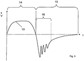
- Fig. 3 shows a typical course of the flow (13) for patients with COPD diseases.
- the volume flow (13) in the inspiration phase (14) is greatly flattened and during the expiratory phase (15) occur in particular at a beginning of this phase significant disturbances.
- the disturbances lead to strong fluctuations in the volume flow and possibly even to a return flow.
- Marked in Fig. 3 is a blockade time (16), during which a detection of a measurement signal for generating a trigger signal and / or an evaluation of the measurement signal for providing the trigger signal and / or an output of the trigger signal and / or a function triggering due to a trigger signal is not performed. A malfunction of the device due to a falsely detected termination of the expiratory phase (15) is thus avoided, thereby ensuring a sufficiently long expiratory phase (15).
- the measurement signal can be evaluated directly or after filtering.
- Fig. 4 indicates a further course of the volume flow (13), in which the expiratory phase (15) has been extended.
- the blockage time (16) can be fixed. It is also possible to let the blockage time (16) be determined adaptively by the ventilator itself. The determination can be made on the basis of an analysis of the measured values, in which the periods of major disturbances are recorded.
- This type of device control can be used in assisted ventilation with background frequency (example: ST mode) for the adaptive control of the background frequency.
- controlled ventilation e.g., T-mode
- T-mode is possible by replacing a predetermined one by this adaptive expiratory time.
- An adaptive determination of the expiratory phase (15) can take place taking into account the following calculation methods, which can be implemented in the control program of the ventilator.
- Paw R ⁇ flow + 1 C ⁇ ⁇ flow
- Paw the expiratory pressure applied by the ventilator.
- R the airway resistance
- C the compliance (extensibility) of the lung.
- the time constant ⁇ may be known, for example, from a lung function measurement, or determined, for example, in the analysis phase of a TA mode.
- the volume VT can either be measured online per breath or as an average of several breaths.
- the device control allows switching to the subsequent inspiration only when no exhalation activity of the patient is detected more, the expiratory flow - after deduction of any existing leakage flow - has become zero.
- the generation of the trigger signal for the start of inspiration can for example be carried out such that the first or second time derivative of the volume flow (13) is detected. In particular, this is intended for a filtered signal evaluation.
- assisted ventilation With assisted ventilation, the trigger signal is suppressed if incorrect measurements are detected.
- assisted ventilation a release is made for the evaluation of the slope of the flow signal after the expiration of the minimum expiratory time. Typically, with a detected slope of the flow signal, it switches from 0 to inspiration.
Landscapes
- Health & Medical Sciences (AREA)
- Emergency Medicine (AREA)
- Pulmonology (AREA)
- Engineering & Computer Science (AREA)
- Anesthesiology (AREA)
- Biomedical Technology (AREA)
- Heart & Thoracic Surgery (AREA)
- Hematology (AREA)
- Life Sciences & Earth Sciences (AREA)
- Animal Behavior & Ethology (AREA)
- General Health & Medical Sciences (AREA)
- Public Health (AREA)
- Veterinary Medicine (AREA)
- Measurement Of The Respiration, Hearing Ability, Form, And Blood Characteristics Of Living Organisms (AREA)
Description
- Die Erfindung betrifft eine Vorrichtung zur Beatmung, die eine mit einer Steuerung verbundene Atemgaspumpe aufweist und bei der die Atemgaspumpe mit einem Patienteninterface verbindbar ist sowie bei der von der Steuerung während einer Exspirationsphase ein niedrigerer Atemgasdruck als während einer Inspirationsphase vorgegeben ist und bei der zur messtechnischen Erfassung mindestens eines Parameters des Atemgases mindestens ein Sensor an die Steuerung angeschlossen ist wobei die Steuerung eine Steuercharakteristik mit einer Mindestexspirationszeit aufweist.
- Insbesondere betrifft die Erfindung eine entsprechende Vorrichtung, bei der ein Beginn der Inspirationsphase von einem in Abhängigkeit vom messtechnisch erfassten Parameter generierten Triggersignal gesteuert ist.
- Mit derartigen Vorrichtungen ist es alternativ oder kumulativ möglich, eine Triggerung durch den Patienten über Druck oder Fluss, durchzuführen.
- Derartige Vorrichtungen können insbesondere im Zusammenhang mit Beatmungsgeräten zum Einsatz kommen, die für Patienten mit COPD-Erkrankungen verwendet werden. Bei derartigen Erkrankungen sind die Lungen der Patienten in der Regel stark geschädigt. Typische Krankheitsbilder sind Emphysem und chronisch obstruktive Bronchitis. Diese Erkrankungen führen zu Rückkopplungen auf messtechnisch erfassbare Signale und beeinflussen insbesondere den Volumenfluß des Atemgases. Die Störungen machen sich in unregelmäßigen Signalverläufen bei einer messtechnischen Erfassung von Atemgasparametern bemerkbar.
- Bei Beatmungsgeräten, die in Abhängigkeit von messtechnisch erfassten Signalen gesteuert werden, führen diese Störungen zu Fehlfunktionen, die therapeutisch sinnvolle Inspirationszeiten und Exspirationszeiten verändern und insbesondere zu einer ungewollten Verkürzung von Exspirationszeiten führen.-
- Aus der
EP 1 586 343 A1 ist bereits ein Verfahren und eine Vorrichtung zur kontrollierten oder mandatorischen Beatmung bekannt. Die Atemarbeit des Patienten wird hierbei ständig vom Beatmungsgerät übernommen. Das Beatmungsgerät gibt die zeitliche Dauer der Inspirationsphasen und der Exspirationsphasen vor. - In der
WO 02/28460 A1 EP 0 521 314 A1 werden bereits Verfahren zur Durchführung einer Beatmung in Abhängigkeit von Triggersignalen beschrieben. Insbesondere erfolgt eine Umschaltung von der Inspirationsphase in die Exspirationsphase in Abhängigkeit von Triggersignalen, die durch eine sensorische Erfassung von eigenen Atembemühungen des Patienten bereitgestellt werden. - Aufgabe der vorliegenden Erfindung ist es, eine Vorrichtung zur unterstützenden Beatmung, der einleitend genannten Art derart zu konstruieren, dass eine fehlertolerante Gerätesteuerung unterstützt wird. Diese Vorrichtung ist in Anspruch 1 definiert. Insbesondere ist bei dieser Vorrichtung, bei der Beginn der Inspirationsphase von einem in Abhängigkeit vom messtechnisch erfassten Parameter generierten Triggersignal gesteuert wird, daran gedacht, dass die Steuerung mit einer Triggersignalunterdrückung versehen ist, die eine Druckerhöhung für eine vorgebbare Blockadezeit sperrt, die mit einer exspiratorischen Druckabsenkung beginnt.
- Erfindungsgemäß wird berücksichtigt, dass zu einem Beginn der Exspiration, die mit einem vergleichsweise großen Volumenstrom an Atemgas im Zusammenhang steht, starke Störungen des Flowsignales vorliegen. Dieses Signal wird typischerweise Messtechnisch erfasst, um bei einer druckgesteuerten Beatmung nach einer entsprechenden gerätetechnischen Signalauswertung zur Generierung eines Triggersignals verwendet zu werden. Zum Ende der Exspirationszeit liegt ein vergleichsweise kleiner Volumenstrom vor und das Signal ist deutlich weniger gestört. Bei Patienten mit COPD-Erkrankungen tritt das zusätzliche Problem auf, das im Vergleich zu anderen Erkrankungen der Lunge zu einem Exspirationsbeginn lediglich ein geringer Volumenstrom detektierbar ist, der eine aufwendige Triggersignalerkennung im Beatmungsgerät erfordert.
- Durch die erfindungsgemäße Triggersignalunterdrückung während der Zeit der höchsten Störwahrscheinlichkeit wird eine ungewollte Verkürzung der Exspiration vermieden. Die Blockadezeit vermeidet die Verwendung unempfindlicher Signalauswertungen, da die stark gestörten Signale der Auswertung nicht zugeführt werden und im Anschluss an das Auftreten der stark gestörten Signale eine empfindliche Signalauswertung realisierbar ist.
- Eine vorteilhafte Gerätesteuerung kann dadurch erfolgen, dass das Triggersignal durch Auswertung eines Signales eines Volumenstromes an Atemgas ermittelt wird.
- Eine Erkennung eines Endes der Exspirationsphase kann dadurch erfolgen, dass ein Vorzeichenwechsel einer ersten zeitlichen Ableitung des Flowsignals zur Triggerauslösung verwendet wird.
- Alternativ ist auch daran gedacht, dass ein Vorzeichenwechsel einer zweiten zeitlichen Ableitung des Flowsignals zur Triggerauslösung verwendet wird.
- Gemäß einer vereinfachten Ausführungsvariante ist es möglich, dass die Blockadezeit fest vorgegeben ist.
- Ein verbesserter Gerätekomfort wird dadurch bereitgestellt, dass die Blockadezeit adaptiv von einer Messsignalauswertung ermittelt wird.
- In den Zeichnungen sind Ausführungsbeispiele der Erfindung schematisch dargestellt. Es zeigen:
- Fig. 1:
- eine schematische Darstellung eines Beatmungsgerätes mit angeschlossenem Patienteninterface,
- Fig. 2:
- einen Verlauf eines Volumenstromes an Atemgas ohne Störungen,
- Fig. 3:
- einen gestörten Verlauf des Volumenstromes an Atemgas bei COPD-Erkrankungen und
- Fig. 4:
- eine weitere Darstellung eines Volumenstromes mit verlängerter Exspirationszeit.
-
Fig. 1 zeigt den grundsätzlichen Aufbau einer Vorrichtung zur Beatmung. Im Bereich eines Gerätegehäuses (1) mit Bedienfeld (2) sowie Anzeige (3) ist in einem Geräteinnenraum eine Atemgaspumpe angeordnet. Über eine Kopplung (4) wird ein Atemgasschlauch (5) angeschlossen. Entlang des Atemgasschlauches (5) kann ein zusätzlicher Druckmessschlauch (6) verlaufen, der über einen Druckeingangsstutzen (7) mit dem Gerätegehäuse (1) verbindbar ist. Zur Ermöglichung einer Datenübertragung weist das Gerätegehäuse (1) eine Schnittstelle (8) auf. - An der dem Gerätegehäuse (1) abgewandten Seite des Beatmungsschlauches (5) befindet sich eine Schlauchankopplung (9) zur Verbindung des Beatmungsschlauches (5) mit der Atemmaske (10).
-
Fig. 1 zeigt darüber hinaus eine Atemmaske (10), die als Nasenmaske oder als Vollgesichtsmaske ausgebildet sein kann. Eine Fixierung im Bereich des Kopfes eines Patienten kann über eine Kopfhaube (11) erfolgen. - Die Atemmaske (10) weist als Schlauchanschluss (13) einen gebogenen Kugelgelenkanschluss (12) auf, der über die Schlauchankopplung (9) mit dem Beatmungsschlauch (5) verbunden wird.
-
Fig. 2 zeigt einen Verlauf eines Volumentstromes (13), der in eine Inspirationsphase (14) und eine Exspirationsphase (15) unterteilt ist. Während der Inspirationsphase (14) stellt das Beatmungsgerät einen erhöhten und während der Exspirationsphase (15) einen verminderten Druck bereit. -
Fig. 3 zeigt einen typischen Verlauf des Volumenstromes (13) für Patienten mit COPD-Erkrankungen. Der Volumenstrom (13) in der Inspirationsphase (14) ist stark abgeflacht und während der Exspirationsphase (15) treten insbesondere zu einem Beginn dieser Phase erhebliche Störungen auf. Die Störungen führen zu starken Schwankungen des Volumenstromes sowie gegebenenfalls sogar zu einem Rückflow. - Eingezeichnet in
Fig. 3 ist eine Blockadezeit (16), während der eine Erfassung eines Messsignales zur Generierung eines Triggersignales und/oder eine Auswertung des Messsignales zur Bereitstellung des Triggersignales und/oder eine Ausgabe des Triggersignales und/oder eine Funktionsauslösung aufgrund eines Triggersignales nicht durchgeführt wird. Eine Fehlfunktion des Gerätes aufgrund einer fälschlich detektierten Beendigung der Exspirationsphase (15) wird somit vermieden und hierdurch für eine ausreichend lange Exspirationsphase (15) gesorgt. Das Messsignal kann direkt oder nach einer Filterung ausgewertet werden. -
Fig. 4 zeigt einen weiteren Verlauf des Volumenstromes (13) an, bei dem die Exspirationsphase (15) verlängert wurde. - Hinsichtlich der zeitlichen Vorgabe der Blockadezeit (16) sind unterschiedliche Varianten möglich. Zum einen kann die Blockadezeit (16) fest eingestellt sein. Ebenfalls ist es möglich, die Blockadezeit (16) adaptiv vom Beatmungsgerät selbst ermitteln zu lassen. Die Ermittlung kann aufgrund einer Analyse der Messwerte erfolgen, bei der die Zeiträume großer Störungen erfasst werden. Alternativ oder ergänzend zur vorstehend erläuterten Triggerblockade ist es auch möglich, die Exspirationsphase zeitlich gesteuert zu verlängern. Gemäß einem Ausführungsbeispiel ist daran gedacht, jede fünfte Exspirationsphase gegenüber einer Grundlänge um etwa 20% zu verlängern. Ebenfalls ist es alternativ oder ergänzend möglich, die Exspirationszeit in Abhängigkeit vom inspirierten Volumen an Atemgas zu verlängern. Ein größeres Volumen an Atemgas während der Inspirationszeit führt somit zu einer entsprechenden Verlängerung der Exspirationszeit.
- Diese Art der Gerätesteuerung kann bei einer assistierten Beatmung mit Hintergrundfrequenz (Beispiel: ST-Modus) für die adaptive Steuerung der Hintergrundfrequenz zur Anwendung kommen. Alternativ ist eine kontrollierte Beatmung (z.B. T-Modus) möglich, indem eine fest vorgegebene durch diese adaptive Exspirationszeit ersetzt wird.
- Eine adaptive Ermittlung der Exspirationsphase (15) kann unter Berücksichtigung der nachfolgenden Berechnungsmethoden erfolgen, die im Steuerprogramm des Beatmungsgerätes implementierbar sind.
- Für die zumeist passive Exspiration eines Patienten gilt die Bewegungsgleichung (Equation of Motion) der Beatmung:

- Nach Lösung dieser Differentialgleichung ergibt sich für den zeitlichen Verlauf des exspiratorischen Volumens:

- Wobei τ = R · C gilt.
- Wenn beim Patienten allerhöchstens z.B. Vsoll = 10ml am Ende der Exspiration in seiner Lunge verbleiben dürfen, dann ergibt sich für Texsp:

- Die Zeitkonstante τ kann z.B. aus einer Lungenfunktionsmessung bekannt sein, oder z.B. in der Analysephase eines TA-Modus bestimmt worden sein.
- Das Volumen VT kann entweder online pro Atemzug gemessen werden oder sich als Durchschnittsbetrachtung aus mehreren Atemzügen ergeben.
- Gemäß einer weiteren Ausführungsform ist es möglich, die Steuerung der Exspirationszeit bei der assistierten Beatmung mit Hintergrundfrequenz oder bei der kontrollierten Beatmung direkt auf Basis des Flusssignals während der Exspiration zu steuern. Die Gerätesteuerung erlaubt erst dann ein Umschalten in die nachfolgende Inspiration, wenn keine Ausatemaktivität des Patienten mehr erkannt wird, der Exspirationsfluss - nach Abzug eines ggf. vorhandenen Leckageflusses - zu Null geworden ist.
- Bei der gerätetechnischen Realisierung kann die Generierung des Triggersignales für den Inspirationsbeginn beispielsweise derart erfolgen, dass die erste oder zweite zeitliche Ableitung des Volumenstromes (13) erfasst wird. Insbesondere ist hierbei an eine gefilterte Signalauswertung gedacht.
- Bei einer unterstützten Beatmung erfolgt bei detektierten Fehlmessungen eine Unterdrückung des Triggersignales. Bei der assistierten Beatmung erfolgt eine Freigabe für die Auswertung der Steigung des Flowsignals nach Ablauf der Mindestexspirationszeit. Typischerweise wird bei einer erkannten Steigung des Flowsignals von 0 in die Inspiration umgeschaltet.
Claims (3)
- Vorrichtung zur unterstützenden Beatmung, die eine mit einer Steuerung verbundene Atemgaspumpe aufweist und bei der die Atemgaspumpe mit einem Patienteninterface verbindbar ist, sowie bei der von der Steuerung während einer Exspirationsphase ein niedrigerer Atemgasdruck als während einer Inspirationsphase vorgegeben ist und bei der zur messtechnischen Erfassung mindestens eines Parameters des Atemgases mindestens ein Sensor an die Steuerung angeschlossen ist, dadurch gekennzeichnet, dass die Steuerung eine Steuercharakteristik mit einer Mindestexspirationszeit aufweist,
die eine Triggerblockadezeit ist, während der ein registriertes patientenseitiges Signal, auf dessen Basis eine Umschaltung in die Inspiration möglich ist, nicht berücksichtigt wird und
dass die Steuerung mit einer Triggersignalunterdrückung versehen ist, die eine Druckerhöhung für die vorgebbare Triggerblockadezeit sperrt, die mit einer exspiratorischen Druckabsenkung beginnt, und
dass die die Mindestexspirationszeit um die Zeitdauer bis zum Auftreten eines den Atemfluss der Exspiration oder das Atemzugvolumen der Inspiration repräsentierenden Signals, das anzeigt, dass der Exspirationsvorgang des Patienten abgeschlossen ist, verlängert wird, falls nach Ablauf der Mindestexspirationszeit angezeigt wird, dass der Exspirationsvorgang nicht abgeschlossen ist. - Vorrichtung nach Anspruch 1, dadurch gekennzeichnet, dass als Atemgas-Parameter der Fluss oder der Druck oder das Volumen an Atemgas erfasst wird und Steuervorgänge auf Basis des sensorisch erfassten Parameters erfolgen.
- Vorrichtung nach Anspruch 1 oder 2, dadurch gekennzeichnet, dass die Steuerung den Atemgasdruck in der Exspiration erhöht, wenn ein den Atemfluss oder das Atemzugvolumen repräsentierendes Signal anzeigt, dass der Exspirationsvorgang des Patienten nicht beendet ist.
Applications Claiming Priority (1)
| Application Number | Priority Date | Filing Date | Title |
|---|---|---|---|
| DE102008038267A DE102008038267A1 (de) | 2008-08-11 | 2008-08-11 | Verfahren und Vorrichtung zur Beatmung |
Publications (3)
| Publication Number | Publication Date |
|---|---|
| EP2153857A2 EP2153857A2 (de) | 2010-02-17 |
| EP2153857A3 EP2153857A3 (de) | 2012-08-01 |
| EP2153857B1 true EP2153857B1 (de) | 2018-01-17 |
Family
ID=41291833
Family Applications (1)
| Application Number | Title | Priority Date | Filing Date |
|---|---|---|---|
| EP09400038.7A Active EP2153857B1 (de) | 2008-08-11 | 2009-08-10 | Vorrichtung zur Beatmung |
Country Status (2)
| Country | Link |
|---|---|
| EP (1) | EP2153857B1 (de) |
| DE (1) | DE102008038267A1 (de) |
Families Citing this family (3)
| Publication number | Priority date | Publication date | Assignee | Title |
|---|---|---|---|---|
| US10773037B2 (en) * | 2016-06-23 | 2020-09-15 | Loewenstein Medical Technology S.A. | Ventilator and method |
| CN113952565B (zh) * | 2021-10-22 | 2023-10-31 | 广西开蒙医疗科技有限公司 | 气路流量与压力计算方法、系统 |
| CN117531079A (zh) * | 2023-11-07 | 2024-02-09 | 可孚医疗科技股份有限公司 | 呼吸机及其压力调整方法、系统 |
Family Cites Families (4)
| Publication number | Priority date | Publication date | Assignee | Title |
|---|---|---|---|---|
| DE4122069A1 (de) * | 1991-07-04 | 1993-01-07 | Draegerwerk Ag | Verfahren zur erkennung der atemphasen eines patienten bei assistierenden beatmungsverfahren |
| US6626175B2 (en) * | 2000-10-06 | 2003-09-30 | Respironics, Inc. | Medical ventilator triggering and cycling method and mechanism |
| DE10212497A1 (de) * | 2002-03-21 | 2003-10-16 | Weinmann G Geraete Med | Verfahren zur Steuerung eines Beatmungsgerätes sowie Vorrichtung zur Beatmung |
| DE102004018029A1 (de) * | 2004-04-14 | 2005-11-03 | Weinmann Geräte für Medizin GmbH + Co. KG | Vorrichtung zur Beatmung sowie Verfahren zur Steuerung eines Beatmungsgerätes |
-
2008
- 2008-08-11 DE DE102008038267A patent/DE102008038267A1/de not_active Ceased
-
2009
- 2009-08-10 EP EP09400038.7A patent/EP2153857B1/de active Active
Non-Patent Citations (1)
| Title |
|---|
| None * |
Also Published As
| Publication number | Publication date |
|---|---|
| EP2153857A2 (de) | 2010-02-17 |
| DE102008038267A1 (de) | 2010-02-18 |
| EP2153857A3 (de) | 2012-08-01 |
Similar Documents
| Publication | Publication Date | Title |
|---|---|---|
| DE102004006396B4 (de) | Vorrichtung zur Beatmung sowie Verfahren zur Steuerung eines Beatmungsgerätes | |
| DE69736808T2 (de) | Determination einer leckluftströmung | |
| DE10217762C1 (de) | Verfahren und Vorrichtung zur Steuerung der Atemgasversorgung | |
| DE19808543C2 (de) | Verfahren zur Bestimmung der mechanischen Eigenschaften des respiratorischen Systems eines Patienten und Vorrichtung zur Durchführung des Verfahrens | |
| EP1727580B1 (de) | Verfahren zur steuerung eines bilevel-geräts sowie bilevel-gerät | |
| EP1605999A1 (de) | Verfahren und vorrichtung zur erkennung von leckagen bei einrichtungen zum zuführen von atemgasen | |
| DE102008002820A1 (de) | Verfahren und System zur Erfassung eines Beatmungstubusverschlusses | |
| DE102007006689A1 (de) | Vorrichtung und Verfahren zur Obstruktionserkennung während Apnoephasen durch eine zusätzliche Druckstufe | |
| DE102007035549A1 (de) | Verfahren und Gerät zur Atmungsüberwachung | |
| DE102006052572B3 (de) | Verfahren und Beatmungseinrichtung zur druckunterstützten Spontanatmung | |
| DE102007011924A1 (de) | Verfahren und Vorrichtung zur Steuerung eines Beatmungsgerätes | |
| DE102016012824A1 (de) | Verfahren und Vorrichtung zum adaptiven Regeln eines positiv endexspiratorischen Drucks (PEEP) | |
| DE102015015440A1 (de) | Anästhesiebeatmungsvorrichtung zur automatischen Beatmung eines Patienten | |
| EP2153857B1 (de) | Vorrichtung zur Beatmung | |
| DE102007033047A1 (de) | Vorrichtung und Verfahren zur Erkennung von obstruktiven Ereignissen | |
| DE102018003026A1 (de) | Beatmungsvorrichtung mit einem Sicherheitsventil | |
| DE10212497A1 (de) | Verfahren zur Steuerung eines Beatmungsgerätes sowie Vorrichtung zur Beatmung | |
| EP1371384B1 (de) | Vorrichtung zur Beatmung mit Steuerung | |
| DE102018003027A1 (de) | Beatmungsvorrichtung | |
| DE102019006480A1 (de) | Verfahren und Signalverarbeitung zum Ermitteln der Atmungsaktivität eines Patienten | |
| DE102022106326A1 (de) | Verfahren und Vorrichtung zur näherungsweisen Bestimmung von Herzschlag-Zeitpunkten | |
| DE102019007717B3 (de) | Verfahren und Signalverarbeitungseinheit zum Ermitteln der Atmungsaktivität eines Patienten | |
| DE602004003409T2 (de) | Gerät zur Bestimmung von Absaugdurchfluss und Absaugzeit und zur Absaugung von Totraum | |
| EP3964253B1 (de) | Computerprogramm und vorrichtung zur automatischen festlegung der sollfrequenz eines beatmungsgeräts | |
| EP1586343B1 (de) | Vorrichtung zur Beatmung sowie Verfahren zur Steuerung eines Beatmungsgerätes |
Legal Events
| Date | Code | Title | Description |
|---|---|---|---|
| PUAI | Public reference made under article 153(3) epc to a published international application that has entered the european phase |
Free format text: ORIGINAL CODE: 0009012 |
|
| AK | Designated contracting states |
Kind code of ref document: A2 Designated state(s): AT BE BG CH CY CZ DE DK EE ES FI FR GB GR HR HU IE IS IT LI LT LU LV MC MK MT NL NO PL PT RO SE SI SK SM TR |
|
| AX | Request for extension of the european patent |
Extension state: AL BA RS |
|
| PUAL | Search report despatched |
Free format text: ORIGINAL CODE: 0009013 |
|
| AK | Designated contracting states |
Kind code of ref document: A3 Designated state(s): AT BE BG CH CY CZ DE DK EE ES FI FR GB GR HR HU IE IS IT LI LT LU LV MC MK MT NL NO PL PT RO SE SI SK SM TR |
|
| AX | Request for extension of the european patent |
Extension state: AL BA RS |
|
| RIC1 | Information provided on ipc code assigned before grant |
Ipc: A61M 16/00 20060101AFI20120622BHEP |
|
| 17P | Request for examination filed |
Effective date: 20121027 |
|
| 17Q | First examination report despatched |
Effective date: 20130514 |
|
| RAP1 | Party data changed (applicant data changed or rights of an application transferred) |
Owner name: LOEWENSTEIN MEDICAL TECHNOLOGY S.A. |
|
| GRAP | Despatch of communication of intention to grant a patent |
Free format text: ORIGINAL CODE: EPIDOSNIGR1 |
|
| INTG | Intention to grant announced |
Effective date: 20171019 |
|
| GRAS | Grant fee paid |
Free format text: ORIGINAL CODE: EPIDOSNIGR3 |
|
| GRAA | (expected) grant |
Free format text: ORIGINAL CODE: 0009210 |
|
| AK | Designated contracting states |
Kind code of ref document: B1 Designated state(s): AT BE BG CH CY CZ DE DK EE ES FI FR GB GR HR HU IE IS IT LI LT LU LV MC MK MT NL NO PL PT RO SE SI SK SM TR |
|
| REG | Reference to a national code |
Ref country code: GB Ref legal event code: FG4D Free format text: NOT ENGLISH |
|
| REG | Reference to a national code |
Ref country code: CH Ref legal event code: EP |
|
| REG | Reference to a national code |
Ref country code: IE Ref legal event code: FG4D Free format text: LANGUAGE OF EP DOCUMENT: GERMAN |
|
| REG | Reference to a national code |
Ref country code: AT Ref legal event code: REF Ref document number: 963999 Country of ref document: AT Kind code of ref document: T Effective date: 20180215 |
|
| REG | Reference to a national code |
Ref country code: DE Ref legal event code: R096 Ref document number: 502009014680 Country of ref document: DE |
|
| REG | Reference to a national code |
Ref country code: NL Ref legal event code: MP Effective date: 20180117 |
|
| REG | Reference to a national code |
Ref country code: LT Ref legal event code: MG4D |
|
| PG25 | Lapsed in a contracting state [announced via postgrant information from national office to epo] |
Ref country code: NL Free format text: LAPSE BECAUSE OF FAILURE TO SUBMIT A TRANSLATION OF THE DESCRIPTION OR TO PAY THE FEE WITHIN THE PRESCRIBED TIME-LIMIT Effective date: 20180117 |
|
| PG25 | Lapsed in a contracting state [announced via postgrant information from national office to epo] |
Ref country code: HR Free format text: LAPSE BECAUSE OF FAILURE TO SUBMIT A TRANSLATION OF THE DESCRIPTION OR TO PAY THE FEE WITHIN THE PRESCRIBED TIME-LIMIT Effective date: 20180117 Ref country code: CY Free format text: LAPSE BECAUSE OF FAILURE TO SUBMIT A TRANSLATION OF THE DESCRIPTION OR TO PAY THE FEE WITHIN THE PRESCRIBED TIME-LIMIT Effective date: 20180117 Ref country code: LT Free format text: LAPSE BECAUSE OF FAILURE TO SUBMIT A TRANSLATION OF THE DESCRIPTION OR TO PAY THE FEE WITHIN THE PRESCRIBED TIME-LIMIT Effective date: 20180117 Ref country code: ES Free format text: LAPSE BECAUSE OF FAILURE TO SUBMIT A TRANSLATION OF THE DESCRIPTION OR TO PAY THE FEE WITHIN THE PRESCRIBED TIME-LIMIT Effective date: 20180117 Ref country code: NO Free format text: LAPSE BECAUSE OF FAILURE TO SUBMIT A TRANSLATION OF THE DESCRIPTION OR TO PAY THE FEE WITHIN THE PRESCRIBED TIME-LIMIT Effective date: 20180417 Ref country code: FI Free format text: LAPSE BECAUSE OF FAILURE TO SUBMIT A TRANSLATION OF THE DESCRIPTION OR TO PAY THE FEE WITHIN THE PRESCRIBED TIME-LIMIT Effective date: 20180117 |
|
| REG | Reference to a national code |
Ref country code: FR Ref legal event code: PLFP Year of fee payment: 10 |
|
| PG25 | Lapsed in a contracting state [announced via postgrant information from national office to epo] |
Ref country code: LV Free format text: LAPSE BECAUSE OF FAILURE TO SUBMIT A TRANSLATION OF THE DESCRIPTION OR TO PAY THE FEE WITHIN THE PRESCRIBED TIME-LIMIT Effective date: 20180117 Ref country code: PL Free format text: LAPSE BECAUSE OF FAILURE TO SUBMIT A TRANSLATION OF THE DESCRIPTION OR TO PAY THE FEE WITHIN THE PRESCRIBED TIME-LIMIT Effective date: 20180117 Ref country code: GR Free format text: LAPSE BECAUSE OF FAILURE TO SUBMIT A TRANSLATION OF THE DESCRIPTION OR TO PAY THE FEE WITHIN THE PRESCRIBED TIME-LIMIT Effective date: 20180418 Ref country code: BG Free format text: LAPSE BECAUSE OF FAILURE TO SUBMIT A TRANSLATION OF THE DESCRIPTION OR TO PAY THE FEE WITHIN THE PRESCRIBED TIME-LIMIT Effective date: 20180417 Ref country code: IS Free format text: LAPSE BECAUSE OF FAILURE TO SUBMIT A TRANSLATION OF THE DESCRIPTION OR TO PAY THE FEE WITHIN THE PRESCRIBED TIME-LIMIT Effective date: 20180517 Ref country code: SE Free format text: LAPSE BECAUSE OF FAILURE TO SUBMIT A TRANSLATION OF THE DESCRIPTION OR TO PAY THE FEE WITHIN THE PRESCRIBED TIME-LIMIT Effective date: 20180117 |
|
| PG25 | Lapsed in a contracting state [announced via postgrant information from national office to epo] |
Ref country code: MT Free format text: LAPSE BECAUSE OF FAILURE TO SUBMIT A TRANSLATION OF THE DESCRIPTION OR TO PAY THE FEE WITHIN THE PRESCRIBED TIME-LIMIT Effective date: 20180117 |
|
| REG | Reference to a national code |
Ref country code: DE Ref legal event code: R097 Ref document number: 502009014680 Country of ref document: DE |
|
| PG25 | Lapsed in a contracting state [announced via postgrant information from national office to epo] |
Ref country code: RO Free format text: LAPSE BECAUSE OF FAILURE TO SUBMIT A TRANSLATION OF THE DESCRIPTION OR TO PAY THE FEE WITHIN THE PRESCRIBED TIME-LIMIT Effective date: 20180117 Ref country code: EE Free format text: LAPSE BECAUSE OF FAILURE TO SUBMIT A TRANSLATION OF THE DESCRIPTION OR TO PAY THE FEE WITHIN THE PRESCRIBED TIME-LIMIT Effective date: 20180117 |
|
| PLBE | No opposition filed within time limit |
Free format text: ORIGINAL CODE: 0009261 |
|
| STAA | Information on the status of an ep patent application or granted ep patent |
Free format text: STATUS: NO OPPOSITION FILED WITHIN TIME LIMIT |
|
| PG25 | Lapsed in a contracting state [announced via postgrant information from national office to epo] |
Ref country code: SM Free format text: LAPSE BECAUSE OF FAILURE TO SUBMIT A TRANSLATION OF THE DESCRIPTION OR TO PAY THE FEE WITHIN THE PRESCRIBED TIME-LIMIT Effective date: 20180117 Ref country code: DK Free format text: LAPSE BECAUSE OF FAILURE TO SUBMIT A TRANSLATION OF THE DESCRIPTION OR TO PAY THE FEE WITHIN THE PRESCRIBED TIME-LIMIT Effective date: 20180117 Ref country code: CZ Free format text: LAPSE BECAUSE OF FAILURE TO SUBMIT A TRANSLATION OF THE DESCRIPTION OR TO PAY THE FEE WITHIN THE PRESCRIBED TIME-LIMIT Effective date: 20180117 Ref country code: SK Free format text: LAPSE BECAUSE OF FAILURE TO SUBMIT A TRANSLATION OF THE DESCRIPTION OR TO PAY THE FEE WITHIN THE PRESCRIBED TIME-LIMIT Effective date: 20180117 |
|
| 26N | No opposition filed |
Effective date: 20181018 |
|
| PG25 | Lapsed in a contracting state [announced via postgrant information from national office to epo] |
Ref country code: SI Free format text: LAPSE BECAUSE OF FAILURE TO SUBMIT A TRANSLATION OF THE DESCRIPTION OR TO PAY THE FEE WITHIN THE PRESCRIBED TIME-LIMIT Effective date: 20180117 |
|
| PG25 | Lapsed in a contracting state [announced via postgrant information from national office to epo] |
Ref country code: MC Free format text: LAPSE BECAUSE OF FAILURE TO SUBMIT A TRANSLATION OF THE DESCRIPTION OR TO PAY THE FEE WITHIN THE PRESCRIBED TIME-LIMIT Effective date: 20180117 |
|
| PG25 | Lapsed in a contracting state [announced via postgrant information from national office to epo] |
Ref country code: LU Free format text: LAPSE BECAUSE OF NON-PAYMENT OF DUE FEES Effective date: 20180810 |
|
| REG | Reference to a national code |
Ref country code: BE Ref legal event code: MM Effective date: 20180831 |
|
| REG | Reference to a national code |
Ref country code: IE Ref legal event code: MM4A |
|
| PG25 | Lapsed in a contracting state [announced via postgrant information from national office to epo] |
Ref country code: IE Free format text: LAPSE BECAUSE OF NON-PAYMENT OF DUE FEES Effective date: 20180810 |
|
| PG25 | Lapsed in a contracting state [announced via postgrant information from national office to epo] |
Ref country code: BE Free format text: LAPSE BECAUSE OF NON-PAYMENT OF DUE FEES Effective date: 20180831 |
|
| PG25 | Lapsed in a contracting state [announced via postgrant information from national office to epo] |
Ref country code: TR Free format text: LAPSE BECAUSE OF FAILURE TO SUBMIT A TRANSLATION OF THE DESCRIPTION OR TO PAY THE FEE WITHIN THE PRESCRIBED TIME-LIMIT Effective date: 20180117 |
|
| PG25 | Lapsed in a contracting state [announced via postgrant information from national office to epo] |
Ref country code: PT Free format text: LAPSE BECAUSE OF FAILURE TO SUBMIT A TRANSLATION OF THE DESCRIPTION OR TO PAY THE FEE WITHIN THE PRESCRIBED TIME-LIMIT Effective date: 20180117 Ref country code: HU Free format text: LAPSE BECAUSE OF FAILURE TO SUBMIT A TRANSLATION OF THE DESCRIPTION OR TO PAY THE FEE WITHIN THE PRESCRIBED TIME-LIMIT; INVALID AB INITIO Effective date: 20090810 |
|
| PG25 | Lapsed in a contracting state [announced via postgrant information from national office to epo] |
Ref country code: MK Free format text: LAPSE BECAUSE OF NON-PAYMENT OF DUE FEES Effective date: 20180117 |
|
| P01 | Opt-out of the competence of the unified patent court (upc) registered |
Effective date: 20230524 |
|
| PGFP | Annual fee paid to national office [announced via postgrant information from national office to epo] |
Ref country code: DE Payment date: 20250819 Year of fee payment: 17 |
|
| PGFP | Annual fee paid to national office [announced via postgrant information from national office to epo] |
Ref country code: IT Payment date: 20250829 Year of fee payment: 17 |
|
| PGFP | Annual fee paid to national office [announced via postgrant information from national office to epo] |
Ref country code: GB Payment date: 20250822 Year of fee payment: 17 |
|
| PGFP | Annual fee paid to national office [announced via postgrant information from national office to epo] |
Ref country code: AT Payment date: 20250819 Year of fee payment: 17 Ref country code: FR Payment date: 20250821 Year of fee payment: 17 |
|
| PGFP | Annual fee paid to national office [announced via postgrant information from national office to epo] |
Ref country code: CH Payment date: 20250901 Year of fee payment: 17 |