EP2153885A1 - Dispositif moussant pour faire mousser une substance liquide - Google Patents
Dispositif moussant pour faire mousser une substance liquide Download PDFInfo
- Publication number
- EP2153885A1 EP2153885A1 EP08162361A EP08162361A EP2153885A1 EP 2153885 A1 EP2153885 A1 EP 2153885A1 EP 08162361 A EP08162361 A EP 08162361A EP 08162361 A EP08162361 A EP 08162361A EP 2153885 A1 EP2153885 A1 EP 2153885A1
- Authority
- EP
- European Patent Office
- Prior art keywords
- foaming
- foaming body
- liquid substance
- tool
- holes
- Prior art date
- Legal status (The legal status is an assumption and is not a legal conclusion. Google has not performed a legal analysis and makes no representation as to the accuracy of the status listed.)
- Ceased
Links
- 238000005187 foaming Methods 0.000 title claims abstract description 321
- 239000007788 liquid Substances 0.000 title claims abstract description 61
- 239000000126 substance Substances 0.000 title claims abstract description 60
- 239000007787 solid Substances 0.000 claims abstract description 31
- 238000000034 method Methods 0.000 claims description 5
- 235000013336 milk Nutrition 0.000 claims description 4
- 239000008267 milk Substances 0.000 claims description 4
- 210000004080 milk Anatomy 0.000 claims description 4
- 239000000463 material Substances 0.000 description 11
- 239000006260 foam Substances 0.000 description 6
- 229920001343 polytetrafluoroethylene Polymers 0.000 description 4
- 239000004810 polytetrafluoroethylene Substances 0.000 description 4
- RYGMFSIKBFXOCR-UHFFFAOYSA-N Copper Chemical compound [Cu] RYGMFSIKBFXOCR-UHFFFAOYSA-N 0.000 description 3
- 229910052782 aluminium Inorganic materials 0.000 description 3
- XAGFODPZIPBFFR-UHFFFAOYSA-N aluminium Chemical compound [Al] XAGFODPZIPBFFR-UHFFFAOYSA-N 0.000 description 3
- 229910052802 copper Inorganic materials 0.000 description 3
- 239000010949 copper Substances 0.000 description 3
- 230000008878 coupling Effects 0.000 description 3
- 238000010168 coupling process Methods 0.000 description 3
- 238000005859 coupling reaction Methods 0.000 description 3
- 238000004519 manufacturing process Methods 0.000 description 3
- 229910052751 metal Inorganic materials 0.000 description 3
- 239000002184 metal Substances 0.000 description 3
- 150000002739 metals Chemical class 0.000 description 3
- 229910001220 stainless steel Inorganic materials 0.000 description 3
- 239000010935 stainless steel Substances 0.000 description 3
- QCVGEOXPDFCNHA-UHFFFAOYSA-N 5,5-dimethyl-2,4-dioxo-1,3-oxazolidine-3-carboxamide Chemical compound CC1(C)OC(=O)N(C(N)=O)C1=O QCVGEOXPDFCNHA-UHFFFAOYSA-N 0.000 description 2
- 102000002322 Egg Proteins Human genes 0.000 description 2
- 108010000912 Egg Proteins Proteins 0.000 description 2
- 239000006071 cream Substances 0.000 description 2
- 230000000694 effects Effects 0.000 description 2
- 235000014103 egg white Nutrition 0.000 description 2
- 210000000969 egg white Anatomy 0.000 description 2
- 239000002103 nanocoating Substances 0.000 description 2
- 239000004033 plastic Substances 0.000 description 2
- 229920003023 plastic Polymers 0.000 description 2
- -1 polytetrafluoroethylene Polymers 0.000 description 2
- 230000003321 amplification Effects 0.000 description 1
- 230000000903 blocking effect Effects 0.000 description 1
- 238000004140 cleaning Methods 0.000 description 1
- 239000003086 colorant Substances 0.000 description 1
- 230000002301 combined effect Effects 0.000 description 1
- 230000005611 electricity Effects 0.000 description 1
- 238000009776 industrial production Methods 0.000 description 1
- 230000003993 interaction Effects 0.000 description 1
- 239000000203 mixture Substances 0.000 description 1
- 238000003199 nucleic acid amplification method Methods 0.000 description 1
- 230000002093 peripheral effect Effects 0.000 description 1
Images


Classifications
-
- A—HUMAN NECESSITIES
- A47—FURNITURE; DOMESTIC ARTICLES OR APPLIANCES; COFFEE MILLS; SPICE MILLS; SUCTION CLEANERS IN GENERAL
- A47J—KITCHEN EQUIPMENT; COFFEE MILLS; SPICE MILLS; APPARATUS FOR MAKING BEVERAGES
- A47J43/00—Implements for preparing or holding food, not provided for in other groups of this subclass
- A47J43/04—Machines for domestic use not covered elsewhere, e.g. for grinding, mixing, stirring, kneading, emulsifying, whipping or beating foodstuffs, e.g. power-driven
- A47J43/07—Parts or details, e.g. mixing tools, whipping tools
- A47J43/0705—Parts or details, e.g. mixing tools, whipping tools for machines with tools driven from the upper side
- A47J43/0711—Parts or details, e.g. mixing tools, whipping tools for machines with tools driven from the upper side mixing, whipping or cutting tools
-
- B—PERFORMING OPERATIONS; TRANSPORTING
- B01—PHYSICAL OR CHEMICAL PROCESSES OR APPARATUS IN GENERAL
- B01F—MIXING, e.g. DISSOLVING, EMULSIFYING OR DISPERSING
- B01F23/00—Mixing according to the phases to be mixed, e.g. dispersing or emulsifying
- B01F23/20—Mixing gases with liquids
- B01F23/23—Mixing gases with liquids by introducing gases into liquid media, e.g. for producing aerated liquids
- B01F23/235—Mixing gases with liquids by introducing gases into liquid media, e.g. for producing aerated liquids for making foam
- B01F23/2351—Mixing gases with liquids by introducing gases into liquid media, e.g. for producing aerated liquids for making foam using driven stirrers
-
- B—PERFORMING OPERATIONS; TRANSPORTING
- B01—PHYSICAL OR CHEMICAL PROCESSES OR APPARATUS IN GENERAL
- B01F—MIXING, e.g. DISSOLVING, EMULSIFYING OR DISPERSING
- B01F27/00—Mixers with rotary stirring devices in fixed receptacles; Kneaders
- B01F27/05—Stirrers
- B01F27/11—Stirrers characterised by the configuration of the stirrers
- B01F27/117—Stirrers provided with conical-shaped elements, e.g. funnel-shaped
- B01F27/1171—Stirrers provided with conical-shaped elements, e.g. funnel-shaped having holes in the surface
-
- B—PERFORMING OPERATIONS; TRANSPORTING
- B01—PHYSICAL OR CHEMICAL PROCESSES OR APPARATUS IN GENERAL
- B01F—MIXING, e.g. DISSOLVING, EMULSIFYING OR DISPERSING
- B01F27/00—Mixers with rotary stirring devices in fixed receptacles; Kneaders
- B01F27/05—Stirrers
- B01F27/11—Stirrers characterised by the configuration of the stirrers
- B01F27/19—Stirrers with two or more mixing elements mounted in sequence on the same axis
- B01F27/191—Stirrers with two or more mixing elements mounted in sequence on the same axis with similar elements
-
- B—PERFORMING OPERATIONS; TRANSPORTING
- B01—PHYSICAL OR CHEMICAL PROCESSES OR APPARATUS IN GENERAL
- B01F—MIXING, e.g. DISSOLVING, EMULSIFYING OR DISPERSING
- B01F27/00—Mixers with rotary stirring devices in fixed receptacles; Kneaders
- B01F27/80—Mixers with rotary stirring devices in fixed receptacles; Kneaders with stirrers rotating about a substantially vertical axis
- B01F27/94—Mixers with rotary stirring devices in fixed receptacles; Kneaders with stirrers rotating about a substantially vertical axis with rotary cylinders or cones
- B01F27/941—Mixers with rotary stirring devices in fixed receptacles; Kneaders with stirrers rotating about a substantially vertical axis with rotary cylinders or cones being hollow, perforated or having special stirring elements thereon
-
- A—HUMAN NECESSITIES
- A47—FURNITURE; DOMESTIC ARTICLES OR APPLIANCES; COFFEE MILLS; SPICE MILLS; SUCTION CLEANERS IN GENERAL
- A47J—KITCHEN EQUIPMENT; COFFEE MILLS; SPICE MILLS; APPARATUS FOR MAKING BEVERAGES
- A47J43/00—Implements for preparing or holding food, not provided for in other groups of this subclass
- A47J43/04—Machines for domestic use not covered elsewhere, e.g. for grinding, mixing, stirring, kneading, emulsifying, whipping or beating foodstuffs, e.g. power-driven
- A47J43/044—Machines for domestic use not covered elsewhere, e.g. for grinding, mixing, stirring, kneading, emulsifying, whipping or beating foodstuffs, e.g. power-driven with tools driven from the top side
- A47J2043/04409—Apparatus of hand held type
- A47J2043/04418—Apparatus of hand held type with housing extending perpendicular, e.g. horizontally, from the tool axis
-
- A—HUMAN NECESSITIES
- A47—FURNITURE; DOMESTIC ARTICLES OR APPLIANCES; COFFEE MILLS; SPICE MILLS; SUCTION CLEANERS IN GENERAL
- A47J—KITCHEN EQUIPMENT; COFFEE MILLS; SPICE MILLS; APPARATUS FOR MAKING BEVERAGES
- A47J43/00—Implements for preparing or holding food, not provided for in other groups of this subclass
- A47J43/10—Egg-whisks; Cream-beaters, i.e. hand implements or hand-driven devices
Definitions
- the invention relates to a foaming device for foaming a liquid substance, comprising a foaming tool having at least one foaming body comprising a hollow solid provided with a plurality of holes, and a drive unit for driving the foaming body around a central axis.
- the invention further relates to a foaming tool for application in such a device.
- the invention further relates to a method for foaming liquid substance.
- US-A 4007920 discloses a mixing and aerating device in which an impeller, drivable by a motor, is placed in a container.
- This impeller has a shape of a circular symmetrical curved section mounted centrally on a shaft which is driven during the foaming process at a rotational speed of 2250 to 3000 rounds per minute (rpm).
- rpm rounds per minute
- the object of the invention is realized by the foaming device as defined in claim 1.
- the foaming device according to the invention has at least one foaming body which is limited by two axially spaced substantially open sides.
- the foaming tool is during use substantially vertically arranged in the bowl or the container containing the liquid substance to be foamed.
- the foaming device is positioned in the centre of the bowl or container.
- the at least one foaming body inserts at least partly in the liquid substance to be foamed. While the at least one foaming body is being inserted into the liquid substance it is preferable to have the drive unit disengaged from the foaming tool or inactive to prevent splashing the liquid substance to be foamed.
- the drive unit is engaged or activated, a rotating movement of the foaming tool around its central axis is caused. Due to the rotation of the part of the foaming tool inserted into the liquid substance a rotational movement of this liquid substance is created.
- the foaming tool can be operated at relatively low rotational speeds.
- the foaming device according to the invention can be applied for household use as well as for professional use. In professional environments the device can be used on a small scale as well as for large-scale industrial production of foam.
- the foaming device can be used for foaming many different types of liquid substances, including but not limited to milk, egg white and cream.
- the at least one foaming body can be made of any hard materials, especially metals (e.g. aluminum, copper, stainless steel, or the like), or hard plastics.
- the foaming tool can be coated with a smooth material, for example polytetrafluoroethylene (PTFE), a nano-coating or a sol-gel material.
- PTFE polytetrafluoroethylene
- the at least one foaming body is provided with at least one wing.
- the at least one wing stimulates the rotational movement of the liquid substance. This increases both the velocity of the liquid substance by which the liquid substance flows through the holes of the hollow solid and the under-pressure in the hollow solid. Consequently the flow pattern is intensified leading to more gas being introduced in the liquid substance. As the velocity of the gas-liquid substance mixture flowing through the holes is increased, the foaming is enhanced.
- the at least one wing is provided in an area enclosed by the at least one foaming body.
- a first substantially open side of the at least one foaming body has a smaller radial dimension than a second substantially open side of the at least one foaming body.
- the difference in radial dimension between the two open sides of the at least one foaming body improves the flow pattern leading to more gas being introduced into the liquid substance and thereby a better and faster foaming result.
- the at least one foaming body has a substantially frusto-conical shape. This shape further enhances the flow pattern in the liquid substance leading to more gas being brought into the liquid substance and thereby a better and faster foaming result.
- the first substantially open side of the at least one foaming body is further located from the drive unit than the second substantially open side of the at least one foaming body seen along the central axis.
- the flow pattern results in higher velocities to the top of the bowl or container in which area the gas is introduced into the liquid substance. This improves the introduction of gas into the liquid substance and thereby the foaming result.
- the holes forming the plurality of holes of the at least one foaming body are small in size compared to the size of the at least one foaming body itself. Small sized holes create more turbulence and thereby increase the mixing between gas and liquid substance. This results in smaller applications times and a better foaming result.
- the solid being part of the foaming body is in its entirety provided with a plurality of holes.
- the number of holes is maximized.
- the foaming result is improved.
- the at least one foaming body is made of a material that changes of color to indicate the appropriateness of the actual temperature of the liquid substance to foaming.
- the material can for example have three different colors: a first one to indicate the temperature of the liquid substance being in the optimal temperature range, a second one to indicate that the temperature of the liquid substance is below the optimal temperature range, and a third one to indicate that the temperature of the liquid substance is above the optimal temperature range.
- the optimal temperature for foaming milk is around 55°C.
- the first color might be shown below approximately 52°C, the second color between approximately 52°C and approximately 58°C and the third color above approximately 58°C. It will be recognized by a person appreciating the state of the art that the first and third color can be the same to reach the desired effect.
- the material causing the changes of color can be included in the at least one foaming body during the manufacturing of the at least one foaming body, alternatively it can be coated on the at least one foaming body following the manufacturing of the at least one foaming body.
- two temperature ranges are indicated by the changes in color of the at least one foaming body. For example, one color indicating that the temperature of the liquid substance is below a given value, the other indicating that the temperature of the liquid substance is above this given value.
- At least two foaming bodies are arranged axially spaced along the central axis.
- the application of more than one foaming body leads to a stronger flow pattern than applying a single foaming body.
- more holes can be provided. The combination of these two factors leads to more gas being introduced to the liquid substance resulting in a better foaming result.
- the at least two foaming bodies arranged axially are nested in the other.
- nesting the foaming bodies the interaction between the foaming bodies can be optimized leading to an increased foaming result.
- the at least two foaming bodies have their first open sides located further from the drive unit than their second open sides, seen along the central axis.
- the at least two foaming bodies have a substantially equal shape. This simplifies the manufacturing process of the foaming tool.
- the first open sides of the at least two foaming bodies are spaced at a distance, seen along the central axis, between substantially 25% and substantially 175% of the radial dimension of the first open side. Particularly the distance is between substantially 75% and substantially 125% of the radial dimension of the first open side. Most preferred the distance is substantially equal to the radial dimension of the first open sides
- the distance by which the at least two foaming bodies are spaced influences their combined effect on the flow patterns. Experimentally it has appeared that it is preferred to place the at least two foaming bodies at these distances which result in the best combined flow pattern and thus the best foaming results.
- the drive unit is arranged for driving the at least one foaming body with a rotational speed between 800 and 1200 rpm, particularly between 900 and 1000 rpm.
- a rotational speed between 800 and 1200 rpm, particularly between 900 and 1000 rpm.
- the foaming tool is detachably connected to the drive unit. This facilitates easy cleaning of the foaming body.
- the invention further relates to a foaming tool comprising at least one foaming body limited by two axially spaced substantially open sides to be applied in a foaming device according to the invention.
- the invention further relates to the use of a foaming device provided with a foaming tool comprising at least one foaming body limited by two axially spaced substantially open sides which tool is driven with a rotational speed between 800 and 1200 rpm, particularly between 900 and 1000 rpm.
- the invention further relates to a method for foaming liquid substance making use of a foaming device provided with a foaming tool comprising at least one foaming body limited by two axially spaced substantially open sides and a drive unit to rotate the at least one foaming body with a rotational speed between 800 and 1200 rpm, particularly between 900 and 1000 rpm.
- US-A 5490727 the use of openings in a tool used for foaming as presented in US-A 4007920 is further disclosed in US-A 5490727 .
- This patent document teaches the use of higher rotational speeds of 3000 to 8000 rpm and the use of only several, specially crafted holes in the surface of the foaming tool.
- US-A 5490727 does not solve the problem of providing good foaming results at relatively low speeds of the foaming body.
- the specially crafted holes taught by US-A 5490727 are not required to provide a good foaming result with the foaming body of the foaming device according to the invention.
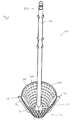
- FIG. 1 shows a foaming device 101 according to the invention.
- the foaming device 101 has a casing 102 and a foaming tool 103 with an axis 121.
- the foaming tool 103 is attached to the casing 102 in a coupling area 104.
- the foaming tool is driven by a drive unit 105 comprising an electric motor 106 and a gear system 107. Through the gear system 107 the axis 121 of the foaming tool 103 is rotated by the electric motor 106 when the electric motor 106 is engaged.
- the foaming tool 103 comprises two foaming bodies 108 and 109. In this embodiment the two foaming bodies 108 and 109 are of equal form.
- the foaming bodies 108 and 109 have the shape of hollow solids of revolution; more precisely they are of frusto-conical shape.
- the first foaming body 108 has a first substantially open side 123 and a second substantially open side 124.
- the first substantially open side 123 of the first foaming body 108 is located further from the casing 102 of the foaming device than the second substantially open side 124 of the first foaming body 108.
- the first and second substantially open sides 125 and 126 respectively of the second foaming body 109 are arranged likewise.
- the foaming bodies 108 and 109 are connected to the axis 121 of the foaming tool 103 by foaming body connecting means 110 and 111.
- foaming wings 112, 113, 114 and 115 are present within the foaming bodies 108 and 109.
- the wings might be located on the outside of the foaming body.
- a combination of wings on the inside and the outside of the foaming body is also possible.
- the foaming bodies 108 and 109 have a hollow solid 118 and 119 respectively, which is spread with a plurality of holes 120.
- the electric motor 106 is controllable by the user though a control button 116.
- the control function of the control button 116 is limited to 'on' and 'off' only. Placing the control button 116 in the 'on' position causes the electric motor 106 to rotate at a speed suited for the foaming tool 103 to create foam. Good foaming results are obtained when the foaming tool 103 rotates at a rotational speed between 800 and 1200 rounds per minute (rpm). Very good foaming results are obtained when the foaming tool rotates at a rotational speed between 900 and 1000 rpm.
- control button 116 can have various positions, such as 'off', 'low speed', 'medium speed' and 'high speed', allowing the user to control the speed at which the electric motor 106 and therefore the foaming tool 103 will rotate. This allows the user to adapt the rotational speed of the foaming tool 103 to the specific characteristics of the liquid substance to be foamed.
- the foaming device 101 has a power cord outlet 117 by which the foaming device can be connected to an electricity source, e.g. the mains.
- an electricity source e.g. the mains.
- the foaming device 101 might be cordless, having a battery or the like inside the casing 102 to provide power to the electric motor 106.
- a liquid substance When a liquid substance is to be foamed, it will usually be inside a beaker, bowl, container, or the like. While the electric motor 106 is disengaged the foaming tool 103 is positioned in the beaker, bowl, container or the like such that at least part of at least one foaming body is inside the liquid substance. In order to obtain good performance for the foaming tool 103 of Figure 1 , at least part of both foaming bodies 108 and 109 are to be submerged in the liquid substance. Following the placement of the foaming tool 103 in the liquid substance, the electric motor 106 is engaged through the control button 116. Alternatively, the electric motor might be engaged before the foaming tool 103 is placed in the liquid substance. However, this might lead to splashing the liquid substance which in general is considered to be undesirable.
- the rotation of the foaming bodies 108 and 109 insofar they are submerged in the liquid substance, will cause the liquid substance, such as milk, egg white or cream, to rotate.
- the rotation of the liquid substance is enhanced by the wings 112, 113, 114 and 115. Due to the rotation of the liquid substance centrifugal forces come into existence, forcing the liquid substance outwards, as seen in a radial direction starting from axis 121, through the holes 120 in the hollow solid 118 and 119 of the foaming bodies 108 and 109 respectively.
- the movements of the liquid substance will cause a turbulent flow pattern inside the beaker, bowl, container or the like.
- the liquid substance Due to this turbulent flow pattern gas from the surrounding atmosphere will be captured by the liquid substance. Usually, this gas will be air. To prevent spoilage of the liquid substance, it is preferable to align the axis 121 substantially vertical, or parallel to the sidewall of the beaker, bowl, container or the like.
- This liquid substance and gas is in turn forced to flow through the holes 120 of the hollow solids 118 and 119 of the foaming bodies 108 and 109 respectively.
- foam is generated.
- the user When the user is satisfied with the foaming result the user disengages the electric motor 106 and removes the foaming tool 103 from the beaker, bowl, container or the like containing the foam. Alternatively, the user might remove the foaming tool 103 while the electric motor is engaged, however this can lead to splashing the foam which is generally considered to be undesirable. It is noted that the verb "to engage”, as used in this paper, also means “to energize”.
- the foaming bodies 108 and 109 can be made of any hard materials, especially metals (e.g. aluminum, copper, stainless steel, or the like), or hard plastics. Due to the torsional forces acting on the axis 121 of the foaming tool 103, the foaming tool axis 121 is preferably made of material capable of resisting these forces like metals (e.g. aluminum, copper, stainless steel, or the like). To improve the cleanability of the foaming tool, the foaming tool can be coated with a smooth material, for example polytetrafluoroethylene (PTFE), a nano-coating or a sol-gel material.
- PTFE polytetrafluoroethylene
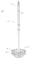
- Figure 2 shows the lower part 122 of the foaming tool 103 as shown in Figure 1 from a side perspective.
- the distance between the second substantially open sides 124 and 126 of the first and second foaming bodies 108 and 109, respectively, is denoted by d 3 .
- d 3 also denotes the distance between the first substantially open sides 123 and 125 of the first and second foaming bodies 108 and 109, respectively. Good foaming results are obtained when the distance d 3 is between substantially 25% of d 1 and substantially 175% of d 1 . Preferably, the distance d 3 is between substantially 75% of d 1 and substantially 125% of d 1 . Most preferably, the distance d 3 is substantially equal to d 1 .
- first foaming body 108 and the second foaming body 109 are arranged nested along the central axis, as the first substantially open side 123 of the first foaming body 108 is located between the first substantially open side 125 of the second foaming body 109 and the second substantially open side 126 of the second foaming body 109, seen in a direction along the axis 121.
- FIG 3 shows a detachable foaming tool 201 being detached from a foaming device (not shown).
- the foaming tool 201 has one foaming body 202 and an axis 203. During operation the foaming tool 201 is connected to a foaming device at a proximal end 210 of the axis 203 and rotated around the axis 203.
- the detachable foaming tool 201 is preferably attached to a foaming device before the foaming device is engaged.
- the coupling between the detachable foaming tool 201 and the foaming device is well known from the art and not detailedly disclosed here.
- the foaming body 202 is connected to the axis 203 by a connecting means 204.
- connection means can for example be formed by two small bars advantageously placed diametrically to each other on the axis of the foaming body connecting the foaming body with the axis.
- the person skilled in the art will recognize many other ways of connecting the foaming body to the central axis without considerably blocking either of the substantially open sides of the foaming body.
- wings 205 and 206 are present inside the one foaming body.
- the hollow solid of the foaming body 202 is spread with a plurality of holes 207.
- the foaming body 202 has a first substantially open side 208 and a second substantially open side 209.
- the first substantially open side 208 is located closest to a distal end 211 of the axis 203; the second substantially open side 209 is located closest to the proximal end 210 of the axis 203.
- FIG 4 shows a detachable foaming tool 301 being detached from a foaming device.
- the foaming tool has an axis 302.
- the foaming tool axis 302 is attached to the foaming device at a proximal end 303.
- a foaming body 305 is connected by a connecting means 306.
- the foaming body has a hollow solid 307.
- the hollow solid 307 of the foaming body 305 is spread with a plurality of holes 308.
- wings 309 and 310 are attached to the foaming body 305.
- the wings 309 and 310 enhance the motion of the foaming liquid during operation of the foaming tool.
- the embodiment of Figure 3 has two wings 309 and 310 placed substantially diametrically on the hollow solid 307 of the foaming body 305 with respect to the axis 302. In alternative embodiments a different number of wings is possible. From a constructional point of view it is preferable to have the wings distributed evenly over the circumference of the foaming body. During operation of the foaming tool, friction forces are experienced by the wings. It is advantageous to spread those friction forces evenly over the circumference of the foaming body and thereby evenly over the connecting means connecting the foaming body to the axis. Further, this enhances the rotational stability of the foaming tool.
- Wings 309 and 310 are extending substantially radially from the hollow solid 307 of the foaming body 305, whereby the sides of the sides of wings 309 and 310 make an angle ⁇ of substantially 90 degrees with the hollow solid 307 of the foaming body 305. In Figure 4 this is illustrated by a surface 311 of wing 309 making an angle ⁇ with the hollow solid 307 of the foaming body 305. In alternative embodiments the angle ⁇ can have other values.
- Figure 5 shows a detachable foaming tool 401 having an axis 402 which is attachable to a foaming device at its proximal end 403.
- Two foaming bodies 405 and 406 are provided near a distal end 404 of the axis 402.
- the foaming bodies 405 and 406 are of substantially equal form.
- the foaming body 405 has an elliptical frustum form.
Landscapes
- Chemical & Material Sciences (AREA)
- Chemical Kinetics & Catalysis (AREA)
- Engineering & Computer Science (AREA)
- Mechanical Engineering (AREA)
- Food Science & Technology (AREA)
- Food-Manufacturing Devices (AREA)
Priority Applications (1)
| Application Number | Priority Date | Filing Date | Title |
|---|---|---|---|
| EP08162361A EP2153885A1 (fr) | 2008-08-14 | 2008-08-14 | Dispositif moussant pour faire mousser une substance liquide |
Applications Claiming Priority (1)
| Application Number | Priority Date | Filing Date | Title |
|---|---|---|---|
| EP08162361A EP2153885A1 (fr) | 2008-08-14 | 2008-08-14 | Dispositif moussant pour faire mousser une substance liquide |
Publications (1)
| Publication Number | Publication Date |
|---|---|
| EP2153885A1 true EP2153885A1 (fr) | 2010-02-17 |
Family
ID=40220052
Family Applications (1)
| Application Number | Title | Priority Date | Filing Date |
|---|---|---|---|
| EP08162361A Ceased EP2153885A1 (fr) | 2008-08-14 | 2008-08-14 | Dispositif moussant pour faire mousser une substance liquide |
Country Status (1)
| Country | Link |
|---|---|
| EP (1) | EP2153885A1 (fr) |
Cited By (4)
| Publication number | Priority date | Publication date | Assignee | Title |
|---|---|---|---|---|
| EP2645906A4 (fr) * | 2010-11-29 | 2013-10-09 | Ian Geoffrey Wilson | Dispositif broyeur à main |
| JP2015047540A (ja) * | 2013-08-30 | 2015-03-16 | 株式会社石井鐵工所 | 遠心撹拌体 |
| CN118976398A (zh) * | 2024-08-05 | 2024-11-19 | 蚌埠斯维特科技有限公司 | 一种铝合金切削液制备装置及由其制备的切削液 |
| US12285730B1 (en) * | 2024-10-08 | 2025-04-29 | Shenzhen Seenda Technology Co., Ltd. | Milk frothing head and frother |
Citations (8)
| Publication number | Priority date | Publication date | Assignee | Title |
|---|---|---|---|---|
| FR809706A (fr) * | 1935-08-23 | 1937-03-09 | Distillers Co Yeast Ltd | Perfectionnements aux dispositifs d'aération des liquides ou de dispersion de gaz ou de vapeurs dans des liquides |
| DE879081C (de) * | 1951-02-23 | 1953-06-11 | Michael Philosophow | Ruehrwerk mit Luftzufuehrung |
| US4007920A (en) | 1973-08-29 | 1977-02-15 | Mark Plunguian | Mixing and aerating device |
| JPS6078630A (ja) * | 1983-10-07 | 1985-05-04 | Murata Seisakusho:Kk | 撹拌装置 |
| US5261745A (en) * | 1992-04-13 | 1993-11-16 | Watkins James R | Mixing apparatus with frusto-conically shaped impeller for mixing a liquid and a particulate solid |
| US5490727A (en) | 1992-07-16 | 1996-02-13 | Ppv-Verwaltungs-Ag | Disc-shaped mixing tool with conically beveled through bones |
| US20010022755A1 (en) * | 1999-12-20 | 2001-09-20 | Holtzapple Mark T. | Mixer system and method |
| DE20317503U1 (de) * | 2003-11-13 | 2004-02-12 | Löhken, Thomas, Dipl.-Ing. | Elektrischer Handschaumschläger |
-
2008
- 2008-08-14 EP EP08162361A patent/EP2153885A1/fr not_active Ceased
Patent Citations (8)
| Publication number | Priority date | Publication date | Assignee | Title |
|---|---|---|---|---|
| FR809706A (fr) * | 1935-08-23 | 1937-03-09 | Distillers Co Yeast Ltd | Perfectionnements aux dispositifs d'aération des liquides ou de dispersion de gaz ou de vapeurs dans des liquides |
| DE879081C (de) * | 1951-02-23 | 1953-06-11 | Michael Philosophow | Ruehrwerk mit Luftzufuehrung |
| US4007920A (en) | 1973-08-29 | 1977-02-15 | Mark Plunguian | Mixing and aerating device |
| JPS6078630A (ja) * | 1983-10-07 | 1985-05-04 | Murata Seisakusho:Kk | 撹拌装置 |
| US5261745A (en) * | 1992-04-13 | 1993-11-16 | Watkins James R | Mixing apparatus with frusto-conically shaped impeller for mixing a liquid and a particulate solid |
| US5490727A (en) | 1992-07-16 | 1996-02-13 | Ppv-Verwaltungs-Ag | Disc-shaped mixing tool with conically beveled through bones |
| US20010022755A1 (en) * | 1999-12-20 | 2001-09-20 | Holtzapple Mark T. | Mixer system and method |
| DE20317503U1 (de) * | 2003-11-13 | 2004-02-12 | Löhken, Thomas, Dipl.-Ing. | Elektrischer Handschaumschläger |
Cited By (5)
| Publication number | Priority date | Publication date | Assignee | Title |
|---|---|---|---|---|
| EP2645906A4 (fr) * | 2010-11-29 | 2013-10-09 | Ian Geoffrey Wilson | Dispositif broyeur à main |
| US8672250B2 (en) | 2010-11-29 | 2014-03-18 | Ian Geoffrey Wilson | Hand held masher device |
| JP2015047540A (ja) * | 2013-08-30 | 2015-03-16 | 株式会社石井鐵工所 | 遠心撹拌体 |
| CN118976398A (zh) * | 2024-08-05 | 2024-11-19 | 蚌埠斯维特科技有限公司 | 一种铝合金切削液制备装置及由其制备的切削液 |
| US12285730B1 (en) * | 2024-10-08 | 2025-04-29 | Shenzhen Seenda Technology Co., Ltd. | Milk frothing head and frother |
Similar Documents
| Publication | Publication Date | Title |
|---|---|---|
| JP4418019B1 (ja) | 攪拌用回転体および攪拌装置 | |
| EP2386350A1 (fr) | Corps d'agitation rotatif et dispositif d'agitation | |
| US20020034121A1 (en) | Bell-shaped shield for use on a household appliance, particularly a hand blender or a hand mixer | |
| EP2153885A1 (fr) | Dispositif moussant pour faire mousser une substance liquide | |
| CN104853659B (zh) | 食品搅拌装置 | |
| US3942770A (en) | Device for stirring a liquid | |
| JP5754994B2 (ja) | 攪拌装置 | |
| US20130135962A1 (en) | Stirring Apparatus | |
| JPH10337461A (ja) | 攪拌装置 | |
| JP2010240172A (ja) | 泡立て器 | |
| RU2662389C2 (ru) | Инструмент для кухонного прибора с облицовочным покрытием | |
| JP5597315B1 (ja) | 攪拌装置 | |
| CA2919280A1 (fr) | Ejecteur de bulle de gaz rotatif | |
| KR101949947B1 (ko) | 기체 유도관 및 이를 이용한 임펠러 | |
| JP3179575U (ja) | 攪拌機 | |
| JP5302265B2 (ja) | 攪拌用回転体および攪拌装置 | |
| CA2506286A1 (fr) | Agitateur, dispositif de nettoyage circulatoire fixe a l'agitateur, et systeme annulaire comprenant ce dispositif | |
| CN201012319Y (zh) | 一种油墨快速分散装置 | |
| JP2017176980A (ja) | 撹拌翼及び撹拌装置 | |
| JP6074647B2 (ja) | 攪拌方法および攪拌装置 | |
| JP2008284492A (ja) | 撹拌装置 | |
| JP5385480B2 (ja) | 攪拌用回転体および攪拌装置 | |
| JP3160718U (ja) | 循環式上下軸流撹拌装置 | |
| CN104379246B (zh) | 双锥式泵送装置 | |
| JP2006043668A (ja) | 流体撹拌装置、それに用いるタービン型撹拌機及び邪魔板 |
Legal Events
| Date | Code | Title | Description |
|---|---|---|---|
| PUAI | Public reference made under article 153(3) epc to a published international application that has entered the european phase |
Free format text: ORIGINAL CODE: 0009012 |
|
| AK | Designated contracting states |
Kind code of ref document: A1 Designated state(s): AT BE BG CH CY CZ DE DK EE ES FI FR GB GR HR HU IE IS IT LI LT LU LV MC MT NL NO PL PT RO SE SI SK TR |
|
| AX | Request for extension of the european patent |
Extension state: AL BA MK RS |
|
| STAA | Information on the status of an ep patent application or granted ep patent |
Free format text: STATUS: THE APPLICATION HAS BEEN REFUSED |
|
| 18R | Application refused |
Effective date: 20100318 |