EP2153995A1 - Unterdrückung von Artefakten beim Tintenstrahldrucken - Google Patents
Unterdrückung von Artefakten beim Tintenstrahldrucken Download PDFInfo
- Publication number
- EP2153995A1 EP2153995A1 EP09176828A EP09176828A EP2153995A1 EP 2153995 A1 EP2153995 A1 EP 2153995A1 EP 09176828 A EP09176828 A EP 09176828A EP 09176828 A EP09176828 A EP 09176828A EP 2153995 A1 EP2153995 A1 EP 2153995A1
- Authority
- EP
- European Patent Office
- Prior art keywords
- label
- drop
- printed
- printing
- blocks
- Prior art date
- Legal status (The legal status is an assumption and is not a legal conclusion. Google has not performed a legal analysis and makes no representation as to the accuracy of the status listed.)
- Withdrawn
Links
- 238000007641 inkjet printing Methods 0.000 title description 15
- 230000001629 suppression Effects 0.000 title description 2
- 238000007639 printing Methods 0.000 claims abstract description 131
- 238000000034 method Methods 0.000 claims abstract description 96
- 239000012530 fluid Substances 0.000 claims description 14
- 238000010586 diagram Methods 0.000 description 23
- 230000015572 biosynthetic process Effects 0.000 description 18
- 238000012545 processing Methods 0.000 description 15
- 238000004422 calculation algorithm Methods 0.000 description 14
- 238000012937 correction Methods 0.000 description 14
- 238000005516 engineering process Methods 0.000 description 10
- 238000003384 imaging method Methods 0.000 description 9
- 230000033001 locomotion Effects 0.000 description 9
- 230000000694 effects Effects 0.000 description 8
- 230000006872 improvement Effects 0.000 description 8
- 230000004075 alteration Effects 0.000 description 7
- 230000008859 change Effects 0.000 description 7
- 230000003247 decreasing effect Effects 0.000 description 7
- 238000004519 manufacturing process Methods 0.000 description 7
- 230000008901 benefit Effects 0.000 description 6
- 230000007547 defect Effects 0.000 description 6
- 230000001419 dependent effect Effects 0.000 description 5
- 238000001208 nuclear magnetic resonance pulse sequence Methods 0.000 description 5
- 238000009792 diffusion process Methods 0.000 description 4
- 230000007246 mechanism Effects 0.000 description 4
- 230000006870 function Effects 0.000 description 3
- 230000003252 repetitive effect Effects 0.000 description 3
- 230000004913 activation Effects 0.000 description 2
- 238000013459 approach Methods 0.000 description 2
- 230000009286 beneficial effect Effects 0.000 description 2
- 238000013461 design Methods 0.000 description 2
- 239000006185 dispersion Substances 0.000 description 2
- 238000006073 displacement reaction Methods 0.000 description 2
- 239000007788 liquid Substances 0.000 description 2
- 238000012986 modification Methods 0.000 description 2
- 230000004048 modification Effects 0.000 description 2
- 230000003287 optical effect Effects 0.000 description 2
- 230000000737 periodic effect Effects 0.000 description 2
- 230000008569 process Effects 0.000 description 2
- 238000009877 rendering Methods 0.000 description 2
- 230000004044 response Effects 0.000 description 2
- 239000007787 solid Substances 0.000 description 2
- 239000000758 substrate Substances 0.000 description 2
- 235000014443 Pyrus communis Nutrition 0.000 description 1
- 230000002730 additional effect Effects 0.000 description 1
- 238000004364 calculation method Methods 0.000 description 1
- 238000012512 characterization method Methods 0.000 description 1
- 238000013144 data compression Methods 0.000 description 1
- 230000003111 delayed effect Effects 0.000 description 1
- 238000007786 electrostatic charging Methods 0.000 description 1
- 230000007613 environmental effect Effects 0.000 description 1
- 239000000835 fiber Substances 0.000 description 1
- 238000010348 incorporation Methods 0.000 description 1
- 235000020130 leben Nutrition 0.000 description 1
- 230000000873 masking effect Effects 0.000 description 1
- 239000011159 matrix material Substances 0.000 description 1
- 238000005259 measurement Methods 0.000 description 1
- 230000009467 reduction Effects 0.000 description 1
- 230000000979 retarding effect Effects 0.000 description 1
- 238000005070 sampling Methods 0.000 description 1
- 238000012216 screening Methods 0.000 description 1
- 238000007493 shaping process Methods 0.000 description 1
- 230000008054 signal transmission Effects 0.000 description 1
- 239000013589 supplement Substances 0.000 description 1
- 238000012546 transfer Methods 0.000 description 1
- 230000007723 transport mechanism Effects 0.000 description 1
- 230000000007 visual effect Effects 0.000 description 1
Images


Classifications
-
- B—PERFORMING OPERATIONS; TRANSPORTING
- B41—PRINTING; LINING MACHINES; TYPEWRITERS; STAMPS
- B41J—TYPEWRITERS; SELECTIVE PRINTING MECHANISMS, i.e. MECHANISMS PRINTING OTHERWISE THAN FROM A FORME; CORRECTION OF TYPOGRAPHICAL ERRORS
- B41J2/00—Typewriters or selective printing mechanisms characterised by the printing or marking process for which they are designed
- B41J2/005—Typewriters or selective printing mechanisms characterised by the printing or marking process for which they are designed characterised by bringing liquid or particles selectively into contact with a printing material
- B41J2/01—Ink jet
- B41J2/015—Ink jet characterised by the jet generation process
- B41J2/02—Ink jet characterised by the jet generation process generating a continuous ink jet
- B41J2/03—Ink jet characterised by the jet generation process generating a continuous ink jet by pressure
-
- B—PERFORMING OPERATIONS; TRANSPORTING
- B41—PRINTING; LINING MACHINES; TYPEWRITERS; STAMPS
- B41J—TYPEWRITERS; SELECTIVE PRINTING MECHANISMS, i.e. MECHANISMS PRINTING OTHERWISE THAN FROM A FORME; CORRECTION OF TYPOGRAPHICAL ERRORS
- B41J2/00—Typewriters or selective printing mechanisms characterised by the printing or marking process for which they are designed
- B41J2/005—Typewriters or selective printing mechanisms characterised by the printing or marking process for which they are designed characterised by bringing liquid or particles selectively into contact with a printing material
- B41J2/01—Ink jet
- B41J2/015—Ink jet characterised by the jet generation process
- B41J2/02—Ink jet characterised by the jet generation process generating a continuous ink jet
- B41J2002/022—Control methods or devices for continuous ink jet
-
- B—PERFORMING OPERATIONS; TRANSPORTING
- B41—PRINTING; LINING MACHINES; TYPEWRITERS; STAMPS
- B41J—TYPEWRITERS; SELECTIVE PRINTING MECHANISMS, i.e. MECHANISMS PRINTING OTHERWISE THAN FROM A FORME; CORRECTION OF TYPOGRAPHICAL ERRORS
- B41J2/00—Typewriters or selective printing mechanisms characterised by the printing or marking process for which they are designed
- B41J2/005—Typewriters or selective printing mechanisms characterised by the printing or marking process for which they are designed characterised by bringing liquid or particles selectively into contact with a printing material
- B41J2/01—Ink jet
- B41J2/015—Ink jet characterised by the jet generation process
- B41J2/02—Ink jet characterised by the jet generation process generating a continuous ink jet
- B41J2/03—Ink jet characterised by the jet generation process generating a continuous ink jet by pressure
- B41J2002/031—Gas flow deflection
-
- B—PERFORMING OPERATIONS; TRANSPORTING
- B41—PRINTING; LINING MACHINES; TYPEWRITERS; STAMPS
- B41J—TYPEWRITERS; SELECTIVE PRINTING MECHANISMS, i.e. MECHANISMS PRINTING OTHERWISE THAN FROM A FORME; CORRECTION OF TYPOGRAPHICAL ERRORS
- B41J2/00—Typewriters or selective printing mechanisms characterised by the printing or marking process for which they are designed
- B41J2/005—Typewriters or selective printing mechanisms characterised by the printing or marking process for which they are designed characterised by bringing liquid or particles selectively into contact with a printing material
- B41J2/01—Ink jet
- B41J2/015—Ink jet characterised by the jet generation process
- B41J2/02—Ink jet characterised by the jet generation process generating a continuous ink jet
- B41J2/03—Ink jet characterised by the jet generation process generating a continuous ink jet by pressure
- B41J2002/033—Continuous stream with droplets of different sizes
Definitions
- the first technology provides ink droplets which impact upon a recording surface by using a pressurization actuator (thermal, piezoelectric, etc.). Selective activation of the actuator causes the formation and ejection of a flying ink droplet that crosses the space between the print head and the print media and strikes the print media.
- the formation of printed images is achieved by controlling the individual formation of ink droplets, as is required to create the desired image.
- Commonly practiced drop-on-demand technologies use thermal actuation to eject ink droplets from a nozzle.
- the second technology uses a pressurized ink source that produces a continuous stream of ink droplets.
- Conventional continuous ink jet printers utilize electrostatic charging devices that are placed close to the point where a filament of ink breaks into individual ink droplets.
- the ink droplets are electrically charged and then directed to an appropriate location by deflection electrodes.
- the ink droplets are directed into an ink-capturing mechanism (often referred to as catcher, interceptor, or gutter).
- catcher, interceptor, or gutter When a print is desired, the ink droplets are directed to strike a print medium.
- 6,450,628 discloses a print head that allows multiple printing drop sizes for multi-level printing. Drops are formed by at least one electrical pulse within an interval P, but there are no heater activation electrical pulses located between any two intervals P. Instead, at least one electrical pulse 65 is included in each interval P.
- control of drop placement can be used to directly compensate nozzle manufacturing defects which result in drop placement errors, for example by using a lookup table in which manufacturing defects were quantified; in other cases, control of drop placement can be used to directly improve image quality even in the absence of drop placement errors.
- improvements in image quality can be achieved by deliberately altering the positions of drops within printed pixel areas in an imagewise fashion when printing text. Such alterations can better replicate the intended positions of sharply defined image features such as curved portions of script fonts. Control of drop placement is useful in producing halftone images for graphic arts proofing.
- drop-on-demand inkjet printers in particular use multiple passes (so-called banding passes) in printing images, each banding pass using a different subset of nozzles on the printhead to eject drops.
- Nozzles are selected dependent on particular algorithms or are selected at random. Repetitive errors in drop placement can thereby be distributed spatially. For example, drops printed in two adjacent lines parallel to the scanning direction of the printhead (fast scan direction) would be printed by many nozzles, each subject to its own slight misdirection and consequent drop misplacement, so as to reduce repetitive misplacements. This technique introduces pseudo random spatial variations in drop position.
- Such positional "noise” in the printed drop while itself an image artifact, is generally agreed to be preferred to the case of repetitive misdirection, which is more easily detected by the eye.
- the use of banding passes is effective even in cases in which misplacements of printed drops change unpredictably with time and/or do not arise from nozzle imperfections. For example, distortion of the media due to wet loading, can result in image artifacts due to misplacement of drops one to another and environmental factors such as mechanical vibrations in the printer or fluctuating air currents near the printhead can also result in image artifacts due to misplacement of drops.
- multiple banding passes enable a printhead to correct for known banding errors, a more complex printing pattern is required as well as a more complex medium transport mechanism.
- banding passes necessarily requires more time to print an image, since not all nozzles are used all the time. Under worst-case conditions, correction for band effects can result in significant loss of productivity, even as high as 10X by some estimates. It should be noted that most continuous inkjet printers do not have scanned printheads and hence cannot easily adapt approaches such as the use of banding passes common in drop-on-demand printers.
- the present invention provides a subdivided interval for droplet formation, allowing a number of flexible timing arrangements for droplet delivery from each individual inkjet nozzle and enabling a compact means of representing and controlling such timing arrangements.
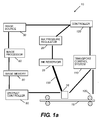
- Droplet controller 90 provides the drive signals for ejecting individual ink droplets from print head 16 to recording medium 18 according to the image data obtained from image memory 80.
- Image data may include raw image data, additional image data generated from image processing algorithms to improve the quality of printed images, and data for drop placement corrections, which can be generated from many sources, for example, from measurements of the steering errors of each nozzle 21 in printhead 16, as is well known to one skilled in the art of printhead characterization and image processing.
- Image memory 80 can therefore be viewed as a general source of data for drop ejection, such as the desired volume of ink drops to be printed, the exact location of printed drops, and shape of printed drops, as will we described.
- Ink pressure regulator 26 if present, regulates pressure in an ink reservoir 28 that is connected to print head 16 by means of a conduit 150.
- a conduit 150 For example, in the case of page-width print heads, it is convenient to move recording medium 18 past a stationary print head 16. On the other hand, in the case of scanning-type printing systems, it is more convenient to move print head 16 along one axis (i.e., a sub-scanning direction usually referred to as the fast scan direction) and recording medium 18 along an orthogonal axis (i.e., a main scanning direction usually referred to as the slow scan direction), in relative raster motion.
- a sub-scanning direction usually referred to as the fast scan direction
- an orthogonal axis i.e., a main scanning direction usually referred to as the slow scan direction
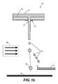
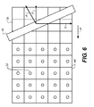
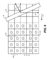
- Fig. 2 there is shown a plane view of a small number of printed drops 32 printed by print head 16 within pixel areas 44 on recording medium 18.
- each printed drop 32 is centered within its corresponding pixel area 44.
- not all printed drops 32 in any sampling meet this ideal condition, due to manufacturing imperfections, for example.
- printed drop 32 positioning with respect to fast scan direction F of print head 16, slow scan direction S, and the directions of a deflecting air flow A US Patent Application Publication No. 2003/0202054 ).
- printhead 16 provides a continuous stream of ink droplets.
- the continuous flow ink jet printer directs printing droplets to the surface of recording medium 18 and deflects non-printing droplets to a catcher, gutter, or similar device using the deflecting air flow which flows in the direction A.
- the apparatus and method of the present invention uses the same basic droplet formation and deflection methods of these earlier patents, and also provides improved droplet timing techniques and improved techniques for quantifying image data in order to position and shape droplets with in pixel areas on a recording medium.
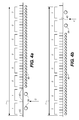
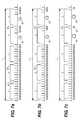
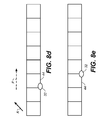
- Fig. 3a there is shown a timing diagram corresponding to a time interval I which has been divided into a plurality of subintervals 34, shown of equal duration in Fig. 3a and in the enlargement of Fig. 3a included for clarity.
- drop forming pulses 42 (or pulses 42) can be provided between adjacent subintervals 34.
- Such drop forming pulses are represented schematically in Fig. 3b , which illustrates the case of drop forming pulses 42 placed between all adjacent subintervals.
- Certain patterns of drop forming pulses can cause printing drops to form at particular nozzles on printhead 16 of Fig.
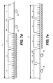
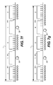
- the grouping of subintervals 34 into blocks 36 is employed in the present invention to efficiently use image data to produce desired drop forming pulse arrangements in interval I which can cause one or more printing droplets 38 to be placed within a corresponding pixel area 44, corresponding, for example, to the a pixel of information, a plurality of which generally comprise digital images.
- the drop forming pulses 42 are present between all subintervals in all blocks and drop forming pulses 43 are present between all blocks.
- printhead 16 in response to drop forming pulses, typically voltage pulses carried by connecting wires, produces a continuous series of non-printing droplets, as described in the above-referenced '821 Chwalek et al. and '197 Hawkins et al. patents describing the formation of droplets at print head.
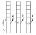
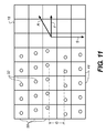
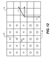
- centroid C of the traveling printing drops can be said to be the spatial location midway between the printing droplets 38 as they travel through the air; or, in general, as the location at which the density of ink weighted by its distance from the centroid is equal along both directions of the droplet trajectories.
- Other related definitions of a centroid are possible, as can be appreciated by one skilled in the art of inkjet printing; but in general the concept of a centroid is useful in discussing the dependence of the location of drops printed on a recording medium on the sequence of drop forming pulses.
- the elongation of printed drops 38 printed onto recording medium 18 can be changed so that not only the centroid of the printed drop can be caused to lie at any location within its associated pixel area but so that the printed drop may be elongated in the fast scan direction.
Landscapes
- Ink Jet (AREA)
- Particle Formation And Scattering Control In Inkjet Printers (AREA)
Applications Claiming Priority (2)
| Application Number | Priority Date | Filing Date | Title |
|---|---|---|---|
| US10/903,051 US7273269B2 (en) | 2004-07-30 | 2004-07-30 | Suppression of artifacts in inkjet printing |
| EP05776458A EP1778491A1 (de) | 2004-07-30 | 2005-07-27 | Unterdrückung von artefakten beim tintenstrahldrucken |
Related Parent Applications (1)
| Application Number | Title | Priority Date | Filing Date |
|---|---|---|---|
| EP05776458.1 Division | 2005-07-27 |
Publications (1)
| Publication Number | Publication Date |
|---|---|
| EP2153995A1 true EP2153995A1 (de) | 2010-02-17 |
Family
ID=35276974
Family Applications (2)
| Application Number | Title | Priority Date | Filing Date |
|---|---|---|---|
| EP09176828A Withdrawn EP2153995A1 (de) | 2004-07-30 | 2005-07-27 | Unterdrückung von Artefakten beim Tintenstrahldrucken |
| EP05776458A Withdrawn EP1778491A1 (de) | 2004-07-30 | 2005-07-27 | Unterdrückung von artefakten beim tintenstrahldrucken |
Family Applications After (1)
| Application Number | Title | Priority Date | Filing Date |
|---|---|---|---|
| EP05776458A Withdrawn EP1778491A1 (de) | 2004-07-30 | 2005-07-27 | Unterdrückung von artefakten beim tintenstrahldrucken |
Country Status (3)
| Country | Link |
|---|---|
| US (1) | US7273269B2 (de) |
| EP (2) | EP2153995A1 (de) |
| WO (1) | WO2006014998A1 (de) |
Families Citing this family (6)
| Publication number | Priority date | Publication date | Assignee | Title |
|---|---|---|---|---|
| US7261396B2 (en) * | 2004-10-14 | 2007-08-28 | Eastman Kodak Company | Continuous inkjet printer having adjustable drop placement |
| FR2952851B1 (fr) * | 2009-11-23 | 2012-02-24 | Markem Imaje | Imprimante a jet d'encre continu a qualite et autonomie d'impression ameliorees |
| JP5382008B2 (ja) | 2011-01-21 | 2014-01-08 | ブラザー工業株式会社 | 画像処理装置及び画像処理プログラム |
| JP5382009B2 (ja) * | 2011-01-21 | 2014-01-08 | ブラザー工業株式会社 | 画像処理装置及び画像処理プログラム |
| US8469495B2 (en) * | 2011-07-14 | 2013-06-25 | Eastman Kodak Company | Producing ink drops in a printing apparatus |
| JP6313148B2 (ja) * | 2014-07-11 | 2018-04-18 | 東レエンジニアリング株式会社 | マーキング装置 |
Citations (22)
| Publication number | Priority date | Publication date | Assignee | Title |
|---|---|---|---|---|
| US1941001A (en) | 1929-01-19 | 1933-12-26 | Rca Corp | Recorder |
| US3373437A (en) | 1964-03-25 | 1968-03-12 | Richard G. Sweet | Fluid droplet recorder with a plurality of jets |
| US4347521A (en) | 1980-11-03 | 1982-08-31 | Xerox Corporation | Tilted deflection electrode method and apparatus for liquid drop printing systems |
| US4384296A (en) | 1981-04-24 | 1983-05-17 | Xerox Corporation | Linear ink jet deflection method and apparatus |
| US4613871A (en) | 1985-11-12 | 1986-09-23 | Eastman Kodak Company | Guard drops in an ink jet printer |
| US4620196A (en) | 1985-01-31 | 1986-10-28 | Carl H. Hertz | Method and apparatus for high resolution ink jet printing |
| US4636808A (en) | 1985-09-09 | 1987-01-13 | Eastman Kodak Company | Continuous ink jet printer |
| US5224843A (en) | 1989-06-14 | 1993-07-06 | Westonbridge International Ltd. | Two valve micropump with improved outlet |
| US5726772A (en) | 1990-12-04 | 1998-03-10 | Research Corporation Technologies | Method and apparatus for halftone rendering of a gray scale image using a blue noise mask |
| US5875287A (en) | 1996-02-26 | 1999-02-23 | Seiko Epson Corporation | Banding noise reduction for clustered-dot dither |
| US5937145A (en) | 1997-06-09 | 1999-08-10 | Hewlett-Packard Company | Method and apparatus for improving ink-jet print quality using a jittered print mode |
| US6079821A (en) | 1997-10-17 | 2000-06-27 | Eastman Kodak Company | Continuous ink jet printer with asymmetric heating drop deflection |
| US6189991B1 (en) * | 1998-08-14 | 2001-02-20 | Eastman Kodak Company | Compensating for receiver skew and changing resolution in ink jet printer |
| US6367909B1 (en) | 1999-11-23 | 2002-04-09 | Xerox Corporation | Method and apparatus for reducing drop placement error in printers |
| US6443549B1 (en) | 2000-02-04 | 2002-09-03 | Scitex Digital Printing, Inc. | Continuous tone reproduction using improved ink jet droplet dispersion techniques |
| US6450628B1 (en) | 2001-06-27 | 2002-09-17 | Eastman Kodak Company | Continuous ink jet printing apparatus with nozzles having different diameters |
| US6460972B1 (en) | 2001-11-06 | 2002-10-08 | Eastman Kodak Company | Thermal actuator drop-on-demand apparatus and method for high frequency |
| US6474784B1 (en) | 1998-12-08 | 2002-11-05 | Seiko Epson Corporation | Ink-jet head, ink jet printer, and its driving method |
| US6491362B1 (en) | 2001-07-20 | 2002-12-10 | Eastman Kodak Company | Continuous ink jet printing apparatus with improved drop placement |
| US6517197B2 (en) | 2001-03-13 | 2003-02-11 | Eastman Kodak Company | Continuous ink-jet printing method and apparatus for correcting ink drop replacement |
| US6588888B2 (en) | 2000-12-28 | 2003-07-08 | Eastman Kodak Company | Continuous ink-jet printing method and apparatus |
| WO2006044008A1 (en) | 2004-10-14 | 2006-04-27 | Eastman Kodak Company | Method of adjusting drop placement in a continuous inkjet printer |
Family Cites Families (9)
| Publication number | Priority date | Publication date | Assignee | Title |
|---|---|---|---|---|
| US6513906B1 (en) * | 1991-06-06 | 2003-02-04 | Canon Kabushiki Kaisha | Recording apparatus and recording method |
| JP3339724B2 (ja) * | 1992-09-29 | 2002-10-28 | 株式会社リコー | インクジェット記録方法及びその装置 |
| JP4617571B2 (ja) * | 2000-12-19 | 2011-01-26 | リコープリンティングシステムズ株式会社 | マルチノズルインクジェット記録装置 |
| US6505921B2 (en) * | 2000-12-28 | 2003-01-14 | Eastman Kodak Company | Ink jet apparatus having amplified asymmetric heating drop deflection |
| US6554410B2 (en) * | 2000-12-28 | 2003-04-29 | Eastman Kodak Company | Printhead having gas flow ink droplet separation and method of diverging ink droplets |
| US6478414B2 (en) * | 2000-12-28 | 2002-11-12 | Eastman Kodak Company | Drop-masking continuous inkjet printing method and apparatus |
| US6712441B2 (en) * | 2001-02-16 | 2004-03-30 | Seiko Epson Corporation | Printing apparatus and method implementing smooth outline |
| US6851796B2 (en) * | 2001-10-31 | 2005-02-08 | Eastman Kodak Company | Continuous ink-jet printing apparatus having an improved droplet deflector and catcher |
| US6746108B1 (en) * | 2002-11-18 | 2004-06-08 | Eastman Kodak Company | Method and apparatus for printing ink droplets that strike print media substantially perpendicularly |
-
2004
- 2004-07-30 US US10/903,051 patent/US7273269B2/en not_active Expired - Fee Related
-
2005
- 2005-07-27 EP EP09176828A patent/EP2153995A1/de not_active Withdrawn
- 2005-07-27 WO PCT/US2005/026560 patent/WO2006014998A1/en not_active Ceased
- 2005-07-27 EP EP05776458A patent/EP1778491A1/de not_active Withdrawn
Patent Citations (23)
| Publication number | Priority date | Publication date | Assignee | Title |
|---|---|---|---|---|
| US1941001A (en) | 1929-01-19 | 1933-12-26 | Rca Corp | Recorder |
| US3373437A (en) | 1964-03-25 | 1968-03-12 | Richard G. Sweet | Fluid droplet recorder with a plurality of jets |
| US4347521A (en) | 1980-11-03 | 1982-08-31 | Xerox Corporation | Tilted deflection electrode method and apparatus for liquid drop printing systems |
| US4384296A (en) | 1981-04-24 | 1983-05-17 | Xerox Corporation | Linear ink jet deflection method and apparatus |
| US4620196A (en) | 1985-01-31 | 1986-10-28 | Carl H. Hertz | Method and apparatus for high resolution ink jet printing |
| US4636808A (en) | 1985-09-09 | 1987-01-13 | Eastman Kodak Company | Continuous ink jet printer |
| US4613871A (en) | 1985-11-12 | 1986-09-23 | Eastman Kodak Company | Guard drops in an ink jet printer |
| US5224843A (en) | 1989-06-14 | 1993-07-06 | Westonbridge International Ltd. | Two valve micropump with improved outlet |
| US5726772A (en) | 1990-12-04 | 1998-03-10 | Research Corporation Technologies | Method and apparatus for halftone rendering of a gray scale image using a blue noise mask |
| US5875287A (en) | 1996-02-26 | 1999-02-23 | Seiko Epson Corporation | Banding noise reduction for clustered-dot dither |
| US5937145A (en) | 1997-06-09 | 1999-08-10 | Hewlett-Packard Company | Method and apparatus for improving ink-jet print quality using a jittered print mode |
| US6079821A (en) | 1997-10-17 | 2000-06-27 | Eastman Kodak Company | Continuous ink jet printer with asymmetric heating drop deflection |
| US6189991B1 (en) * | 1998-08-14 | 2001-02-20 | Eastman Kodak Company | Compensating for receiver skew and changing resolution in ink jet printer |
| US6474784B1 (en) | 1998-12-08 | 2002-11-05 | Seiko Epson Corporation | Ink-jet head, ink jet printer, and its driving method |
| US6367909B1 (en) | 1999-11-23 | 2002-04-09 | Xerox Corporation | Method and apparatus for reducing drop placement error in printers |
| US6443549B1 (en) | 2000-02-04 | 2002-09-03 | Scitex Digital Printing, Inc. | Continuous tone reproduction using improved ink jet droplet dispersion techniques |
| US6588888B2 (en) | 2000-12-28 | 2003-07-08 | Eastman Kodak Company | Continuous ink-jet printing method and apparatus |
| US20030202054A1 (en) | 2000-12-28 | 2003-10-30 | Eastman Kodak Company | Continuous ink-jet printing method and apparatus |
| US6517197B2 (en) | 2001-03-13 | 2003-02-11 | Eastman Kodak Company | Continuous ink-jet printing method and apparatus for correcting ink drop replacement |
| US6450628B1 (en) | 2001-06-27 | 2002-09-17 | Eastman Kodak Company | Continuous ink jet printing apparatus with nozzles having different diameters |
| US6491362B1 (en) | 2001-07-20 | 2002-12-10 | Eastman Kodak Company | Continuous ink jet printing apparatus with improved drop placement |
| US6460972B1 (en) | 2001-11-06 | 2002-10-08 | Eastman Kodak Company | Thermal actuator drop-on-demand apparatus and method for high frequency |
| WO2006044008A1 (en) | 2004-10-14 | 2006-04-27 | Eastman Kodak Company | Method of adjusting drop placement in a continuous inkjet printer |
Also Published As
| Publication number | Publication date |
|---|---|
| WO2006014998A1 (en) | 2006-02-09 |
| US20060023011A1 (en) | 2006-02-02 |
| EP1778491A1 (de) | 2007-05-02 |
| US7273269B2 (en) | 2007-09-25 |
Similar Documents
| Publication | Publication Date | Title |
|---|---|---|
| US7748829B2 (en) | Adjustable drop placement printing method | |
| US7073883B2 (en) | Method of aligning inkjet nozzle banks for an inkjet printer | |
| US5258774A (en) | Compensation for aerodynamic influences in ink jet apparatuses having ink jet chambers utilizing a plurality of orifices | |
| US6457806B2 (en) | Ink-jet print pass microstepping | |
| US4091390A (en) | Arrangement for multi-orifice ink jet print head | |
| EP0914950A2 (de) | Aus Druckkopfen mit Reihen mit partieller Breite zusammengesetzter Tintenstrahldruckkopf | |
| US20040080555A1 (en) | Positional deviation correction using reference and relative correction values in bi-directional printing | |
| CN1500635A (zh) | 用于打印基本垂直触击打印介质的墨水微滴的方法和装置 | |
| US7438396B2 (en) | Inkjet printing method and apparatus | |
| US7273269B2 (en) | Suppression of artifacts in inkjet printing | |
| EP1647404B1 (de) | Drucker und Herstellungsverfahren der Kopfeinheit | |
| EP1221380B1 (de) | Bestimmung des einstellwertes für eine aufzeichnungspositionsabweichung beim drucken unter verwendung mehrerer arten von inspektionsmustern | |
| CA1097720A (en) | Ink jet nozzle arrangement | |
| EP1126977B1 (de) | Tintenstrahldrucksystem | |
| US6508537B2 (en) | Ink jet recording device capable of controlling impact positions of ink droplets in electrical manner | |
| US6527375B2 (en) | Ink jet recording device capable of controlling impact positions of ink droplets | |
| US20050146547A1 (en) | Electronic tilt adjustment in fluid-jet fluid ejecting heads | |
| US8967770B2 (en) | Inkjet printer and printing method | |
| EP1745934B1 (de) | Markierungsvorrichtung, Markierungsverfahren und Programm um die Druckqualität zu verbessern | |
| JPH06286223A (ja) | カラー画像記録装置 | |
| JPH09290532A (ja) | 副走査制御方法及び印刷装置 | |
| JP2003039684A (ja) | インクジェット記録装置 | |
| HK1064643A (en) | Method and apparatus for printing ink droplets that strike print media substantially perpendicularly |
Legal Events
| Date | Code | Title | Description |
|---|---|---|---|
| PUAI | Public reference made under article 153(3) epc to a published international application that has entered the european phase |
Free format text: ORIGINAL CODE: 0009012 |
|
| AC | Divisional application: reference to earlier application |
Ref document number: 1778491 Country of ref document: EP Kind code of ref document: P |
|
| AK | Designated contracting states |
Kind code of ref document: A1 Designated state(s): DE FR GB |
|
| STAA | Information on the status of an ep patent application or granted ep patent |
Free format text: STATUS: THE APPLICATION IS DEEMED TO BE WITHDRAWN |
|
| 18D | Application deemed to be withdrawn |
Effective date: 20100818 |