EP2154092A2 - Dispositif d'alimentation en matériau à haut rendement pour le transport pneumatique de particules solides - Google Patents
Dispositif d'alimentation en matériau à haut rendement pour le transport pneumatique de particules solides Download PDFInfo
- Publication number
- EP2154092A2 EP2154092A2 EP09167898A EP09167898A EP2154092A2 EP 2154092 A2 EP2154092 A2 EP 2154092A2 EP 09167898 A EP09167898 A EP 09167898A EP 09167898 A EP09167898 A EP 09167898A EP 2154092 A2 EP2154092 A2 EP 2154092A2
- Authority
- EP
- European Patent Office
- Prior art keywords
- particulate
- pipeline
- prime mover
- assembly
- inlet
- Prior art date
- Legal status (The legal status is an assumption and is not a legal conclusion. Google has not performed a legal analysis and makes no representation as to the accuracy of the status listed.)
- Withdrawn
Links
- 239000007787 solid Substances 0.000 title claims abstract description 32
- 239000000463 material Substances 0.000 title claims description 16
- 238000012546 transfer Methods 0.000 claims abstract description 18
- 239000012530 fluid Substances 0.000 claims description 21
- 238000004891 communication Methods 0.000 claims description 4
- 238000013459 approach Methods 0.000 description 9
- 238000012545 processing Methods 0.000 description 8
- 239000002956 ash Substances 0.000 description 5
- 238000012986 modification Methods 0.000 description 5
- 230000004048 modification Effects 0.000 description 5
- IJGRMHOSHXDMSA-UHFFFAOYSA-N Atomic nitrogen Chemical compound N#N IJGRMHOSHXDMSA-UHFFFAOYSA-N 0.000 description 4
- 230000006870 function Effects 0.000 description 4
- 238000000034 method Methods 0.000 description 4
- 230000007423 decrease Effects 0.000 description 3
- 230000006872 improvement Effects 0.000 description 3
- 230000008569 process Effects 0.000 description 3
- 238000009825 accumulation Methods 0.000 description 2
- 239000010881 fly ash Substances 0.000 description 2
- 229910052757 nitrogen Inorganic materials 0.000 description 2
- 238000003860 storage Methods 0.000 description 2
- 238000007792 addition Methods 0.000 description 1
- 239000010882 bottom ash Substances 0.000 description 1
- 238000005266 casting Methods 0.000 description 1
- 230000008859 change Effects 0.000 description 1
- 230000007613 environmental effect Effects 0.000 description 1
- 238000011065 in-situ storage Methods 0.000 description 1
- 238000009434 installation Methods 0.000 description 1
- 238000012423 maintenance Methods 0.000 description 1
- 238000004519 manufacturing process Methods 0.000 description 1
- 239000000203 mixture Substances 0.000 description 1
- 238000000465 moulding Methods 0.000 description 1
- 239000002245 particle Substances 0.000 description 1
- 239000002006 petroleum coke Substances 0.000 description 1
- 238000012360 testing method Methods 0.000 description 1
- 238000003466 welding Methods 0.000 description 1
Images

Classifications
-
- B—PERFORMING OPERATIONS; TRANSPORTING
- B65—CONVEYING; PACKING; STORING; HANDLING THIN OR FILAMENTARY MATERIAL
- B65G—TRANSPORT OR STORAGE DEVICES, e.g. CONVEYORS FOR LOADING OR TIPPING, SHOP CONVEYOR SYSTEMS OR PNEUMATIC TUBE CONVEYORS
- B65G53/00—Conveying materials in bulk through troughs, pipes or tubes by floating the materials or by flow of gas, liquid or foam
- B65G53/04—Conveying materials in bulk pneumatically through pipes or tubes; Air slides
- B65G53/06—Gas pressure systems operating without fluidisation of the materials
- B65G53/10—Gas pressure systems operating without fluidisation of the materials with pneumatic injection of the materials by the propelling gas
-
- B—PERFORMING OPERATIONS; TRANSPORTING
- B65—CONVEYING; PACKING; STORING; HANDLING THIN OR FILAMENTARY MATERIAL
- B65G—TRANSPORT OR STORAGE DEVICES, e.g. CONVEYORS FOR LOADING OR TIPPING, SHOP CONVEYOR SYSTEMS OR PNEUMATIC TUBE CONVEYORS
- B65G53/00—Conveying materials in bulk through troughs, pipes or tubes by floating the materials or by flow of gas, liquid or foam
- B65G53/04—Conveying materials in bulk pneumatically through pipes or tubes; Air slides
- B65G53/06—Gas pressure systems operating without fluidisation of the materials
- B65G53/10—Gas pressure systems operating without fluidisation of the materials with pneumatic injection of the materials by the propelling gas
- B65G53/14—Gas pressure systems operating without fluidisation of the materials with pneumatic injection of the materials by the propelling gas the gas flow inducing feed of the materials by suction effect
Definitions
- the present invention relates to material inlets and related systems for the processing of particulate effluent. More specifically, the present invention relates to the use of a diffuser plate or similar device providing a more distributed contact profile to enable particulate solids to be more efficiently entrained by a fluid prime mover.
- a preferred embodiment of a system including the features of the claimed invention would include one or more diffuser plates or similar devices which are generally parallel to length of a pipe and the prime mover flow and perpendicular to a solids inlet, the plate(s) preferably having a semicircular or arcuate leading edge which contacts a portion of a particulate solids flow from a inlet, thus providing a better distributed particulate which has better momentum transfer for transport by the fluid prime mover, thus reducing plugging and increasing conveying efficiency.
- conveyed solids are dropped into a pipeline to be transferred by a fluid prime mover (e.g., air, nitrogen or other fluids).
- the prime mover transfers momentum to the conveyed solids, which cause the conveyed solids to be picked up and transported down the pipeline with the prime mover for subsequent storage and/or processing.
- Venturi tubes have been well known to those of skill in the art of particulate disposal and processing for years. Such tubes can also be used to mix a fluid with a particulate.
- a pump forces the fluid through a tube connected to a system consisting of a venturi to increase the fluid speed (i.e., the diameter decreases), a short piece of tube with a small hole in it, and last a venturi that decreases speed (so the pipe gets wider again), air will be sucked in through the small hole because of changes in pressure.
- a mixture of fluid and air will appear.
- Fluid/Prime Mover this refers to air, nitrogen or other fluids which may be used to transport solids.
- Particulate Inlet this generally refers to a valve or opening between a pipeline and a hopper, crusher or other equipment for storing or providing solid particulate.
- Pipe/Pipeline a typically cylindrical cross section continuous conduit which may include related equipment or sections such as valves, scrubbers, blowers, meters and the like, wherein the conduit facilitates transport of a particulate to location away from the particulate inlet for further storage and/or processing.
- the apparatus of the present invention generally comprises one or more diffuser plates for providing an increased surface area exposed to the prime mover and a resulting increase in suspended residence time and momentum transfer, thus reducing or eliminating particulate build up in the pipe.
- the diffuser plate is located in a direction parallel to the prime mover (i.e., so as to avoid any blockage of the pipeline due to the plate itself) while the face of the particulate diffuser plate is most preferably perpendicular to the particular inlet.
- the diffuser plate at least partially occludes the communication between the particulate inlet and the pipeline such that the diffuser plate acts as a mechanical stop for at least at portion of the particulate introduced from the particulate inlet to the prime mover.
- the degree of occlusion between the particulate inlet and the bottom of the pipe may vary between 30-100%, depending upon a variety of factors such as the length and diameter of the pipe involved.
- the leading edge of the particle diffuser plate may have an arcuate or semicircular profile so as to contact particulate passing along the edges of the pipe before such materials settle at the bottom of the pipe, thereby increasing particulate residence time in the highest section of the velocity profile of the prime mover.
- an object of the present invention is to provide an increased surface area of particulate to prime mover so as to facilitate a more efficient momentum transfer.
- a further object of the present invention is to provide a system and device with reduced blockage or plugging of a pipeline in the removal of solid particulate.
- Still yet another object of the present invention is to provide an apparatus and process for shifting the residence time for material introduced into a prime mover to the highest portions of the prime mover velocity profile.
- the particulate diffuser plate assembly 10 of the present invention is preferably comprised of a pipeline 12 having one or more particulate inlets 14 displaced along the length of pipe 12.
- the particulate inlet 14 most preferably comprises a valve, such as a rotary valve which can restrict or stop the flow of particulate therethrough, which is provided from a hopper 16 or other alternative sources such as a crusher (not shown).
- the assembly 10 further includes at least one particulate diffuser plate 18.
- the plate 18 is parallel to the flow of the prime mover (labeled as "AIR" in figure 1 , which is provided by a motor or other suitable machine for generating a gaseous flow, not shown ), and the plate 18 includes a trailing edge 20 and a leading edge 22.
- AIR prime mover
- the leading edge 22 is in the direction of the prime mover, and the portion of the plate nearest the leading edge occludes or interposes between the particulate inlet 14 and the bottom of the pipe 12.
- the plate may be attached to the sides of the pipe 12 by any means known to those of skill in the art, including mechanical attachment, welding, integral molding, or integral casting, depending upon the system demands and choice of materials.
- the assembly 10 may include multiple plates 18 if the diameter of the pipe 12 is sufficiently large. While a single plate 18 most preferably spans the horizontal diameter of the pipe (i.e., it is located at the middle between the top and bottom points of the pipe) multiple plates 18 may be displaced at various points between the bottom and top portions of the pipe 12. In one preferred embodiment, the leading edge 22 of each plate 18 is displaced at different points along the length of the pipe 12, such that, for example, the top most plate 18 occludes the particulate inlet opening about 30%, while the bottom most plate occludes the opening 60%. Thus each plate 18 may impinge a portion of the particulate flow and increase the resulting surface area contacting the prime mover.
- each plate 18 may be located at the same length of the pipe 12, but each plate 18 includes one or more apertures (not shown) which permit a portions of the particulate to impact various of the plates 18 and increase the particulate residence time in higher sections of the prime mover velocity profile (i.e., further away from the boundary layers at the interior diameter of the pipe.
- the leading edge 22 of the plate 18 is shown partially occluding the particulate inlet 14.
- the degree of occlusion preferably employed in the assembly 10 of the present invention may range from 30-100% of the particulate inlet 14, depending upon the length and/or diameter of the pipe 12.
- the lead edge 22 of the plate 18 will preferably comprise an arcuate or semicircular profile as shown so as to provide a more distributed contact profile, and to encourage the particulate flow into the middle (i.e., the higher velocity) of the prime mover flow.
- the assembly 10 of the present invention is believed to have the best energy transfer with coarse, heavy particulate, though other types of solids may show improved momentum transfer (and thus capacity) as well.
- the increase in energy transfer efficiency will create up to a 50% increase in capacity for coarse (d50>75u), heavy (> 70 pounds/cu.ft (pcf) (1.12 g.cm -3 )) material.
- coarse coarse
- heavy > 70 pounds/cu.ft (pcf) (1.12 g.cm -3 )
- lighter (40 - 70 pcf (0.6407 - 1.12 g.cm -3 )) material the increase in energy transfer will be up to 5%.
- Efficiency improvements are expected to be variable, ranging from 10-25% for fly ash type materials (50-60 pcf (0.8009 - 0.9611 g.cm -3 ) bulk densities) to 75% for coarse heavier materials such as bed ash (100 pcf (1.602 g.cm -3 )).
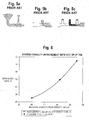
- Figure 6 shows a graph representing the expected efficiency improvements as a function of particulate densities. The high end improvement was documented at an experimental use of certain embodiments of the claimed invention at the Manitowac Public Utilities Station. System capacity in that instance improved from 8 tons per hour to 14 tons per hour with the installation of the new diffuser tees, without any change in the horsepower requirements for the system. The low end of the graph of Figure 6 is predicted based upon rough numbers from a further field test confirming the applicability of the claimed invention to finer particulate.
- the diffuser plate of the present invention can be automatically adjusted in a further alternative embodiment by a control system or systems to optimize conveying efficiency (e.g., by adjusting the trailing edge of the plate so that the length of the plate is not substantially parallel to the fluid flow, or by having an adjustable plate angle to accommodate possible multidirectional fluid flows).
- Parameters such as diffuser plate vertical location, length, and angle of the plate with respect to the conveying fluid can all be independently varied to increase efficiency.
Landscapes
- Engineering & Computer Science (AREA)
- Mechanical Engineering (AREA)
- Air Transport Of Granular Materials (AREA)
Applications Claiming Priority (1)
| Application Number | Priority Date | Filing Date | Title |
|---|---|---|---|
| US12/228,556 US7798749B2 (en) | 2008-08-14 | 2008-08-14 | High-efficiency material inlet with particulate diffuser plate for use in entraining particulate solids in a prime mover fluid |
Publications (2)
| Publication Number | Publication Date |
|---|---|
| EP2154092A2 true EP2154092A2 (fr) | 2010-02-17 |
| EP2154092A3 EP2154092A3 (fr) | 2012-05-02 |
Family
ID=41264218
Family Applications (1)
| Application Number | Title | Priority Date | Filing Date |
|---|---|---|---|
| EP09167898A Withdrawn EP2154092A3 (fr) | 2008-08-14 | 2009-08-14 | Dispositif d'alimentation en matériau à haut rendement pour le transport pneumatique de particules solides |
Country Status (2)
| Country | Link |
|---|---|
| US (1) | US7798749B2 (fr) |
| EP (1) | EP2154092A3 (fr) |
Cited By (1)
| Publication number | Priority date | Publication date | Assignee | Title |
|---|---|---|---|---|
| CN108602635A (zh) * | 2016-02-02 | 2018-09-28 | 精工爱普生株式会社 | 输送装置及薄片制造装置 |
Families Citing this family (9)
| Publication number | Priority date | Publication date | Assignee | Title |
|---|---|---|---|---|
| DE202009005561U1 (de) * | 2009-04-16 | 2009-07-02 | Fass, Wolfgang, Dipl.-Ing. | Vorrichtung und Anordnung zum Befüllen von Verarbeitungsstationen |
| MX341164B (es) * | 2011-10-27 | 2016-08-10 | Graco Minnesota Inc | Mecanismo de apoyo de alimentacion del sistema de vacio. |
| US9302857B2 (en) | 2012-04-25 | 2016-04-05 | Nordson Corporation | Pneumatic solids transfer pump |
| US20140263450A1 (en) * | 2013-03-12 | 2014-09-18 | Graco Minnesota Inc. | Feed system filters for a hot melt system |
| CN103604131B (zh) * | 2013-11-25 | 2016-01-13 | 镇江市电站辅机厂有限公司 | 悬吊式省煤器输灰系统 |
| CN108459641B (zh) | 2017-02-21 | 2021-05-04 | 固瑞克明尼苏达有限公司 | 适应性热熔供给系统 |
| RU2752704C1 (ru) * | 2017-08-31 | 2021-07-30 | Кимберли-Кларк Ворлдвайд, Инк. | Система для подачи зернистого материала с пневматическим приводом |
| US10709055B2 (en) * | 2018-05-24 | 2020-07-14 | Cnh Industrial Canada, Ltd. | Drop chute deflector for enhancing entrainment of granular product in an airstream of an agricultural product applicator |
| CN119822060A (zh) * | 2025-02-11 | 2025-04-15 | 四川优力赛新材料科技有限公司 | 一种固体颗粒输送装置及生产线 |
Citations (1)
| Publication number | Priority date | Publication date | Assignee | Title |
|---|---|---|---|---|
| US5775237A (en) | 1996-12-30 | 1998-07-07 | Florida Power Corporation | Dry bottom ash handling system |
Family Cites Families (30)
| Publication number | Priority date | Publication date | Assignee | Title |
|---|---|---|---|---|
| US1310815A (en) * | 1919-07-22 | Dusting-machin | ||
| US477692A (en) * | 1892-06-28 | Pneumatic conveyer | ||
| US724780A (en) * | 1902-07-05 | 1903-04-07 | Eugene Worthing | Pneumatic feeder. |
| US1207794A (en) * | 1912-08-23 | 1916-12-12 | W W Sly Mfg Company | Grading and transferring mechanism for granular material. |
| US1189328A (en) * | 1913-05-27 | 1916-07-04 | Ernest Williams | Soot and scale ejector. |
| US1901203A (en) * | 1931-02-09 | 1933-03-14 | Colorado Fuel And Iron Company | Coal feeder |
| US2586705A (en) * | 1948-02-14 | 1952-02-19 | Standard Oil Dev Co | Means for distributing solids in gases in catalytic apparatus |
| US2597323A (en) * | 1950-05-01 | 1952-05-20 | Hiller Helicopters | Crop dusting equipment |
| US2784038A (en) * | 1956-01-11 | 1957-03-05 | Dracco Corp | Means for pneumatically conveying plastic particulate material |
| US3115278A (en) * | 1961-01-05 | 1963-12-24 | H Ind Inc As | Fine solids handling device |
| US3206255A (en) * | 1963-10-01 | 1965-09-14 | Ronald E Gray | Pneumatic conveyor |
| US3436124A (en) * | 1966-05-21 | 1969-04-01 | Harry Smith | Treatment of granular,crushed,powdered or like materials |
| US3403942A (en) * | 1966-12-28 | 1968-10-01 | Rader Pneumatics & Eng Co Ltd | Particulate material feeding apparatus for fluid conveyor lines |
| US3809438A (en) * | 1973-03-22 | 1974-05-07 | Arbeck Ind Mining Equip | Pneumatic conveying apparatus |
| US4049405A (en) * | 1975-09-26 | 1977-09-20 | American Air Filter Company, Inc. | Filter material charging apparatus for filter assembly for radioactive contaminants |
| US4114954A (en) * | 1977-05-23 | 1978-09-19 | Falconbridge Nickel Mines Limited' | Hydraulic hoisting |
| US4420279A (en) * | 1982-02-22 | 1983-12-13 | Reactor Services International, Inc. | Pressure impulse dense phase conveying apparatus and method |
| US4569161A (en) * | 1983-11-03 | 1986-02-11 | Pennwalt Corporation | Pneumatic powder metering apparatus with improved powder throttling mechanism |
| DE3639139A1 (de) * | 1986-11-15 | 1988-05-26 | Praezisions Werkzeuge Ag | Verfahren zur erhoehung der ausgegebenen pulvermenge an einer pulverbeschichtungsanlage sowie pulverbeschichtungsanlage |
| US4938848A (en) * | 1989-02-13 | 1990-07-03 | Aluminum Company Of America | Method and apparatus for conveying split streams of alumina powder to an electrolysis cell |
| US5494381A (en) * | 1991-04-11 | 1996-02-27 | The Young Industries, Inc. | Apparatus and method for pneumatically conveying bulk materials |
| US5340241A (en) * | 1992-02-04 | 1994-08-23 | Motan, Inc. | Device for metering and entraining a product into a gas stream |
| US5575225A (en) * | 1995-02-27 | 1996-11-19 | Unverferth Manufacturing Company, Inc. | Air-powered apparatus for filling grain drills and method of using same |
| US5899641A (en) * | 1996-03-01 | 1999-05-04 | The Young Industries | Bulk material conveying system and ejector therefor |
| US6220791B1 (en) * | 1999-03-11 | 2001-04-24 | Board Of Trustees Of The University Of Arkansas | Apparatus and method for the aerosolization of powders |
| DE20201092U1 (de) * | 2002-01-24 | 2003-03-06 | Pfister Gmbh, 86165 Augsburg | Vorrichtung zum kontinuierlichen, gravimetrischen Dosieren und pneumatischen Fördern von Schüttgut |
| US6883736B1 (en) * | 2002-08-26 | 2005-04-26 | Michael Scott Blatt | Distribution assembly for particulate material |
| CA2420034C (fr) * | 2003-02-18 | 2007-09-25 | Jim Mcturk | Pompe a jet formant une boue aqueuse de sables bitumineux |
| US7270249B1 (en) * | 2005-03-03 | 2007-09-18 | Burkhead Ronnie J | Pneumatic metering apparatus for flowable solids product |
| EP1816095B1 (fr) * | 2006-02-07 | 2007-09-19 | IBAU Hamburg Ingenieurgesellschaft | Dispositif de transport pneumatique de matières pulvérulentes |
-
2008
- 2008-08-14 US US12/228,556 patent/US7798749B2/en not_active Expired - Fee Related
-
2009
- 2009-08-14 EP EP09167898A patent/EP2154092A3/fr not_active Withdrawn
Patent Citations (1)
| Publication number | Priority date | Publication date | Assignee | Title |
|---|---|---|---|---|
| US5775237A (en) | 1996-12-30 | 1998-07-07 | Florida Power Corporation | Dry bottom ash handling system |
Cited By (3)
| Publication number | Priority date | Publication date | Assignee | Title |
|---|---|---|---|---|
| CN108602635A (zh) * | 2016-02-02 | 2018-09-28 | 精工爱普生株式会社 | 输送装置及薄片制造装置 |
| EP3412607A4 (fr) * | 2016-02-02 | 2019-12-25 | Seiko Epson Corporation | Dispositif de transport et dispositif de fabrication de feuille |
| US11173627B2 (en) | 2016-02-02 | 2021-11-16 | Seiko Epson Corporation | Transport device and sheet manufacturing apparatus |
Also Published As
| Publication number | Publication date |
|---|---|
| US7798749B2 (en) | 2010-09-21 |
| US20100040422A1 (en) | 2010-02-18 |
| EP2154092A3 (fr) | 2012-05-02 |
Similar Documents
| Publication | Publication Date | Title |
|---|---|---|
| US7798749B2 (en) | High-efficiency material inlet with particulate diffuser plate for use in entraining particulate solids in a prime mover fluid | |
| RU70875U1 (ru) | Устройство для пневматического транспортирования | |
| US6155751A (en) | Flow development chamber for creating a vortex flow and a laminar flow | |
| CN102753460A (zh) | 主动式固体供应系统以及供应固体的方法 | |
| US7066207B2 (en) | Flow development chamber | |
| WO2011075456A1 (fr) | Système d'amenée de solides passif et procédé pour amener des solides | |
| US6659118B2 (en) | Flow development chamber | |
| US7082955B2 (en) | Axial input flow development chamber | |
| US20080175675A1 (en) | Low-pressure, air-based, particulate materials transfer apparatus and method | |
| CN107552252B (zh) | 餐厨垃圾用砂浆分离设备 | |
| CN210794376U (zh) | 一种粉末颗粒气力输送装置 | |
| CN101421484A (zh) | 用于从钻井液中除去固体的分离器和方法 | |
| CN209635162U (zh) | 溜槽疏通装置 | |
| CN104924184A (zh) | 一种自动除砂的纤维粉尘输送机以及除砂方法 | |
| CA2998019C (fr) | Procede et systeme pour recuperer de l'energie d'un ecoulement de boue de sables bitumineux | |
| CN201694657U (zh) | 一种气力输灰系统助推式自动防堵装置 | |
| US9525375B2 (en) | Oil sand slurry transportation system and method for variable slurry flow rates | |
| CN118434976A (zh) | 分配歧管 | |
| CN102893114B (zh) | 闪速炉速度控制设备 | |
| WO2020257476A1 (fr) | Transport de solides avec circuit de tuyauterie à diamètres multiples | |
| JP4743005B2 (ja) | ダスト回収設備及びダスト回収方法 | |
| JPH0891568A (ja) | 粉粒体の空気輸送の閉塞防止システム | |
| CN206798415U (zh) | 一种自清式粮食溜管倾斜管道缓冲装置 | |
| US20130322972A1 (en) | Pneumatic air conveyance technology | |
| JPH1149362A (ja) | 粉粒体の閉塞解除方法 |
Legal Events
| Date | Code | Title | Description |
|---|---|---|---|
| PUAI | Public reference made under article 153(3) epc to a published international application that has entered the european phase |
Free format text: ORIGINAL CODE: 0009012 |
|
| AK | Designated contracting states |
Kind code of ref document: A2 Designated state(s): AT BE BG CH CY CZ DE DK EE ES FI FR GB GR HR HU IE IS IT LI LT LU LV MC MK MT NL NO PL PT RO SE SI SK SM TR |
|
| AX | Request for extension of the european patent |
Extension state: AL BA RS |
|
| PUAL | Search report despatched |
Free format text: ORIGINAL CODE: 0009013 |
|
| RIC1 | Information provided on ipc code assigned before grant |
Ipc: B65G 53/14 20060101ALI20120319BHEP Ipc: B65G 53/10 20060101AFI20120319BHEP |
|
| AK | Designated contracting states |
Kind code of ref document: A3 Designated state(s): AT BE BG CH CY CZ DE DK EE ES FI FR GB GR HR HU IE IS IT LI LT LU LV MC MK MT NL NO PL PT RO SE SI SK SM TR |
|
| AX | Request for extension of the european patent |
Extension state: AL BA RS |
|
| 17P | Request for examination filed |
Effective date: 20121101 |
|
| 17Q | First examination report despatched |
Effective date: 20121205 |
|
| GRAP | Despatch of communication of intention to grant a patent |
Free format text: ORIGINAL CODE: EPIDOSNIGR1 |
|
| INTG | Intention to grant announced |
Effective date: 20140606 |
|
| RIN1 | Information on inventor provided before grant (corrected) |
Inventor name: RASTOGI, SAURABH Inventor name: JONES, ROBERT T. Inventor name: TRYBA, STANLEY R. Inventor name: CHARHUT, DANIEL E. |
|
| STAA | Information on the status of an ep patent application or granted ep patent |
Free format text: STATUS: THE APPLICATION IS DEEMED TO BE WITHDRAWN |
|
| 18D | Application deemed to be withdrawn |
Effective date: 20141017 |