EP2154183A1 - Beschichtete Substrate und Verfahren zu ihrer Herstellung - Google Patents
Beschichtete Substrate und Verfahren zu ihrer Herstellung Download PDFInfo
- Publication number
- EP2154183A1 EP2154183A1 EP20090169991 EP09169991A EP2154183A1 EP 2154183 A1 EP2154183 A1 EP 2154183A1 EP 20090169991 EP20090169991 EP 20090169991 EP 09169991 A EP09169991 A EP 09169991A EP 2154183 A1 EP2154183 A1 EP 2154183A1
- Authority
- EP
- European Patent Office
- Prior art keywords
- coating
- silicone resin
- interfacial
- sio
- inorganic barrier
- Prior art date
- Legal status (The legal status is an assumption and is not a legal conclusion. Google has not performed a legal analysis and makes no representation as to the accuracy of the status listed.)
- Withdrawn
Links
- 0 [*+][C@@]1CC2OC2CC1 Chemical compound [*+][C@@]1CC2OC2CC1 0.000 description 1
Images
Classifications
-
- C—CHEMISTRY; METALLURGY
- C08—ORGANIC MACROMOLECULAR COMPOUNDS; THEIR PREPARATION OR CHEMICAL WORKING-UP; COMPOSITIONS BASED THEREON
- C08J—WORKING-UP; GENERAL PROCESSES OF COMPOUNDING; AFTER-TREATMENT NOT COVERED BY SUBCLASSES C08B, C08C, C08F, C08G or C08H
- C08J7/00—Chemical treatment or coating of shaped articles made of macromolecular substances
- C08J7/04—Coating
- C08J7/042—Coating with two or more layers, where at least one layer of a composition contains a polymer binder
- C08J7/0423—Coating with two or more layers, where at least one layer of a composition contains a polymer binder with at least one layer of inorganic material and at least one layer of a composition containing a polymer binder
-
- C—CHEMISTRY; METALLURGY
- C08—ORGANIC MACROMOLECULAR COMPOUNDS; THEIR PREPARATION OR CHEMICAL WORKING-UP; COMPOSITIONS BASED THEREON
- C08J—WORKING-UP; GENERAL PROCESSES OF COMPOUNDING; AFTER-TREATMENT NOT COVERED BY SUBCLASSES C08B, C08C, C08F, C08G or C08H
- C08J7/00—Chemical treatment or coating of shaped articles made of macromolecular substances
- C08J7/04—Coating
- C08J7/048—Forming gas barrier coatings
-
- H—ELECTRICITY
- H10—SEMICONDUCTOR DEVICES; ELECTRIC SOLID-STATE DEVICES NOT OTHERWISE PROVIDED FOR
- H10P—GENERIC PROCESSES OR APPARATUS FOR THE MANUFACTURE OR TREATMENT OF DEVICES COVERED BY CLASS H10
- H10P14/00—Formation of materials, e.g. in the shape of layers or pillars
- H10P14/60—Formation of materials, e.g. in the shape of layers or pillars of insulating materials
- H10P14/63—Formation of materials, e.g. in the shape of layers or pillars of insulating materials characterised by the formation processes
- H10P14/6326—Deposition processes
- H10P14/6342—Liquid deposition, e.g. spin-coating, sol-gel techniques or spray coating
-
- H—ELECTRICITY
- H10—SEMICONDUCTOR DEVICES; ELECTRIC SOLID-STATE DEVICES NOT OTHERWISE PROVIDED FOR
- H10P—GENERIC PROCESSES OR APPARATUS FOR THE MANUFACTURE OR TREATMENT OF DEVICES COVERED BY CLASS H10
- H10P14/00—Formation of materials, e.g. in the shape of layers or pillars
- H10P14/60—Formation of materials, e.g. in the shape of layers or pillars of insulating materials
- H10P14/65—Formation of materials, e.g. in the shape of layers or pillars of insulating materials characterised by treatments performed before or after the formation of the materials
- H10P14/6516—Formation of materials, e.g. in the shape of layers or pillars of insulating materials characterised by treatments performed before or after the formation of the materials of treatments performed after formation of the materials
- H10P14/6536—Formation of materials, e.g. in the shape of layers or pillars of insulating materials characterised by treatments performed before or after the formation of the materials of treatments performed after formation of the materials by exposure to radiation, e.g. visible light
- H10P14/6538—Formation of materials, e.g. in the shape of layers or pillars of insulating materials characterised by treatments performed before or after the formation of the materials of treatments performed after formation of the materials by exposure to radiation, e.g. visible light by exposure to UV light
-
- H—ELECTRICITY
- H10—SEMICONDUCTOR DEVICES; ELECTRIC SOLID-STATE DEVICES NOT OTHERWISE PROVIDED FOR
- H10P—GENERIC PROCESSES OR APPARATUS FOR THE MANUFACTURE OR TREATMENT OF DEVICES COVERED BY CLASS H10
- H10P14/00—Formation of materials, e.g. in the shape of layers or pillars
- H10P14/60—Formation of materials, e.g. in the shape of layers or pillars of insulating materials
- H10P14/66—Formation of materials, e.g. in the shape of layers or pillars of insulating materials characterised by the type of materials
- H10P14/668—Formation of materials, e.g. in the shape of layers or pillars of insulating materials characterised by the type of materials the materials being characterised by the deposition precursor materials
- H10P14/6681—Formation of materials, e.g. in the shape of layers or pillars of insulating materials characterised by the type of materials the materials being characterised by the deposition precursor materials the precursor containing a compound comprising Si
- H10P14/6684—Formation of materials, e.g. in the shape of layers or pillars of insulating materials characterised by the type of materials the materials being characterised by the deposition precursor materials the precursor containing a compound comprising Si the compound comprising silicon and oxygen
- H10P14/6686—Formation of materials, e.g. in the shape of layers or pillars of insulating materials characterised by the type of materials the materials being characterised by the deposition precursor materials the precursor containing a compound comprising Si the compound comprising silicon and oxygen the compound being a molecule comprising at least one silicon-oxygen bond and the compound having hydrogen or an organic group attached to the silicon or oxygen, e.g. a siloxane
-
- H—ELECTRICITY
- H10—SEMICONDUCTOR DEVICES; ELECTRIC SOLID-STATE DEVICES NOT OTHERWISE PROVIDED FOR
- H10P—GENERIC PROCESSES OR APPARATUS FOR THE MANUFACTURE OR TREATMENT OF DEVICES COVERED BY CLASS H10
- H10P14/00—Formation of materials, e.g. in the shape of layers or pillars
- H10P14/60—Formation of materials, e.g. in the shape of layers or pillars of insulating materials
- H10P14/69—Inorganic materials
- H10P14/692—Inorganic materials composed of oxides, glassy oxides or oxide-based glasses
- H10P14/6921—Inorganic materials composed of oxides, glassy oxides or oxide-based glasses containing silicon
- H10P14/6922—Inorganic materials composed of oxides, glassy oxides or oxide-based glasses containing silicon the material containing Si, O and at least one of H, N, C, F or other non-metal elements, e.g. SiOC, SiOC:H or SiONC
-
- Y—GENERAL TAGGING OF NEW TECHNOLOGICAL DEVELOPMENTS; GENERAL TAGGING OF CROSS-SECTIONAL TECHNOLOGIES SPANNING OVER SEVERAL SECTIONS OF THE IPC; TECHNICAL SUBJECTS COVERED BY FORMER USPC CROSS-REFERENCE ART COLLECTIONS [XRACs] AND DIGESTS
- Y10—TECHNICAL SUBJECTS COVERED BY FORMER USPC
- Y10T—TECHNICAL SUBJECTS COVERED BY FORMER US CLASSIFICATION
- Y10T428/00—Stock material or miscellaneous articles
- Y10T428/31504—Composite [nonstructural laminate]
- Y10T428/31652—Of asbestos
- Y10T428/31663—As siloxane, silicone or silane
Definitions
- the present invention relates to coated substrates and more particularly to coated substrates comprising an inorganic barrier coating and an interfacial coating, wherein the interfacial coating comprises a cured product of a silicone resin having silicon-bonded radiation-sensitive groups.
- the present invention also relates to methods of preparing the coated substrates.
- Barrier coatings play an important role in a wide range of applications including electronic packaging, food packaging, and surface treatment, by protecting sensitive materials from air, moisture, and environmental contaminants.
- barrier coatings are frequently applied to polymer substrates to reduce the transmission rates of various gases and liquids through these permeable materials. As a result, such coatings increase the reliability and useful lifespan of many consumer products.
- Barrier coatings comprising a single layer of an inorganic material, such as a metal oxide or nitride are known in the art. However, such coatings are often too brittle for use on materials having high thermal expansion, such as polymer substrates. Stresses develop in the barrier layer due to differences in the coefficients of thermal expansion between the substrate and the coating. Thermally induced stresses can cause cracking of the barrier coating, thereby reducing the effectiveness of the coating.
- One approach to reducing crack formation in barrier coatings is to deposit an organic coating adjacent to the barrier coating.
- These multilayer coatings typically comprise alternating layers of inorganic and polymer materials.
- International Application Publication No. WO 03/016589 A1 to Czeremuszkin et al. discloses a multilayer structure comprising an organic substrate layer, and a mutilayer permeation barrier thereon, the barrier comprising a) a first inorganic coating contacting a surface of the substrate layer, and b) a first organic coating contacting a surface of the inorganic coating.
- U.S. Patent Application Publication No. US2003/0203210 A1 to Graff et al discloses a multi-layer barrier coating on a flexible substrate comprising alternating polymer and inorganic layers, wherein the layer immediately adjacent to the flexible substrate and the topmost isolation layer may both be inorganic layers.
- EP1139453 A2 discloses, inter alia , a self-light emitting device having an EL element, comprising a film that is made of an inorganic material covering said EL element, and a film that is made of an organic material covering said film made of an inorganic material.
- U.S. Patent No. 5,952,778 to Haskal et al discloses an encapsulated organic light emitting device having an improved protective covering comprising a first layer of passivating metal, a second layer of an inorganic dielectric material and a third layer of polymer.
- U.S. Patent No. 6,570,352 B2 to Graff et al discloses an encapsulated organic light emitting device comprising a substrate; an organic light emitting layer stack adjacent to the substrate; and at least one first barrier stack adjacent to the organic light emitting device, the at least one first barrier stack comprising at least one first barrier layer and at least one first decoupling layer, wherein the at least one first barrier stack encapsulates the organic light emitting device.
- the present invention is directed to a coated substrate, comprising:
- the present invention is also directed to a method of preparing the aforementioned coated substrate, the method comprising the steps of:
- the present invention is further directed to a coated substrate, comprising:
- the present invention is still further directed to a method of preparing the immediately preceding coated substrate, the method comprising the steps of:
- the composite inorganic barrier and interfacial coatings of the coated substrate have a low water vapor transmission rate, typically from 1 x 10 -7 to 3 g/m 2 /day. Also, the coatings have low permeability to oxygen and metal ions, such as copper and aluminum. Further, the coatings can be transparent or nontransparent to light in the visible region of the electromagnetic spectrum. Still further, the coatings have high resistance to cracking and low compressive stress.
- the methods of the present invention can be carried out using conventional equipment and techniques, and readily available silicone compositions.
- inorganic barrier coatings can be deposited using chemical vapor deposition techniques and physical vapor deposition techniques.
- interfacial coatings can be formed using conventional methods of applying and curing silicone compositions.
- the methods of the present invention are scaleable to high throughput manufacturing processes.
- coated substrates of the present invention are useful in applications requiring substrates having high resistance to water vapor and oxygen.
- the coated substrates can be used as a support for, or as an integral component of numerous electronic devices, including semiconductor devices, liquid crystals, light-emitting diodes, organic light-emitting diodes, optoelectronic devices, optical devices, photovoltaic cells, thin film batteries, and solar cells.
- the coated substrate can be a coated or encapsulated electronic device.
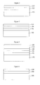
- Figure 1 shows a cross-sectional view of a first embodiment of a coated substrate according the present invention.
- Figure 2 shows a cross-sectional view of the first embodiment of the coated substrate, further comprising an additional inorganic barrier coating on the interfacial coating.
- Figure 3 shows a cross-sectional view of the first embodiment of the coated substrate, further comprising at least two alternating inorganic barrier and interfacial coatings on the interfacial coating.
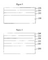
- Figure 4 shows a cross-sectional view of a second embodiment of a coated substrate according the present invention.
- Figure 5 shows a cross-sectional view of the second embodiment of the coated substrate, further comprising an additional interfacial coating on the inorganic barrier coating.
- Figure 6 shows a cross-sectional view of the second embodiment of the coated substrate, further comprising at least two alternating interfacial and inorganic barrier coatings on the inorganic barrier coating.
- the term "epoxy-substituted organic group” refers to a monovalent organic group in which an oxygen atom, the epoxy substituent, is directly attached to two adjacent carbon atoms of a carbon chain or ring system.
- mol% of the groups R 3 in the silicone resin are radiation-sensitive groups is defined as the ratio of the number of moles of silicon-bonded radiation-sensitive groups in the silicone resin to the total number of moles of the groups R 3 in the resin, multiplied by 100.
- a first embodiment of a coated substrate comprises a substrate 100, an inorganic barrier coating 102 on the substrate 100 ; and an interfacial coating 104 on the inorganic barrier coating 102 , wherein the interfacial coating 104 comprises a cured product of a silicone resin having the formula (R 1 R 3 2 SiO 1/2 ) a (R 3 2 SiO 2/2 ) b (R 3 SiO 3/2 ) c (SiO 4/2 ) d (I), wherein each R 1 is independently C 1 to C 10 hydrocarbyl, C 1 to C 10 halogen-substituted hydrocarbyl, or -OR 2 , wherein R 2 is C 1 to C 10 hydrocarbyl or C 1 to C 10 halogen-substituted hydrocarbyl, each R 3 is independently R 1 -H, or a radiation-sensitive group, a is from 0 to 0.95, b is from 0 to 0.95, c is from
- the substrate can be any rigid or flexible material having a planar, complex, or irregular contour.
- the substrate can be transparent or nontransparent to light in the visible region ( ⁇ 400 to ⁇ 700 nm) of the electromagnetic spectrum.
- the substrate can be an electrical conductor, semiconductor, or nonconductor.
- the substrate can be an electronic device, such as a discrete device and an integrated circuit.
- substrates include, but are not limited to, semiconductors such as silicon, silicon having a surface layer of silicon dioxide, silicon carbide, indium phosphide, and gallium arsenide; quartz; fused quartz; aluminum oxide; ceramics; glass; metal foils; polyolefins such as polyethylene, polypropylene, polystyrene, polyethylene terephthalate (PET), and polyethylene naphthalate; fluorocarbon polymers such as polytetrafluoroethylene and polyvinylfluoride; polyamides such as Nylon; polyimides; polyesters such as poly(methyl methacrylate); epoxy resins; polyethers; polycarbonates; polysulfones; and polyether sulfones.
- semiconductors such as silicon, silicon having a surface layer of silicon dioxide, silicon carbide, indium phosphide, and gallium arsenide
- quartz fused quartz
- aluminum oxide ceramics
- glass glass
- metal foils such as polyethylene, polypropylene, poly
- discrete devices include, but are not limited to, diodes, such as PIN diodes, voltage reference diodes, varactor diodes, Avalanche diodes, DIACs, Gunn diodes, Snap diodes, IMPATT diodes, tunnel diodes, Zener diodes, normal (p-n) diodes, and Shottky diodes; transistors, such as bipolar transistors, including, insulated gate bipolar transistors (IGBTs) and Darlington transistors, and field-effect transistors (FETs), including metal oxide semiconductor FETs (MOSFETs), junction FETs (JFETs), metal-semiconductor FETs (MESFETs), organic FETs, high electron mobility transistors (HEMTs), and thin film transistors (TFTs), including organic field effect transistors; thyristors, for example, DIACs, TRIACs, silicon controlled rectifiers (SCRs), distributed buffer-gate turn-off (DB-GTO) thyristor
- integrated circuits include, but are not limited to, monolithic integrated circuits, such as memory ICs, including RAM (random-access memory), including DRAM and SRAM, and ROM (read-only memory); logic circuits; analog integrated circuits; hybrid integrated circuits, including thin-film hybrid ICs and thick-film hybrid ICs; thin film batteries; and fuel cells.
- memory ICs including RAM (random-access memory), including DRAM and SRAM, and ROM (read-only memory); logic circuits; analog integrated circuits; hybrid integrated circuits, including thin-film hybrid ICs and thick-film hybrid ICs; thin film batteries; and fuel cells.
- the inorganic barrier coating can be any barrier coating comprising an inorganic material having a low permeability to water vapor (moisture).
- the inorganic material can be an electrical conductor, nonconductor, or semiconductor.
- the inorganic barrier coating can be a single layer coating comprising one layer of an inorganic material or a multiple layer coating comprising two or more layers of at least two different inorganic materials, where directly adjacent layers comprise different inorganic materials (i.e., inorganic materials have a different composition and/or property).
- the layer of inorganic material in a single layer coating comprises two or more elements (e.g. TiN)
- the layer can be a gradient layer, where the composition of the layer changes with thickness.
- the layer can be a gradient layer.
- the multiple layer coating typically comprises from 2 to 7 layers, alternatively from 2 to 5 layers, alternatively from 2 to 3 layers.
- the single layer inorganic barrier coating typically has a thickness of from 0.03 to 3 ⁇ m, alternatively from 0. 1 to 1 ⁇ m, alternatively from 0.2 to 0.8 ⁇ m.
- the multiple layer inorganic barrier coating typically has a thickness of from 0.06 to 5 ⁇ m, alternatively from 0.1 to 3 ⁇ m, alternatively from 0.2 to 2.5 ⁇ m.
- the thickness of the inorganic barrier coating is less than 0.03 ⁇ m, the permeability of the coating to moisture may be too high for some applications.
- the thickness of the inorganic barrier coating is greater than 5 ⁇ m, the inorganic barrier coating may be susceptible to cracking.
- the inorganic barrier coating may be transparent or nontransparent to light in the visible region ( ⁇ 400 to ⁇ 700 nm) of the electromagnetic spectrum.
- a transparent inorganic barrier coating typically has a percent transmittance of at least 30%, alternatively at least 60%, alternatively at least 80%, for light in the visible region of the electromagnetic spectrum.
- inorganic materials include, but are not limited to, metals such as aluminum, calcium, magnesium, nickel, and gold; metal alloys such as aluminum magnesium alloy, silver magnesium alloy, lithium aluminum alloy, indium magnesium alloy, and aluminum calcium alloy; oxides such as silicon dioxide, aluminum oxide, titanium(II) oxide, titanium(III) oxide, barium oxide, beryllium oxide, magnesium oxide, tin(II) oxide, tin(IV) oxide, indium(III) oxide, lead(II) oxide, lead(IV) oxide, zinc oxide, tantalum(V) oxide, yttrium(III) oxide, phosphorus pentoxide, boric oxide, zirconium(IV) oxide, and calcium oxide; mixed oxides such as indium tin oxide (ITO), indium zinc oxide (IZO), and indium cerium oxide; nitrides such as silicon nitride, titanium nitride, aluminum nitride, indium(III) nitride, and gallium nitride; mixed oxides
- the inorganic barrier coating can be formed as described below in the method of preparing the first embodiment of the coated substrate.
- the term "cured product of a silicone resin” refers to a cross-linked silicone resin having a three-dimensional network structure.
- the interfacial coating can be a single layer coating comprising one layer of a cured product of a silicone resin having the formula (I), or a multiple layer coating comprising two or more layers of at least two different cured products of silicone resins having the formula (I), where directly adjacent layers comprise different cured products (i.e., cured products have a different composition and/or property).
- the multiple layer coating typically comprises from 2 to 7 layers, alternatively from 2 to 5 layers, alternatively from 2 to 3 layers.
- the single layer interfacial coating typically has a thickness of from 0.03 to 30 ⁇ m, alternatively from 0.1 to 10 ⁇ m, alternatively from 0. 1 to 1.5 ⁇ m.
- the multiple layer interfacial coating typically has a thickness of from 0.06 to 30 ⁇ m, alternatively from 0.2 to 10 ⁇ m, alternatively 0.2 to 3 ⁇ m.
- the coating may become discontinuous.
- the thickness of the interfacial coating is greater than 30 ⁇ m, the coating may exhibit reduced adhesion and/or cracking.
- the interfacial coating typically exhibits high transparency.
- the interfacial coating typically has a percent transmittance of at least 90%, alternatively at least 92%, alternatively at least 94%, for light in the visible region ( ⁇ 400 to ⁇ 700 nm) of the electromagnetic spectrum.
- the silicone resin having the formula (I) can contain T siloxane units, T and Q siloxane units, or T and/or Q siloxane units in combination with M and/or D siloxane units.
- the silicone resin can be a T resin, a TQ resin, an MT resin, a DT resin, an MDT resin, an MQ resin, a DQ resin, an MDQ resin, an MTQ resin, a DTQ resin, or an MDTQ resin.
- the hydrocarbyl and halogen-substituted hydrocarbyl groups represented by R 1 and R 2 typically have from 1 to 10 carbon atoms, alternatively from 1 to 6 carbon atoms, alternatively from 1 to 4 carbon atoms.
- Acyclic hydrocarbyl and halogen-substituted hydrocarbyl groups containing at least 3 carbon atoms can have a branched or unbranched structure.
- hydrocarbyl groups include, but are not limited to, alkyl, such as methyl, ethyl, propyl, 1-methylethyl, butyl, 1-methylpropyl, 2-methylpropyl, 1,1-dimethylethyl, pentyl, 1-methylbutyl, 1-ethylpropyl, 2-methylbutyl, 3-methylbutyl, 1,2-dimethylpropyl, 2,2-dimethylpropyl, hexyl, heptyl, octyl, nonyl, and decyl; cycloalkyl, such as cyclopentyl, cyclohexyl, and methylcyclohexyl; aryl, such as phenyl and naphthyl; alkaryl, such as tolyl and xylyl; aralkyl, such as benzyl and phenethyl; alkenyl, such as vinyl, allyl, and propenyl; ary
- halogen-substituted hydrocarbyl groups include, but are not limited to, 3,3,3-trifluoropropyl, 3-chloropropyl, chlorophenyl, dichlorophenyl, 2,2,2-trifluoroethyl, 2,2,3,3-tetrafluoropropyl, and 2,2,3,3,4,4,5,5-octafluoropentyl.
- radiation-sensitive groups represented by R 3 include, but are not limited to, acryloyloxyalkyl, substituted acryloyloxyalkyl, an alkenyl ether group, alkenyl, and an epoxy-substituted organic group.
- radiation-sensitive group means the group forms a reactive species, for example a free radical or cation, in the presence of a free radical or cationic photoinitiator when exposed to radiation having a wavelength of from 150 to 800 nm.
- acryloyloxyalkyl groups represented by R 3 include, but are not limited to, acryloyloxymethyl, 2-acryloyloxyethyl, 3-acryloyloxyypropyl, and 4-acryloyloxybutyl.
- substituted acryloyloxyalkyl groups represented by R 3 include, but are not limited to, methacryloyloxymethyl, 2-methacryloyloxyethyl, and 3-methacryloyloxylpropyl.
- the hydrocarbylene groups represented by R 4 typically have from 1 to 10 carbon atoms, alternatively from 1 to 6 carbon atoms, alternatively from 1 to 4 carbon atoms.
- hydrocarbylene groups include, but are not limited to, alkylene such as methylene, ethylene, propane-1,3-diyl, 2-methylpropane-1,3-diyl, butane-1,4-diyl, butane-1,3-diyl, pentane-1,5,-diyl, pentane-1,4-diyl, hexane-1,6-diyl, octane-1,8-diyl, and decane-1,10-diyl; cycloalkylene such as cyclohexane-1,4-diyl; arylene such as phenylene.
- halogen-substituted hydrocarbylene groups include, but are not limited to, divalent hydrocarbon groups wherein one or more hydrogen atoms have been replaced by halogen, such as fluorine, chlorine, and bromine, such as -CH 2 CH 2 CF 2 CF 2 CH 2 CH 2 -.
- alkenyl groups represented by R 3 include, but are not limited to, vinyl, allyl, propenyl, butenyl, and hexenyl.
- Examples of epoxy-substituted organic groups represented by R 3 include, but are not limited to, 2,3-epoxypropyl, 3,4-epoxybutyl, 4,5-epoxypentyl, 2-glycidoxyethyl, 3-glycidoxypropyl, 4-glycidoxybutyl, 2-(3,4-epoxycylohexyl)ethyl, 3-(3,4-epoxycylohexyl)propyl, 2-(3,4-epoxy-3-methylcylohexyl)-2-methylethyl, 2-(2,3-epoxycylopentyl)ethyl, and 3-(2,3 epoxycylopentyl)propyl.
- the subscripts a, b, c, and d are mole fractions.
- the subscript a typically has a value of from 0 to 0.95, alternatively from 0 to 0.8, alternatively from 0 to 0.2;
- the subscript b typically has a value of from 0 to 0.95, alternatively from 0 to 0.8, alternatively from 0 to 0.5;
- the subscript c typically has a value of from 0 to 1, alternatively from 0.3 to 1, alternatively from 0.5 to 1;
- the subscript d typically has a value of from 0 to 0.9, alternatively from 0 to 0.5, alternatively from 0 to 0.1;
- the sum c+d typically has value of from 0.1 to 1, alternatively from 0.2 to 1, alternatively from 0.5 to 1, alternatively 0.8 to 1.
- the silicone resin typically has a weight-average molecular weight (M w ) of from 500 to 1,000,000, alternatively from 1,000 to 100,000, alternatively from 1,000 to 50,000, alternatively from 1,000 to 20,000, alternatively form 1,000 to 10,000, where the molecular weight is determined by gel permeation chromatography employing a refractive index detector and polystyrene standards.
- M w weight-average molecular weight
- the silicone resin typically contains an average of at least two silicon-bonded radiation-sensitive groups per molecule. Generally, at least 50 mol%, alternatively at least 65 mol%, alternatively at least 80 mol% of the groups R 3 in the silicone resin are radiation-sensitive groups.
- silicone resins include, but are not limited to, resins having the following formulae:
- silicone resins having silicon-bonded radiation-sensitive groups are known in the art.
- silicone resins containing silicon-bonded acryloyloxyalkyl or substituted acryloyloxyalkyl groups can be prepared by co-hydrolyzing an acryloyloxyalkyl- or substituted-acryloyloxyalkylalkoxysilane and an alkoxysilane in the presence of an acidic or basic catalyst, as exemplified in U.S. Patent No. 5,738,976 and U.S. Patent No. 5,959,038 .
- such resins can be produced by co-hydrolyzing an acryloyloxyalkyl- or substituted-acryloyloxayalkylchlorosilane and at least one chlorosilane, as taught in U.S. Patent No. 4,568,566 .
- Silicone reins containing silicon-bonded alkenyl ether groups can be prepared by reacting an alkoxysilane with water in the presence of an acidic condensation catalyst and subsequently treating the reaction mixture with a hydroxy-substituted vinyl ether and a transesterification catalyst, as described in U.S. Patent No. 5,861,467 .
- silicone resins containing alkenyl ether groups can be prepared by reacting an alkoxysilane, water, and a hydroxy-substituted vinyl ether compound in the presence of a non-acidic condensation catalyst, and then treating the reaction mixture with a transesterification catalyst, as described in U.S. Patent No. 5,824,761 .
- Silicone resins containing silicon-bonded alkenyl groups can be prepared by cohydrolyzing the appropriate mixture of chlorosilane precursors in an organic solvent, such as toluene.
- aqueous hydrochloric acid and silicone hydrolyzate are separated and the hydrolyzate is washed with water to remove residual acid and heated in the presence of a mild condensation catalyst to "body" the resin to the requisite viscosity.
- the resin can be further treated with a condensation catalyst in an organic solvent to reduce the content of silicon-bonded hydroxy groups.
- silanes containing hydrolysable groups other than chloro such-Br, -I, -OCH 3 , -OC(O)CH 3 , -N(CH 3 ) 2 , NHCOCH 3 , and -SCH 3 , can be utilized as starting materials in the cohydrolysis reaction.
- the properties of the resin products depend on the types of silanes, the mole ratio of silanes, the degree of condensation, and the processing conditions.
- Silicone resins containing silicon-bonded epoxy-substituted organic groups can be prepared by cohydrolyzing an epoxy-functional alkoxysilane and an alkoxysilane in the presence of an organotitanate catalyst, as described in U.S. Patent No. 5,468,826 .
- silicone resins containing silicon-bonded epoxy-substituted organic groups can be prepared by reacting a silicone resin containing silicon-bonded hydrogen atoms with an epoxy-functional alkene in the presence of a hydrosilylation catalyst, as described in U.S. Patent Nos.
- the interfacial coating can be formed as described below in the method of preparing the first embodiment of the coated substrate.
- the first embodiment of the coated substrate can further comprise an additional inorganic barrier coating 106 on the interfacial coating 104 .
- the additional inorganic barrier coating 106 is as described and exemplified above for the inorganic barrier coating 102 of the first embodiment of the coated substrate.
- the first embodiment of the coated substrate can further comprise at least two (three shown) alternating inorganic barrier 108 and interfacial 110 coatings on the interfacial coating 104 , wherein each alternating interfacial coating 110 comprises a cured product of a silicone resin having the formula (I).
- the alternating inorganic barrier 108 and alternating interfacial 110 coatings are as described above for the inorganic barrier 102 and interfacial 104 coatings of the first embodiment of the coated substrate.
- the first embodiment of the coated substrate can be prepared by forming an inorganic barrier coating on a substrate; and forming an interfacial coating on the inorganic barrier coating, wherein the interfacial coating comprises a cured product of a silicone resin having the formula (I).
- an inorganic barrier coating is formed on a substrate.
- the substrate and inorganic barrier coating are as described and exemplified above for the first embodiment of the coated substrate.
- inorganic barrier coatings can be deposited using chemical vapor deposition techniques, such as thermal chemical vapor deposition, plasma enhanced chemical vapor deposition, photochemical vapor deposition, electron cyclotron resonance, inductively coupled plasma, magnetically confined plasma, and jet vapor deposition; and physical vapor deposition techniques, such as RF sputtering, atomic layer deposition, and DC magnetron sputtering.
- chemical vapor deposition techniques such as thermal chemical vapor deposition, plasma enhanced chemical vapor deposition, photochemical vapor deposition, electron cyclotron resonance, inductively coupled plasma, magnetically confined plasma, and jet vapor deposition
- physical vapor deposition techniques such as RF sputtering, atomic layer deposition, and DC magnetron sputtering.
- an interfacial coating is formed on the inorganic barrier coating, wherein the interfacial coating comprises a cured product of a silicone resin having the formula (I).
- the interfacial coating is as described and exemplified above for the first embodiment of the coated substrate.
- the interfacial coating can be formed using a variety of methods.
- the interfacial coating can be formed by (i) applying a silicone composition comprising a silicone resin having the formula (I) on the inorganic barrier coating and (ii) curing the silicone resin.
- the silicone composition can be any silicone composition comprising a silicone resin having the formula (I), described and exemplified above.
- the silicone composition can comprise a single silicone resin or two or more different silicone resins, each having the formula (I).
- the silicone composition can comprise additional ingredients, provided the ingredient does not prevent the silicone resin from curing to form the interfacial layer, described above, of the coated substrate.
- additional ingredients include, but are not limited to, adhesion promoters; dyes; pigments; anti-oxidants; heat stabilizers; flame retardants; flow control additives; fillers, including extending and reinforcing fillers; organic solvents; cross-linking agents; photoinitiators; and organic peroxides.
- the silicone composition can further comprise at least one photoinitiator.
- the photoinitiator can be a cationic or free radical photoinitiator, depending on the nature of the radiation-sensitive groups in the silicone resin.
- the silicone composition can further comprise at least one cationic photoinitiator.
- the cationic photoinitiator can be any cationic photoinitiator capable of initiating cure (cross-linking) of the silicone resin upon exposure to radiation having a wavelength of from 150 to 800 nm.
- cationic photoinitiators include, but are not limited to, onium salts, diaryliodonium salts of sulfonic acids, triarylsulfonium salts of sulfonic acids, diaryliodonium salts of boronic acids, and triarylsulfonium salts of boronic acids.
- substituents on the hydrocarbyl group include, but are not limited to, C 1 to Cg alkoxy, C 1 to C 16 alkyl, nitro, chloro, bromo, cyano, carboxyl, mercapto, and heterocyclic aromatic groups, such as pyridyl, thiophenyl, and pyranyl.
- metals represented by M include, but are not limited to, transition metals, such as Fe, Ti, Zr, Sc, V, Cr, and Mn; lanthanide metals, such as Pr, and Nd; other metals, such as Cs, Sb, Sn, Bi, Al, Ga, and In; metalloids, such as B, and As; and P.
- the formula MX z - represents a non-basic, non-nucleophilic anion.
- onium salts include, but are not limited to, bis-diaryliodonium salts, such as bis(dodecyl phenyl)iodonium hexafluoroarsenate, bis(dodecylphenyl)iodonium hexafluoroantimonate, and dialkylphenyliodonium hexafluoroantimonate.
- bis-diaryliodonium salts such as bis(dodecyl phenyl)iodonium hexafluoroarsenate, bis(dodecylphenyl)iodonium hexafluoroantimonate, and dialkylphenyliodonium hexafluoroantimonate.
- diaryliodonium salts of sulfonic acids include, but are not limited to, diaryliodonium salts of perfluoroalkylsulfonic acids, such as diaryliodonium salts of perfluorobutanesulfonic acid, diaryliodonium salts of perfluoroethanesulfonic acid, diaryliodonium salts of perfluorooctanesulfonic acid, and diaryliodonium salts of trifluoromethanesulfonic acid; and diaryliodonium salts of aryl sulfonic acids, such as diaryliodonium salts of para-toluenesulfonic acid, diaryliodonium salts of dodecylbenzenesulfonic acid, diaryliodonium salts of benzenesulfonic acid, and diaryliodonium salts of 3-nitrobenzenesulfonic acid.
- triarylsulfonium salts of sulfonic acids include, but are not limited to, triarylsulfonium salts of perfluoroalkylsulfonic acids, such as triarylsulfonium salts of perfluorobutanesulfonic acid, triarylsulfonium salts of perfluoroethanesulfonic acid, triarylsulfonium salts of perfluorooctanesulfonic acid, and triarylsulfonium salts of trifluoromethanesulfonic acid; and triarylsulfonium salts of aryl sulfonic acids, such as triarylsulfonium salts of para-toluenesulfonic acid, triarylsulfonium salts of dodecylbenzenesulfonic acid, triarylsulfonium salts of benzenesulfonic acid, and triarylsulfonium salts of
- diaryliodonium salts of boronic acids include, but are not limited to, diaryliodonium salts of perhaloarylboronic acids.
- triarylsulfonium salts of boronic acids include, but are not limited to, triarylsulfonium salts of perhaloarylboronic acid.
- Diaryliodonium salts of boronic acids and triarylsulfonium salts of boronic acids are well known in the art, as exemplified in European Patent Application No. EP 0562922 .
- the cationic photoinitiator can be a single cationic photoinitiator or a mixture comprising two or more different cationic photoinitiators, each as described above.
- the concentration of the cationic photoinitiator is typically from 0.01 to 20% (w/w), alternatively from 0.1 to 20% (w/w), alternatively from 0.1 to 5%, based on the weight of the silicone resin.
- the silicone composition can further comprise at least one free radical photoinitiator.
- the free radical photoinitiator can be any free radical photoinitiator capable of initiating cure (cross-linking) of the silicone resin upon exposure to radiation having a wavelength of from 150 to 800 nm.
- free radical photoinitiators include, but are not limited to, benzophenone; 4,4'-bis(dimethylamino)benzophenone; halogenated benzophenones; acetophenone; ⁇ -hydroxyacetophenone; chloro acetophenones, such as dichloroacetophenones and trichloroacetophenones; dialkoxyacetophenones, such as 2,2-diethoxyacetophenone; ⁇ -hydoxyalkylphenones, such as 2-hydroxy-2-methyl-1-phenyl-1-propanone and 1-hydroxycyclohexyl phenyl ketone; ⁇ -aminoalkylphenones, such as 2-methyl-4'-(methylthio)-2-morpholiniopropiophenone; benzoin; benzoin ethers, such as benzoin methyl ether, benzoin ethyl ether, and benzoin isobutyl ether; benzil ketals, such as
- the free radical photoinitiator can also be a polysilane, such as the phenylmethylpolysilanes defined by West in U.S. Pat. No. 4,260,780 , which is hereby incorporated by reference; the aminated methylpolysilanes defined by Baney et al. in U.S. Pat. No. 4,314,956 , which is hereby incorporated by reference; the methylpolysilanes of Peterson et al. in U.S. Pat. No. 4,276,424 , which is hereby incorporated by reference; and the polysilastyrene defined by West et al. in U.S. Pat. No. 4,324,901 , which is hereby incorporated by reference.
- a polysilane such as the phenylmethylpolysilanes defined by West in U.S. Pat. No. 4,260,780 , which is hereby incorporated by reference; the aminated methylpolysilanes defined by
- the free radical photoinitiator can be a single free radical photoinitiator or a mixture comprising two or more different free radical photoinitiators.
- the concentration of the free radical photoinitiator is typically from 0.1 to 20% (w/w), alternatively from 1 to 10% (w/w), based on the weight of the silicone resin.
- the silicone composition can further comprise at least one organic peroxide.
- organic peroxides include, diaroyl peroxides such as dibenzoyl peroxide, di-p-chlorobenzoyl peroxide, and bis-2,4-dichlorobenzoyl peroxide; dialkyl peroxides such as di-t-butyl peroxide and 2,5-dimethyl-2,5-di-(t-butylperoxy)hexane; diaralkyl peroxides such as dicumyl peroxide; alkyl aralkyl peroxides such as t-butyl cumyl peroxide and 1,4-bis(t-butylperoxyisopropyl)benzene; and alkyl aroyl peroxides such as t-butyl perbenz
- the organic peroxide can be a single peroxide or a mixture comprising two or more different peroxides.
- concentration of the organic peroxide is typically from 0.1 to 20% (w/w), alternatively from 1 to 10% (w/w), based on the weight of the silicone resin.
- the composition is typically prepared by combining the silicone resin and any optional ingredients in the stated proportions at ambient temperature. Mixing can be accomplished by any of the techniques known in the art such as milling, blending, and stirring, either in a batch or continuous process. The particular device is determined by the viscosity of the components and the viscosity of the final silicone composition.
- the silicone composition can be applied on the inorganic barrier coating using conventional methods such as spin-coating, dipping, spraying, and brushing.
- the silicone resin can be cured using a variety of methods, depending on whether the silicone composition contains a photoinitiator or an organic peroxide.
- the silicone resin can be cured by heating the resin at a temperature of from room temperature ( ⁇ 23 ⁇ 2 °C) to 250 °C, alternatively from room temperature to 200 °C, alternatively from room temperature to 1.80 °C, at atmospheric pressure.
- the silicone resin can be cured by exposing the resin to an electron beam.
- the accelerating voltage is from about 0.1 to 100 keV
- the vacuum is from about 14 to 10-3 Pa
- the electron current is from about 0.0001 to 1 ampere
- the power varies from about 0.1 watt to 1 kilowatt.
- the dose is typically from about 100 microcoulomb/cm 2 to 100 coulomb/cm 2 , alternatively from about 1 to 10 coulombs/cm 2 .
- the time of exposure is typically from about 10 seconds to 1 hour.
- the silicone resin can be cured by exposing the resin to radiation having a wavelength of from 150 to 800 nm, alternatively from 200 to 400 nm, at a dosage sufficient to cure (cross-link) the silicone resin.
- the light source is typically a medium pressure mercury-arc lamp.
- the dose of radiation is typically from 30 to 1,000 mJ/cm 2 , alternatively from 50 to 500 mJ/cm 2 .
- the film can be externally heated during or after exposure to radiation to enhance the rate and/or extent of cure.
- the silicone resin can be cured by exposing the resin to an electron beam, as described above, or by heating the film at a temperature of from room temperature ( ⁇ 23 ⁇ 2 °C) to 180 °C, for a period of from 0.05 to 1 h.
- the method of preparing the first embodiment of the coated substrate can further comprise forming an additional inorganic barrier coating on the interfacial coating.
- the method can further comprise forming at least two alternating inorganic barrier and interfacial coatings on the interfacial coating, wherein each alternating interfacial coating comprises a cured product of a silicone resin having the formula (I).
- the surface of the substrate, inorganic barrier coating, and/or interfacial coating described above can be physically or chemically treated prior to forming an inorganic barrier or interfacial coating thereon.
- surface treatments include, but are not limited to, solvent wash, corona discharge, plasma discharge, application of a primer, and physical roughening.
- a second embodiment of a coated substrate according to the present invention comprises a substrate 200; an interfacial coating 202 on the substrate 200, wherein the interfacial coating 202 comprises a cured product of a silicone resin having the formula (I); and an inorganic barrier coating 204 on the interfacial coating 202.
- the substrate, interfacial coating, and inorganic barrier coating are as described and exemplified above for the first embodiment of the coated substrate.
- the second embodiment of the coated substrate can further comprise an additional interfacial coating 206 on the inorganic barrier coating 204, wherein the additional interfacial coating 206 comprises a cured product of a silicone resin having the formula (I).
- the additional interfacial coating is as described and exemplified above for the interfacial coating of the first embodiment of the coated substrate.
- the second embodiment of the coated substrate can further comprise at least two (three shown) alternating interfacial 208 and inorganic barrier 210 coatings on the inorganic barrier coating 204, wherein each alternating interfacial coating 208 comprises a cured product of a silicone resin having the formula (I).
- the alternating interfacial and inorganic barrier coatings are as described and exemplified above for the interfacial and inorganic barrier coatings of the first embodiment of the coated substrate.
- the second embodiment of the coated substrate can be prepared by forming an interfacial coating on a substrate, wherein the interfacial coating comprises a cured product of a silicone resin having the formula (I); and forming an inorganic barrier coating on the interfacial coating.
- the interfacial coating can be formed by (i) applying a silicone composition comprising a silicone resin having the formula (I) on the substrate and (ii) curing the silicone resin.
- the silicone composition, method of applying the composition, and method of curing the silicone resin are as described above for the method of preparing the first embodiment of the coated substrate.
- the inorganic barrier coating can be formed on the interfacial coating using the methods described above for preparing the first embodiment of the coated substrate.
- the method of preparing the second embodiment of the coated substrate can further comprise forming an additional interfacial coating on the inorganic barrier coating, wherein the additional interfacial coating comprises a cured product of a silicone resin having the formula (I).
- the method can further comprise forming at least two alternating interfacial and inorganic barrier coatings on the inorganic barrier coating, wherein each alternating interfacial coating comprises a cured product of a silicone resin having the formula (I).
- the composite inorganic barrier and interfacial coatings of the coated substrate have a low water vapor transmission rate, typically from 1 x 10 -7 to 3 g/m 2 /day. Also, the coatings have low permeability to oxygen and metal ions, such as copper and aluminum. Further, the coatings can be transparent or nontransparent to light in the visible region of the electromagnetic spectrum. Still further, the coatings have high resistance to cracking and low compressive stress.
- the methods of the present invention can be carried out using conventional equipment and techniques, and readily available silicone compositions.
- inorganic barrier coatings can be deposited using chemical vapor deposition techniques and physical vapor deposition techniques.
- interfacial coatings can be formed using conventional methods of applying and curing silicone compositions.
- the methods of the present invention are scaleable to high throughput manufacturing processes.
- coated substrates of the present invention are useful in applications requiring substrates having high resistance to water vapor and oxygen.
- the coated substrates can be used as a support for, or as an integral component of numerous electronic devices, including semiconductor devices, liquid crystals, light-emitting diodes, organic light-emitting diodes, optoelectronic devices, optical devices, photovoltaic cells, thin film batteries, and solar cells.
- the coated substrate can be a coated or encapsulated electronic device.
- M W Weight-average molecular weight of silicone resins having radiation-sensitive groups were determined by gel permeation chromatography (GPC) using a PLgel (Polymer Laboratories, Inc.) 5- ⁇ m column at 35 °C, a THF mobile phase at 1 mL/min, and a refractive index detector. Polystyrene standards were used for a calibration curve (3 rd order). The M W of hydrogensilsesquioxane resins were determined in the same manner, only the mobile phase was toluene.
- the thickness and refractive index of barrier and interfacial coatings on silicon wafers were determined using a J.A. Woollam XLS-100 VASE Ellipsometer. The reported values for thickness, expressed in units of nm, represent the average of nine measurements performed on different regions of the same coated wafer. Refractive index was determined at 23 °C for light having a wavelength of 589 nm.
- KLA Tencor FLX-2320 KLA Tencor, Milpitas, CA
- Thin Film Stress Measurement System at a temperature of 18-22 °C.
- UV-Visible spectra 200-800 nm
- Background scans were performed with an empty sample chamber in air. Percent transmittance was calculated from absorbance values at 430 nm, 470 nm, 530 um, 550 nm, and 650 nm.
- Density of barrier layers comprising hydrogenated silicon oxycarbide was determined by measuring the mass, thickness, and surface area of a film deposited on a circular substrate having a diameter of 10.2 cm. The mass of a layer was determined using an analytical balance having an accuracy of 1 x 10 -5 g under ambient conditions (25 °C, 101.3 kPa).
- the deposition chamber was thoroughly cleaned before the preparation of each coated substrate by first plasma etching the interior surfaces of the chamber for 5 to 10 min. using a plasma generated from CF 4 and O 2 at a pressure of 40 Pa, a CF 4 flow rate of 500 sccm, an O 2 flow rate of 100 seem, an LF power of 40 W, and an RF power of 500 W. After plasma etching, the walls of the chamber were wiped with isopropyl alcohol, and dried with nitrogen.
- the inorganic barrier coatings (silicon carbide, hydrogenated silicon oxycarbide) were deposited using a Model No. 2212 HDP parallel plate chemical vapor deposition system from Applied Process Technologies (Tucson, Az) operating in a dual frequency mode at a substrate temperature of 25 °C, a pressure of 0.09 Torr (12.0 Pa), an RF power source connected to the top electrode (shower head) and an LF power source connected to the bottom electrode (substrate holder).
- Calcium was deposited on glass wafers to a thickness of 100 nm by thermal evaporation (upward technique) through a shadow mask having a 3 x 3 array of 1-in. square apertures using a BOC Edwards model E306A Coating System under an initial pressure of 10 -6 mbar.
- the coating system was equipped with a crystal balance film thickness monitor.
- the source was prepared by placing the metal in an aluminum oxide crucible and positioning the crucible in a tungsten wire spiral, or by placing the metal directly in a tungsten basket. The deposition rate (0.1 to 0.3 nm per second) and the thickness of the films were monitored during the deposition process.
- a 3 x 3 array of 1-in. square highly reflective metallic mirrors were produced on each glass wafer.
- Titanium nitride (TiN) was deposited on a layer of hydrogenated silicon oxycarbide (SiCOH) to a thickness of 100 nm using a Denton DV-502A sputtering system.
- SiCOH hydrogenated silicon oxycarbide
- argon was introduced into the chamber until the pressure reached 3 mTorr (0.4 Pa).
- a 95:5 (v/v) mixture of nitrogen and argon was introduced into the chamber while maintaining a pressure of 3 mTorr (0.4 Pa).
- the target shield was opened, the power was increased to 400 Watts, and TiN was reactively sputtered for 10 min.
- Darocur ® 4265 Photoinitiator a mixture of 50% of 2-hydroxy-2-methyl-1-phenyl-propan-1-one and 50% of 2,4,6-trimethylbenzoyldiphenyl-phosphine oxide, sold by CIBA Specialty Chemicals.
- UV 9380C Photoinitiator bis(dodecylphenyl)iodonium hexafluoroantimonate, sold by GE Toshiba Silicones.
- Irgacure® 819 Photoinitiator bis(2,4,6-trimethylbenzoyl)phenylphosphine oxide, sold by Ciba Specialty Chemicals.
- Pfaltz & Bauer T17775 Photoinitiator A solution of 50% of triarylsulfonium hexafluoroantimonate salts in propylene carbonate, sold by Pfaltz & Bauer (Waterbury, CT).
- a hydrogensilsesquioxane resin (26.68 g) having the formula (HSiO 3/2 ) and a weight-average molecular weight of 7,100,70 mL of toluene, and 10 ⁇ L (23% w/w platinum) of a solution of platinum(0)-1,3-divinyl-1,1,3,3-tetramethyldisiloxane complex in 1,3-divinyl-1,1,3,3-tetramethyldisiloxane were combined in a flask and heated to 80 °C. Allyl glycidyl ether (48.4 g) was then added drop-wise to the mixture over a period of about 1 h. After completion of the addition, the mixture was allowed to cool to room temperature.
- Concentrated hydrochloric acid (37%, 600 g), 1020 g of toluene, and 3.0 g of octylsulfonic acid sodium salt monohydrate were combined in a flask.
- a solution consisting of 90.75 g (0.67 mol) of trichlorosilane, 100.15 g (0.67 mol) of methyltrichlorosilane, and 6.14 g (0.038 mol) of trichlorovinylsilane was added drop-wise to the mixture over a period of abut 1 h. The mixture was stirred at room temperature for 4 h, after which time the aqueous layer was removed.
- toluene was added to the mixture to maintain a constant resin concentration.
- the temperature of the mixture was slowly increased to about 110 °C during about 1 h.
- the mixture was then allowed to cool to room temperature.
- Acetic acid (3.4 mL) was then added drop-wise to the stirred mixture over a period 1 h.
- the mixture was washed with 1,000 mL of deionized water (ten times) and then filtered. Toluene was removed under reduced pressure at 40 °C using a rotary evaporator.
- the mixture was heated at reflux and the progress of the reaction was monitored by periodically withdrawing an aliquot of the mixture for analysis by gas chromatography. After 2 h, the mixture was allowed to cool to room temperature and toluene and excess allyl glycidyl ether were removed under reduced pressure at 40 °C using a rotary evaporator. The residue was placed under vacuum (1 Pa) at room temperature overnight to give a silicone resin having the formula: as determined by 29 Si NMR and 13 C NMR, and a weight-average molecular weight of 8,000.
- the mixture was heated at reflux and the progress of the reaction was monitored by periodically withdrawing an aliquot of the mixture for analysis by gas chromatography. After 2 h, the mixture was allowed to cool to room temperature and toluene and excess allyl glycidyl ether were removed under reduced pressure at 40 °C using a rotary evaporator. The residue was placed under vacuum (1 Pa) at room temperature overnight to give a silicone resin having the formula; as determined by 29 Si NMR and 13 C NMR, and a weight-average molecular weight of 9,000.
- the mixture was heated at reflux and the progress of the reaction was monitored by periodically withdrawing an aliquot of the mixture for analysis by gas chromatography. After 5 h, the mixture was allowed to cool to room temperature and toluene and excess allyl glycidyl ether were removed under reduced pressure at 40 °C using a rotary evaporator. The residue was placed under vacuum (1 Pa) at room temperature overnight to give a silicone resin having the formula: as determined by 29 Si NMR and 13 C NMR, and a weight-average molecular weight of 6,000.
- coated substrates were prepared as described in Examples 11-16, except the silicon wafer was replaced with a 150-mm diameter Corning® 1737 glass wafer.
- the percent transmittance of the coated glass substrates are shown in Table 2.
- Example 23 the percent transmittance of an uncoated glass wafer was measured for comparison. Table 2 Ex.
- coated substrates were prepared as described in Examples 17-22, except calcium was first deposited on each glass wafer to a thickness of 100 nm by thermal evaporation (upward technique) through a shadow mask having a 3 x 3 array of 1-in. square apertures, as described above.
- the barrier and interfacial coatings of Examples 17-22 were then deposited on the calcium-coated glass wafer.
- the wafers were exposed to 30-50% RH at 20 °C and the percent transmittance of the calcium squares at 550 nm on each wafer was measured at regular intervals.
- the metallic calcium reacted over time to form an increasingly transparent layer of calcium oxides, hydroxides, and/or salts.
- the time in hours corresponding to a 10% and 30% increase in percent transmittance for each coated substrate is shown in Table 3.
- Table 3 Ex.
- the coated substrate according to the invention wherein the substrate is an electronic device.
- the coated substrate according to the invention wherein the radiation-sensitive group is selected from acryloyloxyalkyl, substituted acryloyloxyalkyl, an alkenyl ether group, alkenyl, and an epoxy-substituted organic group.
- coated substrate according to the invention further comprising an additional inorganic barrier coating on the interfacial coating.
- each alternating interfacial coating comprises a cured product of a silicone resin having the formula (I).
- a method of preparing a coated substrate comprising the steps of:
Landscapes
- Chemical & Material Sciences (AREA)
- Organic Chemistry (AREA)
- Health & Medical Sciences (AREA)
- Chemical Kinetics & Catalysis (AREA)
- Medicinal Chemistry (AREA)
- Polymers & Plastics (AREA)
- Inorganic Chemistry (AREA)
- Silicon Polymers (AREA)
- Laminated Bodies (AREA)
- Paints Or Removers (AREA)
- Application Of Or Painting With Fluid Materials (AREA)
- Electroluminescent Light Sources (AREA)
- Coating Of Shaped Articles Made Of Macromolecular Substances (AREA)
- Formation Of Insulating Films (AREA)
Applications Claiming Priority (2)
| Application Number | Priority Date | Filing Date | Title |
|---|---|---|---|
| US72368805P | 2005-10-05 | 2005-10-05 | |
| EP20060803778 EP1963409A2 (de) | 2005-10-05 | 2006-09-18 | Beschichtete substrate und herstellungsverfahren dafür |
Related Parent Applications (1)
| Application Number | Title | Priority Date | Filing Date |
|---|---|---|---|
| EP06803778.7 Division | 2006-09-18 |
Publications (1)
| Publication Number | Publication Date |
|---|---|
| EP2154183A1 true EP2154183A1 (de) | 2010-02-17 |
Family
ID=37814113
Family Applications (2)
| Application Number | Title | Priority Date | Filing Date |
|---|---|---|---|
| EP20090169991 Withdrawn EP2154183A1 (de) | 2005-10-05 | 2006-09-18 | Beschichtete Substrate und Verfahren zu ihrer Herstellung |
| EP20060803778 Withdrawn EP1963409A2 (de) | 2005-10-05 | 2006-09-18 | Beschichtete substrate und herstellungsverfahren dafür |
Family Applications After (1)
| Application Number | Title | Priority Date | Filing Date |
|---|---|---|---|
| EP20060803778 Withdrawn EP1963409A2 (de) | 2005-10-05 | 2006-09-18 | Beschichtete substrate und herstellungsverfahren dafür |
Country Status (6)
| Country | Link |
|---|---|
| US (1) | US20090130463A1 (de) |
| EP (2) | EP2154183A1 (de) |
| JP (1) | JP2009511290A (de) |
| CN (1) | CN101313392B (de) |
| TW (1) | TW200726798A (de) |
| WO (1) | WO2007044181A2 (de) |
Families Citing this family (30)
| Publication number | Priority date | Publication date | Assignee | Title |
|---|---|---|---|---|
| US8304085B2 (en) * | 2006-04-18 | 2012-11-06 | Dow Corning Corporation | Metal foil substrates coated with condensation cured silicone resin compositions |
| US20100051920A1 (en) * | 2006-12-20 | 2010-03-04 | Dow Corning Corporation | Composite Article Including a Cation-Sensitive Layer |
| KR20090107882A (ko) * | 2008-04-10 | 2009-10-14 | 삼성전자주식회사 | 고정층을 포함하는 경사 조성 봉지 박막 및 그의 제조방법 |
| JP5520528B2 (ja) * | 2008-07-10 | 2014-06-11 | 東レ・ダウコーニング株式会社 | ガスバリアー性硬化オルガノポリシロキサン樹脂フィルム及びその製造方法 |
| CN102159395B (zh) * | 2008-08-19 | 2014-09-10 | 琳得科株式会社 | 成型制品、其制备方法、电子设备构件以及电子设备 |
| US8491967B2 (en) | 2008-09-08 | 2013-07-23 | Applied Materials, Inc. | In-situ chamber treatment and deposition process |
| WO2010038709A1 (ja) * | 2008-09-30 | 2010-04-08 | 凸版印刷株式会社 | 反射防止フィルム |
| JP4863024B2 (ja) * | 2008-11-10 | 2012-01-25 | 信越化学工業株式会社 | ガスバリア膜形成用組成物、ガスバリア性積層体及びそれを用いた成形体 |
| CN102245379B (zh) * | 2008-12-12 | 2015-06-24 | 琳得科株式会社 | 叠层体、其制造方法、电子设备构件和电子设备 |
| KR20100071650A (ko) * | 2008-12-19 | 2010-06-29 | 삼성전자주식회사 | 가스차단성박막, 이를 포함하는 전자소자 및 이의 제조방법 |
| JP5379530B2 (ja) | 2009-03-26 | 2013-12-25 | リンテック株式会社 | 成形体、その製造方法、電子デバイス用部材および電子デバイス |
| JP5704610B2 (ja) | 2009-05-22 | 2015-04-22 | リンテック株式会社 | 成形体、その製造方法、電子デバイス用部材および電子デバイス |
| WO2011083879A1 (en) * | 2010-01-07 | 2011-07-14 | Dow Corning Toray Co., Ltd. | Cured organopolysiloxane resin film having gas barrier properties and method of producing the same |
| JP5697230B2 (ja) | 2010-03-31 | 2015-04-08 | リンテック株式会社 | 成形体、その製造方法、電子デバイス用部材及び電子デバイス |
| WO2012003416A1 (en) | 2010-07-02 | 2012-01-05 | 3M Innovative Properties Company | Barrier assembly |
| US9254506B2 (en) | 2010-07-02 | 2016-02-09 | 3M Innovative Properties Company | Moisture resistant coating for barrier films |
| KR20120008360A (ko) * | 2010-07-16 | 2012-01-30 | 삼성모바일디스플레이주식회사 | 플렉서블 디스플레이용 기판 및 그 제조 방법 |
| JP5750441B2 (ja) | 2010-08-20 | 2015-07-22 | リンテック株式会社 | 成形体、その製造方法、電子デバイス用部材及び電子デバイス |
| TWI535561B (zh) | 2010-09-21 | 2016-06-01 | 琳得科股份有限公司 | A molded body, a manufacturing method thereof, an electronic device element, and an electronic device |
| TWI457235B (zh) | 2010-09-21 | 2014-10-21 | Lintec Corp | A gas barrier film, a manufacturing method thereof, an electronic device element, and an electronic device |
| CN102468352A (zh) * | 2010-11-01 | 2012-05-23 | 武汉美格能源科技有限公司 | 一种高阻隔柔性背膜 |
| CN102340900A (zh) * | 2011-07-21 | 2012-02-01 | 佛山市海辰科技有限公司 | 基于ir-led陶瓷基板的稀土厚膜电路电热元件及其制备方法 |
| US9362527B2 (en) | 2012-02-15 | 2016-06-07 | Konica Minolta, Inc. | Functional film having a hybrid layer of polysiloxane and fine resin particles |
| US10787591B2 (en) * | 2012-04-30 | 2020-09-29 | The Boeing Company | Composites including silicon-oxy-carbide layers and methods of making the same |
| EP2882761B1 (de) * | 2012-08-08 | 2017-04-19 | 3M Innovative Properties Company | Harnstoff(multi)-urethan(meth)acrylat-silanzusammensetzungen und artikel damit |
| TWI610806B (zh) | 2012-08-08 | 2018-01-11 | 3M新設資產公司 | 障壁膜,製造該障壁膜之方法,及包含該障壁膜之物件 |
| WO2014157686A1 (ja) * | 2013-03-29 | 2014-10-02 | リンテック株式会社 | 積層体及びその製造方法、電子デバイス用部材、並びに電子デバイス |
| WO2015099461A1 (ko) * | 2013-12-24 | 2015-07-02 | 네오뷰코오롱 주식회사 | 유기전계발광소자 |
| CN106796978B (zh) * | 2014-06-25 | 2019-09-17 | 美国陶氏有机硅公司 | 层状聚合物结构和方法 |
| CN112349795B (zh) * | 2020-10-27 | 2022-03-25 | 嘉兴学院 | 一种表面吸附锂离子的范德华异质结光电二极管器件结构 |
Citations (15)
| Publication number | Priority date | Publication date | Assignee | Title |
|---|---|---|---|---|
| US5237439A (en) * | 1991-09-30 | 1993-08-17 | Sharp Kabushiki Kaisha | Plastic-substrate liquid crystal display device with a hard coat containing boron or a buffer layer made of titanium oxide |
| US5283309A (en) | 1991-11-20 | 1994-02-01 | Dow Corning Toray Silicone Co., Ltd. | Epoxy-containing organopolysiloxane and method for the preparation thereof |
| US5310843A (en) | 1991-10-17 | 1994-05-10 | Dow Corning Toray Silicone Co., Ltd. | Organopolysiloxane and method for the preparation thereof |
| US5358983A (en) | 1992-05-26 | 1994-10-25 | Dow Corning Toray Silicone Co., Ltd. | Curable silicone composition |
| WO1995000259A2 (en) * | 1993-06-21 | 1995-01-05 | Elf Atochem North America, Inc. | Brittle oxide substrates strengthened by cross-linkable silanes |
| US5468826A (en) | 1994-05-10 | 1995-11-21 | Dow Corning Corporation | Adhesion promoting additives and curable organosiloxane compositions containing same |
| US5468827A (en) | 1993-06-29 | 1995-11-21 | Dow Corning Toray Silicon Co., Ltd. | Epoxy-functional MQ organopolysiloxanes |
| US5530075A (en) | 1992-04-21 | 1996-06-25 | Dow Corning Toray Silicone Co., Ltd. | Curable resin composition |
| US5718967A (en) * | 1995-10-13 | 1998-02-17 | The Dow Chemical Company | Coated plastic substrate |
| JPH11302598A (ja) * | 1998-04-23 | 1999-11-02 | Nikon Corp | コーティング組成物及びコーティング組成物が塗布された成型体及びその製造方法 |
| US6136444A (en) * | 1995-02-02 | 2000-10-24 | Teijin Limited | Transparent conductive sheet |
| WO2003016589A1 (en) | 2001-08-20 | 2003-02-27 | Nova-Plasma Inc. | Coatings with low permeation of gases and vapors |
| EP1388593A2 (de) * | 2002-08-07 | 2004-02-11 | Schott Glas | Schnelles Verfahren zur Herstellung von Multilayer-Barriereschichten |
| US6831145B2 (en) | 2000-08-08 | 2004-12-14 | Dow Corning Corporation | Silicone composition and electrically conductive, cured silicone product |
| US20050118428A1 (en) | 2002-08-07 | 2005-06-02 | Matthias Bicker | Rapid process for the production of multilayer barrier layers |
Family Cites Families (24)
| Publication number | Priority date | Publication date | Assignee | Title |
|---|---|---|---|---|
| US4260780A (en) * | 1979-11-27 | 1981-04-07 | The United States Of America As Represented By The Secretary Of The Air Force | Phenylmethylpolysilane polymers and process for their preparation |
| US4276424A (en) * | 1979-12-03 | 1981-06-30 | Petrarch Systems | Methods for the production of organic polysilanes |
| US4314958A (en) * | 1980-07-22 | 1982-02-09 | Phillips Petroleum Company | Plastic pipe extrusion |
| US4324901A (en) * | 1981-04-29 | 1982-04-13 | Wisconsin Alumni Research Foundation | Soluble polysilastyrene and method for preparation |
| US4568566A (en) * | 1984-10-30 | 1986-02-04 | General Electric Company | Acrylic-functional silicone resin compositions |
| JP2544018B2 (ja) * | 1990-10-22 | 1996-10-16 | 信越化学工業株式会社 | 紫外線硬化性オルガノポリシロキサン組成物 |
| US5861467A (en) * | 1993-05-18 | 1999-01-19 | Dow Corning Corporation | Radiation curable siloxane compositions containing vinyl ether functionality and methods for their preparation |
| JP2541494B2 (ja) * | 1993-12-15 | 1996-10-09 | 日本電気株式会社 | 半導体装置 |
| US5738976A (en) * | 1995-03-16 | 1998-04-14 | Shin-Etsu Chemical Co., Ltd. | Photo-curable organopolysiloxane composition and a method for producing a (meth) acryloyloxyl group-containing organopolysiloxane used therein |
| JP3199598B2 (ja) * | 1995-03-16 | 2001-08-20 | 信越化学工業株式会社 | (メタ)アクリロイルオキシル基含有オルガノポリシロキサンの製造方法 |
| US5824761A (en) * | 1995-05-18 | 1998-10-20 | Dow Corning Corporation | Radiation curable compositions containing vinyl ether functionality and methods for their preparation |
| JP3730317B2 (ja) * | 1996-05-30 | 2006-01-05 | 東レ・ダウコーニング株式会社 | 人工大理石用熱硬化性樹脂組成物および人工大理石 |
| US5952778A (en) * | 1997-03-18 | 1999-09-14 | International Business Machines Corporation | Encapsulated organic light emitting device |
| US6069185A (en) * | 1998-11-25 | 2000-05-30 | Dow Corning Asia, Ltd. | Radiation curable compositions containing alkenyl ether functional polyisobutylenes |
| JP2000227603A (ja) * | 1998-11-30 | 2000-08-15 | Teijin Ltd | 液晶表示素子及びそれに好適な透明導電性基板 |
| US6136044A (en) * | 1999-02-03 | 2000-10-24 | Board Of Supervisors Of Louisiana State University And Agricultural And Mechanical College | Stable coloring by in situ formation of micro-particles |
| TWI226205B (en) | 2000-03-27 | 2005-01-01 | Semiconductor Energy Lab | Self-light emitting device and method of manufacturing the same |
| US6570352B2 (en) * | 2000-11-17 | 2003-05-27 | Nsk Ltd. | Control unit for electric power steering apparatus |
| US7077935B2 (en) | 2001-05-04 | 2006-07-18 | General Atomics | O2 and H2O barrier material |
| US20030203210A1 (en) | 2002-04-30 | 2003-10-30 | Vitex Systems, Inc. | Barrier coatings and methods of making same |
| US7288311B2 (en) * | 2003-02-10 | 2007-10-30 | Dai Nippon Printing Co., Ltd. | Barrier film |
| US20060158101A1 (en) * | 2003-03-04 | 2006-07-20 | Dow Corning Corporation | Organic light-emitting diode |
| JP2004361692A (ja) * | 2003-04-07 | 2004-12-24 | Dow Corning Asia Ltd | 光伝送部材用硬化性オルガノポリシロキサン樹脂組成物、オルガノポリシロキサン樹脂硬化物からなる光伝送部材および光伝送部材の製造方法 |
| JP4227040B2 (ja) * | 2004-03-03 | 2009-02-18 | 富士フイルム株式会社 | ガスバリア性積層フィルムおよび該フィルムを用いた画像表示素子 |
-
2006
- 2006-09-18 WO PCT/US2006/036265 patent/WO2007044181A2/en not_active Ceased
- 2006-09-18 JP JP2008534551A patent/JP2009511290A/ja active Pending
- 2006-09-18 CN CN2006800431294A patent/CN101313392B/zh not_active Expired - Fee Related
- 2006-09-18 EP EP20090169991 patent/EP2154183A1/de not_active Withdrawn
- 2006-09-18 EP EP20060803778 patent/EP1963409A2/de not_active Withdrawn
- 2006-09-18 US US11/992,871 patent/US20090130463A1/en not_active Abandoned
- 2006-10-02 TW TW095136601A patent/TW200726798A/zh unknown
Patent Citations (16)
| Publication number | Priority date | Publication date | Assignee | Title |
|---|---|---|---|---|
| US5237439A (en) * | 1991-09-30 | 1993-08-17 | Sharp Kabushiki Kaisha | Plastic-substrate liquid crystal display device with a hard coat containing boron or a buffer layer made of titanium oxide |
| US5310843A (en) | 1991-10-17 | 1994-05-10 | Dow Corning Toray Silicone Co., Ltd. | Organopolysiloxane and method for the preparation thereof |
| US5283309A (en) | 1991-11-20 | 1994-02-01 | Dow Corning Toray Silicone Co., Ltd. | Epoxy-containing organopolysiloxane and method for the preparation thereof |
| US5530075A (en) | 1992-04-21 | 1996-06-25 | Dow Corning Toray Silicone Co., Ltd. | Curable resin composition |
| US5358983A (en) | 1992-05-26 | 1994-10-25 | Dow Corning Toray Silicone Co., Ltd. | Curable silicone composition |
| WO1995000259A2 (en) * | 1993-06-21 | 1995-01-05 | Elf Atochem North America, Inc. | Brittle oxide substrates strengthened by cross-linkable silanes |
| US5468827A (en) | 1993-06-29 | 1995-11-21 | Dow Corning Toray Silicon Co., Ltd. | Epoxy-functional MQ organopolysiloxanes |
| US5486588A (en) | 1993-06-29 | 1996-01-23 | Dow Corning Toray Silicone Company, Ltd. | Epoxy-functional organopolysiloxane from SiH polysiloxane, unsaturated epoxy compound and alkene |
| US5468826A (en) | 1994-05-10 | 1995-11-21 | Dow Corning Corporation | Adhesion promoting additives and curable organosiloxane compositions containing same |
| US6136444A (en) * | 1995-02-02 | 2000-10-24 | Teijin Limited | Transparent conductive sheet |
| US5718967A (en) * | 1995-10-13 | 1998-02-17 | The Dow Chemical Company | Coated plastic substrate |
| JPH11302598A (ja) * | 1998-04-23 | 1999-11-02 | Nikon Corp | コーティング組成物及びコーティング組成物が塗布された成型体及びその製造方法 |
| US6831145B2 (en) | 2000-08-08 | 2004-12-14 | Dow Corning Corporation | Silicone composition and electrically conductive, cured silicone product |
| WO2003016589A1 (en) | 2001-08-20 | 2003-02-27 | Nova-Plasma Inc. | Coatings with low permeation of gases and vapors |
| EP1388593A2 (de) * | 2002-08-07 | 2004-02-11 | Schott Glas | Schnelles Verfahren zur Herstellung von Multilayer-Barriereschichten |
| US20050118428A1 (en) | 2002-08-07 | 2005-06-02 | Matthias Bicker | Rapid process for the production of multilayer barrier layers |
Also Published As
| Publication number | Publication date |
|---|---|
| WO2007044181A3 (en) | 2007-11-01 |
| JP2009511290A (ja) | 2009-03-19 |
| CN101313392B (zh) | 2011-03-16 |
| TW200726798A (en) | 2007-07-16 |
| WO2007044181A2 (en) | 2007-04-19 |
| US20090130463A1 (en) | 2009-05-21 |
| EP1963409A2 (de) | 2008-09-03 |
| CN101313392A (zh) | 2008-11-26 |
Similar Documents
| Publication | Publication Date | Title |
|---|---|---|
| EP2154183A1 (de) | Beschichtete Substrate und Verfahren zu ihrer Herstellung | |
| US20090110917A1 (en) | Electronic Package and Method of Preparing Same | |
| EP0778612B1 (de) | Verfahren zur Härtung eines Wasserstoff-Silsesquioxanharzes mittels Elektronenstrahlen zur Umwandlung in eine Silika enthaltende Keramikbeschichtung | |
| EP2109137B1 (de) | Verkapselungsdünnschicht mit abgestufter Zusammensetzung mit Verankerungsschicht und Herstellungsverfahren dafür | |
| TWI432524B (zh) | 雙重固化聚合物及其製備和使用方法 | |
| EP0442632B1 (de) | Überzugsschicht für mikroelektronische Anordnungen und Substrate | |
| EP2735590B1 (de) | Härtbare zusammensetzung | |
| KR20110052613A (ko) | 가스 배리어성을 갖는 경화된 오가노폴리실록산 수지 필름 및 이의 제조방법 | |
| US4781942A (en) | Process for the photochemical vapor deposition of siloxane polymers | |
| JP5297589B2 (ja) | オルガノポリシロキサン樹脂硬化物からなる独立フィルム、その製造方法および積層フィルム | |
| JP6323086B2 (ja) | 熱硬化性樹脂組成物及びそれを用いた物品 | |
| EP1735850A1 (de) | Lochtransportmaterial mit polysiloxanen | |
| US20030191267A1 (en) | Hydrosilsesquioxane resin compositions having improved thin film properties | |
| KR101492251B1 (ko) | 개질된 폴리실록산계 공중합체, 이 공중합체를 포함하는 코팅 조성물, 이를 이용하여 얻을 수 있는 코팅 플라스틱 기판과 이의 제조 방법, 및 상기 개질된 폴리실록산계 공중합체의 제조방법 | |
| EP2530732B1 (de) | Folie für photovoltaikzellen | |
| CN107075255B (zh) | Led用封装材料组合物 | |
| WO2012135114A1 (en) | Fluoro surface segregated monolayer coating | |
| KR102483657B1 (ko) | 막형성성 조성물 및 이를 이용한 경화 피막의 제조방법 | |
| EP3290201A1 (de) | Silikonharzsubstrat, silikonharzsubstrat mit geformter metallschicht, gehärtetes silikonharzsubstrat und gehärtetes silikonharzsubstrat mit geformter metallschicht | |
| WO2006001874A1 (en) | Linear polysiloxanes, silicone composition, and organic light-emitting diode | |
| JP6784226B2 (ja) | シリコーン変性エポキシ樹脂組成物及び半導体装置 | |
| US20080007158A1 (en) | Linear Polysiloxanes, Silicone Composition, and Organic Light-Emitting Diode | |
| US6924545B2 (en) | Low-dielectric-constant interlayer insulating film composed of borazine-silicon-based polymer and semiconductor device | |
| WO2005035632A1 (en) | Carbazolyl-functional hyperbranched polysiloxanes, silicone composition, and organic light-emmitting diode |
Legal Events
| Date | Code | Title | Description |
|---|---|---|---|
| PUAI | Public reference made under article 153(3) epc to a published international application that has entered the european phase |
Free format text: ORIGINAL CODE: 0009012 |
|
| AC | Divisional application: reference to earlier application |
Ref document number: 1963409 Country of ref document: EP Kind code of ref document: P |
|
| AK | Designated contracting states |
Kind code of ref document: A1 Designated state(s): AT BE BG CH CY CZ DE DK EE ES FI FR GB GR HU IE IS IT LI LT LU LV MC NL PL PT RO SE SI SK TR |
|
| AX | Request for extension of the european patent |
Extension state: AL BA HR MK RS |
|
| 17P | Request for examination filed |
Effective date: 20100610 |
|
| 17Q | First examination report despatched |
Effective date: 20100713 |
|
| RAP1 | Party data changed (applicant data changed or rights of an application transferred) |
Owner name: DOW CORNING TORAY CO., LTD. Owner name: DOW CORNING CORPORATION |
|
| STAA | Information on the status of an ep patent application or granted ep patent |
Free format text: STATUS: THE APPLICATION IS DEEMED TO BE WITHDRAWN |
|
| 18D | Application deemed to be withdrawn |
Effective date: 20130403 |