EP2154268A2 - Élément d'alliage d'aluminium et son procédé de fabrication - Google Patents
Élément d'alliage d'aluminium et son procédé de fabrication Download PDFInfo
- Publication number
- EP2154268A2 EP2154268A2 EP09167374A EP09167374A EP2154268A2 EP 2154268 A2 EP2154268 A2 EP 2154268A2 EP 09167374 A EP09167374 A EP 09167374A EP 09167374 A EP09167374 A EP 09167374A EP 2154268 A2 EP2154268 A2 EP 2154268A2
- Authority
- EP
- European Patent Office
- Prior art keywords
- electrolytic oxidation
- ceramic coating
- aluminum alloy
- oxidation ceramic
- main body
- Prior art date
- Legal status (The legal status is an assumption and is not a legal conclusion. Google has not performed a legal analysis and makes no representation as to the accuracy of the status listed.)
- Granted
Links
- 229910000838 Al alloy Inorganic materials 0.000 title claims abstract description 65
- 238000000034 method Methods 0.000 title claims description 16
- 238000004519 manufacturing process Methods 0.000 title claims description 13
- 230000003647 oxidation Effects 0.000 claims abstract description 208
- 238000007254 oxidation reaction Methods 0.000 claims abstract description 208
- 238000005524 ceramic coating Methods 0.000 claims abstract description 187
- TWNQGVIAIRXVLR-UHFFFAOYSA-N oxo(oxoalumanyloxy)alumane Chemical compound O=[Al]O[Al]=O TWNQGVIAIRXVLR-UHFFFAOYSA-N 0.000 claims abstract description 41
- RVTZCBVAJQQJTK-UHFFFAOYSA-N oxygen(2-);zirconium(4+) Chemical compound [O-2].[O-2].[Zr+4] RVTZCBVAJQQJTK-UHFFFAOYSA-N 0.000 claims abstract description 40
- 229910001928 zirconium oxide Inorganic materials 0.000 claims abstract description 40
- 239000000463 material Substances 0.000 claims abstract description 33
- GWEVSGVZZGPLCZ-UHFFFAOYSA-N Titan oxide Chemical compound O=[Ti]=O GWEVSGVZZGPLCZ-UHFFFAOYSA-N 0.000 claims abstract description 28
- OGIDPMRJRNCKJF-UHFFFAOYSA-N titanium oxide Inorganic materials [Ti]=O OGIDPMRJRNCKJF-UHFFFAOYSA-N 0.000 claims abstract description 24
- 230000013011 mating Effects 0.000 claims description 86
- 239000003792 electrolyte Substances 0.000 claims description 39
- XUIMIQQOPSSXEZ-UHFFFAOYSA-N Silicon Chemical compound [Si] XUIMIQQOPSSXEZ-UHFFFAOYSA-N 0.000 claims description 22
- 229910052710 silicon Inorganic materials 0.000 claims description 22
- 239000010703 silicon Substances 0.000 claims description 22
- 230000003746 surface roughness Effects 0.000 claims description 21
- 150000003609 titanium compounds Chemical class 0.000 claims description 17
- 150000003755 zirconium compounds Chemical class 0.000 claims description 16
- 239000010936 titanium Substances 0.000 claims description 14
- RTAQQCXQSZGOHL-UHFFFAOYSA-N Titanium Chemical compound [Ti] RTAQQCXQSZGOHL-UHFFFAOYSA-N 0.000 claims description 11
- 229910052719 titanium Inorganic materials 0.000 claims description 10
- QCWXUUIWCKQGHC-UHFFFAOYSA-N Zirconium Chemical compound [Zr] QCWXUUIWCKQGHC-UHFFFAOYSA-N 0.000 claims description 5
- 229910052726 zirconium Inorganic materials 0.000 claims description 5
- 239000000919 ceramic Substances 0.000 claims description 2
- 239000010410 layer Substances 0.000 description 65
- 238000012360 testing method Methods 0.000 description 55
- 239000011248 coating agent Substances 0.000 description 43
- 238000000576 coating method Methods 0.000 description 43
- 238000005299 abrasion Methods 0.000 description 30
- 239000002585 base Substances 0.000 description 30
- 230000015572 biosynthetic process Effects 0.000 description 25
- 230000000052 comparative effect Effects 0.000 description 25
- XEEYBQQBJWHFJM-UHFFFAOYSA-N Iron Chemical compound [Fe] XEEYBQQBJWHFJM-UHFFFAOYSA-N 0.000 description 12
- 229910052782 aluminium Inorganic materials 0.000 description 11
- XAGFODPZIPBFFR-UHFFFAOYSA-N aluminium Chemical compound [Al] XAGFODPZIPBFFR-UHFFFAOYSA-N 0.000 description 11
- 238000010586 diagram Methods 0.000 description 10
- 239000003513 alkali Substances 0.000 description 9
- 229910045601 alloy Inorganic materials 0.000 description 9
- 239000000956 alloy Substances 0.000 description 9
- 239000010407 anodic oxide Substances 0.000 description 9
- -1 phosphor compound Chemical class 0.000 description 9
- 239000011148 porous material Substances 0.000 description 7
- 238000002485 combustion reaction Methods 0.000 description 6
- 230000007423 decrease Effects 0.000 description 6
- 229910052742 iron Inorganic materials 0.000 description 6
- 150000003018 phosphorus compounds Chemical class 0.000 description 6
- RYGMFSIKBFXOCR-UHFFFAOYSA-N Copper Chemical compound [Cu] RYGMFSIKBFXOCR-UHFFFAOYSA-N 0.000 description 5
- FYYHWMGAXLPEAU-UHFFFAOYSA-N Magnesium Chemical compound [Mg] FYYHWMGAXLPEAU-UHFFFAOYSA-N 0.000 description 5
- 229910052802 copper Inorganic materials 0.000 description 5
- 239000010949 copper Substances 0.000 description 5
- 238000003780 insertion Methods 0.000 description 5
- 230000037431 insertion Effects 0.000 description 5
- 239000011777 magnesium Substances 0.000 description 5
- 229910052749 magnesium Inorganic materials 0.000 description 5
- 239000000843 powder Substances 0.000 description 5
- WBFZBNKJVDQAMA-UHFFFAOYSA-D dipotassium;zirconium(4+);pentacarbonate Chemical compound [K+].[K+].[Zr+4].[Zr+4].[O-]C([O-])=O.[O-]C([O-])=O.[O-]C([O-])=O.[O-]C([O-])=O.[O-]C([O-])=O WBFZBNKJVDQAMA-UHFFFAOYSA-D 0.000 description 4
- 239000010687 lubricating oil Substances 0.000 description 4
- VSZWPYCFIRKVQL-UHFFFAOYSA-N selanylidenegallium;selenium Chemical compound [Se].[Se]=[Ga].[Se]=[Ga] VSZWPYCFIRKVQL-UHFFFAOYSA-N 0.000 description 4
- FQENQNTWSFEDLI-UHFFFAOYSA-J sodium diphosphate Chemical compound [Na+].[Na+].[Na+].[Na+].[O-]P([O-])(=O)OP([O-])([O-])=O FQENQNTWSFEDLI-UHFFFAOYSA-J 0.000 description 4
- 239000003054 catalyst Substances 0.000 description 3
- 230000003247 decreasing effect Effects 0.000 description 3
- UHWHMHPXHWHWPX-UHFFFAOYSA-J dipotassium;oxalate;oxotitanium(2+) Chemical compound [K+].[K+].[Ti+2]=O.[O-]C(=O)C([O-])=O.[O-]C(=O)C([O-])=O UHWHMHPXHWHWPX-UHFFFAOYSA-J 0.000 description 3
- 238000010891 electric arc Methods 0.000 description 3
- 230000005611 electricity Effects 0.000 description 3
- 238000010828 elution Methods 0.000 description 3
- 239000000203 mixture Substances 0.000 description 3
- 238000007745 plasma electrolytic oxidation reaction Methods 0.000 description 3
- 229940048086 sodium pyrophosphate Drugs 0.000 description 3
- 235000019818 tetrasodium diphosphate Nutrition 0.000 description 3
- 239000001577 tetrasodium phosphonato phosphate Substances 0.000 description 3
- OAICVXFJPJFONN-UHFFFAOYSA-N Phosphorus Chemical compound [P] OAICVXFJPJFONN-UHFFFAOYSA-N 0.000 description 2
- VYPSYNLAJGMNEJ-UHFFFAOYSA-N Silicium dioxide Chemical compound O=[Si]=O VYPSYNLAJGMNEJ-UHFFFAOYSA-N 0.000 description 2
- QAOWNCQODCNURD-UHFFFAOYSA-N Sulfuric acid Chemical compound OS(O)(=O)=O QAOWNCQODCNURD-UHFFFAOYSA-N 0.000 description 2
- 238000005266 casting Methods 0.000 description 2
- 238000007596 consolidation process Methods 0.000 description 2
- 238000005520 cutting process Methods 0.000 description 2
- 238000000280 densification Methods 0.000 description 2
- 238000002149 energy-dispersive X-ray emission spectroscopy Methods 0.000 description 2
- 238000005516 engineering process Methods 0.000 description 2
- 239000010935 stainless steel Substances 0.000 description 2
- 229910001220 stainless steel Inorganic materials 0.000 description 2
- 239000002344 surface layer Substances 0.000 description 2
- XLYOFNOQVPJJNP-UHFFFAOYSA-N water Substances O XLYOFNOQVPJJNP-UHFFFAOYSA-N 0.000 description 2
- LYPJRFIBDHNQLY-UHFFFAOYSA-J 2-hydroxypropanoate;zirconium(4+) Chemical compound [Zr+4].CC(O)C([O-])=O.CC(O)C([O-])=O.CC(O)C([O-])=O.CC(O)C([O-])=O LYPJRFIBDHNQLY-UHFFFAOYSA-J 0.000 description 1
- NCGICGYLBXGBGN-UHFFFAOYSA-N 3-morpholin-4-yl-1-oxa-3-azonia-2-azanidacyclopent-3-en-5-imine;hydrochloride Chemical compound Cl.[N-]1OC(=N)C=[N+]1N1CCOCC1 NCGICGYLBXGBGN-UHFFFAOYSA-N 0.000 description 1
- DUFCMRCMPHIFTR-UHFFFAOYSA-N 5-(dimethylsulfamoyl)-2-methylfuran-3-carboxylic acid Chemical compound CN(C)S(=O)(=O)C1=CC(C(O)=O)=C(C)O1 DUFCMRCMPHIFTR-UHFFFAOYSA-N 0.000 description 1
- PNEYBMLMFCGWSK-UHFFFAOYSA-N Alumina Chemical compound [O-2].[O-2].[O-2].[Al+3].[Al+3] PNEYBMLMFCGWSK-UHFFFAOYSA-N 0.000 description 1
- MZLJSTIGVDEZLD-UHFFFAOYSA-L C(C(=O)[O-])(=O)[O-].[Na+].[Zr+4] Chemical compound C(C(=O)[O-])(=O)[O-].[Na+].[Zr+4] MZLJSTIGVDEZLD-UHFFFAOYSA-L 0.000 description 1
- WRAGBEWQGHCDDU-UHFFFAOYSA-M C([O-])([O-])=O.[NH4+].[Zr+] Chemical compound C([O-])([O-])=O.[NH4+].[Zr+] WRAGBEWQGHCDDU-UHFFFAOYSA-M 0.000 description 1
- 101100043866 Caenorhabditis elegans sup-10 gene Proteins 0.000 description 1
- KXDHJXZQYSOELW-UHFFFAOYSA-N Carbamic acid Chemical compound NC(O)=O KXDHJXZQYSOELW-UHFFFAOYSA-N 0.000 description 1
- BVKZGUZCCUSVTD-UHFFFAOYSA-L Carbonate Chemical compound [O-]C([O-])=O BVKZGUZCCUSVTD-UHFFFAOYSA-L 0.000 description 1
- KRKNYBCHXYNGOX-UHFFFAOYSA-K Citrate Chemical compound [O-]C(=O)CC(O)(CC([O-])=O)C([O-])=O KRKNYBCHXYNGOX-UHFFFAOYSA-K 0.000 description 1
- FEWJPZIEWOKRBE-JCYAYHJZSA-N Dextrotartaric acid Chemical compound OC(=O)[C@H](O)[C@@H](O)C(O)=O FEWJPZIEWOKRBE-JCYAYHJZSA-N 0.000 description 1
- BPQQTUXANYXVAA-UHFFFAOYSA-N Orthosilicate Chemical compound [O-][Si]([O-])([O-])[O-] BPQQTUXANYXVAA-UHFFFAOYSA-N 0.000 description 1
- MUBZPKHOEPUJKR-UHFFFAOYSA-N Oxalic acid Chemical compound OC(=O)C(O)=O MUBZPKHOEPUJKR-UHFFFAOYSA-N 0.000 description 1
- 229910019142 PO4 Inorganic materials 0.000 description 1
- 229920000388 Polyphosphate Polymers 0.000 description 1
- 101100381534 Saccharomyces cerevisiae (strain ATCC 204508 / S288c) BEM2 gene Proteins 0.000 description 1
- 238000002441 X-ray diffraction Methods 0.000 description 1
- BLGMKEFSVMUZCW-UHFFFAOYSA-N acetic acid;azane;zirconium Chemical compound N.[Zr].CC(O)=O BLGMKEFSVMUZCW-UHFFFAOYSA-N 0.000 description 1
- 238000005275 alloying Methods 0.000 description 1
- 238000002048 anodisation reaction Methods 0.000 description 1
- 238000007743 anodising Methods 0.000 description 1
- 239000007864 aqueous solution Substances 0.000 description 1
- QVGXLLKOCUKJST-UHFFFAOYSA-N atomic oxygen Chemical compound [O] QVGXLLKOCUKJST-UHFFFAOYSA-N 0.000 description 1
- 230000008901 benefit Effects 0.000 description 1
- 238000005260 corrosion Methods 0.000 description 1
- 230000007797 corrosion Effects 0.000 description 1
- 230000000694 effects Effects 0.000 description 1
- 239000007789 gas Substances 0.000 description 1
- 238000009499 grossing Methods 0.000 description 1
- 238000010438 heat treatment Methods 0.000 description 1
- XLYOFNOQVPJJNP-ZSJDYOACSA-N heavy water Substances [2H]O[2H] XLYOFNOQVPJJNP-ZSJDYOACSA-N 0.000 description 1
- 238000007654 immersion Methods 0.000 description 1
- 239000012535 impurity Substances 0.000 description 1
- 150000002505 iron Chemical class 0.000 description 1
- 239000000314 lubricant Substances 0.000 description 1
- 230000000873 masking effect Effects 0.000 description 1
- 230000007246 mechanism Effects 0.000 description 1
- 229910052751 metal Inorganic materials 0.000 description 1
- 239000002184 metal Substances 0.000 description 1
- 239000013081 microcrystal Substances 0.000 description 1
- 230000004048 modification Effects 0.000 description 1
- 238000012986 modification Methods 0.000 description 1
- 239000010705 motor oil Substances 0.000 description 1
- 239000003921 oil Substances 0.000 description 1
- 239000001301 oxygen Substances 0.000 description 1
- 229910052760 oxygen Inorganic materials 0.000 description 1
- SOQBVABWOPYFQZ-UHFFFAOYSA-N oxygen(2-);titanium(4+) Chemical group [O-2].[O-2].[Ti+4] SOQBVABWOPYFQZ-UHFFFAOYSA-N 0.000 description 1
- NBIIXXVUZAFLBC-UHFFFAOYSA-K phosphate Chemical compound [O-]P([O-])([O-])=O NBIIXXVUZAFLBC-UHFFFAOYSA-K 0.000 description 1
- 239000010452 phosphate Substances 0.000 description 1
- UEZVMMHDMIWARA-UHFFFAOYSA-M phosphonate Chemical compound [O-]P(=O)=O UEZVMMHDMIWARA-UHFFFAOYSA-M 0.000 description 1
- 239000001205 polyphosphate Substances 0.000 description 1
- 235000011176 polyphosphates Nutrition 0.000 description 1
- 230000008569 process Effects 0.000 description 1
- 102220259718 rs34120878 Human genes 0.000 description 1
- 102200082816 rs34868397 Human genes 0.000 description 1
- 150000003839 salts Chemical class 0.000 description 1
- 239000000523 sample Substances 0.000 description 1
- 239000004576 sand Substances 0.000 description 1
- 229910052814 silicon oxide Inorganic materials 0.000 description 1
- 239000011856 silicon-based particle Substances 0.000 description 1
- 229920002379 silicone rubber Polymers 0.000 description 1
- 230000006641 stabilisation Effects 0.000 description 1
- 238000011105 stabilization Methods 0.000 description 1
- 230000000087 stabilizing effect Effects 0.000 description 1
- 229940095064 tartrate Drugs 0.000 description 1
- 238000004876 x-ray fluorescence Methods 0.000 description 1
- OEERILNPOAIBKF-UHFFFAOYSA-J zirconium(4+);tetraformate Chemical compound [Zr+4].[O-]C=O.[O-]C=O.[O-]C=O.[O-]C=O OEERILNPOAIBKF-UHFFFAOYSA-J 0.000 description 1
Images



Classifications
-
- C—CHEMISTRY; METALLURGY
- C25—ELECTROLYTIC OR ELECTROPHORETIC PROCESSES; APPARATUS THEREFOR
- C25D—PROCESSES FOR THE ELECTROLYTIC OR ELECTROPHORETIC PRODUCTION OF COATINGS; ELECTROFORMING; APPARATUS THEREFOR
- C25D11/00—Electrolytic coating by surface reaction, i.e. forming conversion layers
- C25D11/02—Anodisation
- C25D11/04—Anodisation of aluminium or alloys based thereon
- C25D11/06—Anodisation of aluminium or alloys based thereon characterised by the electrolytes used
-
- C—CHEMISTRY; METALLURGY
- C25—ELECTROLYTIC OR ELECTROPHORETIC PROCESSES; APPARATUS THEREFOR
- C25D—PROCESSES FOR THE ELECTROLYTIC OR ELECTROPHORETIC PRODUCTION OF COATINGS; ELECTROFORMING; APPARATUS THEREFOR
- C25D11/00—Electrolytic coating by surface reaction, i.e. forming conversion layers
- C25D11/02—Anodisation
- C25D11/024—Anodisation under pulsed or modulated current or potential
-
- C—CHEMISTRY; METALLURGY
- C25—ELECTROLYTIC OR ELECTROPHORETIC PROCESSES; APPARATUS THEREFOR
- C25D—PROCESSES FOR THE ELECTROLYTIC OR ELECTROPHORETIC PRODUCTION OF COATINGS; ELECTROFORMING; APPARATUS THEREFOR
- C25D11/00—Electrolytic coating by surface reaction, i.e. forming conversion layers
- C25D11/02—Anodisation
- C25D11/026—Anodisation with spark discharge
-
- C—CHEMISTRY; METALLURGY
- C25—ELECTROLYTIC OR ELECTROPHORETIC PROCESSES; APPARATUS THEREFOR
- C25D—PROCESSES FOR THE ELECTROLYTIC OR ELECTROPHORETIC PRODUCTION OF COATINGS; ELECTROFORMING; APPARATUS THEREFOR
- C25D9/00—Electrolytic coating other than with metals
- C25D9/04—Electrolytic coating other than with metals with inorganic materials
- C25D9/06—Electrolytic coating other than with metals with inorganic materials by anodic processes
Definitions
- the present invention relates to an aluminum alloy member and a method for manufacturing the same.
- JP3129494B discloses a piston for an internal combustion engine where an anodic oxide coating is formed on a surface of a piston base material. According to the piston disclosed in Reference 1, silicon grains are removed from a lower surface of a land groove formed at a land portion of the piston. Then, the anodic oxide coating is applied to the land groove where the silicon grains are removed.
- JP08-209389 (hereinafter referred to as Reference 2) discloses a technology for forming an anodic oxide coating on a wall surface of a ring groove of a piston.
- the hardness of the anodic oxide coating is generally in a range from HV (Vickers Hardness) 200 to HV 400.
- an electrolytic oxidation that is also called a plasma electrolytic oxidation and that includes a more prominent coating than the anodic oxide coating for the abrasion resistance, the high strength and a surface roughness has been attracting a lot of attention.
- the electrolytic oxidation because a surface of an aluminum member is formed by a hard electrolytic oxidation ceramic coating mainly constituted by an alpha alumina, the aluminum member is given prominent characteristics in view of the abrasion resistance, the high strength and the surface roughness.
- WO2005-118919 discloses an electrolytic oxidation that is also called a plasma electrolytic oxidation.
- an electrolytic oxidation ceramic coating that includes a metal element of a base material element and a zirconium is formed at the processed part by use of an alternating current voltage.
- the electrolytic oxidation ceramic coating has the hardness of HV 800 or more because of a dispersed phase of a microcrystal of a dispersed zirconium oxide.
- a large surface projection may be generated at a surface layer, which leads to a rough surface.
- an abrasion tends to originate from the surface projection, which results in a large abrasion amount of the coating itself and a high aggressiveness to the other member such as a mating member caused by abrasion powder, and the like.
- a silicon oxide is generated on the silicon and thereon further laminated is a zirconium oxide.
- a large surface projection tends to be generated at the electrolytic oxidation ceramic coating.
- the electrolytic oxidation ceramic coating slides with the mating member, the abrasion tends to originate from the surface projection, which leads to the large abrasion amount of the coating itself and the high aggressiveness to the mating member as mentioned above.
- an aluminum alloy member includes a main body including an aluminum alloy serving as a base material, and an electrolytic oxidation ceramic coating coated at a portion of a surface of the main body and including a most outer layer and an inner layer which is arranged close to the main body relative to the most outer layer, the inner layer in which an aluminum oxide is richer than the most outer layer, the most outer layer in which a volume of a titanium oxide or a total volume of the titanium oxide and a zirconium oxide is richer than the inner surface.
- a surface roughness Ra of the electrolytic oxidation ceramic coating is specified to be equal to or smaller than 0.7 ⁇ m.
- a surface projection is prevented from generating on the electrolytic oxidation ceramic coating and a surface roughness Ra thereof is specified to be equal to or smaller than 0.7 ⁇ m.
- An average hardness of the electrolytic oxidation ceramic is equal to or smaller than HV 600 and is greater than an average hardness of the main body.
- An average thickness of the electrolytic oxidation ceramic coating is specified in a range from 1 to 50 micrometers.
- the aluminum alloy includes silicon equal to or smaller than 30% in mass ratio.
- a sliding apparatus including the aluminum alloy member and a mating member slidable with the aluminum alloy member, wherein the electrolytic oxidation ceramic coating is slidable with the mating member.
- a method for manufacturing an aluminum alloy member includes steps of preparing a main body including an aluminum alloy serving as a base material and an electrolyte including a zirconium compound and a titanium compound or an electrolyte including the titanium compound and forming an electrolytic oxidation ceramic coating at a portion of a surface of the main body by applying a voltage between the main body and a mating pole in a state where the main body and the mating pole are immersed in the electrolyte.
- a surface projection is prevented from generating on the electrolytic oxidation ceramic coating and a surface roughness Ra thereof is specified to be equal to or smaller than 0.7 ⁇ m.
- An atomic number ratio of zirconium to titanium is 1 to a range of 0.5 to 1.5.
- the voltage is an alternating current voltage.
- the alternating current voltage includes a positive electric potential and a negative electric potential between which a non-energization time is provided.
- a duty ratio is in a range of 0.1 to 0.8.
- the main body is a piston body.
- the generation of the surface projection is restricted. Accordingly, the self-abrasion amount of the electrolytic oxidation ceramic coating is decreased and the aggressiveness to the mating member is reduced. Further, the hardness of the electrolytic oxidation ceramic coating is restricted and therefore the aggressiveness to the mating member is further reduced.
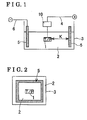
- Fig. 1 is a cross-sectional view schematically illustrating a manner of electrolytic oxidation for forming an electrolytic oxidation ceramic coating according to a first embodiment
- Fig. 2 is a front view schematically illustrating the manner of electrolytic oxidation for forming the electrolytic oxidation ceramic coating according to the first embodiment
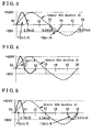
- Fig. 3 is a waveform diagram illustrating waveforms of voltage applied between a test piece and a mating pole in the electrolytic oxidation according to the first embodiment
- Fig. 4 is a waveform diagram illustrating the waveforms of the voltage applied between the test piece and the mating pole in the electrolytic oxidation according to a third embodiment
- Fig. 5 is a waveform diagram illustrating the waveforms of the voltage applied between the test piece and the mating pole in the electrolytic oxidation according to a fourth embodiment
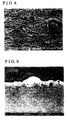
- Fig. 6 is a diagram illustrating a surface of the electrolytic oxidation ceramic coating formed in the electrolytic oxidation according to the first embodiment
- Fig. 7 is a diagram illustrating a cross-section of the electrolytic oxidation ceramic coating formed in the electrolytic oxidation according to the first embodiment
- Fig. 8 is a diagram illustrating a surface of the electrolytic oxidation ceramic coating formed in the electrolytic oxidation according to a first comparative example
- Fig. 9 is a diagram illustrating a cross-section of the electrolytic oxidation ceramic coating formed in the electrolytic oxidation according to the first comparative example
- Fig. 10 is a schematic diagram illustrating the cross-section of the electrolytic oxidation ceramic coating formed in the electrolytic oxidation according to the first embodiment
- Fig. 11 is a schematic diagram illustrating the cross-section of the electrolytic oxidation ceramic coating formed in the electrolytic oxidation according to the first comparative example
- Fig. 12 is a perspective view illustrating a manner of a sliding test
- Fig. 13 is a diagram illustrating results of the sliding test
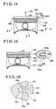
- Fig. 14 is a side view schematically illustrating a state in which the electrolytic oxidation ceramic coating is formed on surfaces of a piston ring groove;
- Fig. 15 is a side view illustrating the piston in which the electrolytic oxidation ceramic coating is formed on the surfaces of a piston ring groove;
- Fig. 16 is a side view illustrating schematically illustrating a state in which the electrolytic oxidation ceramic coating is formed on surfaces of a piston ring groove.
- a test piece (main body) 1 having an aluminum alloy as a base material, and a container 3 containing an alkali electrolyte (electrolyte) 2 are prepared.
- the test piece 1 is formed in a manner where a heat treatment (T6 treatment) is applied to an aluminum alloy casting.
- a size of the test piece 1 is 15.75 millimeter by 6.35 millimeter by 10.16 millimeter.
- the aluminum alloy labeled as JIS-AC8A an aluminum alloy casting, an alloy of aluminum, silicon, copper and magnesium
- the aluminum alloy includes 12% of silicon, 1% of copper and 1% of magnesium, in mass ratio.
- the alkali electrolyte 2 is provided in a manner where a phosphor compound, a zirconium compound and a titanium compound are dissolved in water.
- the phosphor compound is a sodium pyrophosphate (Na 4 P 2 O 7 ⁇ 10H 2 O).
- the phosphor compound contributes toward smoothing roughness of a surface of an electrolytic oxidation ceramic coating and toward stabilizing the electrolyte.
- the zirconium compound is a potassium zirconium carbonate (K 2 [Zr (OH) 2 (CO 3 ) 2 ]). The zirconium compound becomes a component of the electrolytic oxidation ceramic coating.
- the titanium compound is potassium titanium oxalate (K 2 [TiO(C 2 O 4 ) 2 ]-2H 2 O).
- the titanium compound serves as catalyst during a coating formation.
- the phosphor compound, the zirconium compound and the titanium compound are soluble in water.
- a concentration of the sodium pyrophosphate is 25.92g/L
- a concentration of the potassium zirconium carbonate is 8.51g/L
- a concentration of the potassium titanium oxalate is 10.27g/L.
- the rectangular-solid-shaped test piece (main body) 1, serving as an electrode, is immersed in the alkali electrolyte 2 (cubic capacity: approximately 20 liters), contained in the container 3 via a first fixing jig 10.
- a square-ring-shaped mating pole 5 is immersed in the alkali electrolyte 2, contained in the container 3.
- the test piece 1 is connected to a terminal of a power source device via a first electrode jig 4.
- the mating pole 5 is connected to another terminal of the power source device via a second electrode jig 6.
- the mating pole 5 is made of stainless steel (SUS304).
- SUS304 stainless steel
- Fig. 2 is a planar view illustrating a state where the coating is being formed in the container 3.
- the mating pole 5 is formed into a square-ring shape, extending annularly around the test piece 1 in a continuous manner.
- an absolute value of a pulse of a positive electric potential is larger than an absolute value of a pulse of a negative electric potential. Therefore, the mating pole 5 is specified to be a negative pole and the test piece 1 is specified to be a positive pole.
- an electrical voltage (alternative current voltage) is applied between the test piece 1 and mating pole 5 from the power source device.
- the coating formation is conducted while electricity is discharged (glow discharge or arc discharge). Both of or one of the glow discharge and the arc discharge may occur.
- a target thickness of the electrolytic oxidation ceramic coating is specified to be 5.0 ⁇ m.
- An average distance K (see Fig. 1 ) between a portion of the test piece 1 where the coating is formed and the mating pole 5 is specified to be 2.5 centimeters.
- a temperature of the electrolytic oxidation ceramic coating is cooled to 5 C° or less by means of a heat exchanger so as to restrict a generation of roughness of the surface of the electrolytic oxidation ceramic coating.
- a temperature of the test piece 1 is left to nature.
- the speed of coating formation is specified to be 3.1 to 3.2 ⁇ m/min.
- a characteristic line A shown in Fig. 3 illustrates a sine waveform of the general alternative current voltage in 60 Hz.
- One period (16.67 millisecond) of the alternative current voltage is equally divided into six parts so as to specify time t0, time t1, time t2, time t3, time t4, time t5 and time t6.
- +Sin1/6 shows a time range where the pulse of the positive electric potential is applied for 1/6 of the period.
- -Sin1/6 shows a time range where the pulse of the negative electric potential is applied for 1/6 of the period.
- the pulse of the positive electric potential is applied from time to (energization starting time) to time t1 (2.78 milliseconds) so that a maximum voltage becomes +424 volt.
- the pulse of the positive electric potential stimulates elution from the base material, made of the aluminum alloy so as to form the electrolytic oxidation ceramic coating.
- the voltage is not applied from time t1 (2.78 milliseconds) to time t3 (8.34 milliseconds) (i.e., non-energization time).
- the pulse of the negative electric potential is applied from time t3 (8.34 milliseconds) to time t4 (11.12 milliseconds) so that a maximum voltage becomes -85 volt.
- the pulse of the negative electric potential stimulates elution of the base material and elution of the formed electrolytic oxidation ceramic coating. Then, voltage is not applied from time t4 (11.12 millisecond) to time t6 (16.67 milliseconds) (i.e., non-energization time). Thus the periodical alternative current voltage is repetitively applied. As described above, the alternative current voltage is applied between the test piece 1 and the mating pole 5, so that the electrolytic oxidation ceramic coating is formed on a surface of the test piece 1.
- the coating formation time is specified to be 90 seconds.
- time t1 When a time frame from the time point when the application of the pulse of the positive electric potential is finished (time t1) to the time point when the application of the pulse of the negative electric potential starts (time t3) is specified to be relatively long, the roughness of the surface of the electrolytic oxidation ceramic coating is restricted but the electrolytic oxidation ceramic coating is formed relatively slow.
- time t3 when a time frame from the time point when the application of the pulse of the positive electric potential is finished (time t1) to the time point when the application of the pulse of the negative electric potential starts (time t3) is specified to be relatively short, the electrolytic oxidation ceramic coating is formed quicker but the roughness of the surface of the electrolytic oxidation ceramic coating increases.
- the electrolytic oxidation ceramic coating is formed relatively slow.
- the absolute value of the negative electrolytic oxidation ceramic coating is specified to be relatively large, the electrolytic oxidation ceramic coating is formed relatively quickly.
- the absolute value of the negative electric potential is excessively large, the test piece (the main body) 1 suddenly develops heat, and the roughness of the surface of the electrolytic oxidation ceramic coating increases.
- the electrolytic oxidation ceramic coating is formed relatively quickly but the roughness of the surface of the electrolytic oxidation ceramic coating increases.
- the electrolytic oxidation ceramic coating is formed relatively slow.
- the electrolytic oxidation ceramic coating is formed relatively slow, and the roughness of the surface of the electrolytic oxidation ceramic coating increases.
- the electrolytic oxidation ceramic coating is formed relatively quickly and the roughness of the surface of the electrolytic oxidation ceramic coating decreases. Therefore, a level of smoothness is improved.
- Figs. 6 and 7 each illustrate an example of a configuration of the electrolytic oxidation ceramic coating according to the first embodiment.
- Fig. 6 illustrates an example of the surface of the electrolytic oxidation ceramic coating (magnification ratio: 1000-fold).
- Fig. 7 illustrates an example of the cross-section of the electrolytic oxidation ceramic coating (magnification ratio: 3000-fold).
- Fig. 10 schematically illustrates the cross-section of the electrolytic oxidation ceramic coating according to the first embodiment.
- the electrolytic oxidation ceramic coating includes an inner layer, an outer layer and an intermediate layer.
- the inner layer is rich in aluminum oxide (Al 2 O 3 , shown in light gray in Fig. 7 ) coated on the surface of the main body (test piece 1) having the aluminum alloy as the base material.
- the outer layer forming a most outer layer of the electrolytic oxidation ceramic coating, is rich in zirconium oxide (ZrO 2 ) and titanium oxide (TiO 2 ).
- the intermediate layer positioned between the inner and outer layers, includes an aluminum oxide (Al 2 O 3 ), a zirconium oxide (ZrO 2 ) and a titanium oxide (TiO 2 ).
- Al 2 O 3 aluminum oxide
- ZrO 2 zirconium oxide
- TiO 2 titanium oxide
- the inner layer serving as the aluminum oxide layer is formed on the surface of the main body (test piece 1) having the aluminum alloy as the base material.
- the inner layer is rich in aluminum oxide (Al 2 O 3 ).
- the inner layer may also include at least one of the zirconium oxide (ZrO 2 ) and the titanium oxide (TiO 2 ).
- the outer layer is rich in zirconium oxide (ZrO 2 ) and titanium oxide (TiO 2 ).
- the outer layer may also include the aluminum oxide (Al 2 O 3 ).
- a ratio of ⁇ - Al 2 O 3 . existing in the aluminum oxide is relatively low, and a ratio of ⁇ - Al 2 O 3 existing in the aluminum oxide is higher than ⁇ - Al 2 O 3 existing in the electrolytic oxidation ceramic coating.
- hardness of ⁇ - Al 2 O 3 is lower than that of ⁇ - Al 2 O 3
- toughness of ⁇ - Al 2 O 3 is higher than that of ⁇ - Al 2 O 3 . Therefore, hardness of the electrolytic oxidation ceramic coating according to the first embodiment is lower than an electrolytic oxidation ceramic coating formed in a known electrolytic oxidation method.
- the electrolytic oxidation ceramic coating may include a titanium component.
- the generation of a large projection on a surface of the zirconium oxide is restricted.
- the large surface projection does not exist on the electrolytic oxidation ceramic coating.
- the hardness of the electrolytic oxidation ceramic coating is within a range from HV 500 to HV 550, more specifically, within a range from HV 515 to HV 535.
- a first comparative example is carried on under the similar condition to the first embodiment, in which an electrolytic oxidation ceramic coating (target thickness: 5 micrometers as in the first embodiment) is formed on the test piece 1.
- an electrolytic oxidation more specifically, a plasma electrolytic oxidation is executed under the similar condition to the first embodiment.
- an alkali electrolyte is used, which includes a phosphor compound and a zirconium compound as in the first embodiment, but which does not include a titanium compound.
- Figs. 8 and 9 each illustrate a configuration of the electrolytic oxidation ceramic coating observed by the scanning electron microscope (SEM) according to the first comparative example.
- Fig. 8 illustrates a surface of the electrolytic oxidation ceramic coating (magnification ratio: 1000-fold).
- Fig. 9 illustrates a cross-section of the electrolytic oxidation ceramic coating (magnification ratio: 3000-fold).
- Fig. 11 schematically illustrates the cross-section of the electrolytic oxidation ceramic coating more clearly.
- the electrolytic oxidation ceramic coating according to the first comparative example includes an aluminum oxide layer, a zirconium oxide layer and an intermediate layer.
- the aluminum oxide layer is rich in aluminum oxide (Al 2 O 3 , shown in light gray in Figs.
- the zirconium oxide layer forming the most outer layer of the electrolytic oxidation ceramic coating, is rich in zirconium oxide (ZrO 2 , shown in white in Figs. 8 and 9 ).
- the intermediate layer positioned between the aluminum oxide layer and the zirconium oxide layer, includes the aluminum oxide (Al 2 O 3 ) and the zirconium oxide (ZrO 2 ).
- the surface of the test piece 1 is rich in aluminum oxide because aluminum is supplied from the surface of the test piece 1.
- the most outer layer of the electrolytic oxidation ceramic coating is rich in zirconium oxide because zirconium is included in the electrolyte 2 and is supplied therefrom.
- the aluminum oxide is rich in the vicinity of the surface of the test piece 1 (the main body), and the zirconium oxide is rich in the vicinity of the most outer surface of the electrolytic oxidation ceramic coating.
- the electrolytic oxidation ceramic coating according to each of the first embodiment and the first comparative example is configured so that the inner layer thereof close to the surface of the test piece 1 is richer in aluminum oxide than the most outer surface of the electrolytic oxidation ceramic coating and so that the outer layer thereof close to the most outer surface of the electrolytic oxidation ceramic coating is richer in zirconium oxide than the inner layer thereof close to the surface of the test piece 1 (the main body).
- a base of the main body that has the aluminum alloy as the base material includes silicon particles.
- a large surface projection (ZrO 2 , shown in white in Fig. 9 ) exists at a portion where the silicon protrudes from the surface of the aluminum base material.
- the surface roughness of the electrolytic oxidation ceramic coating according to the first comparative example, on which the surface projection is generated, is about Ra 0.85 ⁇ m. The smoothness of the electrolytic oxidation ceramic coating may not be satisfactory.
- a plurality of pinhole-shaped pores is formed dispersedly on the electrolytic oxidation ceramic coating according to the first embodiment.
- the number of pores i.e.
- openings on the surface of the electrolytic oxidation ceramic coating whose diameter is 5 ⁇ m or less, is about 200 to 400.
- Such pores of appropriate size restrict the roughness of the surface of the electrolytic oxidation ceramic coating, and include a function of retaining a lubricant, such as lubricating oil, on the surface of the electrolytic oxidation ceramic coating.
- a mechanism of formation of pores is not necessarily clear, it is presumed that gas emission causes the generation of the pores on the surface of the electrolytic oxidation ceramic coating
- a sliding test (see Fig. 12 ) is executed on the above-described test piece 1.
- a mating member is formed into a substantially ring shape.
- the mating member is made of iron or alloy including iron (material equivalent to a piston ring, i.e., SWOSC-V).
- the mating member is hardened in high-frequency, and therefore the mating member includes a hardening structure. Roughness of the mating member is specified to be Rzjis 2.44 ⁇ m.
- the mating member is made of iron or alloy including iron (SWOSC-V), but the mating member may not be limited to be made of iron series (SWOSC-V), and may be made of SWO-A, SWO-B, SWO-V, SWOSC-B, SWOSM-A, SWOSM-B, SWOSM-C, SWOCV-V, SUP6, SUP7, SUP9, SUP10, SUP11A, SUP12, S55C, S45C and the like, depending on an actual usage condition.
- conditions of the above-described sliding test are that a bottom portion of the ring-shaped mating member is immersed in the lubricating oil to an oil immersion level, the mating member is rotated around an axis thereof, the test piece 1 is thrust to an outer circumferential surface of the mating member by a predetermined level of load, and the mating member slides relative to the electrolytic oxidation ceramic coating of the test piece 1 in one direction.
- the load is specified to be 588N
- an average sliding speed is specified to be 0.3 m/second
- a rotational speed is specified to be 50 rpm to 250 rpm
- an engine oil (5w-30) is used as the lubricating oil
- a temperature of the lubricating oil is left to nature
- a sliding time is specified to be 30 minutes.
- an appearance of the surface of the electrolytic oxidation ceramic coating formed on the test piece 1 is observed before and after the sliding test with a naked eye as well as by the scanning electron microscope (SEM), and a comparative abrasion amount is calculated.
- an anodic oxide coating (a hard anodic oxide coating) is formed in a known anodization.
- Conditions of the anodizaion is that a direct current is applied in a sulfuric acid aqueous solution, an electric voltage is specified to be 40 volt, a current density is specified to be 2 ampere/dm 2 , a constant current is applied, and the speed of coating formation is specified to be 1 micrometer/minute.
- the sliding test is also executed in the first and second comparative examples.
- Fig. 13 illustrates results of the sliding test. As illustrated in Fig.
- both of the comparative abrasion amount of the test piece 1 (the electrolytic oxidation ceramic coating) and the comparative abrasion amount of the mating member are small in the first embodiment.
- the comparative abrasion amount of the test piece 1 and the comparative abrasion amount of the mating member are small because abrasion resistance of the test piece 1 is improved while aggressiveness of the test piece 1 to the mating member is relatively low in the first embodiment.
- the hardness of the test piece 1 (the electrolytic oxidation ceramic coating) is relatively high (HV 800 or more) and the aggressiveness of the test piece 1 to the mating member is also relatively high.
- the hardness of the electrolytic oxidation ceramic coating is relatively high, a self-abrasion amount of the electrolytic oxidation ceramic coating is also relatively large because of the surface projection generated on the surface of the electrolytic oxidation ceramic coating.
- the hardness of the anodic oxide coating is about HV 400, and the comparative abrasion amount of the test piece 1 is relatively large.
- the comparative abrasion amount of the mating member is also large because of abrasion powder.
- Second to fourth embodiments are further executed.
- the alternative current voltage is applied between the test piece 1 and the mating pole 5 so as to form an electrolytic oxidation ceramic coating under the similar conditions to the first embodiment.
- waveforms of the alternative current voltage, which is applied between the test piece 1 and the mating pole 5, are modified. More specifically, according to the third embodiment, as waveforms (duty ratio: 2/6 ⁇ 0.33) are illustrated in Fig. 4 , the pulse of the positive electric potential is applied from time t0 (energization starting time) to time t1 (2.78 milliseconds) so that the maximum voltage becomes +424 volt.
- the pulse of the negative electric potential is applied from time t1 (2.78 milliseconds) to time t2 (5.56 milliseconds) so that the maximum voltage becomes -85 volt.
- the voltage is not applied from time t2 (5.56 millisecond) to time t6 (16.67 milliseconds) (i.e., non-energization time).
- the periodical alternative current voltage is repetitively applied.
- the pulse of the positive electric potential is applied from time t0 (energization starting time) to time t1 (2.78 milliseconds) so that the maximum voltage becomes +424 volt. Subsequently, the voltage is not applied from time t1 (2.78 millisecond) to time t5 (13.90 milliseconds) (i.e., non-energization time). Subsequently, the pulse of the negative electric potential is applied from time t5 (13.90 milliseconds) to time t6 (16.67 milliseconds) so that the maximum voltage becomes -85 volt. Thus, the periodical alternative current voltage is repetitively applied.
- the following table 1 illustrates results of the test according to the second to forth embodiments.
- the roughness of the surface of the electrolytic oxidation ceramic coating, the thickness of the electrolytic oxidation ceramic coating, the speed of coating formation, the hardness of the electrolytic oxidation ceramic coating are suitable.
- Vickers hardness is measured, using a load of 5g. Accordingly, generation of the surface projections, which may cause abrasion, is restricted in each of the second to fourth embodiments.
- the smoothness of the electrolytic oxidation ceramic coating is improved, the self-abrasion amount of the electrolytic oxidation ceramic coating (the test piece 1) is reduced while the aggressiveness to the mating member is decreased.
- the hardness of the electrolytic oxidation ceramic coating is HV 500 to HV 600, which is an appropriate level of the hardness, the aggressiveness to the mating member is further decreased.
- a time frame between the time point when the application of the pulse of the positive electric potential finishes (time t1) to the time point when the application of the pulse of the negative electric potential starts (time t5) is relatively long. In such a case, the roughness of the surface of the electrolytic oxidation ceramic coating is restricted, but the speed of coating formation (1.72 ⁇ m/minute) is relatively slow.
- a time frame between the time point when the application of the pulse of the positive electric potential finishes (time t1) to the time point when the application of the pulse of the negative electric potential starts (time t2) is relatively short. In such a case, the speed of coating formation (3.56 ⁇ m/minute) is relatively quick, but the roughness of the surface of the electrolytic oxidation ceramic coating increases (0.612 ⁇ m).
- the speed of coating formation of the electrolytic oxidation ceramic coating is relatively quick but the roughness of the electrolytic oxidation ceramic coating increases in a case where the distance between the test piece 1 and the mating pole 5 is relatively short, compared to a case where the distance between the test piece 1 and the mating pole 5 is relatively long.
- Figs. 14 and 15 correspond to the fifth embodiment. Configuration of the fifth embodiment is similar to the first embodiment.
- a piston 100 (a member including a recessed portion and serving as a piston body and the main body) is applied.
- First, second and third piston ring grooves 102, 103 and 104 are formed at the piston 100.
- the first to third piston ring grooves 102, 103, and 104 serve as a plurality of ring grooves, which are applied to an internal combustion engine of a vehicle, such as an automobile, and the like.
- the piston 100 is made of the aluminum alloy.
- the aluminum alloy is made of a casted part (a die casted part, a sand casted part) or a sintered part, each of which includes 10% to 30% of silicon in mass ratio.
- the piston 100 is formed in a manner where a cutting process is executed on the casted part or the sintered part. Further, the piston 100 may be formed in a manner where the cutting process is executed on a forged part, or a compacted part, in which rapidly solidified powder is consolidated.
- a covering layer of silicon rubber and the like is arranged at a portion of the piston 100 other than the first piston ring 102, which is closest to a head surface 101 among the first to third piston ring grooves 102,103 and 104.
- a distance KA between the mating pole 500 and an outer circumferential surface of the piston 100 in the vicinity of the first piston ring groove 102 is specified to be 0.5 to 50 millimeters, or more specifically, 10 to 20 millimeters.
- the electrolytic oxidation is executed under the similar condition to the first embodiment, in which the alternative current voltage, showing the pulse of the positive electric potential and the pulse of the negative electric potential, is applied between the piston 100 and the mating pole 500 via a first power supplying portion 120 and a second power supplying portion 520 for 30 to 600 seconds. Consequently, an electrolytic oxidation ceramic coating 200, whose thickness is 2 to 20 ⁇ m, or more specifically, 3 to 10 ⁇ m, is formed. More specifically, as illustrated in Fig. 15 , the electrolytic oxidation ceramic coating 200 is formed on groove side surfaces 102a, which face each other, and on a groove bottom surface 102c. Subsequently, the covering layer for masking is removed from the piston 100.
- the electrolytic oxidation ceramic coating 200 is not limited to be formed on the first piston ring groove 102, but may be formed on the second and third piston ring grooves 103 and 104.
- a ring-shaped mating pole 530 shown in Fig. 16 may be applied.
- the mating pole 530 includes an insertion portion 531 and a facing portion 532. The insertion portion 531 may be inserted into a spaced portion of the first piston ring groove 102, the spaced portion being surrounded by the groove side surfaces 102a and the groove bottom surface 102c.
- the facing portion 532 faces the outer circumferential surface of the piston 100 so as to be distant therefrom.
- the electrolytic oxidation ceramic coating may be formed on wall surfaces of the first piston ring groove 102 in a manner where the insertion portion 531 of the mating pole 530 is inserted into the spaced portion of the first piston ring groove 102, and energization is executed between the mating pole 530 and the piston 100. Because the insertion portion 531 of the mating pole 530 is inserted into the first piston ring groove 102, the insertion portion 531 of the mating pole 530 is positioned close to the groove side surfaces 102a and the groove bottom surface 102c of the first piston ring groove 102.
- the electrolytic oxidation ceramic coating is formed on the piston 100, whose base material is the aluminum alloy and which is mounted on the internal combustion engine.
- the electrolytic oxidation ceramic coating may be formed on a piston, whose base material is aluminum alloy and which is mounted on an external combustion engine.
- the electrolytic oxidation ceramic coating may be formed on an inner wall surface of a cylinder bore of a cylinder block, whose base material is the aluminum alloy and which is mounted on either the internal combustion engine or the external combustion engine.
- the electrolytic oxidation ceramic coating may be formed on an inner circumferential wall surface of a cylinder, whose base material is the aluminum alloy and which is mounted on a brake device.
- the electrolytic oxidation ceramic coating may be formed on an outer circumferential wall surface of a spool valve, whose base material is the aluminum alloy.
- the electrolytic oxidation ceramic coating may be formed on an inner circumferential wall surface of a spool hole for sliding the spool valve, whose base material is the aluminum alloy.
- one period of frequency of the alternative current voltage is divided into six parts, and the pulse of the positive electric potential is applied for 1/6 period while the pulse of the negative electric potential is applied for 1/6 period.
- one period of the alternative current voltage may be divided into four parts, and the pulse of the positive electric potential may be applied for 1/4 period while the pulse of the negative electric potential is applied for 1/4 period.
- one period of the alternative current voltage may be divided into eight parts, and the pulse of the positive electric potential may be applied for 1/8 period while the pulse of the negative electric potential is applied for 1/8 period.
- time length for applying the pulse of the positive electric potential and time length for applying the pulse of the negative electric potential are substantially the same. However, the time length for applying the pulse of the negative electric potential may be shorter than the time length for applying the pulse of the positive electric potential.
- the electrolytic oxidation ceramic coating is not limited to the configuration shown in Fig. 10 , and may include an inner layer, which is rich in aluminum oxide (Al 2 O 3 ) coated on the surface of the main body (test piece 1) having the aluminum alloy as the base material, an outer layer, which forms a most outer layer of the electrolytic oxidation ceramic coating and is rich in titanium oxide (TiO 2 ), and an intermediate layer, which is positioned between the inner and outer layers, and includes the aluminum oxide (Al 2 O 3 ) and the titanium oxide (TiO 2 ).
- an inner layer which is rich in aluminum oxide (Al 2 O 3 ) coated on the surface of the main body (test piece 1) having the aluminum alloy as the base material
- an outer layer which forms a most outer layer of the electrolytic oxidation ceramic coating and is rich in titanium oxide (TiO 2 )
- an intermediate layer which is positioned between the inner and outer layers, and includes the aluminum oxide (Al 2 O 3 ) and the titanium oxide (TiO 2 ).
- An aluminum alloy member including a main body having an aluminum alloy serving as a base material and an electrolytic oxidation ceramic coating coated at a portion of a surface of the main body and including a most outer layer and an Inner layer which is arranged close to the main body relative to the most outer layer, the inner layer in which an aluminum oxide is richer than the most outer layer, the most outer layer in which at least one of a zirconium oxide and a titanium oxide is richer than the inner surface, wherein a surface projection is prevented from generating on the electrolytic oxidation ceramic coating and a surface roughness Ra thereof is specified to be equal to or smaller than 0.7 ⁇ m
- An aluminum alloy member including a main body having an aluminum alloy serving as a base material and an electrolytic oxidation ceramic coating coated at a portion of a surface of the main body and including a most outer layer and an inner layer which is arranged close to the main body relative to the most outer layer, the inner layer in which an aluminum oxide is richer than the most outer layer, the most outer layer in which at least one of a zirconium oxide and a titanium oxide is richer than the inner surface.
- the present embodiment is applicable to an aluminum alloy member used for a component for a vehicle, an industrial instrument, and the like and a method for manufacturing the same.
- the meaning of "the aluminum oxide is rich” is that a dimensional ratio of the aluminum oxide is greater than a dimensional ratio of a volume of the titanium oxide or a total volume of the titanium oxide and the zirconium oxide.
- the meaning of "the volume of the titanium oxide or the total volume of the titanium oxide and the zirconium oxide is rich” is that a dimensional ratio of the titanium oxide or a dimensional ratio of the total of the titanium oxide and the zirconium oxide is greater than a dimensional ratio of the aluminum oxide.
- the dimensional ratio is greater when a component in a thickness direction of a cross section of the electrolytic oxidation ceramic coating is analyzed by an electron probe micro-analyzer (EPMA), an energy dispersive X-ray fluorescence (EDX), an X-ray fluorescence, and the like. Accordingly, in a case where the electrolytic oxidation ceramic coating is analyzed by the aforementioned method, the dimensional ratio of the aluminum oxide in the electrolytic oxidation ceramic coating is larger at an inner surface (i.e., an inner layer) close to the main body than that at a most outer surface (i.e., a most outer layer) of the electrolytic oxidation ceramic coating.
- the dimensional ratio of the volume of the titanium oxide or the total volume of the titanium oxide and the zirconium oxide is greater at the most outer layer than that at the inner layer.
- the dimensional ratio of the aluminum oxide and the dimensional ratio of the total of the zirconium oxide and the titanium oxide may continuously vary In the thickness direction of the electrolytic oxidation ceramic coating or may discontinuously vary in the thickness direction of the electrolytic oxidation ceramic coating.
- the zirconium oxide enhances toughness of the entire electrolytic oxidation ceramic coating, prevents an excessive increase of the hardness of the electrolytic oxidation ceramic coating, and improves a corrosion resistance.
- the titanium oxide functions in the same way as the zirconium oxide.
- the surface roughness Ra of the electrolytic oxidation ceramic coating is specified to be equal to or smaller than 0.7 ⁇ m.
- the lower limit of the surface roughness Ra of the electrolytic oxidation ceramic coating is 0.1 ⁇ m, 0.2 ⁇ m, or 0.3 ⁇ m, for example.
- the generation of the surface projection is restrained, which leads to an enhancement of flatness of the electrolytic oxidation ceramic coating.
- the titanium compound or titanium included in the electrolyte functions as a catalyst upon electrolytic oxidation to thereby accelerate a generation of the aluminum oxide, the zirconium oxide, and the titanium oxide included in the electrolytic oxidation ceramic coating.
- the generation of the surface projection is prevented accordingly.
- the surface roughness of the electrolytic oxidation ceramic coating is reduced.
- the aluminum oxide and the zirconium oxide may be either crystalline or amorphous and may include a titanium compound (oxide).
- the average hardness of the electrolytic oxidation ceramic coating is equal to or smaller than HV 600.
- the electrolytic oxidation ceramic coating is desirably harder than the base material constituting the main body.
- the average hardness of the electrolytic oxidation ceramic coating is in a range from HV 400 to HV 600.
- toughness of the electrolytic oxidation ceramic coating is ensured and the aggressiveness to the mating member decreases.
- the lower limit of the average hardness of the electrolytic oxidation ceramic coating is HV 400, HV 425, or HV 450, for example.
- the upper limit of the average hardness of the electrolytic oxidation ceramic coating is HV 600, HV 575, or HV 550, for example.
- a sliding member serves as the main body, for example.
- the aluminum alloy constituting the base material of the main body may be a casted part, a forged part, or a sintered part.
- the sintered part is obtained by a sinter of a consolidation compact achieved by a consolidation of alloy powder such as rapidly solidified powder.
- An alloy of aluminum and silicon, an alloy of aluminum, silicon, and magnesium, an alloy of aluminum, silicon, and copper, and an alloy of aluminum, silicon, copper, and magnesium, all of which include silicon, are applicable to the aluminum alloy, for example.
- unavoidable impurities may be included.
- 10% or less, 15% or less, 20% or less, or 30% or less silicon by weight may be included.
- the aforementioned aluminum alloy may include 10% or less or 15% or less copper.
- the aforementioned aluminum alloy may include 5% or less or 10% or less magnesium. According to the aforementioned embodiments, even when the silicon is included in the base material, the generation of the surface projection is restrained during a forming of the coating and the surface roughness of the electrolytic oxidation ceramic coating is reduced, which is an advantage for forming the electrolytic oxidation ceramic coating at the aluminum alloy that includes the silicon.
- the generation of the surface projection from which the abrasion tends to originate is desirably restrained and the surface roughness Ra is desirably specified to be equal to or smaller than 0.7 ⁇ m. Because the generation of the surface projection from which the abrasion tends to originate is restrained, the self-abrasion amount of the electrolytic oxidation ceramic coating is reduced and the aggressiveness to the mating member is restrained. Further, because the hardness of the electrolytic oxidation ceramic coating is not excessive and is appropriate, the aggressiveness to the mating member is further reduced.
- the surface roughness Ra of the electrolytic oxidation ceramic coating is specified to be 0.6 ⁇ m or less, 0.5 ⁇ m or less, 0.4 ⁇ m or less, or 0.3 ⁇ m or less, for example.
- the aforementioned electrolyte desirably includes the zirconium compound and the titanium compound.
- the aforementioned electrolyte desirably includes the titanium compound.
- the zirconium compound may desirably be soluble.
- the soluble zirconium compound is advantageous for densification of the electrolytic oxidation ceramic coating.
- Organic acid zirconium salt such as zirconium acetate, zirconium formate, and zirconium lactate is applicable to the zirconium compound.
- zirconium complex salt such as potassium zirconium carbonate, ammonium zirconium carbonate, ammonium zirconium acetate, and sodium zirconium oxalate is applicable to the zirconium compound. More specifically, potassium zirconium carbonate (K 2 [Zr(OH) 2 (CO 3 ) 2 ] is used as the zirconium compound.
- a density of the zirconium compound in the electrolyte is 2g to 35g or 6g to 10g per litter, for example.
- At least one of oxalate, carbonate, and silicate is applicable to the titanium compound. More specifically, potassium titanium oxalate (K 2 [TiO(C 2 O 4 ) 2 ]) is used as the titanium compound.
- the titanium compound or the titanium functions as a catalyst upon forming of the coating and is effective for enhancement of an oxide generation.
- the further densification of the electrolytic oxidation ceramic coating is achieved, thereby improving the surface roughness of the electrolytic oxidation ceramic coating and accelerating the formation speed of the coating.
- a phosphorous compound is desirably included in the electrolyte.
- the soluble phosphorous compound is desirable.
- the phosphorous compound accelerates a generation of the aluminum oxide and contributes to a flatness of the surface of the electrolytic oxidation ceramic coating and stabilization of the electrolyte.
- Phosphate, polyphosphate, organic phosphonate, tartrate, citrate, and aminocarboxylate are applicable to the phosphorous compound. More specifically, at least one of sodium pyrophosphate (Na 4 P 2 O 7 ⁇ 10H 2 O) and the like is used as the phosphorous compound, for example.
- a density of the soluble phosphorous compound in the electrolyte is 10g to 100g or 20g to 30g per litter, for example.
- the phosphor compound, zirconium compound and the titanium compound, included in the electrolyte are described in the atomic number ratio as follows.
- the temperature of the electrolyte is not limited. However, the temperature of the electrolyte is generally specified to be 60 °C or less, 40 °C or less, or more specifically, 10 °C or less. The electrolyte may be cooled if necessary.
- the electricity When the voltage is applied between the main body and the mating pole, the electricity may be discharged (glow discharge or arc discharge). While the electricity is being discharged, a portion of the surface layer of the main body is melted and coagulated.
- the electrolytic oxidation ceramic coating whose main components are the aluminum oxide, the zirconium oxide and the titanium oxide, is formed while obtaining oxygen generated at a positive pole.
- Either the alternative current voltage or the direct current voltage may be applied between the main body and the mating pole. However, when only the positive electric potential of the direct current voltage is applied, the roughness of the electrolytic oxidation ceramic coating may increase.
- the alternative current voltage may be applied so as to improve the smoothness of the electrolytic oxidation ceramic coating.
- the non-energization time may be provided between the pulse of the positive electric potential and the pulse of the negative electric potential, so that the generation of the electrolytic oxidation ceramic coating is temporality stopped and the electrolytic oxidation ceramic coating is cooled.
- heat is developed at the coating formed portion of the main body.
- a sine wave, a square wave or a triangle wave is applied, for example.
- the frequency of the alternative current voltage may be appropriately specified as long as the alternative current voltage includes the pulse of the positive and negative electric potential.
- the frequency of the alternative current voltage includes 5 to 1500 Hz, 10 to 1000Hz, 20 to 100Hz, or 45 to 65Hz.
- the non-energization time may be provided between the pulse of the positive electric potential and the pulse of the negative electric potential, which configure the alternative current voltage.
- the positive electric potential may be specified within a range of 50 to 600 volts or 80 to 500 volts, for example.
- the negative electric potential may be specified within a range of -10 to -400 volts or -20 to -300 volts, for example.
- the duty ratio of the applying voltage may be within a range of 0.1 to 0.8, 0.2 to 0.7 or 0.2 to 0.5. According to such duty ratio, the appropriate voltage application time and the appropriate non-energization time may be obtained. Therefore, the electrolytic oxidation ceramic coating is suitably formed.
- the "voltage application time” mentioned herein includes the time when the pulse of the positive and negative electric potential is applied.
- a maximum level of applying voltage is specified to be 430 volts or less.
- the voltage is raised to the maximum voltage level within 1 to 10 milliseconds (more specifically, 1 to 3 milliseconds).
- An energization interval (non-energization time) between the pulse of the positive electric potential and the pulse of the negative electric potential is specified to be 1 to 15 milliseconds (more specifically, 5 to 8 milliseconds).
- the absolute value of the negative electric potential may be specified to be 2/3 to 1/10 (more specifically, 1/6 to 1/4) of the absolute value of the positive electric potential.
- Continuous frequency may be specified to be 10 to 200Hz (more specifically, 50 to 60Hz). Accordingly, power of the pulse of the positive electric potential may not become too high.
- the smoothness of the electrolytic oxidation ceramic coating (zirconium oxide) is improved.
- the non-energization time between the pulse of the positive electric potential and the negative electric potential is shortened so as to maintain activeness of the surface of the electrolytic oxidation ceramic coating and restrict decrease in formation speed of coating.
- Pulse-type direct voltage may be applied between the main body and the mating member 5.
- the "pulse-type direct voltage” mentioned herein refers to the fact that the energization time (ON time), in which the positive voltage is applied between the main body and the mating member, and the non-energization time (OFF time), in which the positive voltage is not applied between the main body and the mating member, are alternately specified.
- the distance between the coating formed portion of the main body and the mating member at the time of coating formation may be appropriately specified on the basis of the voltage applied between the main body and the mating member, a discharge performance between the main body and the mating member, a composition of the electrolyte, and a concentration of the electrolyte.
- the electric current may easily flow between the main body and the mating member, a large amount of discharge may easily occur, and accordingly the roughness of the surface of the electrolytic oxidation ceramic coating may easily increase.
- the average distance between the main body and the mating member 5 when the average distance between the main body and the mating member 5 is relatively long, a small amount of discharge may occur between the main body and the mating member 5, discharge may weaken on a surface of a recessed portion and the like, and accordingly, the coating formation performance may be deteriorated. Further, the formation speed of the electrolytic oxidation ceramic coating may decrease and productivity may be reduced. Accordingly, the average distance between the coating formed portion of the main body and the mating member may suitably be specified to be 0.05 to 10 centimeters, or more specifically, 1 to 10 centimeters.
- the average distance between the coating formed portion of the main body and the mating member may be specified to be 1.3 to 6 centimeters in a case where the applying positive electric potential is specified to be 350 to 430 volts.
- the coating formation time is appropriately specified on the basis of the distance between the coating formed portion of the main body and the mating member, the level of the voltage applied between the main body and the mating member, the concentration of the electrolyte, the composition of the electrolyte, the target thickness of the electrolytic oxidation ceramic coating and the size of the main body.
- the coating formation time may be specified to be about 10 seconds to 30 minutes, 20 seconds to 10 minutes, 30 seconds to 3 minutes, though not limited to the examples mentioned herein.
- the coating formation speed is specified on the basis of the distance between the coating formed portion of the main body and the mating member, the level of the voltage applied between the main body and the mating member, the concentration of the electrolyte, the composition of the electrolyte, the target thickness of the electrolytic oxidation ceramic coating and the size of the main body.
- the coating formation speed may be specified to be about 0.2 to 100 ⁇ m/min, 1 to 50 ⁇ m/min, or more specifically, 1 to 20 ⁇ m/min and 2 to 10 ⁇ m/min, though not limited to the examples mentioned herein.
- An aluminum alloy member includes a main body (1) including an aluminum alloy serving as a base material, and an electrolytic oxidation ceramic coating coated at a portion of a surface of the main body (1) and including a most outer layer and an inner layer which is arranged close to the main body (1) relative to the most outer layer, the inner layer in which an aluminum oxide is richer than the most outer layer, the most outer layer in which a volume of a titanium oxide or a total volume of the titanium oxide and a zirconium oxide is richer than the inner surface.
Landscapes
- Chemical & Material Sciences (AREA)
- Engineering & Computer Science (AREA)
- Chemical Kinetics & Catalysis (AREA)
- Electrochemistry (AREA)
- Materials Engineering (AREA)
- Metallurgy (AREA)
- Organic Chemistry (AREA)
- Inorganic Chemistry (AREA)
- Other Surface Treatments For Metallic Materials (AREA)
Applications Claiming Priority (1)
| Application Number | Priority Date | Filing Date | Title |
|---|---|---|---|
| JP2008202781A JP5394021B2 (ja) | 2008-08-06 | 2008-08-06 | アルミニウム合金ピストン部材およびその製造方法 |
Publications (3)
| Publication Number | Publication Date |
|---|---|
| EP2154268A2 true EP2154268A2 (fr) | 2010-02-17 |
| EP2154268A3 EP2154268A3 (fr) | 2017-03-15 |
| EP2154268B1 EP2154268B1 (fr) | 2020-04-29 |
Family
ID=41328610
Family Applications (1)
| Application Number | Title | Priority Date | Filing Date |
|---|---|---|---|
| EP09167374.9A Active EP2154268B1 (fr) | 2008-08-06 | 2009-08-06 | Élément d'alliage d'aluminium et son procédé de fabrication |
Country Status (3)
| Country | Link |
|---|---|
| US (2) | US20100032301A1 (fr) |
| EP (1) | EP2154268B1 (fr) |
| JP (1) | JP5394021B2 (fr) |
Cited By (1)
| Publication number | Priority date | Publication date | Assignee | Title |
|---|---|---|---|---|
| WO2018202860A1 (fr) * | 2017-05-05 | 2018-11-08 | Federal-Mogul Nürnberg GmbH | Revêtement thermoisolant pour un piston en aluminium |
Families Citing this family (21)
| Publication number | Priority date | Publication date | Assignee | Title |
|---|---|---|---|---|
| US20120245065A1 (en) * | 2009-08-18 | 2012-09-27 | The Lubrizol Corporation | Lubricating Composition Containing an Antiwear Agent |
| US8609254B2 (en) | 2010-05-19 | 2013-12-17 | Sanford Process Corporation | Microcrystalline anodic coatings and related methods therefor |
| US8512872B2 (en) | 2010-05-19 | 2013-08-20 | Dupalectpa-CHN, LLC | Sealed anodic coatings |
| WO2012174386A1 (fr) * | 2011-06-15 | 2012-12-20 | Henkel Ag & Co. Kgaa | Procédé et appareil de réduction d'émissions et/ou de réduction de frottement dans un moteur à combustion interne |
| JP5938374B2 (ja) * | 2012-09-18 | 2016-06-22 | 日立オートモティブシステムズ株式会社 | 内燃機関のピストン |
| JP5681252B1 (ja) * | 2013-08-30 | 2015-03-04 | 株式会社リケン | 内燃機関用ピストンリング |
| JP2015074825A (ja) * | 2013-10-11 | 2015-04-20 | 株式会社栗本鐵工所 | プラズマ電解酸化による皮膜形成方法及び金属材料 |
| DE102013221375A1 (de) * | 2013-10-22 | 2015-04-23 | Ford Global Technologies, Llc | Verfahren zur Herstellung einer beschichteten Bohrungsfläche, insbesondere einer Zylinderbohrung |
| DE102013223011A1 (de) * | 2013-11-12 | 2015-05-13 | Ford-Werke Gmbh | Verfahren zur Herstellung einer beschichteten Oberfläche eines tribologischen Systems |
| JP6220656B2 (ja) * | 2013-12-03 | 2017-10-25 | 富士機械工業株式会社 | 塗工装置 |
| CN107004470A (zh) * | 2014-08-07 | 2017-08-01 | 汉高股份有限及两合公司 | 用于成束电力传输电缆中的电线的电瓷涂层 |
| CN104213171B (zh) * | 2014-09-05 | 2017-02-08 | 山东滨州渤海活塞股份有限公司 | 铝合金活塞表面氧化钛类陶瓷涂层的制备方法 |
| WO2016049191A1 (fr) | 2014-09-23 | 2016-03-31 | General Cable Technologies Corporation | Supports d'électrodéposition pour la formation de revêtements protecteurs déposés électrochimiquement sur des substrats métalliques |
| ES2974638T3 (es) * | 2015-03-19 | 2024-06-28 | Limacorporate Spa | Anclaje glenoideo mejorado para una prótesis de articulación del hombro |
| JP6459865B2 (ja) * | 2015-09-02 | 2019-01-30 | 株式会社デンソー | バルブ装置の製造方法 |
| CN105132990A (zh) * | 2015-09-15 | 2015-12-09 | 湖北轩坤实业有限公司 | Plc控制全自动活塞硬质阳极氧化机 |
| CN108368632B (zh) * | 2015-12-16 | 2020-09-25 | 汉高股份有限及两合公司 | 用于在铝上沉积钛基保护涂层的方法 |
| KR102652258B1 (ko) * | 2016-07-12 | 2024-03-28 | 에이비엠 주식회사 | 금속부품 및 그 제조 방법 및 금속부품을 구비한 공정챔버 |
| US10030314B1 (en) * | 2017-03-27 | 2018-07-24 | Jingzeng Zhang | Plasma oxidation method for making air-containing oxide coating on powertrain components |
| EP3424602A1 (fr) | 2017-07-04 | 2019-01-09 | Koninklijke Philips N.V. | Système et procédé d'imagerie par ultrasons |
| JP6437070B2 (ja) * | 2017-09-19 | 2018-12-12 | 富士機械工業株式会社 | 塗工装置 |
Citations (2)
| Publication number | Priority date | Publication date | Assignee | Title |
|---|---|---|---|---|
| JPH08209389A (ja) | 1995-02-02 | 1996-08-13 | Toyota Motor Corp | 耐凝着性に優れるAl合金表面処理部材 |
| WO2005118919A1 (fr) | 2004-11-05 | 2005-12-15 | Nihon Parkerizing Co., Ltd. | Procédé de revêtement céramique électrolytique pour métal, électrolyte pour utilisation dans un revêtement céramique électrolytique pour métal et materiau de metal |
Family Cites Families (23)
| Publication number | Priority date | Publication date | Assignee | Title |
|---|---|---|---|---|
| US2567877A (en) * | 1947-07-11 | 1951-09-11 | Ment Jack De | Electrochemical bonding of aluminum with other materials |
| JPH03129494A (ja) | 1989-07-12 | 1991-06-03 | Fuji Electric Co Ltd | カップ式自動販売機の売切制御装置 |
| US5476725A (en) * | 1991-03-18 | 1995-12-19 | Aluminum Company Of America | Clad metallurgical products and methods of manufacture |
| JP3129494B2 (ja) | 1991-07-22 | 2001-01-29 | 株式会社ユニシアジェックス | 内燃機関用ピストン |
| AU3708495A (en) * | 1994-08-01 | 1996-03-04 | Franz Hehmann | Selected processing for non-equilibrium light alloys and products |
| US5527562A (en) * | 1994-10-21 | 1996-06-18 | Aluminum Company Of America | Siloxane coatings for aluminum reflectors |
| RU2124588C1 (ru) | 1997-12-30 | 1999-01-10 | Закрытое акционерное общество "Техно-ТМ" | Способ микроплазменного оксидирования вентильных металлов и их сплавов и устройство для его осуществления |
| US7820300B2 (en) * | 2001-10-02 | 2010-10-26 | Henkel Ag & Co. Kgaa | Article of manufacture and process for anodically coating an aluminum substrate with ceramic oxides prior to organic or inorganic coating |
| US7569132B2 (en) * | 2001-10-02 | 2009-08-04 | Henkel Kgaa | Process for anodically coating an aluminum substrate with ceramic oxides prior to polytetrafluoroethylene or silicone coating |
| US7452454B2 (en) * | 2001-10-02 | 2008-11-18 | Henkel Kgaa | Anodized coating over aluminum and aluminum alloy coated substrates |
| US7578921B2 (en) * | 2001-10-02 | 2009-08-25 | Henkel Kgaa | Process for anodically coating aluminum and/or titanium with ceramic oxides |
| US6916414B2 (en) * | 2001-10-02 | 2005-07-12 | Henkel Kommanditgesellschaft Auf Aktien | Light metal anodization |
| GB2383833A (en) * | 2001-12-27 | 2003-07-09 | Perkins Engines Co Ltd | Piston with a ceramic reinforced ring groove |
| WO2003083181A2 (fr) * | 2002-03-27 | 2003-10-09 | Isle Coat Limited | Procede et dispositif permettant de former des revetements en ceramique sur des metaux et des alliages, et revetements produits selon ledit procede |
| JP2005272853A (ja) * | 2004-03-22 | 2005-10-06 | Nsk Ltd | 酸化物被膜を有する機械部品及び該機械部品を備える転動装置、並びに該機械部品の表面処理方法 |
| JP4438609B2 (ja) | 2004-11-16 | 2010-03-24 | アイシン精機株式会社 | ピストン |
| JP2006258149A (ja) | 2005-03-16 | 2006-09-28 | Toyota Motor Corp | 組合せ摺動部材 |
| JP3847770B1 (ja) * | 2005-06-13 | 2006-11-22 | 慎介 望月 | セラミックス被覆金属材およびその製造方法 |
| JP2008081839A (ja) * | 2006-08-30 | 2008-04-10 | Aisan Ind Co Ltd | アルミニウム合金製部材とその製造方法及び該アルミニウム合金製部材を備えた燃料ポンプ |
| WO2008038351A1 (fr) * | 2006-09-27 | 2008-04-03 | Zypro, Inc. | Matériau métallique à revêtement céramique et procédé pour le fabriquer |
| JP4125765B2 (ja) * | 2006-09-28 | 2008-07-30 | 日本パーカライジング株式会社 | 金属のセラミックス皮膜コーティング方法およびそれに用いる電解液ならびにセラミックス皮膜および金属材料 |
| WO2008045184A1 (fr) * | 2006-10-05 | 2008-04-17 | Boston Scientific Limited | Revêtements exempts de polymère pour dispositifs médicaux formés par dépôt électrolytique de plasma |
| JP5059423B2 (ja) * | 2007-01-18 | 2012-10-24 | 株式会社神戸製鋼所 | アルミニウム合金板 |
-
2008
- 2008-08-06 JP JP2008202781A patent/JP5394021B2/ja not_active Expired - Fee Related
-
2009
- 2009-08-06 EP EP09167374.9A patent/EP2154268B1/fr active Active
- 2009-08-06 US US12/536,881 patent/US20100032301A1/en not_active Abandoned
-
2012
- 2012-09-15 US US13/620,984 patent/US8585887B2/en not_active Expired - Fee Related
Patent Citations (2)
| Publication number | Priority date | Publication date | Assignee | Title |
|---|---|---|---|---|
| JPH08209389A (ja) | 1995-02-02 | 1996-08-13 | Toyota Motor Corp | 耐凝着性に優れるAl合金表面処理部材 |
| WO2005118919A1 (fr) | 2004-11-05 | 2005-12-15 | Nihon Parkerizing Co., Ltd. | Procédé de revêtement céramique électrolytique pour métal, électrolyte pour utilisation dans un revêtement céramique électrolytique pour métal et materiau de metal |
Cited By (1)
| Publication number | Priority date | Publication date | Assignee | Title |
|---|---|---|---|---|
| WO2018202860A1 (fr) * | 2017-05-05 | 2018-11-08 | Federal-Mogul Nürnberg GmbH | Revêtement thermoisolant pour un piston en aluminium |
Also Published As
| Publication number | Publication date |
|---|---|
| US20100032301A1 (en) | 2010-02-11 |
| EP2154268B1 (fr) | 2020-04-29 |
| JP5394021B2 (ja) | 2014-01-22 |
| US8585887B2 (en) | 2013-11-19 |
| EP2154268A3 (fr) | 2017-03-15 |
| JP2010037607A (ja) | 2010-02-18 |
| US20130015072A1 (en) | 2013-01-17 |
Similar Documents
| Publication | Publication Date | Title |
|---|---|---|
| EP2154268B1 (fr) | Élément d'alliage d'aluminium et son procédé de fabrication | |
| US5385662A (en) | Method of producing oxide ceramic layers on barrier layer-forming metals and articles produced by the method | |
| US9644284B2 (en) | Method for producing a hard coating with high corrosion resistance on articles made of anodizable metals or alloys | |
| EP2420658B1 (fr) | Structure de chambre de combustion de moteur et procédé pour sa production | |
| EP2151568B1 (fr) | Bloc de cylindre contenant une garniture de cylindre et son procédé de fabrication | |
| US20080236386A1 (en) | Piston | |
| EP2371996A1 (fr) | Procédé de revêtement électrolytique céramique pour métaux, solution d'électrolyse pour revêtement électrolytique céramique, et matériau métallique | |
| EP3068928B1 (fr) | Procédé permettant de produire une surface d'un système tribologique, munie d'un revêtement | |
| CN102268710A (zh) | 镁合金表面制备高耐蚀性自封孔陶瓷涂层的溶液及其应用 | |
| US20090278396A1 (en) | Corrosion isolation of magnesium components | |
| JP2009062914A (ja) | 回転機器およびオイルポンプ | |
| Zhai et al. | Mechanism of microarc oxidation on AZ91D Mg alloy induced by β-Mg17Al12 phase | |
| EP2003218B1 (fr) | Élément d'alliage de magnésium anodisé, son procédé de production, et transporteur le comportant | |
| JP2008081839A (ja) | アルミニウム合金製部材とその製造方法及び該アルミニウム合金製部材を備えた燃料ポンプ | |
| CN112760689A (zh) | 一种铝合金活塞表面微弧氧化层及其制备方法 | |
| Razzouk et al. | In-situ formation of Sr₂SiO₄ composite PEO coatings on HPDC AlSi12Cu1 (Fe) alloy for enhanced wear resistance and energy efficiency | |
| CN115976602A (zh) | 一种具有网纹结构的钛基耐磨涂层及其制备方法 | |
| DE102013221375A1 (de) | Verfahren zur Herstellung einer beschichteten Bohrungsfläche, insbesondere einer Zylinderbohrung | |
| JP6142862B2 (ja) | 摺動構造 | |
| KR101459219B1 (ko) | 실린더 라이너의 표면처리 방법 및 그에 따른 실린더 라이너 | |
| JP5302524B2 (ja) | 回転機器およびオイルポンプ | |
| JP2018001182A (ja) | 強化アルミニウム複合部材、その製造方法およびピストン | |
| Shashkov | Anodizing by Electrochemical Oxidation (ECO) of the Laser Powder Bed Fusion-processed A357 aluminium alloy: microstructural characterization and dry sliding behaviour |
Legal Events
| Date | Code | Title | Description |
|---|---|---|---|
| PUAI | Public reference made under article 153(3) epc to a published international application that has entered the european phase |
Free format text: ORIGINAL CODE: 0009012 |
|
| AK | Designated contracting states |
Kind code of ref document: A2 Designated state(s): AT BE BG CH CY CZ DE DK EE ES FI FR GB GR HR HU IE IS IT LI LT LU LV MC MK MT NL NO PL PT RO SE SI SK SM TR |
|
| PUAL | Search report despatched |
Free format text: ORIGINAL CODE: 0009013 |
|
| RIC1 | Information provided on ipc code assigned before grant |
Ipc: C25D 11/06 20060101AFI20170201BHEP Ipc: C25D 11/02 20060101ALI20170201BHEP |
|
| AK | Designated contracting states |
Kind code of ref document: A3 Designated state(s): AT BE BG CH CY CZ DE DK EE ES FI FR GB GR HR HU IE IS IT LI LT LU LV MC MK MT NL NO PL PT RO SE SI SK SM TR |
|
| STAA | Information on the status of an ep patent application or granted ep patent |
Free format text: STATUS: REQUEST FOR EXAMINATION WAS MADE |
|
| 17P | Request for examination filed |
Effective date: 20170821 |
|
| RBV | Designated contracting states (corrected) |
Designated state(s): AT BE BG CH CY CZ DE DK EE ES FI FR GB GR HR HU IE IS IT LI LT LU LV MC MK MT NL NO PL PT RO SE SI SK SM TR |
|
| STAA | Information on the status of an ep patent application or granted ep patent |
Free format text: STATUS: EXAMINATION IS IN PROGRESS |
|
| 17Q | First examination report despatched |
Effective date: 20190313 |
|
| RIC1 | Information provided on ipc code assigned before grant |
Ipc: C25D 11/02 20060101ALI20190919BHEP Ipc: C25D 9/06 20060101ALI20190919BHEP Ipc: C25D 11/06 20060101AFI20190919BHEP |
|
| GRAP | Despatch of communication of intention to grant a patent |
Free format text: ORIGINAL CODE: EPIDOSNIGR1 |
|
| STAA | Information on the status of an ep patent application or granted ep patent |
Free format text: STATUS: GRANT OF PATENT IS INTENDED |
|
| INTG | Intention to grant announced |
Effective date: 20191114 |
|
| GRAS | Grant fee paid |
Free format text: ORIGINAL CODE: EPIDOSNIGR3 |
|
| GRAA | (expected) grant |
Free format text: ORIGINAL CODE: 0009210 |
|
| STAA | Information on the status of an ep patent application or granted ep patent |
Free format text: STATUS: THE PATENT HAS BEEN GRANTED |
|
| AK | Designated contracting states |
Kind code of ref document: B1 Designated state(s): AT BE BG CH CY CZ DE DK EE ES FI FR GB GR HR HU IE IS IT LI LT LU LV MC MK MT NL NO PL PT RO SE SI SK SM TR |
|
| REG | Reference to a national code |
Ref country code: GB Ref legal event code: FG4D |
|
| REG | Reference to a national code |
Ref country code: CH Ref legal event code: EP |
|
| REG | Reference to a national code |
Ref country code: AT Ref legal event code: REF Ref document number: 1263418 Country of ref document: AT Kind code of ref document: T Effective date: 20200515 |
|
| REG | Reference to a national code |
Ref country code: IE Ref legal event code: FG4D |
|
| REG | Reference to a national code |
Ref country code: DE Ref legal event code: R096 Ref document number: 602009061866 Country of ref document: DE |
|
| REG | Reference to a national code |
Ref country code: NL Ref legal event code: MP Effective date: 20200429 |
|
| REG | Reference to a national code |
Ref country code: LT Ref legal event code: MG4D |
|
| PG25 | Lapsed in a contracting state [announced via postgrant information from national office to epo] |
Ref country code: LT Free format text: LAPSE BECAUSE OF FAILURE TO SUBMIT A TRANSLATION OF THE DESCRIPTION OR TO PAY THE FEE WITHIN THE PRESCRIBED TIME-LIMIT Effective date: 20200429 Ref country code: FI Free format text: LAPSE BECAUSE OF FAILURE TO SUBMIT A TRANSLATION OF THE DESCRIPTION OR TO PAY THE FEE WITHIN THE PRESCRIBED TIME-LIMIT Effective date: 20200429 Ref country code: NO Free format text: LAPSE BECAUSE OF FAILURE TO SUBMIT A TRANSLATION OF THE DESCRIPTION OR TO PAY THE FEE WITHIN THE PRESCRIBED TIME-LIMIT Effective date: 20200729 Ref country code: IS Free format text: LAPSE BECAUSE OF FAILURE TO SUBMIT A TRANSLATION OF THE DESCRIPTION OR TO PAY THE FEE WITHIN THE PRESCRIBED TIME-LIMIT Effective date: 20200829 Ref country code: SE Free format text: LAPSE BECAUSE OF FAILURE TO SUBMIT A TRANSLATION OF THE DESCRIPTION OR TO PAY THE FEE WITHIN THE PRESCRIBED TIME-LIMIT Effective date: 20200429 Ref country code: PT Free format text: LAPSE BECAUSE OF FAILURE TO SUBMIT A TRANSLATION OF THE DESCRIPTION OR TO PAY THE FEE WITHIN THE PRESCRIBED TIME-LIMIT Effective date: 20200831 Ref country code: GR Free format text: LAPSE BECAUSE OF FAILURE TO SUBMIT A TRANSLATION OF THE DESCRIPTION OR TO PAY THE FEE WITHIN THE PRESCRIBED TIME-LIMIT Effective date: 20200730 |
|
| PGFP | Annual fee paid to national office [announced via postgrant information from national office to epo] |
Ref country code: DE Payment date: 20200722 Year of fee payment: 12 |
|
| REG | Reference to a national code |
Ref country code: AT Ref legal event code: MK05 Ref document number: 1263418 Country of ref document: AT Kind code of ref document: T Effective date: 20200429 |
|
| PG25 | Lapsed in a contracting state [announced via postgrant information from national office to epo] |
Ref country code: LV Free format text: LAPSE BECAUSE OF FAILURE TO SUBMIT A TRANSLATION OF THE DESCRIPTION OR TO PAY THE FEE WITHIN THE PRESCRIBED TIME-LIMIT Effective date: 20200429 Ref country code: HR Free format text: LAPSE BECAUSE OF FAILURE TO SUBMIT A TRANSLATION OF THE DESCRIPTION OR TO PAY THE FEE WITHIN THE PRESCRIBED TIME-LIMIT Effective date: 20200429 Ref country code: BG Free format text: LAPSE BECAUSE OF FAILURE TO SUBMIT A TRANSLATION OF THE DESCRIPTION OR TO PAY THE FEE WITHIN THE PRESCRIBED TIME-LIMIT Effective date: 20200729 |
|
| PG25 | Lapsed in a contracting state [announced via postgrant information from national office to epo] |
Ref country code: NL Free format text: LAPSE BECAUSE OF FAILURE TO SUBMIT A TRANSLATION OF THE DESCRIPTION OR TO PAY THE FEE WITHIN THE PRESCRIBED TIME-LIMIT Effective date: 20200429 |
|
| PG25 | Lapsed in a contracting state [announced via postgrant information from national office to epo] |
Ref country code: IT Free format text: LAPSE BECAUSE OF FAILURE TO SUBMIT A TRANSLATION OF THE DESCRIPTION OR TO PAY THE FEE WITHIN THE PRESCRIBED TIME-LIMIT Effective date: 20200429 Ref country code: DK Free format text: LAPSE BECAUSE OF FAILURE TO SUBMIT A TRANSLATION OF THE DESCRIPTION OR TO PAY THE FEE WITHIN THE PRESCRIBED TIME-LIMIT Effective date: 20200429 Ref country code: AT Free format text: LAPSE BECAUSE OF FAILURE TO SUBMIT A TRANSLATION OF THE DESCRIPTION OR TO PAY THE FEE WITHIN THE PRESCRIBED TIME-LIMIT Effective date: 20200429 Ref country code: SM Free format text: LAPSE BECAUSE OF FAILURE TO SUBMIT A TRANSLATION OF THE DESCRIPTION OR TO PAY THE FEE WITHIN THE PRESCRIBED TIME-LIMIT Effective date: 20200429 Ref country code: EE Free format text: LAPSE BECAUSE OF FAILURE TO SUBMIT A TRANSLATION OF THE DESCRIPTION OR TO PAY THE FEE WITHIN THE PRESCRIBED TIME-LIMIT Effective date: 20200429 Ref country code: ES Free format text: LAPSE BECAUSE OF FAILURE TO SUBMIT A TRANSLATION OF THE DESCRIPTION OR TO PAY THE FEE WITHIN THE PRESCRIBED TIME-LIMIT Effective date: 20200429 Ref country code: RO Free format text: LAPSE BECAUSE OF FAILURE TO SUBMIT A TRANSLATION OF THE DESCRIPTION OR TO PAY THE FEE WITHIN THE PRESCRIBED TIME-LIMIT Effective date: 20200429 Ref country code: CZ Free format text: LAPSE BECAUSE OF FAILURE TO SUBMIT A TRANSLATION OF THE DESCRIPTION OR TO PAY THE FEE WITHIN THE PRESCRIBED TIME-LIMIT Effective date: 20200429 |
|
| REG | Reference to a national code |
Ref country code: DE Ref legal event code: R097 Ref document number: 602009061866 Country of ref document: DE |
|
| PG25 | Lapsed in a contracting state [announced via postgrant information from national office to epo] |
Ref country code: SK Free format text: LAPSE BECAUSE OF FAILURE TO SUBMIT A TRANSLATION OF THE DESCRIPTION OR TO PAY THE FEE WITHIN THE PRESCRIBED TIME-LIMIT Effective date: 20200429 Ref country code: PL Free format text: LAPSE BECAUSE OF FAILURE TO SUBMIT A TRANSLATION OF THE DESCRIPTION OR TO PAY THE FEE WITHIN THE PRESCRIBED TIME-LIMIT Effective date: 20200429 |
|
| PLBE | No opposition filed within time limit |
Free format text: ORIGINAL CODE: 0009261 |
|
| STAA | Information on the status of an ep patent application or granted ep patent |
Free format text: STATUS: NO OPPOSITION FILED WITHIN TIME LIMIT |
|
| PG25 | Lapsed in a contracting state [announced via postgrant information from national office to epo] |
Ref country code: MC Free format text: LAPSE BECAUSE OF FAILURE TO SUBMIT A TRANSLATION OF THE DESCRIPTION OR TO PAY THE FEE WITHIN THE PRESCRIBED TIME-LIMIT Effective date: 20200429 |
|
| REG | Reference to a national code |
Ref country code: CH Ref legal event code: PL |
|
| 26N | No opposition filed |
Effective date: 20210201 |
|
| GBPC | Gb: european patent ceased through non-payment of renewal fee |
Effective date: 20200806 |
|
| PG25 | Lapsed in a contracting state [announced via postgrant information from national office to epo] |
Ref country code: CH Free format text: LAPSE BECAUSE OF NON-PAYMENT OF DUE FEES Effective date: 20200831 Ref country code: LI Free format text: LAPSE BECAUSE OF NON-PAYMENT OF DUE FEES Effective date: 20200831 Ref country code: LU Free format text: LAPSE BECAUSE OF NON-PAYMENT OF DUE FEES Effective date: 20200806 |
|
| REG | Reference to a national code |
Ref country code: BE Ref legal event code: MM Effective date: 20200831 |
|
| PG25 | Lapsed in a contracting state [announced via postgrant information from national office to epo] |
Ref country code: SI Free format text: LAPSE BECAUSE OF FAILURE TO SUBMIT A TRANSLATION OF THE DESCRIPTION OR TO PAY THE FEE WITHIN THE PRESCRIBED TIME-LIMIT Effective date: 20200429 |
|
| PG25 | Lapsed in a contracting state [announced via postgrant information from national office to epo] |
Ref country code: FR Free format text: LAPSE BECAUSE OF NON-PAYMENT OF DUE FEES Effective date: 20200831 |
|
| PG25 | Lapsed in a contracting state [announced via postgrant information from national office to epo] |
Ref country code: BE Free format text: LAPSE BECAUSE OF NON-PAYMENT OF DUE FEES Effective date: 20200831 Ref country code: IE Free format text: LAPSE BECAUSE OF NON-PAYMENT OF DUE FEES Effective date: 20200806 Ref country code: GB Free format text: LAPSE BECAUSE OF NON-PAYMENT OF DUE FEES Effective date: 20200806 |
|
| REG | Reference to a national code |
Ref country code: DE Ref legal event code: R119 Ref document number: 602009061866 Country of ref document: DE |
|
| PG25 | Lapsed in a contracting state [announced via postgrant information from national office to epo] |
Ref country code: TR Free format text: LAPSE BECAUSE OF FAILURE TO SUBMIT A TRANSLATION OF THE DESCRIPTION OR TO PAY THE FEE WITHIN THE PRESCRIBED TIME-LIMIT Effective date: 20200429 Ref country code: MT Free format text: LAPSE BECAUSE OF FAILURE TO SUBMIT A TRANSLATION OF THE DESCRIPTION OR TO PAY THE FEE WITHIN THE PRESCRIBED TIME-LIMIT Effective date: 20200429 Ref country code: CY Free format text: LAPSE BECAUSE OF FAILURE TO SUBMIT A TRANSLATION OF THE DESCRIPTION OR TO PAY THE FEE WITHIN THE PRESCRIBED TIME-LIMIT Effective date: 20200429 |
|
| PG25 | Lapsed in a contracting state [announced via postgrant information from national office to epo] |
Ref country code: MK Free format text: LAPSE BECAUSE OF FAILURE TO SUBMIT A TRANSLATION OF THE DESCRIPTION OR TO PAY THE FEE WITHIN THE PRESCRIBED TIME-LIMIT Effective date: 20200429 |
|
| PG25 | Lapsed in a contracting state [announced via postgrant information from national office to epo] |
Ref country code: DE Free format text: LAPSE BECAUSE OF NON-PAYMENT OF DUE FEES Effective date: 20220301 |