EP2154335A1 - Ringdichtungsbefestigungssystem - Google Patents
Ringdichtungsbefestigungssystem Download PDFInfo
- Publication number
- EP2154335A1 EP2154335A1 EP09173774A EP09173774A EP2154335A1 EP 2154335 A1 EP2154335 A1 EP 2154335A1 EP 09173774 A EP09173774 A EP 09173774A EP 09173774 A EP09173774 A EP 09173774A EP 2154335 A1 EP2154335 A1 EP 2154335A1
- Authority
- EP
- European Patent Office
- Prior art keywords
- ring seal
- ring
- isolation
- vane carrier
- aft
- Prior art date
- Legal status (The legal status is an assumption and is not a legal conclusion. Google has not performed a legal analysis and makes no representation as to the accuracy of the status listed.)
- Granted
Links
- 238000002955 isolation Methods 0.000 claims abstract description 137
- 230000002093 peripheral effect Effects 0.000 claims abstract description 19
- 230000033001 locomotion Effects 0.000 claims description 22
- 239000000463 material Substances 0.000 claims description 12
- 239000000919 ceramic Substances 0.000 claims description 3
- 230000008878 coupling Effects 0.000 claims description 3
- 238000010168 coupling process Methods 0.000 claims description 3
- 238000005859 coupling reaction Methods 0.000 claims description 3
- 238000011144 upstream manufacturing Methods 0.000 description 15
- 239000007789 gas Substances 0.000 description 6
- 239000011248 coating agent Substances 0.000 description 3
- 238000000576 coating method Methods 0.000 description 3
- 230000007423 decrease Effects 0.000 description 2
- 238000009434 installation Methods 0.000 description 2
- 238000003754 machining Methods 0.000 description 2
- 230000013011 mating Effects 0.000 description 2
- 239000002184 metal Substances 0.000 description 2
- 238000000034 method Methods 0.000 description 2
- 238000005457 optimization Methods 0.000 description 2
- 230000004044 response Effects 0.000 description 2
- 230000001052 transient effect Effects 0.000 description 2
- 230000004075 alteration Effects 0.000 description 1
- 230000008901 benefit Effects 0.000 description 1
- 230000015556 catabolic process Effects 0.000 description 1
- 229910010293 ceramic material Inorganic materials 0.000 description 1
- 239000011153 ceramic matrix composite Substances 0.000 description 1
- 230000008859 change Effects 0.000 description 1
- 238000010276 construction Methods 0.000 description 1
- 230000008602 contraction Effects 0.000 description 1
- 238000006731 degradation reaction Methods 0.000 description 1
- 230000003111 delayed effect Effects 0.000 description 1
- 238000010304 firing Methods 0.000 description 1
- 230000005484 gravity Effects 0.000 description 1
- 238000005259 measurement Methods 0.000 description 1
- 229910001092 metal group alloy Inorganic materials 0.000 description 1
- 238000012986 modification Methods 0.000 description 1
- 230000004048 modification Effects 0.000 description 1
- 238000000926 separation method Methods 0.000 description 1
- 239000007787 solid Substances 0.000 description 1
Images





Classifications
-
- F—MECHANICAL ENGINEERING; LIGHTING; HEATING; WEAPONS; BLASTING
- F01—MACHINES OR ENGINES IN GENERAL; ENGINE PLANTS IN GENERAL; STEAM ENGINES
- F01D—NON-POSITIVE DISPLACEMENT MACHINES OR ENGINES, e.g. STEAM TURBINES
- F01D11/00—Preventing or minimising internal leakage of working-fluid, e.g. between stages
- F01D11/02—Preventing or minimising internal leakage of working-fluid, e.g. between stages by non-contact sealings, e.g. of labyrinth type
- F01D11/025—Seal clearance control; Floating assembly; Adaptation means to differential thermal dilatations
-
- F—MECHANICAL ENGINEERING; LIGHTING; HEATING; WEAPONS; BLASTING
- F01—MACHINES OR ENGINES IN GENERAL; ENGINE PLANTS IN GENERAL; STEAM ENGINES
- F01D—NON-POSITIVE DISPLACEMENT MACHINES OR ENGINES, e.g. STEAM TURBINES
- F01D11/00—Preventing or minimising internal leakage of working-fluid, e.g. between stages
- F01D11/08—Preventing or minimising internal leakage of working-fluid, e.g. between stages for sealing space between rotor blade tips and stator
-
- F—MECHANICAL ENGINEERING; LIGHTING; HEATING; WEAPONS; BLASTING
- F01—MACHINES OR ENGINES IN GENERAL; ENGINE PLANTS IN GENERAL; STEAM ENGINES
- F01D—NON-POSITIVE DISPLACEMENT MACHINES OR ENGINES, e.g. STEAM TURBINES
- F01D25/00—Component parts, details, or accessories, not provided for in, or of interest apart from, other groups
- F01D25/24—Casings; Casing parts, e.g. diaphragms, casing fastenings
- F01D25/246—Fastening of diaphragms or stator-rings
-
- Y—GENERAL TAGGING OF NEW TECHNOLOGICAL DEVELOPMENTS; GENERAL TAGGING OF CROSS-SECTIONAL TECHNOLOGIES SPANNING OVER SEVERAL SECTIONS OF THE IPC; TECHNICAL SUBJECTS COVERED BY FORMER USPC CROSS-REFERENCE ART COLLECTIONS [XRACs] AND DIGESTS
- Y02—TECHNOLOGIES OR APPLICATIONS FOR MITIGATION OR ADAPTATION AGAINST CLIMATE CHANGE
- Y02T—CLIMATE CHANGE MITIGATION TECHNOLOGIES RELATED TO TRANSPORTATION
- Y02T50/00—Aeronautics or air transport
- Y02T50/60—Efficient propulsion technologies, e.g. for aircraft
Definitions
- aspects of the invention relate in general to turbine engines and, more particularly, to ring seals in the turbine section of a turbine engine.
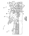
- FIG. 1 shows an example of one known turbine engine 10 having a compressor section 12, a combustor section 14 and a turbine section 16.
- the turbine section 16 there are alternating rows of stationary airfoils 18 (commonly referred to as vanes) and rotating airfoils 20 (commonly referred to as blades).
- Each row of blades 20 is formed by a plurality of airfoils 20 attached to a disc 22 provided on a rotor 24, which includes a plurality of axially-spaced discs 22.
- the blades 20 can extend radially outward from the discs 22 and terminate in a region known as the blade tip 26.
- Each row of vanes 18 is formed by attaching a plurality of airfoils 18 to a blade ring or vane carrier 28.
- the vanes 18 can extend radially inward from the inner peripheral surface 30 of the vane carrier 28.
- the vane carrier 28 is attached to an outer casing 32, which encloses the turbine section 16 of the engine 10.
- a ring seal 34 can be attached to the inner peripheral surface 30 of the vane carrier 28.
- the ring seal 34 acts as the hot gas path guide between the rows of vanes 18 at the locations of the rotating blades 20.
- the ring seal 34 can be formed by a plurality of ring segments.
- metal isolation rings can be attached to and extend radially inward from the vane carrier 28, and the ring segments can be fixed to the isolation rings by, for example, one or more fasteners.
- Each ring seal 34 can substantially surround a row of blades 20 such that the tips 26 of the rotating blades 20 are in close proximity to the ring seal 34.
- the space between the blade tips 26 and the ring seal 34 is referred to as the blade tip clearance C.
- the blade tip clearances C can further be affected by the differing rates of thermal expansion of the stationary components.
- the ring seal 34 is a relatively thin component compared to the other stationary components to which it is operatively connected (i.e., the vane carrier 28 and the outer casing 32).
- the ring seal 34 itself may be able to respond relatively rapidly to operational temperature increases, further radial movement and/or expansion of the ring seal 34 can be impeded by the relatively slower thermal response of the vane carrier 28 and/or outer casing 32.
- the outer casing 32 and the vane carrier 28 become sufficiently heated and expand radially outward. Because the ring seal 34 is connected to the vane carrier 28 and outer casing 32, the radial expansion of the vane carrier 28 and outer casing 32 can move the ring seal 34 radially outward as well so as to increase the clearances C. At steady state engine operation, such as at base load, the clearances C can become overly large, thereby reducing the efficiency of the engine 10.
- aspects of the invention are directed to a system for attaching a vane carrier and a ring seal so that axial and circumferential movement of the ring seal is substantially restricted while relative radial movement between the ring seal and the vane carrier is permitted.
- the vane carrier has an inner peripheral surface.
- a forward isolation ring and an aft isolation ring are attached to the vane carrier such that the isolation rings extend substantially circumferentially about and substantially radially inward from the inner peripheral surface of the vane carrier.
- the aft isolation ring is spaced axially downstream of the forward isolation ring.
- the ring seal has an outer periphery and an inner periphery.
- the ring seal has a plurality of substantially circumferentially spaced slots, which extend substantially axially through the ring seal and radially inward from the outer periphery.
- the system further includes a plurality of pins. Each pin substantially passes through a respective slot in the ring seal and operatively engages the forward and aft isolation rings.
- the ring seal is structurally connected to the vane carrier by the isolation ring and the pins.
- At least one of the slots and the pins can be at least partially coated with a wear resistant material; that is, either the slots or the pins or both have such a coating.
- Each of the isolation rings can include a plurality of circumferentially spaced holes.
- the holes in the forward isolation ring can be substantially aligned with the holes in the aft isolation ring.
- the ring segment can be positioned such that each slot is substantially aligned with a pair of aligned holes in the isolation rings.
- Each pin can be received within the aligned holes of the isolation rings.
- the ring seal can include a forward span, an aft span and an axial extension connecting the forward and aft spans.
- the axial extension can define at least a part of the inner periphery of the ring seal.
- the ring seal can have a substantially U-shaped cross-section.
- Each of the isolation rings can include an axial upstream surface and an axial downstream surface.
- Each of the spans of the ring seal can include an axial forward surface and an axial aft surface.
- Each pin can include a first end with a head and a second end.
- the ring seal can be positioned such that the downstream surface of the forward isolation ring opposes the forward surface of the forward span, and such that the aft surface of the aft span opposes the upstream surface of the aft isolation ring.
- the head of each pin can operatively engage one of the aft face of the aft isolation ring and the forward face of the forward isolation ring.
- the second end of the pin can be operatively connected to the other of the forward isolation ring and the aft isolation ring.
- the ring seal can be positioned such that the forward face of the forward span opposes the aft face of the forward isolation ring, and such that the forward face of the aft span opposes the aft face of the aft isolation ring.
- the head of each pin can operatively engage the aft face of the aft span, and the second end of the pin can be operatively connected to the forward isolation ring.
- the ring seal can be positioned such that the aft face of the forward span opposes the forward face of the forward isolation ring, and such that the aft face of the aft span opposes the forward face of the aft isolation ring.
- the head of each pin can operatively engage the aft face of the aft isolation ring, and the second end of the pin can be operatively connected to the forward isolation ring.
- the second end of the pin can extend through the forward isolation ring and at least partly into one of the slots in the ring seal.
- the ring seal and the vane carrier can each be made of a material with an associated coefficient of thermal expansion. Ideally, the coefficient of thermal expansion of the ring seal is less than the coefficient of thermal expansion of the vane carrier. In one embodiment, the ring seal can be made of ceramic.
- aspects of the invention are directed to an attachment system.
- the system includes a vane carrier and a ring seal enclosed within the vane carrier.
- the ring seal is operatively connected to the vane carrier so that the vane carrier and the ring seal move at least partially independent of each other in the radial direction.
- axial movement and/or circumferential movement of the ring seal can be substantially restricted.
- the ring seal and the vane carrier can each be made of a material with an associated coefficient of thermal expansion.
- the coefficient of thermal expansion of the ring seal can be less than the coefficient of thermal expansion of the vane carrier.
- the ring seal can be made of ceramic.
- the vane carrier can have an inner peripheral surface.
- the ring seal can have an axial forward side and an axial aft side.
- a plurality of protrusions can extend substantially axially from and substantially circumferentially about each axial side of the ring seal.
- the system can further include a forward isolation ring and an aft isolation ring spaced axially downstream of the forward isolation ring.
- the isolation rings can be attached to the vane carrier such that the isolation rings extend substantially circumferentially about and radially inward from the inner peripheral surface of the vane carrier.
- a plurality of protrusions can extend substantially axially from and substantially circumferentially about each of the isolation rings.
- the protrusions on the axial forward side of the ring seal can substantially matingly engage the protrusions on the forward isolation ring.
- the protrusions on the axial aft side of the ring seal can substantially matingly engage the protrusions on the aft isolation ring.
- the substantially matingly engaging protrusions of the ring seal and the isolation rings can be configured as a Hirth coupling.
- the isolation rings can be adapted to apply a clamping force on the ring seal.
- Each of the forward and aft isolation rings can include a front face and an aft face; the plurality of protrusions can be provided on the aft face of the forward isolation ring and the front face of the aft isolation ring.
- the system can further include a plurality of pins and a plurality of radial springs.
- Each of the pins can extend radially between and into operatively engagement with the ring seal and the vane carrier.
- Each spring can be located substantially proximate one of the pins. Each spring can operatively engage the vane carrier and the ring seal.
- the ring seal can have an outer peripheral surface and can include a plurality of recesses extending radially inward from the outer peripheral surface.
- Each pin can have a first end and a second end. The first end of each pin can be connected to the vane carrier, and the second end of each pin can be received within one of the recesses in the ring seal.
- the vane carrier can include a plurality of radial passages. At least a portion of each pin, including the first end, can be received within one of the passages.
- the pin and the passage can be connected by, for example, threaded engagement.
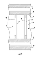
- Embodiments of the invention are directed to a system for attaching a ring seal to a vane carrier. Aspects of the invention will be explained in connection with various attachment systems, but the detailed description is intended only as exemplary. Embodiments of the invention are shown in FIGS. 2-10 , but the present invention is not limited to the illustrated structure or application. At the outset, it is noted that use herein of the terms “circumferential,” “radial” and “axial” and variations thereof is intended to mean relative to the turbine.
- a ring seal can be operatively connected to the vane carrier so as to permit relative radial movement of the ring seal and vane carrier.
- the vane carrier and the ring seal can thermally expand and contract independently of each other in the radial direction.
- the ring seal and the vane carrier can further be configured to substantially restrain axial movement of the ring seal in the axial forward and/or axial rearward directions.
- the ring seal and the vane carrier can be configured to substantially restrain circumferential movement of the ring seal in the clockwise and/or counter-clockwise directions.
- the vane carrier 40 can be attached to the turbine outer casing 42 in any of the manners known in the art.
- the vane carrier 40 has an inner peripheral surface 41.
- the vane carrier 40 can provide a forward isolation ring 44 and an aft isolation ring 46.
- the isolation rings 44, 46 and the vane carrier 40 can be a unitary construction, or the isolation rings 44, 46 can be attached to the vane carrier 40 in any of a number of known ways, such as by providing hooks (not shown) on the isolation rings 44, 46 that are received in a slot (not shown) provided in the vane carrier 40.
- the isolation rings 44, 46 can extend radially inward from the inner peripheral surface 41 of the vane carrier 40.
- the isolation rings 44, 46 can extend about the entire inner peripheral surface 41 of the vane carrier 40; that is, the isolation rings 44, 46 can form a substantially 360 degree ring.
- the isolation rings 44, 46 can have various configurations.
- each isolation ring 44, 46 can be a single piece.
- each isolation ring 44, 46 can be formed by two or more segments (not shown). For instance, two or more isolation ring segments can be substantially circumferentially abutted and/or can be joined by mechanical engagement or by one or more fasteners.
- Each of the isolation rings 44, 46 can have a forward axial surface 48 and an aft axial surface 50.
- the forward and aft axial surfaces 48, 50 can be substantially flat, or they can include one or more protrusions, bends or other non-flat features.
- the isolation rings 44, 46 can have various cross-sectional shapes. In one embodiment, the portion of the isolation rings 44, 46 that extends radially inward from the inner peripheral surface 41 of the vane carrier 40 can be substantially rectangular, but other configurations are possible.
- the forward and aft isolation rings 44, 46 may or may not be substantially identical to each other at least in any of the above-described respects.
- a ring seal 52 is attached to the vane carrier 40.
- a ring seal 52 can be formed by one or more ring segments 54.
- the segments 54 can be substantially circumferentially adjacent to each other to form a ring.
- the individual segments 54 may or may not be connected to neighboring segments 54 by, for example, bolts or other fasteners.
- the ring seal 52 can be made of two substantially 180 degree segments 54.
- the ring seal 52 can have a radial outer periphery 56 and a radial inner periphery 58.
- the ring seal 52 can have an axial upstream surface 60 and an axial downstream surface 62.
- the ring seal 52 can be substantially solid with a substantially rectangular cross-sectional shape.
- the ring seal 52 can be formed by a forward span 64 and an aft span 66 joined by a substantially axial extension 68.
- the forward span 64 can define the axial upstream face 60 of the ring segment 52 and can include an aft face 65.
- the aft span 66 can define the axial downstream surface 62 of the ring seal 52 and can include a forward face 67.
- the axial extension 68 can define the inner periphery 58 of the ring seal 52.
- the ring seal 52 can be generally U-shaped in cross-section, as shown in FIG. 4 .
- the ring seal 52 can have a plurality of slots 70 extending substantially radially inward from the outer periphery 56.
- the slots 70 can be formed by substantially aligned cutouts 72 in the forward and aft spans 64, 66.
- the slots 70 can also include a volume of space 74 between the cutouts 72 substantially bounded by a projection of each cutout 72 onto the opposite span 64 or 66.
- Each of the slots 70 can extend radially inward substantially the same distance from the outer periphery 56.
- the walls of the slots 70 are substantially smooth.
- the slots 70 can have almost any conformation.
- the slots 70 can be generally V-shaped.
- the slots 70 can be substantially rectangular or semi-ovular.
- the slots 70 can be substantially identical in size and shape, or at least one of the slots 70 can be different in at least one of these aspects.
- the slots 70 can be arranged in various ways about the ring seal 52. For instance, the slots 70 can be substantially equally spaced. However, one or more slots 70 can be unequally spaced from the rest of the slots 70.
- the ring seal 52 can be made of various materials.
- the ring seal 52 can be made of a metal alloy.
- the ring seal 52 can be made of a material with a lower coefficient of thermal expansion than the material of the vane carrier 40 to which it is attached.
- the ring seal 52 can be made of a ceramic material including ceramic matrix composites.
- the ring seal 52 can be attached to the vane carrier 40 or by way of the forward and aft isolation rings 44, 46. According to aspects of the invention, the ring seal 52 can be attached to the isolation rings 44, 46 by a plurality of pins 76.
- the quantity of pins 76 can correspond to the quantity of slots 70 in the ring seal 52.
- the pins 76 can be made of any material. In one embodiment, the pins 76 can be made of the same material as the isolation rings 44, 46.
- the pins 76 can have almost any cross-sectional shape, such as circular, rectangular, triangular or polygonal, just to name a few possibilities. Preferably, the pins 76 are substantially straight.
- the pins 76 can be sized as needed.
- the pins 76 can include a first end 78 and a second end 80. The first end 78 of the pin 76 can include a head 82.
- each of the forward and aft isolation rings 44, 46 can provide a plurality of substantially axially-extending openings 84, which may or may not extend completely through the isolation rings 44, 46.
- Each opening 84 in the forward isolation ring 44 can be sufficiently aligned with a respective opening 84 in the aft isolation ring 46 such that one of the pins 76 can be simultaneously received in each opening 84.
- the pins 76 can engage the isolation rings 44, 46 in various ways.
- the head 82 of the pin 76 can bear against the aft surface 50 of the aft isolation ring 46, and the second end 80 of the pin 76 can be secured to the forward isolation ring 44.
- the second end 80 of the pin 76 can be secured to the forward isolation ring 44 by threaded engagement.
- the second end 80 of the pin 76 can be secured to the forward isolation ring 44 by fasteners such as a cotter pin, a nut or other retainer. It will be appreciated that the opposite arrangement can be provided in which the head 82 of the pin 76 can bear against the forward isolation ring 44, and the second end 80 of the pin 76 can be secured to the aft isolation ring 46, as described above.
- any wear that may arise due to the engagement between the pins 76 and the slots 70 can be minimized by coating at least a portion of the slot 70 with a wear resistant material 71.
- the pins 70 can also be coated with a wear resistant material 71.
- the wear resistant coating 71 can be applied to the contacting surfaces of the ring seal 52 and the isolation rings 44, 46.
- the ring seal 52 can be positioned so that the slots 70 are substantially aligned with the openings 84 in the isolation rings 44, 46.
- each pin 76 can pass through one of the slots 70 in the ring seal 52 and engage both of the isolation rings 44, 46.
- the ring seal 52 can operatively engage the isolation rings 44, 46 in various ways.
- the forward isolation ring 44 can be located axially upstream of the upstream surface 60 of the ring seal 52; the aft isolation ring 46 can be located axially downstream of the downstream surface 62 of the ring seal 52.
- the aft surface 50 of the forward isolation ring 44 can face opposite the upstream surface 60 of the ring seal 52, and the downstream surface 62 of ring seal 52 can face opposite the forward surface 48 of the aft isolation ring 46.
- the forward isolation ring 44 can be located axially upstream of the upstream surface 60 of the ring seal 52, and the aft isolation ring 46 can be located axially upstream of the downstream surface 62 of the ring seal 52.
- the forward surface 60 of the forward span 64 can face opposite the aft surface 50 of the forward isolation ring 44, and the upstream surface 67 of the aft span 66 can face opposite the aft surface 50 of the aft isolation ring 46.
- the pins 76 can extend through the aft span 66, the aft isolation ring 44, the forward span 64 and at least partly into the forward isolation ring 44.
- the head 82 of the pin 76 operatively engage the downstream surface 62 of the ring seal 52.
- the head 76 can directly bear against the downstream surface 62, or a washer (not shown) or other fastener can be positioned between the head 82 of the pin 76 and the downstream surface 62 of the ring seal 52.
- the forward isolation ring 44 can be located axially downstream of the upstream surface 60 of the ring seal 52, and the aft isolation ring 46 can be located axially downstream of the downstream surface 62 of the ring seal 52.
- the aft surface 65 of the forward span 64 can face opposite the forward surface 48 of the forward isolation ring 44, and the downstream surface 62 of the ring seal 52 can face opposite the forward surface 48 of the aft isolation ring 46.
- the pins 76 can extend through the forward isolation ring 44 and at least partly into the slot 70 in the forward span 64 of the ring seal 52.
- the first embodiment of the attachment system allows radial movement of the ring seal 52, while substantially restricting circumferential and axial movement.
- the circumferential restraint provided by the pins 76 can prevent the ring seal 52 from dropping due to gravity or from shifting to the left or right.
- axial movement of the ring seal 52 can be substantially restricted by isolation rings 44, 46.
- the aft isolation ring 46 can provide the axial restraint because, during engine operation, the hot gases traveling through the turbine section 16 can force the ring seal 52 axially downstream and into engagement with the aft isolation ring 46.
- axial restraint can be provided by the head 82 of the pin 76.
- the ring seal 52 can be made of a plurality of ring segments 54. There can be any number of segments 54 as long as the segments 54 can cooperate to substantially restrict all non-radial movement and rotation.
- the outer casing 32, the vane carrier 40 and the ring seal 52 are substantially ring-shaped in cross-section. Therefore, in response to an increase in temperature, these components will grow radially outward.
- the ring seal 52 is permitted to radially expand and contract independently of the outer casing 32 and the vane carrier 40. Though relative radial motion is allowed, the slot 70 and pin 76 configuration can provide a sufficient structural connection between the vane carrier 40 and the ring segment 52.
- the attachment system according to the first embodiment of the invention can result in appreciable time savings during installation of the ring seal 52. Similarly, time can be saved in the removal of the ring seal 52.
- the pins 76 can be removed and the segment 54 can be removed from the vane carrier 40.
- the vane carrier 40 may need to be removed from the engine prior to assembly or removal of the ring seal 52.
- the attachment system according to aspects of the invention can be applied in new engine designs, and it can be retrofitted in existing engines.
- FIGS. 6-8 Another embodiment of a ring seal attachment system according to aspects of the invention is shown in FIGS. 6-8 .
- the system includes a vane carrier 40 having an inner peripheral surface 41.
- the vane carrier 40 can provide a forward isolation ring 44 and an aft isolation ring 46.
- the earlier discussion of these components applies equally here.
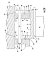
- each of the isolation rings 44, 46 can be equipped with a plurality of substantially axially extending protrusions 90.
- the protrusions 90 can extend substantially circumferentially (that is, substantially 360 degrees) around each isolation ring 44, 46.
- the protrusions 90 are substantially equally spaced about each isolation ring 44, 46.
- the protrusions 90 can be provided on the aft surface 50 of the forward isolation ring 44 as well as on the forward surface 48 of the aft isolation ring 46.
- the protrusions 90 can be provided on other surfaces on the isolation rings 44, 46 or on different combinations of surfaces on the isolation rings 44, 46.
- the protrusions 90 can have any of a number of configurations.
- the protrusions 90 can be substantially rectangular, but other conformations, such as triangular, are possible.
- the protrusions 90 can be configured as gear-like teeth.
- Each of the protrusions 90 can be substantially identical, or one or more of the protrusions 90 can be different from the other protrusions 90 in terms of size and shape.
- the protrusions 90 can be provided in the isolation rings 44, 46 by, for example, machining.
- the system can include a ring seal 52. It is noted that FIG. 6 shows the ring seal 52 as being made of two ring segments 54 that are substantially circumferentially adjacent to each other. In one embodiment, the segments 54 can be joined by, for example, fasteners 86.
- the ring seal 52 can have a radial outer periphery 56 and a radial inner periphery 58. The outer periphery 56 can be defined by a flange 88.
- the upstream surface 60 and the downstream surface 62 of the ring seal 52 can include a plurality of protrusions 92 extending substantially axially therefrom.
- the protrusions 92 can extend substantially circumferentially (that is, substantially 360 degrees) around each surface 60, 62 of the ring seal 52.
- the foregoing description of the protrusions 90 in connection with the isolation rings 44, 46 is equally applicable to the protrusions 92.
- the protrusions 92 on the ring seal 52 can be located at or near the outer periphery 56 of the ring seal 52.
- the protrusions 92 on the ring seal 52 and the protrusions on the isolation rings 44, 46 can be configured to substantially matingly engage each other.
- the protrusions 90, 92 are configured as a Hirth coupling 93.
- the ring segment 52 can be positioned such that the protrusions 92 on the upstream and downstream surfaces 60, 62 thereof substantially matingly engage the protrusions 90 provided on the isolation rings 44, 46.
- the protrusions 92 on the upstream face 60 of the ring seal 52 can substantially matingly engage the protrusions 90 on the aft surface 50 of the forward isolation ring 44.
- the protrusions 92 on the downstream face 62 of the ring seal 52 can substantially matingly engage the protrusions 90 of the forward surface 48 of the aft isolation ring 46.
- At least one of the isolation rings 44, 46 can be made of two or more portions.
- the forward isolation ring 44 can be formed by two portions 44a, 44b joined together by, for example, a bolt 94 or other fastener.
- the bolt 94 can also be used to keep the ring seal 52 compressed between the two isolation rings 44, 46.
- axial and circumferential movement of the ring seal 52 is substantially restrained because of the substantially matingly engagement of the protrusions 90, 92, as described above.
- the same arrangement does not prohibit relative radial motion of the ring seal 52 and isolation rings 44, 46.
- the differential rates of thermal expansion and contraction of the ring seal 52 and the vane carrier 40 and/or outer casing can be accommodated.
- any radial movement of the isolation rings 44, 46 and/or the vane carrier 40 does not substantially affect the radial position and movement of the ring seal 52.
- the isolation rings 44, 46 and the ring seal 52 are structurally connected.
- the substantially mating engagement of the protrusions 90, 92 can allow the ring seal 52 to be substantially self-centering on the vane carrier 40.
- the protrusions 90, 92 being configured to be substantially matingly engaging, the ring seal 52 can be substantially centered on the vane carrier 40 when the ring seal 52 reseats itself.
- aspects of the invention can minimize the need for systems to actively maintain the ring seal 52 centered on the vane carrier 40.
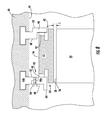
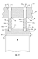
- FIGS. 9-10 Another attachment system according to aspects of the invention is shown in FIGS. 9-10 .
- the vane carrier 40 and the ring seal 52 can be operatively connected by a plurality of radial pins 110.
- the pins 110 can operatively engage the vane carrier 40 and the ring seal 52.
- Each pin can have a first end 114 and a second end 116.
- the pins 110 can be substantially straight.
- the pins 110 can have almost any cross-sectional geometry.
- the pins 110 can be substantially circular, but they can also be, for example, substantially oval, rectangular, triangular and polygonal.
- At least a portion of each pin can be adapted for operative engagement with the ring seal 52 and/or the vane carrier 40, as will be explained in greater detail below.
- a portion of each pin 110 can be threaded 111.
- Each of the plurality of pins 110 can be identical, or at least one of the pins 110 can be different from the other pins 110 in one or more respects.
- the vane carrier 40 can be adapted for operative engagement with each pin 110.
- the vane carrier 40 can include a plurality of passages 112.
- the passages 112 can extend radially outward from the inner peripheral surface 41 of the vane carrier 40, as shown in FIG. 10 .
- the passages 112 can extend substantially radially through the vane carrier 40.
- At least a portion of a pin 110 can be received in the passage 112.
- the passages 112 and the pins 110 are closely toleranced to minimize axial and circumferential movement of the pins 110 within the passages 112.
- the pins 110 and the vane carrier 40 can be connected to each other.
- at least a portion of the passages can include threads 117 to engage the threads 111 provided at or near the first end 114 of each of the pins 110, as shown in FIG. 10 .
- the pins 110 can be inserted and removed from the vane carrier 40 from the radially outer surface 119 of the vane carrier 40.
- threaded engagement is only one of several ways in which the pins 110 can operatively engage the vane carrier 40, and aspects of the invention are not limited to threaded engagement.
- the second end 116 of the pins 110 can extend radially inward from the inner peripheral surface 41 of the vane carrier 40.
- a plurality of recesses 115 can be provided in the ring seal 52.
- the recesses 115 can extend radially inward from the outer periphery 56 of the ring seal 52.
- the recesses 115 and the passages 112 can be provided in the ring seal 52 and the vane carrier 40, respectively, using various conventional machining techniques.
- the pins 110 can engage the recesses 115 in various ways.
- each recess 115 can receive a portion of a pin 110 including the second end 116.
- the pins 110 can be free to move radially within the recess 115.
- the pins 110 are substantially restricted from moving axially and circumferentially in the recesses 115, which would cause the ring seal 52 to move axially and circumferentially.
- the recesses 115 can be sized and shaped so as to be closely toleranced with the pins 110 to thereby minimizing axial and circumferential movement of the pins 110 in the recess 115.
- the ring seal 52 can be removed from the vane carrier 40 by removing the pins 110.
- the recesses 115 can be arranged in various ways. For instance, the recesses 115 can be substantially equally spaced circumferentially about the ring seal 52 and the vane carrier 40. In some instances, one or more recesses 115 can be unequally spaced from the other recesses 115. Further, the recesses can be substantially aligned 115 in a row about each component. Alternatively, one or more of the recesses 115 can be axially offset from the other recesses 115. There can be two or more rows of recesses 115. FIG. 10 shows an embodiment in which there is a first row of recesses 113a and a second row of recesses 113b.
- the arrangement of the recesses 115 in the first row 113a may or may not be substantially identical to the arrangement of the recesses 115 in the second row 113b.
- Each recess 115 in the ring seal 52 can be substantially aligned with one of the passages 112 in the vane carrier 40.
- One or more radial springs can be operatively associated with each pin 110 such that the pins 110 are spring loaded.
- the radial springs can be coiled springs 118, which operatively engage the ring seal 52 and the vane carrier 40.
- the pins 110 can pass through each coiled spring 118.
- the radial springs can provide a substantially steady load against the ring seal 52.
- the radial springs can keep the ring seal 52 substantially centered and may be able to minimize vibrations.
- the radial springs can also overcome any friction between the pin 110 and the recesses 115 so that radial growth is not substantially impeded.
- the pins 110 according to aspects of the invention can axially and circumferentially restrain the ring seal 52. However, the radial pins 110 permit differential thermal growth between the ring seal 52 and the vane carrier 40.
- each of the embodiments of the attachment system can facilitate the optimization of the operational blade tip clearances C by allowing the ring seal 52 to radially grow and contract independently of the vane and/or the outer casing 42.
- a pinch point occurs during engine operation, only the further radial growth of the ring seal 52 can increase the clearance C between the inner periphery 58 of the ring seal 52 and the tips 26 of a neighboring row of blades 20.
- the clearance C is substantially unaffected by radial growth of the vane carrier 40 and/or the outer casing 32, which may thermally expand at a slower rate than the ring seal 52 because of their relatively large thickness compared to the ring seal 52.
- the ring seal 52 can made of a material with a low coefficient of thermal expansion (at least compared to the vane carrier 40 and the outer casing 32).
- the clearances C can be minimized purely from the geometry and the thermal properties of the ring seal 52.
- the attachment systems according to aspects of the invention can minimize or eliminate the need for control systems to monitor the tip clearances, or hydraulics or pressure systems to actively adjust the clearances.
- the ring seal 52 will respond much quicker to the initial firing of the engine, resulting in a faster thermal growth rate which can change the time at which the pinch point occurs.
- Postponement of the pinch point can reduce the concerns associated with pinch points. Potentially, the pinch point would be delayed until steady state engine operation, which would be the ideal operational condition for having minimal blade tip clearances C.
- the thermal expansion of the stationary and rotating components that establish the blade tip clearance C has substantially stabilized, so that concerns of blade tip rubbing are reduced.
- Minimized blade tip clearances C at steady state engine operation, such as base load would increase engine performance and efficiency.
Landscapes
- Engineering & Computer Science (AREA)
- Mechanical Engineering (AREA)
- General Engineering & Computer Science (AREA)
- Turbine Rotor Nozzle Sealing (AREA)
Applications Claiming Priority (2)
| Application Number | Priority Date | Filing Date | Title |
|---|---|---|---|
| US11/165,367 US7494317B2 (en) | 2005-06-23 | 2005-06-23 | Ring seal attachment system |
| EP06749972A EP1893846B1 (de) | 2005-06-23 | 2006-04-13 | Ringdichtungsbefestigungssystem |
Related Parent Applications (1)
| Application Number | Title | Priority Date | Filing Date |
|---|---|---|---|
| EP06749972.3 Division | 2006-04-13 |
Publications (2)
| Publication Number | Publication Date |
|---|---|
| EP2154335A1 true EP2154335A1 (de) | 2010-02-17 |
| EP2154335B1 EP2154335B1 (de) | 2011-07-20 |
Family
ID=36843275
Family Applications (2)
| Application Number | Title | Priority Date | Filing Date |
|---|---|---|---|
| EP06749972A Expired - Lifetime EP1893846B1 (de) | 2005-06-23 | 2006-04-13 | Ringdichtungsbefestigungssystem |
| EP09173774A Expired - Lifetime EP2154335B1 (de) | 2005-06-23 | 2006-04-13 | Ringdichtungsbefestigungssystem |
Family Applications Before (1)
| Application Number | Title | Priority Date | Filing Date |
|---|---|---|---|
| EP06749972A Expired - Lifetime EP1893846B1 (de) | 2005-06-23 | 2006-04-13 | Ringdichtungsbefestigungssystem |
Country Status (4)
| Country | Link |
|---|---|
| US (1) | US7494317B2 (de) |
| EP (2) | EP1893846B1 (de) |
| DE (1) | DE602006020721D1 (de) |
| WO (1) | WO2007001591A1 (de) |
Cited By (1)
| Publication number | Priority date | Publication date | Assignee | Title |
|---|---|---|---|---|
| IT201900023850A1 (it) * | 2019-12-12 | 2021-06-12 | Nuovo Pignone Tecnologie Srl | Struttura di tenuta composita per una macchina, e metodo per produrre la struttura di tenuta composita |
Families Citing this family (87)
| Publication number | Priority date | Publication date | Assignee | Title |
|---|---|---|---|---|
| US7563071B2 (en) * | 2005-08-04 | 2009-07-21 | Siemens Energy, Inc. | Pin-loaded mounting apparatus for a refractory component in a combustion turbine engine |
| US20090324393A1 (en) * | 2007-01-25 | 2009-12-31 | Siemens Power Generation, Inc. | Ceramic matrix composite turbine engine component |
| US7824152B2 (en) * | 2007-05-09 | 2010-11-02 | Siemens Energy, Inc. | Multivane segment mounting arrangement for a gas turbine |
| US8061977B2 (en) * | 2007-07-03 | 2011-11-22 | Siemens Energy, Inc. | Ceramic matrix composite attachment apparatus and method |
| EP2194234A1 (de) * | 2008-12-03 | 2010-06-09 | Siemens Aktiengesellschaft | Wärmeisolationsring zur passiven Spaltkontrolle in einer Gasturbine |
| US8382436B2 (en) | 2009-01-06 | 2013-02-26 | General Electric Company | Non-integral turbine blade platforms and systems |
| US8262345B2 (en) | 2009-02-06 | 2012-09-11 | General Electric Company | Ceramic matrix composite turbine engine |
| US8636465B2 (en) * | 2009-10-01 | 2014-01-28 | Pratt & Whitney Canada Corp. | Gas turbine engine thermal expansion joint |
| US8453464B2 (en) * | 2009-10-01 | 2013-06-04 | Pratt & Whitney Canada Corp. | Air metering device for gas turbine engine |
| US8529201B2 (en) * | 2009-12-17 | 2013-09-10 | United Technologies Corporation | Blade outer air seal formed of stacked panels |
| US8794640B2 (en) * | 2010-03-25 | 2014-08-05 | United Technologies Corporation | Turbine sealing system |
| US9234431B2 (en) * | 2010-07-20 | 2016-01-12 | Siemens Energy, Inc. | Seal assembly for controlling fluid flow |
| GB2477825B (en) * | 2010-09-23 | 2015-04-01 | Rolls Royce Plc | Anti fret liner assembly |
| US8347636B2 (en) | 2010-09-24 | 2013-01-08 | General Electric Company | Turbomachine including a ceramic matrix composite (CMC) bridge |
| US8920113B2 (en) * | 2011-11-28 | 2014-12-30 | United Technologies Corporation | Thermal gradiant tolerant turbomachine coupling member |
| US9726043B2 (en) | 2011-12-15 | 2017-08-08 | General Electric Company | Mounting apparatus for low-ductility turbine shroud |
| CA2825849A1 (en) | 2011-12-29 | 2013-07-04 | Elliott Company | Hot gas expander inlet casing assembly and method |
| US9133724B2 (en) * | 2012-01-09 | 2015-09-15 | General Electric Company | Turbomachine component including a cover plate |
| US9200530B2 (en) * | 2012-07-20 | 2015-12-01 | United Technologies Corporation | Radial position control of case supported structure |
| US9528376B2 (en) * | 2012-09-13 | 2016-12-27 | General Electric Company | Compressor fairing segment |
| WO2014158276A2 (en) | 2013-03-05 | 2014-10-02 | Rolls-Royce Corporation | Structure and method for providing compliance and sealing between ceramic and metallic structures |
| CA2897965C (en) | 2013-03-11 | 2020-02-25 | Rolls-Royce Corporation | Compliant intermediate component of a gas turbine engine |
| US9790863B2 (en) | 2013-04-05 | 2017-10-17 | Honeywell International Inc. | Fluid transfer seal assemblies, fluid transfer systems, and methods for transferring process fluid between stationary and rotating components using the same |
| CA2912428C (en) | 2013-05-17 | 2018-03-13 | General Electric Company | Cmc shroud support system of a gas turbine |
| WO2014204574A2 (en) * | 2013-06-21 | 2014-12-24 | United Technologies Corporation | Seals for gas turbine engine |
| US9267387B2 (en) * | 2013-07-15 | 2016-02-23 | General Electric Company | Seal platform |
| EP3080403B1 (de) | 2013-12-12 | 2019-05-01 | General Electric Company | Trägersystem für cmc-mantel |
| CN106460543B (zh) | 2014-06-12 | 2018-12-21 | 通用电气公司 | 多件式护罩悬挂器组件 |
| CA2951638A1 (en) | 2014-06-12 | 2015-12-17 | General Electric Company | Shroud hanger assembly |
| EP3155229B1 (de) * | 2014-06-12 | 2020-03-18 | General Electric Company | Ummantelungsaufhängeranordnung |
| CA2951425C (en) | 2014-06-12 | 2019-12-24 | General Electric Company | Shroud hanger assembly |
| US10215044B2 (en) * | 2014-08-08 | 2019-02-26 | Siemens Energy, Inc. | Interstage seal housing optimization system in a gas turbine engine |
| US20160047549A1 (en) * | 2014-08-15 | 2016-02-18 | Rolls-Royce Corporation | Ceramic matrix composite components with inserts |
| US10301957B2 (en) | 2014-12-17 | 2019-05-28 | United Technologies Corporation | Pinned seal |
| US10202857B2 (en) * | 2015-02-06 | 2019-02-12 | United Technologies Corporation | Vane stages |
| US9874104B2 (en) | 2015-02-27 | 2018-01-23 | General Electric Company | Method and system for a ceramic matrix composite shroud hanger assembly |
| US10309257B2 (en) | 2015-03-02 | 2019-06-04 | Rolls-Royce North American Technologies Inc. | Turbine assembly with load pads |
| FR3033825B1 (fr) * | 2015-03-16 | 2018-09-07 | Safran Aircraft Engines | Ensemble d'anneau de turbine en materiau composite a matrice ceramique |
| FR3036432B1 (fr) * | 2015-05-22 | 2019-04-19 | Safran Ceramics | Ensemble d'anneau de turbine avec maintien axial |
| FR3036436B1 (fr) * | 2015-05-22 | 2020-01-24 | Safran Ceramics | Ensemble d'anneau de turbine avec maintien par brides |
| US10370997B2 (en) | 2015-05-26 | 2019-08-06 | Rolls-Royce Corporation | Turbine shroud having ceramic matrix composite seal segment |
| US10221713B2 (en) | 2015-05-26 | 2019-03-05 | Rolls-Royce Corporation | Shroud cartridge having a ceramic matrix composite seal segment |
| US10087770B2 (en) | 2015-05-26 | 2018-10-02 | Rolls-Royce Corporation | Shroud cartridge having a ceramic matrix composite seal segment |
| US10370998B2 (en) | 2015-05-26 | 2019-08-06 | Rolls-Royce Corporation | Flexibly mounted ceramic matrix composite seal segments |
| US9963990B2 (en) | 2015-05-26 | 2018-05-08 | Rolls-Royce North American Technologies, Inc. | Ceramic matrix composite seal segment for a gas turbine engine |
| FR3041993B1 (fr) * | 2015-10-05 | 2019-06-21 | Safran Aircraft Engines | Ensemble d'anneau de turbine avec maintien axial |
| FR3055147B1 (fr) * | 2016-08-19 | 2020-05-29 | Safran Aircraft Engines | Ensemble d'anneau de turbine |
| FR3055148B1 (fr) * | 2016-08-19 | 2020-06-05 | Safran Aircraft Engines | Ensemble d'anneau de turbine |
| FR3056636B1 (fr) * | 2016-09-27 | 2020-06-05 | Safran Aircraft Engines | Ensemble d'anneau de turbine sans jeu de montage a froid |
| FR3056632B1 (fr) * | 2016-09-27 | 2020-06-05 | Safran Aircraft Engines | Ensemble d'anneau turbine comprenant un element de repartition de l'air de refroidissement |
| US10697314B2 (en) | 2016-10-14 | 2020-06-30 | Rolls-Royce Corporation | Turbine shroud with I-beam construction |
| FR3064023B1 (fr) * | 2017-03-16 | 2019-09-13 | Safran Aircraft Engines | Ensemble d'anneau de turbine |
| US10480337B2 (en) | 2017-04-18 | 2019-11-19 | Rolls-Royce North American Technologies Inc. | Turbine shroud assembly with multi-piece seals |
| CA3000376A1 (en) * | 2017-05-23 | 2018-11-23 | Rolls-Royce Corporation | Turbine shroud assembly having ceramic matrix composite track segments with metallic attachment features |
| US10557365B2 (en) | 2017-10-05 | 2020-02-11 | Rolls-Royce Corporation | Ceramic matrix composite blade track with mounting system having reaction load distribution features |
| US10815810B2 (en) * | 2019-01-10 | 2020-10-27 | Raytheon Technologies Corporation | BOAS assemblies with axial support pins |
| FR3093127B1 (fr) * | 2019-02-25 | 2021-10-22 | Safran Aircraft Engines | Assemblage de veine aérodynamique pour une turbomachine, procédés d’assemblage et de réparation de cet assemblage |
| US11149563B2 (en) | 2019-10-04 | 2021-10-19 | Rolls-Royce Corporation | Ceramic matrix composite blade track with mounting system having axial reaction load distribution features |
| US11220925B2 (en) | 2019-10-10 | 2022-01-11 | Rolls-Royce North American Technologies Inc. | Turbine shroud with friction mounted ceramic matrix composite blade track |
| US11208918B2 (en) | 2019-11-15 | 2021-12-28 | Rolls-Royce Corporation | Turbine shroud assembly with case captured seal segment carrier |
| US11053817B2 (en) | 2019-11-19 | 2021-07-06 | Rolls-Royce Corporation | Turbine shroud assembly with ceramic matrix composite blade track segments and full hoop carrier |
| US11378012B2 (en) | 2019-12-12 | 2022-07-05 | Rolls-Royce Plc | Insert-mounted turbine assembly for a gas turbine engine |
| US11066947B2 (en) | 2019-12-18 | 2021-07-20 | Rolls-Royce Corporation | Turbine shroud assembly with sealed pin mounting arrangement |
| US11073045B2 (en) | 2019-12-18 | 2021-07-27 | Rolls-Royce Corporation | Turbine shroud assembly with case captured seal segment carrier |
| US11215064B2 (en) | 2020-03-13 | 2022-01-04 | Raytheon Technologies Corporation | Compact pin attachment for CMC components |
| US11208896B1 (en) * | 2020-10-20 | 2021-12-28 | Rolls-Royce Corporation | Turbine shroud having ceramic matrix composite component mounted with cooled pin |
| US11255210B1 (en) * | 2020-10-28 | 2022-02-22 | Rolls-Royce Corporation | Ceramic matrix composite turbine shroud assembly with joined cover plate |
| FR3122210B1 (fr) * | 2021-04-21 | 2025-04-25 | Safran Aircraft Engines | Ensemble d’anneau de turbine monté sur entretoise |
| US11286812B1 (en) | 2021-05-25 | 2022-03-29 | Rolls-Royce Corporation | Turbine shroud assembly with axially biased pin and shroud segment |
| US11761351B2 (en) | 2021-05-25 | 2023-09-19 | Rolls-Royce Corporation | Turbine shroud assembly with radially located ceramic matrix composite shroud segments |
| US11629607B2 (en) | 2021-05-25 | 2023-04-18 | Rolls-Royce Corporation | Turbine shroud assembly with radially and axially biased ceramic matrix composite shroud segments |
| US11346251B1 (en) | 2021-05-25 | 2022-05-31 | Rolls-Royce Corporation | Turbine shroud assembly with radially biased ceramic matrix composite shroud segments |
| US11346237B1 (en) | 2021-05-25 | 2022-05-31 | Rolls-Royce Corporation | Turbine shroud assembly with axially biased ceramic matrix composite shroud segment |
| US11499444B1 (en) | 2021-06-18 | 2022-11-15 | Rolls-Royce Corporation | Turbine shroud assembly with forward and aft pin shroud attachment |
| US11319828B1 (en) | 2021-06-18 | 2022-05-03 | Rolls-Royce Corporation | Turbine shroud assembly with separable pin attachment |
| US11441441B1 (en) | 2021-06-18 | 2022-09-13 | Rolls-Royce Corporation | Turbine shroud with split pin mounted ceramic matrix composite blade track |
| US12031443B2 (en) | 2022-11-29 | 2024-07-09 | Rolls-Royce Corporation | Ceramic matrix composite blade track segment with attachment flange cooling chambers |
| US11773751B1 (en) | 2022-11-29 | 2023-10-03 | Rolls-Royce Corporation | Ceramic matrix composite blade track segment with pin-locating threaded insert |
| US11713694B1 (en) | 2022-11-30 | 2023-08-01 | Rolls-Royce Corporation | Ceramic matrix composite blade track segment with two-piece carrier |
| US11840936B1 (en) | 2022-11-30 | 2023-12-12 | Rolls-Royce Corporation | Ceramic matrix composite blade track segment with pin-locating shim kit |
| US11732604B1 (en) | 2022-12-01 | 2023-08-22 | Rolls-Royce Corporation | Ceramic matrix composite blade track segment with integrated cooling passages |
| US11885225B1 (en) | 2023-01-25 | 2024-01-30 | Rolls-Royce Corporation | Turbine blade track with ceramic matrix composite segments having attachment flange draft angles |
| US12209539B2 (en) | 2023-04-07 | 2025-01-28 | Rtx Corporation | Fusible gearbox support with catcher pin systems and methods |
| US12196138B2 (en) | 2023-04-07 | 2025-01-14 | Rtx Corporation | Frangible gearbox center guide support systems and methods |
| US12044181B1 (en) * | 2023-04-07 | 2024-07-23 | Rtx Corporation | Fusible gearbox center guide support with catcher pin and anti-rotation pin systems and methods |
| US12006875B1 (en) | 2023-04-07 | 2024-06-11 | Rtx Corporation | Fusible gearbox center guide support with frangible catcher pin systems and methods |
| US12421870B1 (en) | 2024-04-30 | 2025-09-23 | Rolls-Royce Corporation | Pin mounted ceramic matrix composite heat shields with impingement cooling |
Citations (7)
| Publication number | Priority date | Publication date | Assignee | Title |
|---|---|---|---|---|
| US4087199A (en) * | 1976-11-22 | 1978-05-02 | General Electric Company | Ceramic turbine shroud assembly |
| US5228828A (en) * | 1991-02-15 | 1993-07-20 | General Electric Company | Gas turbine engine clearance control apparatus |
| US5423659A (en) * | 1994-04-28 | 1995-06-13 | United Technologies Corporation | Shroud segment having a cut-back retaining hook |
| GB2343224A (en) * | 1998-09-28 | 2000-05-03 | Gen Electric | Turbine inner shroud and attachment arrangement |
| EP1350927A2 (de) * | 2002-03-28 | 2003-10-08 | General Electric Company | Mantelringsegment, Herstellungsverfahren eines Mantelringsegments, sowie Mantelringanordnung für ein Turbinentriebwerk |
| EP1408200A2 (de) * | 2002-10-10 | 2004-04-14 | Rolls-Royce Deutschland Ltd & Co KG | Turbinendeckbandsegmentbefestigung |
| US20050129499A1 (en) * | 2003-12-11 | 2005-06-16 | Honeywell International Inc. | Gas turbine high temperature turbine blade outer air seal assembly |
Family Cites Families (24)
| Publication number | Priority date | Publication date | Assignee | Title |
|---|---|---|---|---|
| FR981975A (fr) * | 1943-05-21 | 1951-06-01 | Rateau Soc | Perfectionnement aux turbines à gaz |
| US2638743A (en) * | 1949-04-29 | 1953-05-19 | Ruston & Hornsby Ltd | Construction of turbine-inlet and stator elements of gas turbines |
| US3807891A (en) | 1972-09-15 | 1974-04-30 | United Aircraft Corp | Thermal response turbine shroud |
| DE2250484A1 (de) | 1972-10-14 | 1974-04-18 | Bulawin | Stator der mehrstufen-stroemungsmaschine |
| US3829233A (en) | 1973-06-27 | 1974-08-13 | Westinghouse Electric Corp | Turbine diaphragm seal structure |
| US4131388A (en) * | 1977-05-26 | 1978-12-26 | United Technologies Corporation | Outer air seal |
| US4274805A (en) | 1978-10-02 | 1981-06-23 | United Technologies Corporation | Floating vane support |
| US4337016A (en) | 1979-12-13 | 1982-06-29 | United Technologies Corporation | Dual wall seal means |
| US4551064A (en) | 1982-03-05 | 1985-11-05 | Rolls-Royce Limited | Turbine shroud and turbine shroud assembly |
| JPS58206807A (ja) * | 1982-05-28 | 1983-12-02 | Hitachi Ltd | 軸流タ−ビンの動翼先端すき間制御装置 |
| US4576548A (en) * | 1984-01-17 | 1986-03-18 | Westinghouse Electric Corp. | Self-aligning static seal for gas turbine stator vanes |
| US4566851A (en) | 1984-05-11 | 1986-01-28 | United Technologies Corporation | First stage turbine vane support structure |
| EP0382333B1 (de) | 1989-01-09 | 1993-06-30 | Northern Engineering Industries Plc | Befestigung und Anordnung von segmentförmigen Elementen in Turbomaschinen |
| GB2249356B (en) | 1990-11-01 | 1995-01-18 | Rolls Royce Plc | Shroud liners |
| GB9210642D0 (en) | 1992-05-19 | 1992-07-08 | Rolls Royce Plc | Rotor shroud assembly |
| AU5732899A (en) | 1998-08-12 | 2000-03-06 | Etn Prazisionstechnik Gmbh | Support devices for the vanes of power units |
| JP4301692B2 (ja) | 2000-03-31 | 2009-07-22 | 三菱重工業株式会社 | ガスタービン |
| US6382905B1 (en) * | 2000-04-28 | 2002-05-07 | General Electric Company | Fan casing liner support |
| FR2819010B1 (fr) | 2001-01-04 | 2004-05-28 | Snecma Moteurs | Secteur d'entretoise de support d'anneau de stator de la turbine haute pression d'une turbomachine avec rattrapage de jeux |
| JP2004036443A (ja) * | 2002-07-02 | 2004-02-05 | Ishikawajima Harima Heavy Ind Co Ltd | ガスタービンシュラウド構造 |
| US6877952B2 (en) | 2002-09-09 | 2005-04-12 | Florida Turbine Technologies, Inc | Passive clearance control |
| US6884026B2 (en) | 2002-09-30 | 2005-04-26 | General Electric Company | Turbine engine shroud assembly including axially floating shroud segment |
| US6821085B2 (en) | 2002-09-30 | 2004-11-23 | General Electric Company | Turbine engine axially sealing assembly including an axially floating shroud, and assembly method |
| US6942203B2 (en) | 2003-11-04 | 2005-09-13 | General Electric Company | Spring mass damper system for turbine shrouds |
-
2005
- 2005-06-23 US US11/165,367 patent/US7494317B2/en not_active Expired - Fee Related
-
2006
- 2006-04-13 DE DE602006020721T patent/DE602006020721D1/de not_active Expired - Lifetime
- 2006-04-13 WO PCT/US2006/013774 patent/WO2007001591A1/en not_active Ceased
- 2006-04-13 EP EP06749972A patent/EP1893846B1/de not_active Expired - Lifetime
- 2006-04-13 EP EP09173774A patent/EP2154335B1/de not_active Expired - Lifetime
Patent Citations (7)
| Publication number | Priority date | Publication date | Assignee | Title |
|---|---|---|---|---|
| US4087199A (en) * | 1976-11-22 | 1978-05-02 | General Electric Company | Ceramic turbine shroud assembly |
| US5228828A (en) * | 1991-02-15 | 1993-07-20 | General Electric Company | Gas turbine engine clearance control apparatus |
| US5423659A (en) * | 1994-04-28 | 1995-06-13 | United Technologies Corporation | Shroud segment having a cut-back retaining hook |
| GB2343224A (en) * | 1998-09-28 | 2000-05-03 | Gen Electric | Turbine inner shroud and attachment arrangement |
| EP1350927A2 (de) * | 2002-03-28 | 2003-10-08 | General Electric Company | Mantelringsegment, Herstellungsverfahren eines Mantelringsegments, sowie Mantelringanordnung für ein Turbinentriebwerk |
| EP1408200A2 (de) * | 2002-10-10 | 2004-04-14 | Rolls-Royce Deutschland Ltd & Co KG | Turbinendeckbandsegmentbefestigung |
| US20050129499A1 (en) * | 2003-12-11 | 2005-06-16 | Honeywell International Inc. | Gas turbine high temperature turbine blade outer air seal assembly |
Cited By (3)
| Publication number | Priority date | Publication date | Assignee | Title |
|---|---|---|---|---|
| IT201900023850A1 (it) * | 2019-12-12 | 2021-06-12 | Nuovo Pignone Tecnologie Srl | Struttura di tenuta composita per una macchina, e metodo per produrre la struttura di tenuta composita |
| WO2021115626A1 (en) * | 2019-12-12 | 2021-06-17 | Nuovo Pignone Tecnologie - S.R.L. | Composite seal structure for a machine, and method of manufacturing the composite seal structure |
| US11927099B2 (en) | 2019-12-12 | 2024-03-12 | Nuovo Pignone Tecnologie—S.R.L. | Composite seal structure for a machine, and method of manufacturing the composite seal structure |
Also Published As
| Publication number | Publication date |
|---|---|
| EP1893846B1 (de) | 2011-03-16 |
| WO2007001591A1 (en) | 2007-01-04 |
| EP2154335B1 (de) | 2011-07-20 |
| US7494317B2 (en) | 2009-02-24 |
| US20060292001A1 (en) | 2006-12-28 |
| DE602006020721D1 (de) | 2011-04-28 |
| EP1893846A1 (de) | 2008-03-05 |
Similar Documents
| Publication | Publication Date | Title |
|---|---|---|
| US7494317B2 (en) | Ring seal attachment system | |
| JP4495310B2 (ja) | Cクリップリテイナを有するシュラウドアセンブリ | |
| EP2543825B1 (de) | Mantelring einer Gasturbine | |
| US5372476A (en) | Turbine nozzle support assembly | |
| EP1079075B1 (de) | Stator für eine Turbomaschine | |
| US5333995A (en) | Wear shim for a turbine engine | |
| US5639210A (en) | Rotor blade outer tip seal apparatus | |
| JP5386197B2 (ja) | 内側タービンシェル支持構成及び方法 | |
| EP1104836A2 (de) | Haltefeder für Leitschaufelsektoren und deren Halterung | |
| US20030202876A1 (en) | Attachment of a ceramic shroud in a metal housing | |
| US20040115043A1 (en) | Turbine shroud segment attachment | |
| US6682307B1 (en) | Sealing system for a rotor of a turbo engine | |
| EP2964896B1 (de) | System und verfahren zur leckagevermeidung in einer turbine | |
| US9222363B2 (en) | Angular sector of a stator for a turbine engine compressor, a turbine engine stator, and a turbine engine including such a sector | |
| JPH09512322A (ja) | カットバック保持フックを有するシュラウドセグメント | |
| GB2477825A (en) | Anti-fret liner for a turbine engine | |
| US7575416B2 (en) | Rotor assembly for a rotary machine | |
| KR20070108822A (ko) | 증기 터빈용 가변성 유극 양압 패킹을 위한 인장 스프링액추에이터 | |
| US20170096903A1 (en) | Retaining device for axially retaining a blade and rotor device with such a retaining device | |
| US5118253A (en) | Compressor case construction with backbone | |
| EP3219928B1 (de) | Äussere luftdichtung für eine turbinenschaufel mit federzentrierung | |
| US20060045747A1 (en) | Compressor stator floating tip shroud and related method | |
| EP0815353B1 (de) | Abriebfeste lagerung eines dichtringes in einer gasturbine | |
| US9845698B2 (en) | Belly band seal with anti-rotation structure | |
| US20080003100A1 (en) | Methods and apparatus to facilitate sealing in a turbine |
Legal Events
| Date | Code | Title | Description |
|---|---|---|---|
| PUAI | Public reference made under article 153(3) epc to a published international application that has entered the european phase |
Free format text: ORIGINAL CODE: 0009012 |
|
| AC | Divisional application: reference to earlier application |
Ref document number: 1893846 Country of ref document: EP Kind code of ref document: P |
|
| AK | Designated contracting states |
Kind code of ref document: A1 Designated state(s): DE FR GB IT |
|
| 17P | Request for examination filed |
Effective date: 20100810 |
|
| 17Q | First examination report despatched |
Effective date: 20100909 |
|
| GRAP | Despatch of communication of intention to grant a patent |
Free format text: ORIGINAL CODE: EPIDOSNIGR1 |
|
| GRAS | Grant fee paid |
Free format text: ORIGINAL CODE: EPIDOSNIGR3 |
|
| GRAA | (expected) grant |
Free format text: ORIGINAL CODE: 0009210 |
|
| AC | Divisional application: reference to earlier application |
Ref document number: 1893846 Country of ref document: EP Kind code of ref document: P |
|
| AK | Designated contracting states |
Kind code of ref document: B1 Designated state(s): DE FR GB IT |
|
| REG | Reference to a national code |
Ref country code: GB Ref legal event code: FG4D |
|
| REG | Reference to a national code |
Ref country code: DE Ref legal event code: R096 Ref document number: 602006023245 Country of ref document: DE Effective date: 20110915 |
|
| PLBE | No opposition filed within time limit |
Free format text: ORIGINAL CODE: 0009261 |
|
| STAA | Information on the status of an ep patent application or granted ep patent |
Free format text: STATUS: NO OPPOSITION FILED WITHIN TIME LIMIT |
|
| 26N | No opposition filed |
Effective date: 20120423 |
|
| REG | Reference to a national code |
Ref country code: DE Ref legal event code: R097 Ref document number: 602006023245 Country of ref document: DE Effective date: 20120423 |
|
| PGFP | Annual fee paid to national office [announced via postgrant information from national office to epo] |
Ref country code: DE Payment date: 20150619 Year of fee payment: 10 |
|
| REG | Reference to a national code |
Ref country code: FR Ref legal event code: PLFP Year of fee payment: 11 |
|
| PGFP | Annual fee paid to national office [announced via postgrant information from national office to epo] |
Ref country code: GB Payment date: 20160411 Year of fee payment: 11 |
|
| PGFP | Annual fee paid to national office [announced via postgrant information from national office to epo] |
Ref country code: FR Payment date: 20160429 Year of fee payment: 11 Ref country code: IT Payment date: 20160428 Year of fee payment: 11 |
|
| REG | Reference to a national code |
Ref country code: DE Ref legal event code: R119 Ref document number: 602006023245 Country of ref document: DE |
|
| PG25 | Lapsed in a contracting state [announced via postgrant information from national office to epo] |
Ref country code: DE Free format text: LAPSE BECAUSE OF NON-PAYMENT OF DUE FEES Effective date: 20161101 |
|
| GBPC | Gb: european patent ceased through non-payment of renewal fee |
Effective date: 20170413 |
|
| REG | Reference to a national code |
Ref country code: FR Ref legal event code: ST Effective date: 20171229 |
|
| PG25 | Lapsed in a contracting state [announced via postgrant information from national office to epo] |
Ref country code: FR Free format text: LAPSE BECAUSE OF NON-PAYMENT OF DUE FEES Effective date: 20170502 |
|
| PG25 | Lapsed in a contracting state [announced via postgrant information from national office to epo] |
Ref country code: GB Free format text: LAPSE BECAUSE OF NON-PAYMENT OF DUE FEES Effective date: 20170413 |
|
| PG25 | Lapsed in a contracting state [announced via postgrant information from national office to epo] |
Ref country code: IT Free format text: LAPSE BECAUSE OF NON-PAYMENT OF DUE FEES Effective date: 20170413 |