EP2154374A2 - Hydraulische Zahnradmaschine - Google Patents
Hydraulische Zahnradmaschine Download PDFInfo
- Publication number
- EP2154374A2 EP2154374A2 EP09009849A EP09009849A EP2154374A2 EP 2154374 A2 EP2154374 A2 EP 2154374A2 EP 09009849 A EP09009849 A EP 09009849A EP 09009849 A EP09009849 A EP 09009849A EP 2154374 A2 EP2154374 A2 EP 2154374A2
- Authority
- EP
- European Patent Office
- Prior art keywords
- gear machine
- support member
- hydraulic gear
- machine according
- section
- Prior art date
- Legal status (The legal status is an assumption and is not a legal conclusion. Google has not performed a legal analysis and makes no representation as to the accuracy of the status listed.)
- Granted
Links
Images

Classifications
-
- F—MECHANICAL ENGINEERING; LIGHTING; HEATING; WEAPONS; BLASTING
- F04—POSITIVE - DISPLACEMENT MACHINES FOR LIQUIDS; PUMPS FOR LIQUIDS OR ELASTIC FLUIDS
- F04C—ROTARY-PISTON, OR OSCILLATING-PISTON, POSITIVE-DISPLACEMENT MACHINES FOR LIQUIDS; ROTARY-PISTON, OR OSCILLATING-PISTON, POSITIVE-DISPLACEMENT PUMPS
- F04C15/00—Component parts, details or accessories of machines, pumps or pumping installations, not provided for in groups F04C2/00 - F04C14/00
- F04C15/0003—Sealing arrangements in rotary-piston machines or pumps
- F04C15/0023—Axial sealings for working fluid
- F04C15/0026—Elements specially adapted for sealing of the lateral faces of intermeshing-engagement type machines or pumps, e.g. gear machines or pumps
-
- F—MECHANICAL ENGINEERING; LIGHTING; HEATING; WEAPONS; BLASTING
- F04—POSITIVE - DISPLACEMENT MACHINES FOR LIQUIDS; PUMPS FOR LIQUIDS OR ELASTIC FLUIDS
- F04C—ROTARY-PISTON, OR OSCILLATING-PISTON, POSITIVE-DISPLACEMENT MACHINES FOR LIQUIDS; ROTARY-PISTON, OR OSCILLATING-PISTON, POSITIVE-DISPLACEMENT PUMPS
- F04C2/00—Rotary-piston machines or pumps
- F04C2/08—Rotary-piston machines or pumps of intermeshing-engagement type, i.e. with engagement of co-operating members similar to that of toothed gearing
- F04C2/10—Rotary-piston machines or pumps of intermeshing-engagement type, i.e. with engagement of co-operating members similar to that of toothed gearing of internal-axis type with the outer member having more teeth or tooth-equivalents, e.g. rollers, than the inner member
-
- F—MECHANICAL ENGINEERING; LIGHTING; HEATING; WEAPONS; BLASTING
- F04—POSITIVE - DISPLACEMENT MACHINES FOR LIQUIDS; PUMPS FOR LIQUIDS OR ELASTIC FLUIDS
- F04C—ROTARY-PISTON, OR OSCILLATING-PISTON, POSITIVE-DISPLACEMENT MACHINES FOR LIQUIDS; ROTARY-PISTON, OR OSCILLATING-PISTON, POSITIVE-DISPLACEMENT PUMPS
- F04C2/00—Rotary-piston machines or pumps
- F04C2/08—Rotary-piston machines or pumps of intermeshing-engagement type, i.e. with engagement of co-operating members similar to that of toothed gearing
- F04C2/12—Rotary-piston machines or pumps of intermeshing-engagement type, i.e. with engagement of co-operating members similar to that of toothed gearing of other than internal-axis type
- F04C2/14—Rotary-piston machines or pumps of intermeshing-engagement type, i.e. with engagement of co-operating members similar to that of toothed gearing of other than internal-axis type with toothed rotary pistons
- F04C2/18—Rotary-piston machines or pumps of intermeshing-engagement type, i.e. with engagement of co-operating members similar to that of toothed gearing of other than internal-axis type with toothed rotary pistons with similar tooth forms
Definitions
- the invention relates to a hydraulic gear machine according to the preamble of patent claim 1.
- a gear machine shown with a housing in which two intermeshing and mounted in bearing bushes or bearing bodies gears are arranged, wherein the housing is closed with housing covers each end face.
- a sealing groove with an axial field seal received therein is formed in the bearing body on the side facing the housing cover.
- the axial field seal has a supported by a support ring elastic seal.
- the support ring has two substantially L-shaped support portions which are interconnected via a plurality of connecting webs. Together, the L-shaped support sections form an approximately U-shaped cross section.
- the outer walls of the support ring abut on the housing cover and on side walls of the seal groove approximately and the seal is substantially supported on inner walls of the support ring.
- the disadvantage here is that the support ring has a high mechanical rigidity and thus unevenness or gaps can be compensated for example in the inner wall region of the seal only partially by the support ring, and there is a risk that the seal at high pressures between, for example, the inner wall of the seal groove and the Outside wall of the support ring moves, which can lead to damage and early wear of the seal.
- the support member has in one embodiment, a U-shaped and in another a L-shaped cross-section.
- a plurality of recesses can be distributed regularly over the longitudinal extension of the support element on a lateral boundary edge and on the U-shaped boundary edge on both lateral edges. Through the recesses, the contact surface of the support element is reduced to the inner walls of the sealing groove, whereby the surface pressure in this area between the support member and the inner wall is increased.
- a disadvantage of this solution is also that the support element has a high mechanical rigidity in the contact area and thus can hardly compensate for unevenness, gaps, etc. in the inner wall region of the sealing groove, which can lead to the consequences explained above.
- Object of the present invention is to provide a hydraulic gear machine, which has a simple structure, robust and a high sealing effect having Axialfelddichtung.
- a hydraulic gear machine has a housing for receiving two intermeshing and bearing bushes mounted in gears.
- the housing is closed at the front with a housing cover.
- a sealing element is provided that is supported by a designed as an angle profile with an axial and a radial leg support member.
- At least one of the legs has sections in the longitudinal extent at least a reduced cross section for local reduction of the mechanical rigidity.
- This solution has the advantage that the support element in areas where, for example, gaps or other seal critical areas occur, a reduced cross-section and thus has a lower mechanical rigidity. As a result, this can easily be adapted to the seal-critical areas by essentially elastic deformations. A rearward migration of the support element through the sealing element, which is explained in the upper prior art, is avoided.
- the support element may preferably have a substantially L-shaped cross section.
- the reduced cross section of the support member is formed by a chamfer of the axial leg of the support member in the adjacent region to the sealing element.
- a bevel is on the one hand easy to manufacture and leads to the other to a higher elasticity of the axial leg, by the reduced cross-section.
- the axial leg of the support element in the region of the reduced cross-section of the support element is trapezoidal.
- the sealing element and the support member may be formed in approximately spectacle shape with two sections of the sliding bearing rotating ring sections, with a connecting the ring sections connecting web and two away from the sliding bearings angled end sections.
- the reduced cross-sections can be arranged approximately in the transition region between end sections and ring sections and between ring sections and approximately half the extension length of a respective annular section, since, for example, gaps in the sealing area occur in these areas.
- a tight fit of the sealing member and the support member is made possible when the sealing member is supported approximately at inner edges and end edges of the support member and the support member with outer edges substantially on the housing cover and partially on the plain bearings in approximately.
- the sealing and the support element between a low pressure region and a high pressure region is arranged.
- the gear machine may be an external gear machine.
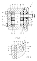
- FIG. 1 a designed as a gear machine 1 hydraulic machine is shown having a machine housing 2, which is closed by means of a bottom plate 4 and a cover plate 6, which are formed as a housing cover.
- the cover plate 6 of the gear machine 1 is penetrated by a drive shaft 8, on which a first gear 10 is disposed within the machine housing 2.
- the first gear 10 is engaged with a second gear 12 which is rotatably mounted on an axle 14.
- the drive shaft 8 and the axis 14 are each rotatably mounted in two plain bearings 16, 18 and 20, 22, which are respectively received in bearing bushes or bearing bodies 24, 26, 28 and 30 respectively.
- the bearing bodies 24 and 28 and the bearing bodies 26 and 30 are connected to each other via a bolt 32 and 34, respectively, and together form a bearing glasses.
- FIG. 2 shows an enlarged section I of the gear machine 1 in the region of the axial field seal 36 from FIG. 1 , where the illustration is rotated 90 ° clockwise.
- the axial field seal 36 has a seal member 38 supported by an L-shaped support member 40.
- the support member 40 has - seen in cross section - while a substantially parallel to the bottom or cover plate 4, 6 from FIG. 1 extending radial leg 42 and one approximately parallel to a rotational axis of the drive shaft 8 from FIG. 1 extending axial leg 44, wherein the sealing element 38 is supported on the one hand on an inner and end edge 46, 48 of the axial leg 44 and on the other at an inner and front edge 50, 51 of the radial leg 42 substantially.
- the sealing and supporting element 38, 40 are in each case in an end face 52 or 53, facing the bottom and cover plate 4, 6, of the respective bearing bodies 24, 28 and 26, 30, see also FIG. 1 , introduced sealing recess or sealing groove 54 added.
- the seal groove 54 is the sliding bearing 16 to 22 (see also FIG. 1 ) and is open in the FIG. 2 bounded by these and by the bottom or top plate 4, 6.
- the support member 40 is inserted into the sealing groove 54, so that a radial outer edge 56 of the radial leg 42, see FIG. 2 at the in FIG. 1 shown cover plate 4 and bottom plate 6 and with an axial outer edge 57 of the axial leg 44 on the slide bearings 16, 20 and 18, 22 approximately abuts.
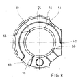
- FIG. 3 is a section taken along the line II-II FIG. 1 shown, with only the bearing body 24 and the sliding bearing 16 are shown in a rotated clockwise by 90 ° view.
- the remaining bearing body 26 to 30 off FIG. 1 are correspondingly mirrored.
- the sealing groove 54 is introduced into the bearing body 24, so that with the Axialfelddichtung 36 from FIG. 1 a high is separated from a low pressure region of the gear machine 1.
- An annular groove portion 60 of the sealing groove 54 extends in sections around the sliding bearing 16 and has a first angled end portion 62, which is towards in the FIG. 1 shown adjacent bearing body 28 extends, and a second angled end portion 64 which extends radially away from the sliding bearing 16 through to in FIG. 1 illustrated machine housing 2 extends.
- Issues to be sealed areas are essentially a bearing gap 66 in the sliding bearing 16 and the respectively formed by the angled end portions 62 and 64 together with the sliding bearing 16 corner regions 68 and 70.
- the seal member 38 see FIG. 2 to avoid between the support member 40 and, for example, the bearing gap 66 or the corner regions 68, 70, the support member 40 in these areas a reduced cross-section, which in the following FIG. 4 is explained in more detail.
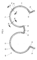
- FIG. 4 the spectacle-shaped support member 40 is shown in a bottom view. There are the radial end and inner edges 48, 50 visible.
- the peripheral shape of the support member 40 and in this FIG. 4 Not shown sealing element 38 substantially corresponds to the shape of the sealing groove 54 FIG. 3 at two juxtaposed bearing bodies 24, 28 and 26, 30 (see FIG. 1 and 3 ).
- Two ring sections 72, 74 of the support member 40 thereby rotate around the plain bearings 16, 20 and 18, 22 (see FIG. 1 and 3 ).
- a connecting bridge 75 connects the Ring portions 72, 74 and each extending between two of the bearing body 24, 28 and 26, 30. End portions 76, 78 bend radially on the ring portions 72, 74 respectively from the slide bearings 16, 20, 18 and 22 to the outside.
- the support element 40 now has several areas with a reduced cross-section for locally reducing the mechanical rigidity and increasing the elasticity. Sections of reduced cross-section are located substantially where the support member 40 is located at problematic areas to be sealed, as in FIG FIG. 3 explained, is present.
- the reduced cross-sectional areas are essentially first crease areas 80, 82 between the ring sections 72 and 74 and the end sections 76 and 78, second crease sections 84, 86 between the connecting web 75 and the ring sections 72, 74 and ring sections 88, 90 approximately at half the length of a stiffener
- the reduced cross-sectional areas 80, 82, 84, 86, 88 and 90 are described in the following FIG. 5a shown in more detail.
- FIG. 5a shows a section along the line III-III and FIG. 5b a section along the line IV-IV respectively from the FIG. 4
- FIG. 5a shows the cross section in the reduced cross-sectional areas 80, 82, 84, 86, 88 and 90.
- the cross section of the axial leg 44 here is approximately trapezoidal and has a reduced cross-sectional area compared to the substantially rectangular cross-section of the axial leg 44 of the FIG.
- the inner edge 46 is in this case angled at an angle e, for example 30 °, which is the intersection angle between outer edge 57 and inner edge 46, so that the front edge 48 of the axial leg 44 is reduced.
- the mechanical stiffness of the axial leg 44 in FIG. 5a thus decreases in the direction of the reduced front edge 48.
- the radial leg 40 in both cross sections in FIGS. 5a and 5b approximately at right angles. To give an indication of the geometric cross - sectional dimensions of the reduced cross section in FIG. 5a in comparison to the unreduced cross section in FIG. 5b to get some values are referred to below.
- the minimum width d1 of the axial leg 40 from FIG. 5a is about 0.2cm and the width d2 of the axial leg 40 from FIG. 5b in about 0.8cm.
- the support member 40 can from the FIG. 4 better in the bearing gaps 66 of the sliding bearing 16 and in the corner regions 68 and 70, respectively FIG. 3 fit and nestle.
- a rearward migration of the support member 40 of the sealing element 38 from FIG. 2 is not or hardly possible anymore.
- the support member 40 is both stiff enough on the one hand to support the hydraulic load and on the other hand flexible enough to close gaps and prevent seal wear.
- a hydraulic gear machine having a housing for receiving two intermeshing and bearing bushes mounted in gears.
- the housing is closed at the front with housing covers.
- a sealing element is provided, which is supported by a support member.
- the support element has sections in the longitudinal direction at least a reduced cross-section for the local reduction of mechanical rigidity.
Landscapes
- Engineering & Computer Science (AREA)
- Mechanical Engineering (AREA)
- General Engineering & Computer Science (AREA)
- Rotary Pumps (AREA)
- General Details Of Gearings (AREA)
- Gear Transmission (AREA)
Abstract
Description
- Die Erfindung betrifft eine hydraulische Zahnradmaschine gemäß dem Oberbegriff des Patentanspruchs 1.
- In der
DE 101 04 621 A1 ist eine Zahnradmaschine mit einem Gehäuse gezeigt, in dem zwei miteinander kämmende und in Lagerbuchsen bzw. Lagerkörpern gelagerte Zahnräder angeordnet sind, wobei das Gehäuse mit Gehäusedeckeln jeweils stirnseitig verschlossen ist. Zur Trennung eines Hoch- und Niederdruckbereichs ist in dem Lagerkörper auf der jeweils dem Gehäusedeckel zugewandten Seite eine Dichtungsnut mit einer darin aufgenommenen Axialfelddichtung ausgebildet. Die Axialfelddichtung weist dabei eine von einem Stützring gestützte elastische Dichtung auf. Der Stützring hat zwei im Wesentlichen L-förmige Stützabschnitte, die über eine Vielzahl von Verbindungsstegen miteinander verbunden sind. Zusammen bilden die L-förmigen Stützabschnitte einen in etwa U-förmigen Querschnitt aus. Die Außenwandungen des Stützrings liegen an dem Gehäusedeckel und an Seitenwandungen der Dichtungsnut in etwa an und die Dichtung ist im Wesentlichen an Innenwandungen des Stützrings abgestützt. Bei Druckbeaufschlagung sind die Dichtung und der Stützring an ihre angrenzenden Dichtflächen, d. h. an den Gehäusedeckel und an Seitenwandungen der Dichtungsnut, gedrückt. - Nachteilig hierbei ist, dass der Stützring eine hohe mechanische Steifigkeit aufweist und somit Unebenheiten oder Spalte beispielsweise im Innenwandungsbereich der Dichtungsnut nur bedingt von dem Stützring ausgeglichen werden können, und die Gefahr besteht, dass die Dichtung bei hohen Drücken zwischen beispielsweise der Innenwandung der Dichtungsnut und der Außenwandung des Stützrings wandert, was zu Beschädigungen und frühen Verschleiß der Dichtung führen kann.
- Eine in der
DE 101 18 055 A1 beschriebene Zahnradmaschine unterscheidet sich im Wesentlichen von der oben erläuterten dadurch, dass der Stützring und das Dichtelement eine andere Ausgestaltung aufweisen. Das Stützelement hat dabei bei einem Ausführungsbeispiel einen U-förmigen und bei einem weiteren einen L-förmigen Querschnitt. Bei dem L-förmigen Stützelement können an einer seitlichen Begrenzungskante und bei dem U-förmigen an beiden seitlichen Begrenzungskanten mehrere Aussparungen über die Längserstreckung des Stützelements regelmäßig verteilt angeordnet sein. Durch die Aussparungen wird die Anlagefläche des Stützelements an die Innenwandungen der Dichtungsnut verkleinert, wodurch die Flächenpressung in diesem Bereich zwischen dem Stützelement und der Innenwandung vergrößert ist. Nachteilig bei dieser Lösung ist ebenfalls, dass das Stützelement im Anlagebereich eine hohe mechanische Steifigkeit aufweist und somit Unebenheiten, Spalte etc. in dem Innenwandungsbereich der Dichtungsnut kaum ausgleichen kann, was zu oben erläuterten Folgeerscheinungen führen kann. - Aufgabe der vorliegenden Erfindung ist es, eine hydraulische Zahnradmaschine zu schaffen, die eine einfach aufgebaute, robuste und eine hohe Dichtwirkung aufweisende Axialfelddichtung hat.
- Diese Aufgabe wird gelöst durch eine hydraulische Zahnradmaschine gemäß den Merkmalen des Patentanspruchs 1.
- Erfindungsgemäß hat eine hydraulische Zahnradmaschine ein Gehäuse zum Aufnehmen zweier miteinander kämmender und in Lagerbuchsen gelagerter Zahnräder. Das Gehäuse ist stirnseitig mit einem Gehäusedeckel verschlossen. Bei der Zahnradmaschine ist dabei ein Dichtungselement vorgesehen, dass von einem als Winkelprofil mit einem Axial- und einen Radialschenkel ausgeführten Stützelement gestützt ist. Zumindest einer der Schenkel hat abschnittsweise in Längserstreckung zumindest einen verminderten Querschnitt zur lokalen Verringerung der mechanischen Steifigkeit.
- Diese Lösung hat den Vorteil, dass das Stützelement in Bereichen, in denen beispielsweise Spalte oder andere dichtungskritische Bereiche auftreten, einen verminderten Querschnitt und somit eine geringere mechanische Steifigkeit aufweist. Hierdurch kann diese sich einfach durch im Wesentlichen elastische Verformungen an die dichtungskritischen Bereiche anpassen. Eine Hinterwanderung des Stützelements durch das Dichtungselement, was im oberen Stand der Technik erläutert ist, wird vermieden.
- Das Stützelement kann vorzugsweise einen im Wesentlichen L-förmigen Querschnitt aufweisen.
- Bei einer vorteilhaften Ausgestaltung ist der verminderte Querschnitt des Stützelements durch eine Anschrägung des Axialschenkels des Stützelements im angrenzenden Bereich zum Dichtungselement ausgebildet. Eine derartige Anschrägung ist zum einen einfach herstellbar und führt zum Anderen zu einer höheren Elastizität des Axialschenkels, durch den verminderten Querschnitt.
- Vorteilhafterweise ist der Axialschenkel des Stützelements im Bereich des verminderten Querschnitts des Stützelements trapezförmig.
- Eine optimale Aufnahme des Dichtungselements und des Stützelements der Zahnradmaschine ist gewährleistet, wenn diese in einer in die Lagerbuchse eingebrachten Dichtungsausnehmung angeordnet sind.
- Zweckmäßig sind zwischen den Lagerbuchsen und den darin gelagerten Zahnrädern Gleitlager vorgesehen. Das Dichtungselement und das Stützelement können dabei in etwa brillenförmig mit jeweils zwei abschnittsweise die Gleitlager umlaufenden Ringabschnitte, mit einem die Ringabschnitte verbindenden Verbindungssteg und mit zwei weg von den Gleitlagern abgewinkelten Endabschnitten ausgebildet sein.
- Mit Vorteil können die verminderten Querschnitte in etwa im Übergangsbereich zwischen Endabschnitten und Ringabschnitten und zwischen Ringabschnitten und etwa auf halber Erstreckungslänge eines jeweiligen Ringabschnitts angeordnet sein, da vor allem in diesen Bereichen beispielsweise Spalte im Dichtungsbereich auftreten.
- Ein fester Sitz des Dichtungselements und des Stützelements ist ermöglicht, wenn das Dichtungselement in etwa an Innenkanten und an Stirnkanten des Stützelements abgestützt ist und das Stützelement mit Außenkanten im Wesentlichen an dem Gehäusedeckel und abschnittsweise an den Gleitlagern in etwa anliegt.
- Vorteilhafterweise ist das Dichtungs- und das Stützelement zwischen einen Niederdruckbereich und einem Hochdruckbereich angeordnet.
- Die Zahnradmaschine kann eine Außenzahnradmaschine sein.
- Sonstige vorteilhafte Weiterbildungen der Erfindung sind Gegenstand weiterer Unteransprüche.
- Im Folgenden wird ein bevorzugtes Ausführungsbeispiel einer Erfindung anhand schematischer Zeichnungen näher erläutert. Es zeigen:
-
Figur 1 eine vereinfachte Darstellung einer Zahnradmaschine im Längsschnitt gemäß einem Ausführungsbeispiel; -
Figur 2 eine vergrößerte Detailansicht gemäß einem Ausschnitt I inFigur 1 ; -
Figur 3 einen Schnitt entlang der Linie II-II inFigur 1 ; -
Figur 4 ein Stützelement in der Untersicht; -
Figur 5a das Stützelement in einer Querschnittansicht entlang der Linie III-III ausFigur 4 ; und -
Figur 5b das Stützelement in einer Querschnittansicht entlang der Linie IV-IV ausFigur 4 . - In
Figur 1 ist eine als Zahnradmaschine 1 ausgebildete hydraulische Arbeitsmaschine dargestellt, die ein Maschinengehäuse 2 aufweist, welches mittels einer Bodenplatte 4 und einer Deckelplatte 6, die als Gehäusedeckel ausgebildet sind, verschlossen ist. Die Deckelplatte 6 der Zahnradmaschine 1 ist von einer Antriebswelle 8 durchgriffen, auf welcher ein erstes Zahnrad 10 innerhalb des Maschinengehäuses 2 angeordnet ist. Das erste Zahnrad 10 steht mit einem zweiten Zahnrad 12 in Eingriff, welches auf einer Achse 14 drehbar angeordnet ist. Die Antriebswelle 8 und die Achse 14 sind jeweils in zwei Gleitlagern 16, 18 bzw. 20, 22 drehbar gelagert, die jeweils in Lagerbuchsen bzw. Lagerkörpern 24, 26, 28 bzw. 30 aufgenommen sind. Die Lagerkörper 24 und 28 sowie die Lagerkörper 26 und 30 sind jeweils über einen Bolzen 32 bzw. 34 miteinander verbunden und bilden jeweils zusammen eine Lagerbrille. - Zwischen der Bodenplatte 4 und den angrenzenden Lagerkörpern 24, 28 und zwischen der Deckelplatte 6 und den an dieser angrenzenden Lagerkörpern 26, 30 ist jeweils eine Axialfelddichtung 36 angeordnet, die in der folgenden Figur näher erläutert ist.
-
Figur 2 zeigt einen vergrößerten Ausschnitt I der Zahnradmaschine 1 im Bereich der Axialfelddichtung 36 ausFigur 1 , wobei die Darstellung um 90 ° im Uhrzeigersinn gedreht ist. Die Axialfelddichtung 36 weist ein Dichtungselement 38 auf, das von einem L-förmigen Stützelement 40 gestützt ist. Das Stützelement 40 hat - im Querschnitt gesehen - dabei einen in etwa parallel zur Boden- bzw. Deckelplatte 4, 6 ausFigur 1 verlaufenden Radialschenkel 42 und einen in etwa parallel zu einer Drehachse der Antriebswelle 8 ausFigur 1 verlaufenden Axialschenkel 44, wobei das Dichtungselement 38 sich zum Einen an einer Innen- und Stirnkante 46, 48 des Axialschenkels 44 und zum Anderen an einer Innen- und Stirnkante 50, 51 des Radialschenkels 42 im Wesentlichen abstützt. - Das Dichtungs- und Stützelement 38, 40 sind jeweils in einer zu der Boden- und Deckelplatte 4, 6 weisenden Stirnfläche 52 bzw. 53 der jeweiligen Lagerkörper 24, 28 bzw. 26, 30, siehe auch
Figur 1 , eingebrachten Dichtungsausnehmung bzw. Dichtungsnut 54 aufgenommen. Die Dichtungsnut 54 ist zum Gleitlager 16 bis 22 (siehe auchFigur 1 ) hin offen und wird in derFigur 2 von diesen und von der Boden- bzw. Deckelplatte 4, 6 begrenzt. Das Stützelement 40 ist dabei derart in die Dichtungsnut 54 eingesetzt, so dass eine radiale Außenkante 56 des Radialschenkels 42, sieheFigur 2 , an der inFigur 1 dargestellten Deckelplatte 4 bzw. Bodenplatte 6 und mit einer axialen Außenkante 57 des Axialschenkels 44 an den Gleitlagern 16, 20 bzw. 18, 22 in etwa anliegt. - In
Figur 3 ist ein Schnitt entlang der Linie II-II ausFigur 1 gezeigt, wobei nur der Lagerkörper 24 und das Gleitlager 16 in einer im Uhrzeigersinn um 90° gedrehten Ansicht dargestellt sind. Die restlichen Lagerkörper 26 bis 30 ausFigur 1 sind entsprechend spiegelverkehrt aufgebaut. Die Dichtungsnut 54 ist derart in den Lagerkörper 24 eingebracht, so dass mit der Axialfelddichtung 36 ausFigur 1 ein Hochvon einem Niederdruckbereich der Zahnradmaschine 1 getrennt ist. Ein Ringnutabschnitt 60 der Dichtungsnut 54 verläuft dabei abschnittsweise um das Gleitlager 16 und hat einen ersten abgewinkelten Endabschnitt 62, der hin zum in derFigur 1 dargestellten benachbarten Lagerkörper 28 verläuft, und einen zweiten abgewinkelten Endabschnitt 64, welcher sich radial weg vom Gleitlager 16 hin bis zum inFigur 1 dargestellten Maschinengehäuse 2 erstreckt. Problematisch zu dichtende Bereiche sind im Wesentlichen ein Lagerspalt 66 im Gleitlager 16 und die durch die abgewinkelten Endabschnitte 62 und 64 zusammen mit dem Gleitlager 16 jeweils gebildeten Eckbereiche 68 bzw. 70. Um ein Eindringen bzw. ein Hinterwandern des Dichtungselements 38, sieheFigur 2 , zwischen dem Stützelement 40 und beispielsweise den Lagerspalt 66 oder den Eckbereichen 68, 70 zu vermeiden, weist das Stützelement 40 in diesen Bereichen einen verminderten Querschnitt auf, was in der folgendenFigur 4 näher erläutert ist. - In
Figur 4 ist das brillenförmige Stützelement 40 in einer Untersicht gezeigt. Es sind dabei die radialen Stirn- und Innenkanten 48, 50 sichtbar. Die Umfangsform des Stützelements 40 und des in dieserFigur 4 nicht dargestellten Dichtungselements 38 (sieheFigur 2 ) entspricht im Wesentlichen der Form der Dichtungsnut 54 ausFigur 3 bei zwei nebeneinander angeordneten Lagerkörpern 24, 28 bzw. 26, 30 (sieheFigur 1 und3 ). Zwei Ringabschnitte 72, 74 des Stützelements 40 umlaufen dabei die Gleitlager 16, 20 bzw. 18, 22 (sieheFigur 1 und3 ). Ein Verbindungssteg 75 verbindet die Ringabschnitte 72, 74 und erstreckt sich jeweils zwischen zwei der Lagerkörper 24, 28 bzw. 26, 30. Endabschnitte 76, 78 knicken radial an den Ringabschnitten 72, 74 jeweils von den Gleitlagern 16, 20, 18 bzw. 22 nach außen weg. - Das Stützelement 40 weist nun mehrere Bereiche mit einem verminderten Querschnitt zur lokalen Verringerung der mechanischen Steifigkeit und Erhöhung der Elastizität auf. Abschnitte mit einem verminderten Querschnitt sind im Wesentlichen dort angeordnet, wo das Stützelement 40 an problematisch zu dichtenden Bereichen, wie in
Figur 3 erläutert, anliegt. Die verminderten Querschnittsbereiche sind im Wesentlichen erste Knickbereiche 80, 82 zwischen den Ringabschnitten 72 und 74 und den Endabschnitten 76 bzw. 78, zweite Knickbereiche 84, 86 zwischen dem Verbindungssteg 75 und den Ringabschnitten 72, 74 und Ringbereiche 88, 90 etwa auf halber Ersteckungslänge eines jeweiligen Ringabschnitts 72, 74. Die verminderten Querschnittsbereiche 80, 82, 84, 86, 88 und 90 werden in der folgendenFigur 5a genauer aufgezeigt. -
Figur 5a zeigt einen Schnitt entlang der Linie III-III undFigur 5b einen Schnitt entlang der Linie IV-IV jeweils aus derFigur 4 . Im Vergleich von derFigur 5a mit derFigur 5b sind die unterschiedlichen Querschnittsformen des Stützelements 40 aus derFigur 4 ersichtlich.Figur 5a zeigt den Querschnitt in den verminderten Querschnittsbereichen 80, 82, 84, 86, 88 und 90. Der Querschnitt des Axialschenkels 44 ist hierbei in etwa trapezförmig ausgebildet und hat eine verminderte Querschnittsfläche gegenüber dem im Wesentlichen rechtwinklig ausgebildeten Querschnitt des Axialschenkels 44 aus derFigur 5b . Die Innenkante 46 ist hierbei mit einem Winkel e, beispielsweise 30°, was der Schnittwinkel zwischen Außenkante 57 und Innenkante 46 ist, angewinkelt, so dass die Stirnkante 48 des Axialschenkels 44 verkleinert ist. Die mechanische Steifigkeit des Axialschenkels 44 inFigur 5a nimmt somit in Richtung der verkleinerten Stirnkante 48 ab. Die Radialschenkel 40 bei beiden Querschnitten inFigur 5a und 5b in etwa rechtwinklig. Um einen Anhaltspunkt für die geometrischen Querschnittsabmessungen des verminderten Querschnitt inFigur 5a im Vergleich zu dem nicht verminderten Querschnitt inFigur 5b zu bekommen, werden im Folgenden einige Werte bezeichnet. Beiden Querschnitten gemeinsam sind die Breite a∼ 0,5mm und die Höhe b∼ 1,3mm des Axialschenkels 40, und die Höhe c∼ 1,6mm des Radialschenkels 44. Die minimale Breite d1 des Axialschenkels 40 ausFigur 5a beträgt in etwa 0,2cm und die Breite d2 des Axialschenkels 40 ausFigur 5b in etwa 0,8cm. - Durch den verminderten Querschnitt und die geringere mechanische Steifigkeit in den Bereichen 80, 82, 84, 86, 88 und 90 kann sich das Stützelement 40 aus der
Figur 4 besser in die Lagerspalte 66 der Gleitlager 16 und in die Eckbereiche 68 bzw. 70 ausFigur 3 einpassen und einschmiegen. Ein Hinterwandern des Stützelements 40 von dem Dichtelement 38 ausFigur 2 ist nicht oder kaum mehr möglich. Das Stützelement 40 ist einerseits insgesamt steif genug, um die hydraulische Last zu tragen und andererseits flexibel genug, um Spalte zu schließen und Dichtungsverschleiß vorzubeugen. - Offenbart ist eine hydraulische Zahnradmaschine, die ein Gehäuse zum Aufnehmen zweier miteinander kämmender und in Lagerbuchsen gelagerter Zahnräder hat. Das Gehäuse ist stirnseitig jeweils mit Gehäusedeckeln verschlossen. Bei der Zahnradmaschine ist dabei ein Dichtungselement vorgesehen, dass von einem Stützelement gestützt ist. Das Stützelement hat abschnittsweise in Längserstreckung zumindest einen verminderten Querschnitt zur lokalen Verringerung der mechanischen Steifigkeit.
Claims (11)
- Hydraulische Zahnradmaschine mit einem Gehäuse (2) zum Aufnehmen zweier miteinander kämmender und in Lagerbuchsen (24, 26, 28, 30) gelagerter Zahnräder (10, 12), das stirnseitig mit einem Gehäusedeckel (4, 6) verschlossen ist, wobei ein Dichtungselement (38) und ein das Dichtungselement (38) stützendes als Winkelprofil mit einem Axialschenkel (44) und einem Radialschenkel (42) ausgeführtes Stützelement (40) vorgesehen sind, dadurch gekennzeichnet, dass zumindest einer der Schenkel (42, 44) abschnittsweise in Längserstreckung zumindest einen verminderten Querschnitt zur lokalen Verringerung der mechanischen Steifigkeit aufweist.
- Hydraulische Zahnradmaschine nach Anspruch 1, wobei das Stützelement (40) einen im Wesentlichen L-förmigen Querschnitt aufweist.
- Hydraulische Zahnradmaschine nach Anspruch 2, wobei der verminderte Querschnitt des Stützelements (40) durch eine Anschrägung des Axialschenkels (44) des Stützelements (40) im angrenzenden Bereich zum Dichtungselement (38) ausgebildet ist.
- Hydraulische Zahnradmaschine nach Anspruch 2 oder 3, wobei der Axialschenkel (44) des Stützelements (40) im Bereich des verminderten Querschnitts des Stützelements (40) trapezförmig ist.
- Hydraulische Zahnradmaschine nach einem der vorhergehenden Ansprüche, wobei das Dichtungselement (38) und das Stützelement (40) in einer in die Lagerbuchse (24, 26, 28, 30) oder in einer in eine zwei Lagerbuchsen (24, 28 bzw. 26, 30) aufweisende Lagerbrille eingebrachte Dichtungsausnehmung (54) angeordnet sind.
- Hydraulische Zahnradmaschine nach einem der vorhergehenden Ansprüche, wobei zwischen den Lagerbuchsen (24, 26, 28, 30) und den darin gelagerten Zahnrädern Gleitlager (16, 18, 20, 22) vorgesehen sind.
- Hydraulische Zahnradmaschine nach Anspruch 6 oder 7, wobei das Dichtungselement (38) und das Stützelement (40) etwa brillenförmig mit jeweils zwei abschnittsweise die Gleitlager (16, 18, 20, 22) umlaufende Ringabschnitte (72, 74), mit einen die Ringabschnitte (72, 74) verbindenden Verbindungssteg (75) und mit zwei weg von den Gleitlagern (16, 18, 20, 22) abgewinkelte Endabschnitte (78, 80) ausgebildet sind.
- Hydraulische Zahnradmaschine nach Anspruch 7, wobei die verminderten Querschnitte in etwa im Übergangsbereich zwischen den Endabschnitten (78, 80) und den Ringabschnitten (72) und zwischen den Ringabschnitten (72, 74) und dem Verbindungssteg (75) und etwa auf halber Erstreckungslänge eines jeweiligen Ringabschnitts (72, 74) angeordnet sind.
- Hydraulische Zahnradmaschine nach einem der Ansprüche 6 bis 8, wobei sich das Dichtungselement (38) in etwa an Innenkanten (46, 50) und an Stirnkanten (48, 51) des Stützelements (40) abstützt und das Stützelement (40) mit Außenkanten (56, 57) im Wesentlichen an dem Gehäusedeckel (4, 6) und abschnittsweise an den Gleitlagern (16, 18, 20, 22) in etwa anliegt.
- Hydraulische Zahnradmaschine nach einem der vorhergehenden Ansprüche, wobei das Dichtungselement (38) und das Stützelement (40) zwischen einem Niederdruckbereich und einem Hochdruckbereich angeordnet sind.
- Hydraulische Zahnradmaschine nach einem der vorhergehenden Ansprüche, wobei die Zahnradmaschine (1) eine Außenzahnradmaschine ist.
Applications Claiming Priority (1)
| Application Number | Priority Date | Filing Date | Title |
|---|---|---|---|
| DE102008038766.5A DE102008038766B4 (de) | 2008-08-12 | 2008-08-12 | Hydraulische Zahnradmaschine |
Publications (3)
| Publication Number | Publication Date |
|---|---|
| EP2154374A2 true EP2154374A2 (de) | 2010-02-17 |
| EP2154374A3 EP2154374A3 (de) | 2014-08-13 |
| EP2154374B1 EP2154374B1 (de) | 2016-03-16 |
Family
ID=41381912
Family Applications (1)
| Application Number | Title | Priority Date | Filing Date |
|---|---|---|---|
| EP09009849.2A Not-in-force EP2154374B1 (de) | 2008-08-12 | 2009-07-30 | Hydraulische Zahnradmaschine |
Country Status (2)
| Country | Link |
|---|---|
| EP (1) | EP2154374B1 (de) |
| DE (1) | DE102008038766B4 (de) |
Cited By (3)
| Publication number | Priority date | Publication date | Assignee | Title |
|---|---|---|---|---|
| DE102013202606A1 (de) | 2013-02-19 | 2014-08-21 | Robert Bosch Gmbh | Zahnradmaschine mit einer Lagerhülse, die mehrere Vorsprünge aufweist. |
| DE102013202918A1 (de) | 2013-02-22 | 2014-08-28 | Robert Bosch Gmbh | Zahnradmaschine mit einem Stützkörper für eine Axialfelddichtung |
| DE102013202917A1 (de) | 2013-02-22 | 2014-08-28 | Robert Bosch Gmbh | Zahnradmaschine mit erhöhter Partikelrobustheit |
Families Citing this family (3)
| Publication number | Priority date | Publication date | Assignee | Title |
|---|---|---|---|---|
| DE102011016810A1 (de) * | 2011-04-12 | 2012-10-18 | Robert Bosch Gmbh | Zahnradwellenanordnung |
| DE102013218758A1 (de) | 2013-09-19 | 2015-03-19 | Robert Bosch Gmbh | Zahnradmaschine mit nicht-zylindrischer Lagerbohrung |
| DE102014212255A1 (de) | 2014-06-26 | 2015-12-31 | Robert Bosch Gmbh | Außenzahnradmaschine mit Lagerkörpern, die geradlinig gleitbeweglich aneinander abgestützt sind |
Citations (2)
| Publication number | Priority date | Publication date | Assignee | Title |
|---|---|---|---|---|
| DE10104621A1 (de) | 2001-02-02 | 2002-08-08 | Bosch Gmbh Robert | Axialfeldabdichtung einer Zahnradmaschine |
| DE10118055A1 (de) | 2001-04-11 | 2002-10-17 | Bosch Gmbh Robert | Hydraulische Arbeitsmaschine |
-
2008
- 2008-08-12 DE DE102008038766.5A patent/DE102008038766B4/de not_active Expired - Fee Related
-
2009
- 2009-07-30 EP EP09009849.2A patent/EP2154374B1/de not_active Not-in-force
Patent Citations (2)
| Publication number | Priority date | Publication date | Assignee | Title |
|---|---|---|---|---|
| DE10104621A1 (de) | 2001-02-02 | 2002-08-08 | Bosch Gmbh Robert | Axialfeldabdichtung einer Zahnradmaschine |
| DE10118055A1 (de) | 2001-04-11 | 2002-10-17 | Bosch Gmbh Robert | Hydraulische Arbeitsmaschine |
Cited By (3)
| Publication number | Priority date | Publication date | Assignee | Title |
|---|---|---|---|---|
| DE102013202606A1 (de) | 2013-02-19 | 2014-08-21 | Robert Bosch Gmbh | Zahnradmaschine mit einer Lagerhülse, die mehrere Vorsprünge aufweist. |
| DE102013202918A1 (de) | 2013-02-22 | 2014-08-28 | Robert Bosch Gmbh | Zahnradmaschine mit einem Stützkörper für eine Axialfelddichtung |
| DE102013202917A1 (de) | 2013-02-22 | 2014-08-28 | Robert Bosch Gmbh | Zahnradmaschine mit erhöhter Partikelrobustheit |
Also Published As
| Publication number | Publication date |
|---|---|
| DE102008038766B4 (de) | 2019-10-10 |
| DE102008038766A1 (de) | 2010-02-18 |
| EP2154374A3 (de) | 2014-08-13 |
| EP2154374B1 (de) | 2016-03-16 |
Similar Documents
| Publication | Publication Date | Title |
|---|---|---|
| EP2154374B1 (de) | Hydraulische Zahnradmaschine | |
| EP0753678B1 (de) | Gleitlager für eine Welle | |
| DE102012103147A1 (de) | Loslager für ein lenkgetriebe | |
| EP3022356B1 (de) | Saug- oder blaswalze mit einer dichtleiste | |
| DE102012207529A1 (de) | Käfigsegment eines Kegelrollenlagers und Kegelrollenlager | |
| DE102012216254A1 (de) | Außenzahnradmaschine | |
| DE602004002828T2 (de) | Zahnradpumpe oder -motor | |
| EP2547925A1 (de) | Gleitlagerschale | |
| DE102004038477B3 (de) | Exzenterschneckenpumpe | |
| EP3568604B1 (de) | Faltenbalg mit mindestens einer innennut | |
| DE102006042190B4 (de) | Rotoreinrichtung einer Pumpe | |
| DE4040426A1 (de) | Abstuetzlager | |
| DE2219829A1 (de) | Zahnradpumpe | |
| DE102008008584A1 (de) | Gleitlagerschale | |
| WO2006077121A1 (de) | Servolenksystem-hydraulikpumpe | |
| DE202012002697U1 (de) | Gleisbaumaschine | |
| EP2647845A2 (de) | Hydrostatische Verdrängermaschine mit gekrümmter Eingriffslinie und Flankenlinienrücknahme | |
| DE102013202917A1 (de) | Zahnradmaschine mit erhöhter Partikelrobustheit | |
| DE10104621B4 (de) | Axialfeldabdichtung einer Zahnradmaschine | |
| DE29810548U1 (de) | Zahnrad für eine Zahnradpumpe | |
| EP3339654B1 (de) | Kreiselpumpe | |
| DE102010060198B4 (de) | Lager für einen Stabilisator eines Kraftfahrzeugs | |
| DE102011013366B4 (de) | Gleitringdichtung | |
| EP2153075A1 (de) | Lager | |
| AT501607B1 (de) | Buchse aus kunststoff |
Legal Events
| Date | Code | Title | Description |
|---|---|---|---|
| PUAI | Public reference made under article 153(3) epc to a published international application that has entered the european phase |
Free format text: ORIGINAL CODE: 0009012 |
|
| AK | Designated contracting states |
Kind code of ref document: A2 Designated state(s): AT BE BG CH CY CZ DE DK EE ES FI FR GB GR HR HU IE IS IT LI LT LU LV MC MK MT NL NO PL PT RO SE SI SK SM TR |
|
| AX | Request for extension of the european patent |
Extension state: AL BA RS |
|
| PUAL | Search report despatched |
Free format text: ORIGINAL CODE: 0009013 |
|
| AK | Designated contracting states |
Kind code of ref document: A3 Designated state(s): AT BE BG CH CY CZ DE DK EE ES FI FR GB GR HR HU IE IS IT LI LT LU LV MC MK MT NL NO PL PT RO SE SI SK SM TR |
|
| AX | Request for extension of the european patent |
Extension state: AL BA RS |
|
| RIC1 | Information provided on ipc code assigned before grant |
Ipc: F04C 15/00 20060101AFI20140708BHEP Ipc: F04C 2/10 20060101ALN20140708BHEP |
|
| 17P | Request for examination filed |
Effective date: 20150213 |
|
| RBV | Designated contracting states (corrected) |
Designated state(s): AT BE BG CH CY CZ DE DK EE ES FI FR GB GR HR HU IE IS IT LI LT LU LV MC MK MT NL NO PL PT RO SE SI SK SM TR |
|
| RIC1 | Information provided on ipc code assigned before grant |
Ipc: F04C 2/10 20060101ALN20150528BHEP Ipc: F04C 15/00 20060101AFI20150528BHEP Ipc: F04C 2/18 20060101ALN20150528BHEP |
|
| GRAP | Despatch of communication of intention to grant a patent |
Free format text: ORIGINAL CODE: EPIDOSNIGR1 |
|
| INTG | Intention to grant announced |
Effective date: 20150703 |
|
| GRAS | Grant fee paid |
Free format text: ORIGINAL CODE: EPIDOSNIGR3 |
|
| GRAA | (expected) grant |
Free format text: ORIGINAL CODE: 0009210 |
|
| AK | Designated contracting states |
Kind code of ref document: B1 Designated state(s): AT BE BG CH CY CZ DE DK EE ES FI FR GB GR HR HU IE IS IT LI LT LU LV MC MK MT NL NO PL PT RO SE SI SK SM TR |
|
| REG | Reference to a national code |
Ref country code: GB Ref legal event code: FG4D Free format text: NOT ENGLISH |
|
| REG | Reference to a national code |
Ref country code: CH Ref legal event code: EP |
|
| REG | Reference to a national code |
Ref country code: IE Ref legal event code: FG4D Free format text: LANGUAGE OF EP DOCUMENT: GERMAN |
|
| REG | Reference to a national code |
Ref country code: AT Ref legal event code: REF Ref document number: 781493 Country of ref document: AT Kind code of ref document: T Effective date: 20160415 |
|
| REG | Reference to a national code |
Ref country code: DE Ref legal event code: R096 Ref document number: 502009012229 Country of ref document: DE |
|
| REG | Reference to a national code |
Ref country code: NL Ref legal event code: MP Effective date: 20160316 |
|
| REG | Reference to a national code |
Ref country code: FR Ref legal event code: PLFP Year of fee payment: 8 |
|
| REG | Reference to a national code |
Ref country code: LT Ref legal event code: MG4D |
|
| PG25 | Lapsed in a contracting state [announced via postgrant information from national office to epo] |
Ref country code: NO Free format text: LAPSE BECAUSE OF FAILURE TO SUBMIT A TRANSLATION OF THE DESCRIPTION OR TO PAY THE FEE WITHIN THE PRESCRIBED TIME-LIMIT Effective date: 20160616 Ref country code: GR Free format text: LAPSE BECAUSE OF FAILURE TO SUBMIT A TRANSLATION OF THE DESCRIPTION OR TO PAY THE FEE WITHIN THE PRESCRIBED TIME-LIMIT Effective date: 20160617 Ref country code: HR Free format text: LAPSE BECAUSE OF FAILURE TO SUBMIT A TRANSLATION OF THE DESCRIPTION OR TO PAY THE FEE WITHIN THE PRESCRIBED TIME-LIMIT Effective date: 20160316 Ref country code: FI Free format text: LAPSE BECAUSE OF FAILURE TO SUBMIT A TRANSLATION OF THE DESCRIPTION OR TO PAY THE FEE WITHIN THE PRESCRIBED TIME-LIMIT Effective date: 20160316 |
|
| PG25 | Lapsed in a contracting state [announced via postgrant information from national office to epo] |
Ref country code: SE Free format text: LAPSE BECAUSE OF FAILURE TO SUBMIT A TRANSLATION OF THE DESCRIPTION OR TO PAY THE FEE WITHIN THE PRESCRIBED TIME-LIMIT Effective date: 20160316 Ref country code: NL Free format text: LAPSE BECAUSE OF FAILURE TO SUBMIT A TRANSLATION OF THE DESCRIPTION OR TO PAY THE FEE WITHIN THE PRESCRIBED TIME-LIMIT Effective date: 20160316 Ref country code: LT Free format text: LAPSE BECAUSE OF FAILURE TO SUBMIT A TRANSLATION OF THE DESCRIPTION OR TO PAY THE FEE WITHIN THE PRESCRIBED TIME-LIMIT Effective date: 20160316 Ref country code: LV Free format text: LAPSE BECAUSE OF FAILURE TO SUBMIT A TRANSLATION OF THE DESCRIPTION OR TO PAY THE FEE WITHIN THE PRESCRIBED TIME-LIMIT Effective date: 20160316 |
|
| PG25 | Lapsed in a contracting state [announced via postgrant information from national office to epo] |
Ref country code: EE Free format text: LAPSE BECAUSE OF FAILURE TO SUBMIT A TRANSLATION OF THE DESCRIPTION OR TO PAY THE FEE WITHIN THE PRESCRIBED TIME-LIMIT Effective date: 20160316 Ref country code: PL Free format text: LAPSE BECAUSE OF FAILURE TO SUBMIT A TRANSLATION OF THE DESCRIPTION OR TO PAY THE FEE WITHIN THE PRESCRIBED TIME-LIMIT Effective date: 20160316 Ref country code: IS Free format text: LAPSE BECAUSE OF FAILURE TO SUBMIT A TRANSLATION OF THE DESCRIPTION OR TO PAY THE FEE WITHIN THE PRESCRIBED TIME-LIMIT Effective date: 20160716 |
|
| PG25 | Lapsed in a contracting state [announced via postgrant information from national office to epo] |
Ref country code: CZ Free format text: LAPSE BECAUSE OF FAILURE TO SUBMIT A TRANSLATION OF THE DESCRIPTION OR TO PAY THE FEE WITHIN THE PRESCRIBED TIME-LIMIT Effective date: 20160316 Ref country code: ES Free format text: LAPSE BECAUSE OF FAILURE TO SUBMIT A TRANSLATION OF THE DESCRIPTION OR TO PAY THE FEE WITHIN THE PRESCRIBED TIME-LIMIT Effective date: 20160316 Ref country code: SM Free format text: LAPSE BECAUSE OF FAILURE TO SUBMIT A TRANSLATION OF THE DESCRIPTION OR TO PAY THE FEE WITHIN THE PRESCRIBED TIME-LIMIT Effective date: 20160316 Ref country code: PT Free format text: LAPSE BECAUSE OF FAILURE TO SUBMIT A TRANSLATION OF THE DESCRIPTION OR TO PAY THE FEE WITHIN THE PRESCRIBED TIME-LIMIT Effective date: 20160718 Ref country code: SK Free format text: LAPSE BECAUSE OF FAILURE TO SUBMIT A TRANSLATION OF THE DESCRIPTION OR TO PAY THE FEE WITHIN THE PRESCRIBED TIME-LIMIT Effective date: 20160316 Ref country code: RO Free format text: LAPSE BECAUSE OF FAILURE TO SUBMIT A TRANSLATION OF THE DESCRIPTION OR TO PAY THE FEE WITHIN THE PRESCRIBED TIME-LIMIT Effective date: 20160316 |
|
| REG | Reference to a national code |
Ref country code: DE Ref legal event code: R097 Ref document number: 502009012229 Country of ref document: DE |
|
| PG25 | Lapsed in a contracting state [announced via postgrant information from national office to epo] |
Ref country code: BE Free format text: LAPSE BECAUSE OF NON-PAYMENT OF DUE FEES Effective date: 20160731 |
|
| PLBE | No opposition filed within time limit |
Free format text: ORIGINAL CODE: 0009261 |
|
| STAA | Information on the status of an ep patent application or granted ep patent |
Free format text: STATUS: NO OPPOSITION FILED WITHIN TIME LIMIT |
|
| PG25 | Lapsed in a contracting state [announced via postgrant information from national office to epo] |
Ref country code: DK Free format text: LAPSE BECAUSE OF FAILURE TO SUBMIT A TRANSLATION OF THE DESCRIPTION OR TO PAY THE FEE WITHIN THE PRESCRIBED TIME-LIMIT Effective date: 20160316 |
|
| 26N | No opposition filed |
Effective date: 20161219 |
|
| PG25 | Lapsed in a contracting state [announced via postgrant information from national office to epo] |
Ref country code: BG Free format text: LAPSE BECAUSE OF FAILURE TO SUBMIT A TRANSLATION OF THE DESCRIPTION OR TO PAY THE FEE WITHIN THE PRESCRIBED TIME-LIMIT Effective date: 20160616 |
|
| REG | Reference to a national code |
Ref country code: CH Ref legal event code: PL |
|
| PG25 | Lapsed in a contracting state [announced via postgrant information from national office to epo] |
Ref country code: MC Free format text: LAPSE BECAUSE OF FAILURE TO SUBMIT A TRANSLATION OF THE DESCRIPTION OR TO PAY THE FEE WITHIN THE PRESCRIBED TIME-LIMIT Effective date: 20160316 |
|
| PG25 | Lapsed in a contracting state [announced via postgrant information from national office to epo] |
Ref country code: CH Free format text: LAPSE BECAUSE OF NON-PAYMENT OF DUE FEES Effective date: 20160731 Ref country code: LI Free format text: LAPSE BECAUSE OF NON-PAYMENT OF DUE FEES Effective date: 20160731 |
|
| REG | Reference to a national code |
Ref country code: IE Ref legal event code: MM4A |
|
| PG25 | Lapsed in a contracting state [announced via postgrant information from national office to epo] |
Ref country code: SI Free format text: LAPSE BECAUSE OF FAILURE TO SUBMIT A TRANSLATION OF THE DESCRIPTION OR TO PAY THE FEE WITHIN THE PRESCRIBED TIME-LIMIT Effective date: 20160316 |
|
| REG | Reference to a national code |
Ref country code: FR Ref legal event code: PLFP Year of fee payment: 9 |
|
| PG25 | Lapsed in a contracting state [announced via postgrant information from national office to epo] |
Ref country code: IE Free format text: LAPSE BECAUSE OF NON-PAYMENT OF DUE FEES Effective date: 20160730 |
|
| PG25 | Lapsed in a contracting state [announced via postgrant information from national office to epo] |
Ref country code: LU Free format text: LAPSE BECAUSE OF NON-PAYMENT OF DUE FEES Effective date: 20160730 |
|
| REG | Reference to a national code |
Ref country code: AT Ref legal event code: MM01 Ref document number: 781493 Country of ref document: AT Kind code of ref document: T Effective date: 20160730 |
|
| PG25 | Lapsed in a contracting state [announced via postgrant information from national office to epo] |
Ref country code: AT Free format text: LAPSE BECAUSE OF NON-PAYMENT OF DUE FEES Effective date: 20160730 |
|
| PG25 | Lapsed in a contracting state [announced via postgrant information from national office to epo] |
Ref country code: HU Free format text: LAPSE BECAUSE OF FAILURE TO SUBMIT A TRANSLATION OF THE DESCRIPTION OR TO PAY THE FEE WITHIN THE PRESCRIBED TIME-LIMIT; INVALID AB INITIO Effective date: 20090730 Ref country code: CY Free format text: LAPSE BECAUSE OF FAILURE TO SUBMIT A TRANSLATION OF THE DESCRIPTION OR TO PAY THE FEE WITHIN THE PRESCRIBED TIME-LIMIT Effective date: 20160316 |
|
| PG25 | Lapsed in a contracting state [announced via postgrant information from national office to epo] |
Ref country code: TR Free format text: LAPSE BECAUSE OF FAILURE TO SUBMIT A TRANSLATION OF THE DESCRIPTION OR TO PAY THE FEE WITHIN THE PRESCRIBED TIME-LIMIT Effective date: 20160316 Ref country code: MK Free format text: LAPSE BECAUSE OF FAILURE TO SUBMIT A TRANSLATION OF THE DESCRIPTION OR TO PAY THE FEE WITHIN THE PRESCRIBED TIME-LIMIT Effective date: 20160316 Ref country code: MT Free format text: LAPSE BECAUSE OF FAILURE TO SUBMIT A TRANSLATION OF THE DESCRIPTION OR TO PAY THE FEE WITHIN THE PRESCRIBED TIME-LIMIT Effective date: 20160316 |
|
| REG | Reference to a national code |
Ref country code: FR Ref legal event code: PLFP Year of fee payment: 10 |
|
| PGFP | Annual fee paid to national office [announced via postgrant information from national office to epo] |
Ref country code: IT Payment date: 20230731 Year of fee payment: 15 Ref country code: GB Payment date: 20230724 Year of fee payment: 15 |
|
| PGFP | Annual fee paid to national office [announced via postgrant information from national office to epo] |
Ref country code: FR Payment date: 20230724 Year of fee payment: 15 Ref country code: DE Payment date: 20230922 Year of fee payment: 15 |
|
| REG | Reference to a national code |
Ref country code: DE Ref legal event code: R119 Ref document number: 502009012229 Country of ref document: DE |
|
| GBPC | Gb: european patent ceased through non-payment of renewal fee |
Effective date: 20240730 |
|
| PG25 | Lapsed in a contracting state [announced via postgrant information from national office to epo] |
Ref country code: DE Free format text: LAPSE BECAUSE OF NON-PAYMENT OF DUE FEES Effective date: 20250201 |
|
| PG25 | Lapsed in a contracting state [announced via postgrant information from national office to epo] |
Ref country code: FR Free format text: LAPSE BECAUSE OF NON-PAYMENT OF DUE FEES Effective date: 20240731 |
|
| PG25 | Lapsed in a contracting state [announced via postgrant information from national office to epo] |
Ref country code: GB Free format text: LAPSE BECAUSE OF NON-PAYMENT OF DUE FEES Effective date: 20240730 |
|
| PG25 | Lapsed in a contracting state [announced via postgrant information from national office to epo] |
Ref country code: IT Free format text: LAPSE BECAUSE OF NON-PAYMENT OF DUE FEES Effective date: 20240730 |