EP2154398A2 - Steuerung für ein Fahrzeug - Google Patents
Steuerung für ein Fahrzeug Download PDFInfo
- Publication number
- EP2154398A2 EP2154398A2 EP09167650A EP09167650A EP2154398A2 EP 2154398 A2 EP2154398 A2 EP 2154398A2 EP 09167650 A EP09167650 A EP 09167650A EP 09167650 A EP09167650 A EP 09167650A EP 2154398 A2 EP2154398 A2 EP 2154398A2
- Authority
- EP
- European Patent Office
- Prior art keywords
- automatic transmission
- torque
- response
- engine
- engagement elements
- Prior art date
- Legal status (The legal status is an assumption and is not a legal conclusion. Google has not performed a legal analysis and makes no representation as to the accuracy of the status listed.)
- Withdrawn
Links
- 230000005540 biological transmission Effects 0.000 claims abstract description 111
- 230000004044 response Effects 0.000 claims abstract description 65
- 230000001133 acceleration Effects 0.000 claims abstract description 9
- 238000012546 transfer Methods 0.000 claims description 21
- 230000007423 decrease Effects 0.000 claims description 13
- 238000000034 method Methods 0.000 claims description 5
- 230000035939 shock Effects 0.000 abstract description 8
- 230000008859 change Effects 0.000 description 52
- 239000000446 fuel Substances 0.000 description 18
- 238000002347 injection Methods 0.000 description 15
- 239000007924 injection Substances 0.000 description 15
- 239000012530 fluid Substances 0.000 description 8
- 238000010586 diagram Methods 0.000 description 7
- 230000006866 deterioration Effects 0.000 description 5
- 230000007935 neutral effect Effects 0.000 description 4
- 239000002826 coolant Substances 0.000 description 3
- 230000003247 decreasing effect Effects 0.000 description 3
- 230000003213 activating effect Effects 0.000 description 1
- 239000000969 carrier Substances 0.000 description 1
- 238000004891 communication Methods 0.000 description 1
- 238000010276 construction Methods 0.000 description 1
- 230000000994 depressogenic effect Effects 0.000 description 1
- 230000006872 improvement Effects 0.000 description 1
- 230000007246 mechanism Effects 0.000 description 1
- 238000012986 modification Methods 0.000 description 1
- 230000004048 modification Effects 0.000 description 1
- 238000012545 processing Methods 0.000 description 1
Images


Classifications
-
- F—MECHANICAL ENGINEERING; LIGHTING; HEATING; WEAPONS; BLASTING
- F16—ENGINEERING ELEMENTS AND UNITS; GENERAL MEASURES FOR PRODUCING AND MAINTAINING EFFECTIVE FUNCTIONING OF MACHINES OR INSTALLATIONS; THERMAL INSULATION IN GENERAL
- F16H—GEARING
- F16H63/00—Control outputs from the control unit to change-speed- or reversing-gearings for conveying rotary motion or to other devices than the final output mechanism
- F16H63/40—Control outputs from the control unit to change-speed- or reversing-gearings for conveying rotary motion or to other devices than the final output mechanism comprising signals other than signals for actuating the final output mechanisms
- F16H63/50—Signals to an engine or motor
- F16H63/502—Signals to an engine or motor for smoothing gear shifts
-
- B—PERFORMING OPERATIONS; TRANSPORTING
- B60—VEHICLES IN GENERAL
- B60W—CONJOINT CONTROL OF VEHICLE SUB-UNITS OF DIFFERENT TYPE OR DIFFERENT FUNCTION; CONTROL SYSTEMS SPECIALLY ADAPTED FOR HYBRID VEHICLES; ROAD VEHICLE DRIVE CONTROL SYSTEMS FOR PURPOSES NOT RELATED TO THE CONTROL OF A PARTICULAR SUB-UNIT
- B60W10/00—Conjoint control of vehicle sub-units of different type or different function
- B60W10/04—Conjoint control of vehicle sub-units of different type or different function including control of propulsion units
- B60W10/06—Conjoint control of vehicle sub-units of different type or different function including control of propulsion units including control of combustion engines
-
- B—PERFORMING OPERATIONS; TRANSPORTING
- B60—VEHICLES IN GENERAL
- B60W—CONJOINT CONTROL OF VEHICLE SUB-UNITS OF DIFFERENT TYPE OR DIFFERENT FUNCTION; CONTROL SYSTEMS SPECIALLY ADAPTED FOR HYBRID VEHICLES; ROAD VEHICLE DRIVE CONTROL SYSTEMS FOR PURPOSES NOT RELATED TO THE CONTROL OF A PARTICULAR SUB-UNIT
- B60W30/00—Purposes of road vehicle drive control systems not related to the control of a particular sub-unit, e.g. of systems using conjoint control of vehicle sub-units
- B60W30/18—Propelling the vehicle
- B60W30/19—Improvement of gear change, e.g. by synchronisation or smoothing gear shift
-
- F—MECHANICAL ENGINEERING; LIGHTING; HEATING; WEAPONS; BLASTING
- F16—ENGINEERING ELEMENTS AND UNITS; GENERAL MEASURES FOR PRODUCING AND MAINTAINING EFFECTIVE FUNCTIONING OF MACHINES OR INSTALLATIONS; THERMAL INSULATION IN GENERAL
- F16H—GEARING
- F16H61/00—Control functions within control units of change-speed- or reversing-gearings for conveying rotary motion ; Control of exclusively fluid gearing, friction gearing, gearings with endless flexible members or other particular types of gearing
- F16H61/04—Smoothing ratio shift
- F16H61/0437—Smoothing ratio shift by using electrical signals
-
- B—PERFORMING OPERATIONS; TRANSPORTING
- B60—VEHICLES IN GENERAL
- B60W—CONJOINT CONTROL OF VEHICLE SUB-UNITS OF DIFFERENT TYPE OR DIFFERENT FUNCTION; CONTROL SYSTEMS SPECIALLY ADAPTED FOR HYBRID VEHICLES; ROAD VEHICLE DRIVE CONTROL SYSTEMS FOR PURPOSES NOT RELATED TO THE CONTROL OF A PARTICULAR SUB-UNIT
- B60W2510/00—Input parameters relating to a particular sub-units
- B60W2510/10—Change speed gearings
- B60W2510/1005—Transmission ratio engaged
-
- F—MECHANICAL ENGINEERING; LIGHTING; HEATING; WEAPONS; BLASTING
- F16—ENGINEERING ELEMENTS AND UNITS; GENERAL MEASURES FOR PRODUCING AND MAINTAINING EFFECTIVE FUNCTIONING OF MACHINES OR INSTALLATIONS; THERMAL INSULATION IN GENERAL
- F16H—GEARING
- F16H2306/00—Shifting
- F16H2306/40—Shifting activities
- F16H2306/42—Changing the input torque to the transmission
-
- F—MECHANICAL ENGINEERING; LIGHTING; HEATING; WEAPONS; BLASTING
- F16—ENGINEERING ELEMENTS AND UNITS; GENERAL MEASURES FOR PRODUCING AND MAINTAINING EFFECTIVE FUNCTIONING OF MACHINES OR INSTALLATIONS; THERMAL INSULATION IN GENERAL
- F16H—GEARING
- F16H61/00—Control functions within control units of change-speed- or reversing-gearings for conveying rotary motion ; Control of exclusively fluid gearing, friction gearing, gearings with endless flexible members or other particular types of gearing
- F16H61/68—Control functions within control units of change-speed- or reversing-gearings for conveying rotary motion ; Control of exclusively fluid gearing, friction gearing, gearings with endless flexible members or other particular types of gearing specially adapted for stepped gearings
- F16H61/684—Control functions within control units of change-speed- or reversing-gearings for conveying rotary motion ; Control of exclusively fluid gearing, friction gearing, gearings with endless flexible members or other particular types of gearing specially adapted for stepped gearings without interruption of drive
- F16H61/686—Control functions within control units of change-speed- or reversing-gearings for conveying rotary motion ; Control of exclusively fluid gearing, friction gearing, gearings with endless flexible members or other particular types of gearing specially adapted for stepped gearings without interruption of drive with orbital gears
Definitions
- the invention relates to a controller for a vehicle that is equipped with a diesel engine and an automatic transmission and, more particularly, to improvement for suppressing deterioration of gear change quality when the automatic transmission changes gears.
- a controller for a vehicle that is equipped with an engine and an automatic transmission is applied to various vehicles.
- the engine is a drive source.
- the automatic transmission changes gears through a plurality of engagement elements of which engagement states are switched by hydraulic control.
- a controller that executes control for suppressing deterioration of gear change quality when an automatic transmission is changing gears As an example of the controller for a vehicle, there is known a controller that executes control for suppressing deterioration of gear change quality when an automatic transmission is changing gears.
- the above controller is described in Japanese Patent Application Publication No. 2005-248728 ( JP-A-2005-248728 ) as a gear change time controller for a vehicle. According to the above technique, when accelerating operation is conducted during clutch-to-clutch gear change of the automatic transmission, an engine torque is controlled in accordance with the progress of gear change.
- a typical diesel engine allows a selected fuel injection amount to be set against the amount of air in a cylinder, so it is known that the response of engine torque to accelerator operation is higher than a petrol engine.
- a diesel engine as a drive source, there is a possibility that hydraulic control of an automatic transmission cannot follow the high response of the diesel engine and, therefore, gear change shock, engine racing, or the like, occurs to deteriorate gear change quality.
- the invention provides a controller for a vehicle, which suppresses deterioration of gear change quality in a vehicle equipped with a diesel engine and an automatic transmission.
- a first aspect of the invention relates to a controller for a vehicle that is equipped with a diesel engine and an automatic transmission that changes gears through a plurality of engagement elements of which engagement states are switched by hydraulic control.
- the controller controls a torque of the diesel engine on the basis of a delay of response of hydraulic control in regard to the engagement elements of the automatic transmission when the torque is varied in response to an acceleration or deceleration request for the vehicle.
- the torque may be controlled on the basis of a predetermined relationship between a delay of response of hydraulic control in regard to the engagement elements of the automatic transmission and a torque of the diesel engine.
- the relationship may be determined so as to slow an increase in torque of the diesel engine in accordance with a delay of response of hydraulic control in regard to the engagement elements of the automatic transmission when the torque is varied to increase.
- the relationship may be determined so as to slow a decrease in torque of the diesel engine in accordance with a delay of response of hydraulic control in regard to the engagement elements of the automatic transmission when the torque is varied to decrease.
- the torque may be controlled on the basis of a transfer function that approximates a response of hydraulic pressures applied to the engagement elements of the automatic transmission.
- the transfer function may linearly approximate a response of hydraulic pressures applied to the engagement elements.
- the transfer function may be a first-order lag function that approximates a response of hydraulic pressures applied to the engagement elements.
- the torque may be controlled not on the basis of a delay of response of hydraulic pressures applied to the engagement elements of the automatic transmission when the automatic transmission is not changing gears.
- a second aspect of the invention relates to a method of controlling a vehicle that is equipped with a diesel engine and an automatic transmission that changes gears through a plurality of engagement elements of which engagement states are switched by hydraulic control.
- the method includes: when the automatic transmission is changing gears, controlling a torque of the diesel engine on the basis of a delay of response of hydraulic control in regard to the engagement elements of the automatic transmission when the torque is changed in response to an acceleration or deceleration request for the vehicle.
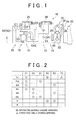
- FIG. 1 is a skeleton diagram of an automatic transmission 10 (hereinafter, simply referred to as automatic transmission 10) for a vehicle according to an embodiment of the invention.
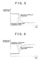
- FIG. 2 is an operation table that illustrates operation states of friction engagement elements, that is, friction engagement devices, when a plurality of gears are selectively established in the automatic transmission 10.
- FIG. 3 is a block diagram that illustrates a relevant portion of a control system provided for a vehicle in order to control the automatic transmission 10 shown in FIG. 1 , and the like, and the schematic configuration of a power train from an engine 30 to drive wheels 46.
- the automatic transmission 10 shown in FIG. 1 is, for example, mounted transversely on an FF vehicle.
- the automatic transmission 10 includes a first gear change unit 14 and a second gear change unit 20 that are arranged along a common axis C in a transmission case 26 (hereinafter, simply referred to as case 26), which serves as a non-rotating member, secured to a vehicle body.
- the first gear change unit 14 is mainly formed of a single pinion type first planetary gear set 12.
- the second gear change unit 20 is mainly formed of a double pinion type second planetary gear set 16 and a single pinion type third planetary gear set 18.
- the automatic transmission 10 is a stepped transmission that changes the rotation of an input shaft 22 in speed and outputs the rotation from an output rotating member 24.
- the input shaft 22 corresponds to an input member.
- the input shaft 22 is a turbine shaft of a torque converter 32, which serves as a hydraulic transmission device that is driven for rotation by the diesel engine 30 (hereinafter, simply referred to as engine 30) that is a power source for propelling the vehicle.
- the output rotating member 24 corresponds to an output member of the automatic transmission 10.
- the output rotating member 24 functions as an output gear, that is, a differential drive gear, that is in mesh with a differential driven gear (large-diameter gear) 42 in order to transmit power to a differential gear unit 40 shown in FIG. 3 .
- the power of the engine 30 is transmitted to the pair of drive wheels 46 via the torque converter 32, the automatic transmission 10, the differential gear unit 40 and a pair of axles 44.
- the automatic transmission 10 and the torque converter 32 each are formed substantially symmetrically with respect to the central axis C shown in FIG. 1 , and the lower half below the central axis C is omitted in the skeleton diagram of FIG. 1 .
- the engine 30 is a swirl chamber diesel engine that compresses and ignites fuel, such as light oil, injected into a swirl chamber (auxiliary chamber) by a fuel injection nozzle 84 shown in FIG. 3 to generate driving force.
- the swirl chamber is in fluid communication with a cylinder.
- a fuel injection controller 86 is provided near the engine 30. The fuel injection controller 86 controls injection of fuel from the fuel injection nozzle 84 in accordance with an instruction from an electronic control unit 90 shown in FIG. 3 .
- the torque converter 32 shown in FIG. 1 includes a lock-up clutch 34 that directly transmits the power of the engine 30 to the input shaft 22 without transmitting the power through fluid.
- the lock-up clutch 34 is a hydraulic friction clutch that is frictionally engaged by a differential pressure ⁇ P between a hydraulic pressure in an engagement-side fluid chamber 36 and a hydraulic pressure in a release-side fluid chamber 38.
- a differential pressure ⁇ P that is, a torque capacity
- the differential pressure ⁇ P is controlled in a feedback manner so that the lock-up clutch 34 is engaged in a predetermined slipped state.
- a turbine shaft (input shaft 22) is rotated to follow the output rotating member (crankshaft) of the engine 30 at a predetermined slip rate, for example, about 50 rpm.
- a hydraulic pump 28 is provided for a pump impeller of the torque converter 32. The hydraulic pump 28 generates a hydraulic pressure used for gear change control or the like of the automatic transmission 10.
- the automatic transmission 10 establishes six forward gears, that is, first gear “1st” to sixth gear “6th”, and reverse gear “R” in accordance with a state where rotating elements (sun gears S1 to S3, carriers CA1 to CA3 and ring gears R1 to R3) of the first gear change unit 14 and second gear change unit 20. As shown in FIG.
- the clutch C1 and the brake B2 are engaged to establish the first gear "1st”
- the clutch C1 and the brake B1 are engaged to establish the second gear "2nd”
- the clutch C1 and the brake B3 are engaged to establish the third gear “3rd”
- the clutch C1 and the clutch C2 are engaged to establish the fourth gear "4th”
- the clutch C2 and the brake B3 are engaged to establish the fifth gear "5th”
- the clutch C2 and the brake B1 are engaged to establish the sixth gear "6th”.
- the brake B2 and the brake B3 are engaged to establish the reverse gear "R”
- all the clutches C1 and C2 and brakes B1 to B3 are released to establish a neutral state.
- the operation table shown in FIG. 2 collectively shows the relationship between the gears and the operation states of the clutches C1 and C2 and brakes B1 to B3.
- the circle represents an engaged state
- the double circle represents an engaged state only during engine braking. Because a one-way clutch F1 (when operated is represented by the triangle in FIG. 2 ) is provided in parallel with the brake B2 that establishes the first gear "1st", only the clutch C1 is engaged at the time of start of running (accelerating), and the clutch C1 and the brake B2 are engaged when engine braking is activated.
- the automatic transmission 10 selectively engages the plurality of engagement devices, that is, the clutches C1 and C2 and the brakes B1, B2 and B3, to establish the plurality of gears having different gear ratios.
- the clutches C1 and C2 and the brakes B1, B2 and B3 are respectively engaged and released (so-called clutch-to-clutch) to thereby make it possible to sequentially change gears.
- clutches C1 and C2 and brakes B1, B2 and B3 are hydraulic friction engagement devices, such as multiple disk clutches or multiple disk brakes, that are controlled for engagement by hydraulic actuators.
- Linear solenoid valves SL1 to SL5 in a hydraulic control circuit 50 are energised or de-energised or controlled in electric current to thereby switch between engage/release states of these clutches C and brakes B while transitional hydraulic pressures, and the like, during release or engagement are controlled.
- the electronic control unit 90 is formed to include a so-called microcomputer provided with a CPU, a RAM, a ROM, an input/output interface, and the like.
- the CPU utilises the temporary storage function of the RAM while handling signal processing in accordance with a programme stored in the ROM beforehand to thereby execute output power control of the engine 30, gear change control of the automatic transmission 10, and on-off control of the lock-up clutch 34.
- the CPU is, where necessary, separated into engine control, gear change control for controlling the linear solenoid valves SL1 to SL5, lock-up clutch control for controlling a linear solenoid valve SLU and a solenoid valve SL of the hydraulic control circuit 50, and the like.
- the electronic control unit 90 includes a storage unit 88 (see FIG. 4 ) for storing various relationships (maps, and the like), which will be described later.
- the accelerator operation amount Acc is an amount of operation of an accelerator pedal 52, which is detected by an accelerator operation amount sensor 54.
- the engine rotational speed NE is a rotational speed of the engine 30, which is detected by an engine rotational speed sensor 56.
- the coolant temperature T W of the engine 30 is detected by a coolant temperature sensor 58.
- the intake air flow rate Q of the engine 30 is detected by an intake air flow rate sensor 60.
- the temperature T A of intake air is detected by an intake air temperature sensor 62.
- the opening degree ⁇ TH of the electronic throttle valve is detected by a throttle valve opening degree sensor 64.
- the rotational speed N OUT of the output rotating member 24, that is, the vehicle speed V is detected by a vehicle speed sensor 66.
- the operation (ON) B ON of the foot brake pedal 68 indicates that a foot brake (wheel brake), which is a service brake, is being operated (being depressed) and is detected by a brake switch 70.
- the lever position P SH of the shift lever 72 is detected by a lever position sensor 74.
- the turbine rotational speed NT is detected by a turbine rotational speed sensor 76.
- the AT fluid temperature T OIL is a temperature of hydraulic fluid in the hydraulic control circuit 50 and is detected by an AT fluid temperature sensor 78.
- the upshift instruction R UP to the gear change range is detected by an upshift switch 80.
- the downshift instruction R DN to the gear change range is detected by a downshift switch 82.
- the electronic control unit 90 outputs a fuel injection amount signal to the fuel injection controller 86.
- the fuel injection amount signal controls an injection amount of fuel (fuel supply amount) injected by the fuel injection nozzle 84 into the swirl chamber of the engine 30.
- the electronic control unit 90 outputs a lever position P SH status signal for activating a shift indicator (not shown), a signal for controlling a shift solenoid that drives a shift valve in the hydraulic control circuit 50 in order to change the gear of the automatic transmission 10, an instruction signal for driving linear solenoid valves that control a line pressure, an instruction signal for driving linear solenoid valves that control engagement, release and slip rate of the lock-up clutch 34, and the like.
- the shift lever 72 is, for example, arranged near the driver's seat, and is manually operated to one of five positions, that is, "P", "R”, “N”, “D” or “S”, as shown in FIG. 3 .
- the "P” position is a parking position at which a power transmission path in the automatic transmission 10 is released, that is, the automatic transmission 10 is placed in a neutral state in which power transmission in the automatic transmission 10 is interrupted, and rotation of the output rotating member 24 is mechanically locked by a mechanical parking mechanism.
- the "R” position is a reverse running position at which the automatic transmission 10 is caused to establish the reverse gear "R” for reverse running mode.
- the "N" position is a neutral position at which the automatic transmission 10 is placed in a neutral state where power transmission in the automatic transmission 10 is interrupted.
- the "D” position is a forward running position at which an automatic gear change mode (D range) is established. In the automatic gear change mode, all the forward gears, that is, the first gear “1st” to sixth gear “6th", within all the gear change range of the automatic transmission 10 are used to carry out gear change control.
- the "S” position is a forward running position at which a sequential mode (hereinafter, referred to as S mode) is established. In the sequential mode, a plurality of types of gear change ranges that respectively limit the ranges in which the forward gears are changed may be manually changed.
- the "S" position is provided with an upshift position "+” for upshifting a gear change range every time the shift lever 72 is operated to the upshift position "+” and a downshift position "-" for downshifting a gear change range every time the shift lever 72 is operated to the downshift position "-".
- Those operations are detected by the upshift switch 80 and the downshift switch 82.
- the shift lever 72 is not stably positioned at the upshift position "+” or the downshift position "-”.
- the shift lever 72 is automatically returned to the "S" position by urging means, such as a spring.
- the gear change range is changed in accordance with the number of times the shift lever 72 is operated to the upshift position "+” or the downshift position "-” or a duration during which the shift lever 72 is held at the upshift position "+” or the downshift position "-".
- the S mode corresponds to a manual gear change mode.
- FIG. 4 is a functional block diagram that illustrates a relevant portion of control functions provided for the electronic control unit 90.
- Gear change control means 92 shown in FIG. 4 controls gear change operation of the automatic transmission 10. That is, the gear change control means 92 determines which gear the automatic transmission 10 should establish from among the above described first gear “1st” to sixth gear “6th” on the basis of the lever position of the shift lever 72 detected by the lever position sensor 74, the operation amount of the accelerator pedal 52 (accelerator operation amount Acc) detected by the accelerator operation amount sensor 54, the vehicle speed V detected by the vehicle speed sensor 66, and the like, by referring to the predetermined relationship (gear change map, or the like) stored in the storage unit 88, or the like. Then, the gear change control means 92 controls the clutches C and the brakes B for engagement or release through the hydraulic control circuit 50 so as to establish the determined gear.
- the gear change control means 92 controls the clutches C and the brakes B for engagement or release through the hydraulic control circuit 50 so as
- Target engine torque calculation means 94 calculates a target engine torque, which is a target value of a torque output from the engine 30. For example, the target engine torque calculation means 94 calculates the target engine torque on the basis of the operation amount of the accelerator pedal 52 (accelerator operation amount Acc) detected by the accelerator operation amount sensor 54, or the like, by referring to the predetermined relationship stored in the storage unit 88.
- Engine torque control means 96 controls a torque output from the engine 30. Specifically, the engine torque control means 96 uses the fuel injection controller 86 to control the injection amount of fuel (fuel supply amount) injected from the fuel injection nozzle 84 into the swirl chamber of the engine 30 on the basis of the target engine torque calculated by the target engine torque calculation means 94, that is, so as to basically achieve the target engine torque, by referring to the predetermined relationship stored in the storage unit 88, thus controlling a torque output from the engine 30.
- fuel injection controller 86 uses the fuel injection controller 86 to control the injection amount of fuel (fuel supply amount) injected from the fuel injection nozzle 84 into the swirl chamber of the engine 30 on the basis of the target engine torque calculated by the target engine torque calculation means 94, that is, so as to basically achieve the target engine torque, by referring to the predetermined relationship stored in the storage unit 88, thus controlling a torque output from the engine 30.
- the engine torque control means 96 controls the torque on the basis of a delay of response of hydraulic control in regard to the engagement elements, that is, the clutches C and brakes B, of the automatic transmission 10 by referring to the predetermined relationship between a delay of response of hydraulic control and an engine torque stored in the storage unit 88.
- the engine torque control means 96 controls the torque of the engine 30 not on the basis of a delay of response of hydraulic pressures applied to the engagement elements of the automatic transmission 10.
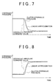
- FIG. 5 is a time chart that shows the relationship between a hydraulic pressure command value output from the electronic control unit 90 and an actual hydraulic pressure (change in hydraulic pressure) in regard to the engagement element that is released when the automatic transmission 10 changes gears.
- FIG. 6 is a time chart that shows the relationship between a hydraulic pressure command value output from the electronic control unit 90 and an actual hydraulic pressure in regard to the engagement element that is engaged when the automatic transmission 10 changes gears.
- the actual hydraulic pressure (change in hydraulic pressure) for releasing or engaging generally varies after a slight delay from a command value output from the electronic control unit 90.
- the actual hydraulic pressure relatively immediately varies following the command value output from the electronic control unit 90.
- the engine torque control means 96 increases the torque of the engine 30 in response to an acceleration request for the vehicle
- the engine torque control means 96 slows an increase in the torque (rate of increase per unit time) as compared with that during normal states in accordance with a delay of response of hydraulic control in regard to the engagement elements of the automatic transmission 10.
- the relationship stored in the storage unit 88 for controlling the torque of the engine 30 is determined so as to slow an increase in the torque of the engine 30 in accordance with a delay of response of hydraulic control in regard to the engagement elements of the automatic transmission 10 when the torque is varied to increase.
- the engine torque control means 96 decreases the torque of the engine 30 in accordance with a deceleration request for the vehicle
- the engine torque control means 96 slows a decrease in the torque (rate of decrease per unit time) in accordance with a delay of response of hydraulic control in regard to the engagement elements of the automatic transmission 10.
- the relationship stored in the storage unit 88 for controlling the torque of the engine 30 is determined so as to slow a decrease in the torque of the engine 30 in accordance with a delay of response of hydraulic control in regard to the engagement elements of the automatic transmission 10 when the torque is varied to decrease.
- the engine torque control means 96 approximates the response of hydraulic pressures applied to the engagement elements of the automatic transmission 10 to a transfer function, and then controls the torque of the engine 30 on the basis of the transfer function.
- the relationship stored in the storage unit 88 for controlling the torque of the engine 30 is determined on the basis of the transfer function that approximates the response of hydraulic pressures applied to the engagement elements of the automatic transmission 10.
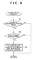
- FIG. 7 is a view that shows a transfer function that linearly approximates the response of a hydraulic pressure, shown in FIG. 5 , applied to the engagement element that is released when the automatic transmission 10 changes gears.
- the engine torque control means 96 executes the target engine torque control on the basis of the transfer function shown in FIG. 7 when the target engine torque is decreased. For example, a rate of change (a rate of change over time) at which an engine torque at that time shifts to the target engine torque is controlled on the basis of the transfer function shown in FIG. 7 .
- FIG. 8 is a view that shows a transfer function that linearly approximates the response of a hydraulic pressure, shown in FIG. 6 , applied to the engagement element that is engaged when the automatic transmission 10 changes gears.
- the engine torque control means 96 executes the target engine torque control on the basis of the transfer function shown in FIG. 8 when the target engine torque is increased. For example, a rate of change (a rate of change over time) at which an engine torque at that time becomes the target engine torque is controlled on the basis of the transfer function shown in FIG. 8 .
- FIG. 9 is a flowchart that illustrates a relevant portion of engine torque control executed by the electronic control unit 90. The flowchart is repeatedly executed at predetermined time intervals.
- step (hereinafter, "step” is omitted) S1 the electronic control unit 90 determines whether the automatic transmission 10 is changing gears. When a negative determination is made in S1, the routine ends accordingly. When an affirmative determination is made in S1, it is determined in S2 whether a target engine torque is varied because of a variation in the operation amount of the accelerator pedal 52, or the like.
- the controller controls the torque on the basis of a delay of response of hydraulic control in regard to the engagement elements of the automatic transmission 10 by referring to the predetermined relationship.
- the relationship between a delay of response of hydraulic control and an engine torque is determined so as to slow an increase in the torque of the diesel engine 30 in accordance with a delay of response of hydraulic control in regard to the engagement elements of the automatic transmission 10 when the torque increases.
- the relationship between a delay of response of hydraulic control and an engine torque is determined so as to slow a decrease in the torque of the diesel engine 30 in response to a delay of response of hydraulic control in regard to the engagement elements of the automatic transmission 10 when the torque decreases.
- the torque of the diesel engine 30 is controlled not on the basis of a delay of response of hydraulic pressures applied to the engagement elements of the automatic transmission 10.
- the response of the diesel engine 30 is not decreased intentionally to make it possible to obtain the original response.
- the engine torque control means 96 controls the torque of the engine 30 on the basis of the transfer function that linearly approximates the response of hydraulic pressures applied to the engagement elements that are engaged or released when the automatic transmission 10 changes gears; however, the aspect of the invention is not limited to this configuration.
- the torque of the engine 30 may be controlled on the basis of a first-order lag function, as a transfer function, that approximates the response of hydraulic pressures applied to the engagement elements that are released or engaged when the automatic transmission 10 changes gears.
Landscapes
- Engineering & Computer Science (AREA)
- General Engineering & Computer Science (AREA)
- Mechanical Engineering (AREA)
- Chemical & Material Sciences (AREA)
- Combustion & Propulsion (AREA)
- Transportation (AREA)
- Automation & Control Theory (AREA)
- Control Of Vehicle Engines Or Engines For Specific Uses (AREA)
- Control Of Transmission Device (AREA)
Applications Claiming Priority (1)
| Application Number | Priority Date | Filing Date | Title |
|---|---|---|---|
| JP2008207311A JP2010043584A (ja) | 2008-08-11 | 2008-08-11 | 車両の制御装置 |
Publications (1)
| Publication Number | Publication Date |
|---|---|
| EP2154398A2 true EP2154398A2 (de) | 2010-02-17 |
Family
ID=41259494
Family Applications (1)
| Application Number | Title | Priority Date | Filing Date |
|---|---|---|---|
| EP09167650A Withdrawn EP2154398A2 (de) | 2008-08-11 | 2009-08-11 | Steuerung für ein Fahrzeug |
Country Status (2)
| Country | Link |
|---|---|
| EP (1) | EP2154398A2 (de) |
| JP (1) | JP2010043584A (de) |
Cited By (2)
| Publication number | Priority date | Publication date | Assignee | Title |
|---|---|---|---|---|
| CN112109714A (zh) * | 2020-09-28 | 2020-12-22 | 北京车和家信息技术有限公司 | 车辆前进档切换空档的扭矩控制方法、装置及车辆 |
| CN115234644A (zh) * | 2022-08-04 | 2022-10-25 | 潍柴动力股份有限公司 | 一种车辆自动变速箱的档位控制方法及装置 |
Citations (1)
| Publication number | Priority date | Publication date | Assignee | Title |
|---|---|---|---|---|
| JP2005248728A (ja) | 2004-03-01 | 2005-09-15 | Toyota Motor Corp | 車両の変速時制御装置 |
Family Cites Families (2)
| Publication number | Priority date | Publication date | Assignee | Title |
|---|---|---|---|---|
| JP2000272380A (ja) * | 1999-03-24 | 2000-10-03 | Mitsubishi Motors Corp | 車両用制御装置 |
| JP2003184594A (ja) * | 2001-12-18 | 2003-07-03 | Mitsubishi Motors Corp | エンジンと自動変速機との統合制御装置 |
-
2008
- 2008-08-11 JP JP2008207311A patent/JP2010043584A/ja active Pending
-
2009
- 2009-08-11 EP EP09167650A patent/EP2154398A2/de not_active Withdrawn
Patent Citations (1)
| Publication number | Priority date | Publication date | Assignee | Title |
|---|---|---|---|---|
| JP2005248728A (ja) | 2004-03-01 | 2005-09-15 | Toyota Motor Corp | 車両の変速時制御装置 |
Cited By (2)
| Publication number | Priority date | Publication date | Assignee | Title |
|---|---|---|---|---|
| CN112109714A (zh) * | 2020-09-28 | 2020-12-22 | 北京车和家信息技术有限公司 | 车辆前进档切换空档的扭矩控制方法、装置及车辆 |
| CN115234644A (zh) * | 2022-08-04 | 2022-10-25 | 潍柴动力股份有限公司 | 一种车辆自动变速箱的档位控制方法及装置 |
Also Published As
| Publication number | Publication date |
|---|---|
| JP2010043584A (ja) | 2010-02-25 |
Similar Documents
| Publication | Publication Date | Title |
|---|---|---|
| US8366587B2 (en) | Control device of vehicle drive-train system | |
| US9014927B2 (en) | Shift control system and shift control method | |
| US7462130B2 (en) | Control apparatus and control method of an automatic transmission | |
| US20180065618A1 (en) | Control device and control method for vehicle | |
| JP5983857B2 (ja) | 変速機の制御装置および制御方法 | |
| US8392076B2 (en) | Control device of vehicular automatic transmission | |
| US7740559B2 (en) | Shift control device of vehicular automatic transmission | |
| US7625313B2 (en) | Shift control device and shift control method of vehicular automatic transmission | |
| JP4639760B2 (ja) | 自動変速機の変速制御装置 | |
| US7578760B2 (en) | Automatic transmission controller for a vehicle and method for controlling an automatic transmission system for a vehicle | |
| JP2011202776A (ja) | 車両用ロックアップクラッチの制御装置 | |
| US9096217B2 (en) | Control apparatus for transmission, and control method for transmission | |
| JP2012211634A (ja) | 自動変速装置および変速機の変速段の異常判定方法 | |
| US7563198B2 (en) | Shift control device and shift control method of automatic transmission | |
| CN100439766C (zh) | 自动变速器的管线压力控制装置和管线压力控制方法 | |
| EP2123944B1 (de) | Schaltungssteuerung für Fahrzeugautomatikgetriebe | |
| CN100470098C (zh) | 车辆自动变速器的变速控制装置和变速控制方法 | |
| JP4240048B2 (ja) | 車両用自動変速機の変速制御装置 | |
| JP6520804B2 (ja) | 車両用自動変速機の制御装置 | |
| JP2010043584A (ja) | 車両の制御装置 | |
| JP4114432B2 (ja) | 車両用自動変速機の油圧制御装置 | |
| JP2004060733A (ja) | 車両用自動変速機の制御装置 | |
| JP2008144737A (ja) | 動力出力装置の制御装置 | |
| JP2009180340A (ja) | 自動変速機の制御装置、制御方法およびその方法をコンピュータで実現されるプログラムならびにそのプログラムを記録した記録媒体 | |
| JP2010175060A (ja) | 車両の制御装置 |
Legal Events
| Date | Code | Title | Description |
|---|---|---|---|
| PUAI | Public reference made under article 153(3) epc to a published international application that has entered the european phase |
Free format text: ORIGINAL CODE: 0009012 |
|
| 17P | Request for examination filed |
Effective date: 20090827 |
|
| AK | Designated contracting states |
Kind code of ref document: A2 Designated state(s): AT BE BG CH CY CZ DE DK EE ES FI FR GB GR HR HU IE IS IT LI LT LU LV MC MK MT NL NO PL PT RO SE SI SK SM TR |
|
| AX | Request for extension of the european patent |
Extension state: AL BA RS |
|
| STAA | Information on the status of an ep patent application or granted ep patent |
Free format text: STATUS: THE APPLICATION HAS BEEN WITHDRAWN |
|
| 18W | Application withdrawn |
Effective date: 20110407 |