EP2154465A2 - Plattenwärmetauscher - Google Patents
Plattenwärmetauscher Download PDFInfo
- Publication number
- EP2154465A2 EP2154465A2 EP09167062A EP09167062A EP2154465A2 EP 2154465 A2 EP2154465 A2 EP 2154465A2 EP 09167062 A EP09167062 A EP 09167062A EP 09167062 A EP09167062 A EP 09167062A EP 2154465 A2 EP2154465 A2 EP 2154465A2
- Authority
- EP
- European Patent Office
- Prior art keywords
- plate
- heat exchanger
- connection
- plate heat
- plates
- Prior art date
- Legal status (The legal status is an assumption and is not a legal conclusion. Google has not performed a legal analysis and makes no representation as to the accuracy of the status listed.)
- Granted
Links
Images




Classifications
-
- F—MECHANICAL ENGINEERING; LIGHTING; HEATING; WEAPONS; BLASTING
- F28—HEAT EXCHANGE IN GENERAL
- F28F—DETAILS OF HEAT-EXCHANGE AND HEAT-TRANSFER APPARATUS, OF GENERAL APPLICATION
- F28F9/00—Casings; Header boxes; Auxiliary supports for elements; Auxiliary members within casings
- F28F9/02—Header boxes; End plates
- F28F9/0246—Arrangements for connecting header boxes with flow lines
- F28F9/0251—Massive connectors, e.g. blocks; Plate-like connectors
-
- F—MECHANICAL ENGINEERING; LIGHTING; HEATING; WEAPONS; BLASTING
- F28—HEAT EXCHANGE IN GENERAL
- F28D—HEAT-EXCHANGE APPARATUS, NOT PROVIDED FOR IN ANOTHER SUBCLASS, IN WHICH THE HEAT-EXCHANGE MEDIA DO NOT COME INTO DIRECT CONTACT
- F28D9/00—Heat-exchange apparatus having stationary plate-like or laminated conduit assemblies for both heat-exchange media, the media being in contact with different sides of a conduit wall
- F28D9/0031—Heat-exchange apparatus having stationary plate-like or laminated conduit assemblies for both heat-exchange media, the media being in contact with different sides of a conduit wall the conduits for one heat-exchange medium being formed by paired plates touching each other
- F28D9/0043—Heat-exchange apparatus having stationary plate-like or laminated conduit assemblies for both heat-exchange media, the media being in contact with different sides of a conduit wall the conduits for one heat-exchange medium being formed by paired plates touching each other the plates having openings therein for circulation of at least one heat-exchange medium from one conduit to another
- F28D9/005—Heat-exchange apparatus having stationary plate-like or laminated conduit assemblies for both heat-exchange media, the media being in contact with different sides of a conduit wall the conduits for one heat-exchange medium being formed by paired plates touching each other the plates having openings therein for circulation of at least one heat-exchange medium from one conduit to another the plates having openings therein for both heat-exchange media
-
- F—MECHANICAL ENGINEERING; LIGHTING; HEATING; WEAPONS; BLASTING
- F28—HEAT EXCHANGE IN GENERAL
- F28F—DETAILS OF HEAT-EXCHANGE AND HEAT-TRANSFER APPARATUS, OF GENERAL APPLICATION
- F28F9/00—Casings; Header boxes; Auxiliary supports for elements; Auxiliary members within casings
- F28F9/007—Auxiliary supports for elements
- F28F9/0075—Supports for plates or plate assemblies
-
- F—MECHANICAL ENGINEERING; LIGHTING; HEATING; WEAPONS; BLASTING
- F28—HEAT EXCHANGE IN GENERAL
- F28D—HEAT-EXCHANGE APPARATUS, NOT PROVIDED FOR IN ANOTHER SUBCLASS, IN WHICH THE HEAT-EXCHANGE MEDIA DO NOT COME INTO DIRECT CONTACT
- F28D21/00—Heat-exchange apparatus not covered by any of the groups F28D1/00 - F28D20/00
- F28D2021/0019—Other heat exchangers for particular applications; Heat exchange systems not otherwise provided for
- F28D2021/008—Other heat exchangers for particular applications; Heat exchange systems not otherwise provided for for vehicles
- F28D2021/0089—Oil coolers
-
- F—MECHANICAL ENGINEERING; LIGHTING; HEATING; WEAPONS; BLASTING
- F28—HEAT EXCHANGE IN GENERAL
- F28F—DETAILS OF HEAT-EXCHANGE AND HEAT-TRANSFER APPARATUS, OF GENERAL APPLICATION
- F28F2280/00—Mounting arrangements; Arrangements for facilitating assembling or disassembling of heat exchanger parts
- F28F2280/06—Adapter frames, e.g. for mounting heat exchanger cores on other structure and for allowing fluidic connections
Definitions
- the invention relates to a plate heat exchanger having a plurality of stacked parallel trough-like plates, the flow spaces for at least two media, with a connection element for receiving at least one nozzle in the region of a preferably trough-like end plate, wherein the nozzle on a protruding with respect to the plates section of the connection element is arranged
- the EP 0 604 193 B1 describes an oil cooler without housing, which is designed as a plate heat exchanger.
- the plate heat exchanger has a number of trough-like plates arranged parallel to one another, between which flow spaces for two different media are alternately spanned.
- the plate heat exchanger is closed by an end plate and a connecting element with side ports upwards.
- the DE 10 2006 029 110 A1 describes a heat exchanger with a heat exchanger jacket and disposed within the heat exchanger jacket plate packs, wherein the plate pack has at least one tubular connecting piece, which is performed by a passage in the heat exchanger jacket.
- a connection element is provided with an annular base body which can be screwed or inserted into the shell, wherein the pipe socket is spaced from the base body with an annular gap.
- a Tüllenelement is arranged on an outer side of the base body, which has a Tüllenwandung, which is formed in cross-section approximately S-shaped and extending away from the jacket.
- the spout is located in the region of a free circumferential edge closely adjacent to the pipe socket or is located on this and is attached with a weld on the neck.
- the DE 197 27 145 A1 describes a housing-less plate heat exchanger having a plurality of deformed, nested and a packet-forming heat exchanger plates having separate flow channels for heat exchanging media, wherein in the region of a protruding portion of a connecting element radially exiting ports for the supply and discharge of at least one medium is arranged.
- a plate heat exchanger with a stack of heat exchanger plates which has a top end of the stack cover plate which communicates with an inlet and outlet channel and which has an inlet cross-section and an outlet cross-section and serves to connect an inlet and outlet line.
- a shellless plate heat exchanger which has stacked heat exchanger plates, wherein the stack of heat exchanger plates is limited by a base plate and an end plate. Base plate and end plate have connections for the heat exchange media.
- the object of the invention is to avoid these disadvantages and to avoid structural constraints on a production moderately simple way.
- connecting lines can be guided laterally of the plate heat exchanger. This allows great design freedom in the choice of installation situation, as in the direction of the vertical axis much less space is required.
- connection element consists of a connection plate and a fixed attached to the connection plate patch channel part, wherein the channel part can be formed as a preferably formed sheet metal or forged part or as a casting.
- the channel portion may be connected to the terminal plate by a solder, glue, screw or flare connection.
- the channel part is formed by a channel plate with at least one molded flow channel, which is preferably completed by a cover plate is particularly advantageous. This allows a particularly flat design of the connection element.
- the terminal plate is formed by the end plate.
- the terminal plate is formed integrally with the end plate, the number of parts can be limited.
- connection plate is firmly connected to the end plate.
- the terminal plate may be connected to the end plate by soldering, gluing, screwing or the like.
- a further saving in components results when the nozzle is formed integrally with the channel part.
- the protruding portion of the connecting element is angled with respect to the end plate, wherein preferably a joining plane with the plane of the end plate has an angle between 0 ° and 90 °, preferably between 20 ° and 40 °.
- connection plate may be stepped in the region of the protruding section, wherein preferably the connection plate is spaced from a connection plane of the end plate in the region of the protruding section.
- the plate heat exchangers 1 shown in the figures each have a stack 2 spaced plates 3, which alternately span a first and a second flow space, which are flowed through by a first and second medium.
- the plate stack 2 is bounded by a bottom plate 4 and an end plate 5. All plates 3, 4, 5 are connected by a soldering process.
- connection element 6 In the region of the end plate 5, a connecting element 6 is arranged, which has a theoryorkragenden section 7 with a nozzle 13 with respect to the plates 3, 4, 5.
- the connection element 6 has a connection plate 8.
- a channel part 9 is fixed to the flat connection plate 8, which may be formed as a deep-drawn or stamped and punched sheet metal part or as a forged part.
- the channel part 9 is fixedly connected to the connection plate 8, for example, by a solder connection, a screw connection, an adhesive connection or a crimp connection.
- connection plate 8 and the channel part 9 Between the connection plate 8 and the channel part 9, a flow channel 10 is formed, which on the one hand via a passage opening not shown in the connection plate 8 and the end plate 5 with the flow spaces in the plate heat exchanger 1 and on the other hand via a passage opening 11 in the connection plate 8 or in the channel part. 9 , in which the nozzle 13 is inserted, is connected to not shown connecting lines.
- the nozzle 13 is arranged on the stack 2 of plates 3 facing first side 12 of the connection plate 8.
- the connecting element 6 is angled in relation to the end plate 5 in the region of the protruding portion 7, wherein a dividing plane 14 between the connecting plate 8 and the channel part 9 with the plane 5a of the end plate 5 an angle ⁇ between 0 ° and 90 °, in the embodiment about 30 °, includes.
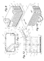
- FIG. 9 to FIG. 12 Illustrated embodiment differs from the embodiment according to Fig. 6 to Fig. 8 essentially in that the connecting piece 13 is formed by a connection block.
- the connecting element 6 is stepped, wherein the protruding portion 7 of the connection plate 8 is spaced from the connection plane 5a of the end plate 5 clearly in the direction of the bottom plate 4.
- the corresponding distance is in Fig. 16 denoted by a.
- This embodiment is particularly suitable for plate heat exchanger 1 with trough-like plates 3, whose edges 3a are directed to the bottom plate 4.
- the bottom plate 8 is integrally formed from the end plate 5, whereby compared to de embodiments after Fig. 1 to Fig. 12 a component is saved.
- FIGS. 17 to 20 show a further embodiment variant with a stepped running connection element 6, wherein the connection plate 8 is further spaced in the region of the protruding portion 7 of the bottom plate 4 by the distance a, as the connection plane 5a of the end plate 5.
- This allows the projection according to the invention also in Heat exchangers whose edges 3a are directed away from the bottom plate 4.
- FIG. 20a another embodiment is shown, different from the one in FIGS. 17 to 20 shown embodiment differs only in that the connection plate is made in one piece with the end plate 5, whereby a component is eliminated.
- FIG. 1 to Fig. 20 Embodiments are shown in which the channel part 6 is connected via a flange-shaped connection with the connection plate 8.
- the 21 to FIG. 24 show an embodiment in which the connection between the channel part 6 and the connection plate 8 via a blunt T-joint. This design has the advantage that width can be saved.
- the channel part 9 is formed by a substantially flat channel plate 16, in which flow channels 10, 10 a are formed, wherein the flow channels 10, 10 a closed by an attached cover plate 15 upwards.
- the flow channels 10, 10 a lead to passage openings 11, 11 a with a connection 13.
- the seal between the channel part 9 and the connection plate 8 can be done in the case of a screw or Börtelharm by an example permanently elastic seal.
Landscapes
- Engineering & Computer Science (AREA)
- Physics & Mathematics (AREA)
- Thermal Sciences (AREA)
- Mechanical Engineering (AREA)
- General Engineering & Computer Science (AREA)
- Heat-Exchange Devices With Radiators And Conduit Assemblies (AREA)
Abstract
Description
- Die Erfindung betrifft einen Plattenwärmetauscher mit einer Vielzahl von übereinander gestapelten parallelen wannenartigen Platten, die Durchflussräume für zumindest zwei Medien aufspannen, mit einem Anschlusselement zur Aufnahme zumindest eines Stutzens im Bereich einer vorzugsweise wannenartigen Endplatte, wobei der Stutzen an einem in Bezug auf die Platten hervorkragenden Abschnitt des Anschlusselementes angeordnet ist
- Die
EP 0 604 193 B1 beschreibt einen Ölkühler ohne Gehäuse, welcher als Plattenwärmetauscher konzipiert ist. Der Plattenwärmetauscher weist eine Anzahl an parallel zueinander angeordneten wannenartigen Platten auf, zwischen welchen abwechselnd Durchflussräume für zwei verschiedene Medien aufgespannt werden. Der Plattenwärmetauscher wird durch eine Endplatte und ein Anschlusselement mit seitlichen Stutzen nach oben abgeschlossen. - Weiters ist aus der
DE 10 2005 050 738 A1 ein Wärmetauscher in Plattenbauweise mit Anschlussstutzen bekannt, welche in Öffnungen der Endplatte eingesetzt werden. Das Einsetzen erfolgt üblicherweise durch Verpressen, Nieten, Punktschweißen oder ähnlichem Zwischenschritt. Dadurch wird der solcher Art fixierte Anschlussstutzen dauerhaft mit der Abdeckplatte verlötet. - Die
DE 10 2006 029 110 A1 beschreibt einen Wärmetauscher mit einem Wärmetauschermantel und innerhalb des Wärmetauschermantels angeordneten Plattenpaketen, wobei das Plattenpaket zumindest einen rohrförmigen Anschlussstutzen aufweist, der durch eine Durchführung im Wärmetauschermantel durchgeführt ist. Dabei ist ein Anschlusselement mit einem ringartigen Grundkörper vorgesehen, der in den Mantel einschraub- oder einsteckbar ist, wobei der Rohrstutzen vom Grundkörper mit einem Ringspalt beabstandet ist. Weiters ist an einer Außenseite des Grundkörpers ein Tüllenelement angeordnet, welches eine Tüllenwandung besitzt, die im Querschnitt in etwa S-förmig ausgebildet ist und sich vom Mantel weg erstreckt. Die Tülle ist im Bereich einer freien umlaufenden Kante dicht benachbart zum Rohrstutzen angeordnet oder liegt an diesem an und ist mit einer Schweißnaht am Stutzen befestigt. - Die
DE 197 27 145 A1 beschreibt einen gehäuselosen Plattenwärmetauscher mit einer Vielzahl verformter, ineinander gestapelter und ein Paket bildender Wärmetauscherplatten, die getrennte Strömungskanäle für wärmeaustauschende Medien aufweisen, wobei im Bereich eines hervorkragenden Abschnittes eines Anschlusselementes radial austretende Anschlüsse für die Zu- und Abführung zumindest eines Mediums angeordnet ist. - Aus der
DE 103 04 733 A1 ist ein Plattenwärmetauscher mit einem Stapel aus Wärmetauscherplatten bekannt, welcher eine den Stapel nach oben abschließende Deckplatte aufweist, der mit einem Eintritts- bzw. Austrittskanal kommuniziert und der einen Eintrittsquerschnitt und einen Austrittsquerschnitt aufweist und zum Anschluss einer Zu- bzw. Abführleitung dient. - Aus der
DE 198 02 012 A1 ist ein gehäuseloser Plattenwärmetauscher bekannt, welcher übereinander gestapelte Wärmetauscherplatten aufweist, wobei der Stapel von Wärmetauscherplatten durch eine Grundplatte und eine Endplatte begrenzt wird. Grundplatte und Endplatte weisen Anschlüsse für die Wärmetauschermedien auf. - Die Stutzenanbindungen an die Abdeckplatten von bekannten Wärmetauschern haben den Nachteil eines relativ hohen Fertigungsaufwandes. Ein weiterer Nachteil ist, dass wegen der Anordnung der Stutzen an der Oberseite bauliche Zwänge in der Einbausituation entstehen.
- Aufgabe der Erfindung ist es, diese Nachteile zu vermeiden und auf eine herstellungsmäßig einfache Weise bauliche Zwänge zu vermeiden.
- Erfindungsgemäß wird dies dadurch erreicht, dass der Stutzen auf der den Platten zugewandten Seite des Anschlusselementes, vorzugsweise an der Anschlussplatte im Bereich einer Durchtrittsöffnung befestigt ist.
- Dadurch, dass der Stutzen an einem hervorkragenden Abschnitt des Anschlusselementes angeordnet ist, können Anschlussleitungen seitlich des Plattenwärmetauschers geführt werden. Dies ermöglicht große konstruktive Freiheiten bei der Wahl der Einbausituation, da in Richtung der Hochachse wesentlich weniger Bauraum erforderlich ist.
- Vorzugsweise ist vorgesehen, dass das Anschlusselement aus einer Anschlussplatte und einem mit der Anschlussplatte fest verbundenen aufgesetzten Kanalteil besteht, wobei der Kanalteil als vorzugsweise umgeformtes Blech- oder Schmiedeteil oder als Gussteil ausgebildet sein kann. Der Kanalteil kann durch eine Löt-, Klebe-, Schraub- oder Bördelverbindung mit der Anschlussplatte verbunden sein.
- Besonders vorteilhaft ist es, wenn der Kanalteil durch eine Kanalplatte mit zumindest einem eingeformten Strömungskanal gebildet ist, welche vorzugsweise durch eine Abdeckplatte abgeschlossen ist. Dies ermöglicht eine besonders flache Bauweise des Anschlusselementes.
- Besondere Vorteile hinsichtlich des Fertigungsaufwandes ergeben sich, wenn die Anschlussplatte durch die Endplatte gebildet ist. Dadurch, dass die Anschlussplatte einteilig mit der Endplatte ausgebildet ist, kann die Anzahl der Teile eingeschränkt werden.
- Alternativ dazu kann auch vorgesehen sein, dass die Anschlussplatte fest mit der Endplatte verbunden ist. Die Anschlussplatte kann mit der Endplatte durch Löten, Kleben, Schrauben oder dergleichen verbunden sein.
- Eine weitere Einsparung an Bauteilen ergibt sich, wenn der Stutzen einstückig mit dem Kanalteil ausgebildet ist.
- Für manche Einbausituationen kann es von Vorteil sein, wenn der hinausragende Abschnitt des Anschlusselementes bezüglich der Endplatte abgewinkelt ausgebildet ist, wobei vorzugsweise eine Fügeebene mit der Ebene der Endplatte einen Winkel zwischen 0° und 90°, vorzugsweise zwischen 20° und 40° aufweist. Durch Wahl des Winkels zwischen dem hinausragenden Abschnitt und der Endplatte kann flexibel auf die jeweiligen Einbauerfordernisse reagiert werden.
- Weiters kann zur Einsparung von Bauraum vorteilhaft sein, dass die Anschlussplatte im Bereich des hervorkragenden Abschnittes gestuft ausgebildet ist, wobei vorzugsweise die Anschlussplatte im Bereich des hervorkragenden Abschnittes von einer Anschlussebene der Endplatte beabstandet ist.
- Die Erfindung wird im Folgenden anhand der Figuren näher erläutert. Es zeigen:
- Fig. 1
- einen erfindungsgemäßen Plattenwärmetauscher in einer Schräg- ansicht von oben in einer ersten Ausführungsvariante;
- Fig. 2
- den Plattenwärmetauscher aus
Fig. 1 in einer Schrägansicht von unten; - Fig. 3
- diesen Plattenwärmetauscher in einer Draufsicht;
- Fig. 4
- diesen Plattenwärmetauscher in einem Schnitt gemäß der Linie IV- IV in
Fig. 3 ; - Fig. 5
- den Plattenwärmetauscher in seiner Seitenansicht;
- Fig. 6
- einen erfindungsgemäßen Plattenwärmetauscher in einer Schräg- ansicht von oben in einer zweiten Ausführungsvariante;
- Fig. 7
- diesen Plattenwärmetauscher in einer Draufsicht;
- Fig. 8
- diesen Plattenwärmetauscher in einer Seitenansicht;
- Fig. 9
- einen erfindungsgemäßen Plattenwärmetauscher in einer Schräg- ansicht von oben in einer dritten Ausführungsvariante;
- Fig. 10
- diesen Plattenwärmetauscher in einer Schrägansicht von unten;
- Fig. 11
- diesen Plattenwärmetauscher in einer Draufsicht;
- Fig. 12
- diesen Plattenwärmetauscher in einer Seitenansicht;
- Fig. 13
- einen erfindungsgemäßen Plattenwärmetauscher in einer Schräg- ansicht von oben in einer vierten Ausführungsvariante;
- Fig. 14
- diesen Plattenwärmetauscher in einer Schrägansicht von unten;
- Fig. 15
- diesen Plattenwärmetauscher in einer Draufsicht;
- Fig. 16
- diesen Plattenwärmetauscher in einer teilweise geschnittenen Sei- tenansicht;
- Fig. 17
- einen erfindungsgemäßen Plattenwärmetauscher in einer Schräg- ansicht von oben in einer fünften Ausführungsvariante;
- Fig. 18
- diesen Plattenwärmetauscher in einer Schrägansicht von unten;
- Fig. 19
- diesen Plattenwärmetauscher in einer Draufsicht;
- Fig. 20
- diesen Plattenwärmetauscher in einer teilweise geschnittenen Sei- tenansicht;
- Fig. 20a
- diesen Plattenwärmetauscher in einer bauteilsparenden Variante in einer teilweise geschnittenen Seitenansicht;
- Fig. 21
- einen erfindungsgemäßen Plattenwärmetauscher in einer Schräg- ansicht von oben in einer sechsten Ausführungsvariante;
- Fig. 22
- diesen Plattenwärmetauscher in einer Draufsicht;
- Fig. 23
- diesen Plattenwärmetauscher in einem Schnitt gemäß der Linie XXIII-XXIII in
Fig. 22 ; - Fig. 24
- diesen Plattenwärmetauscher in einer Schrägansicht;
- Fig. 25
- einen erfindungsgemäßen Plattenwärmetauscher in einer Schräg- ansicht von oben in einer siebenten Ausführungsvariante;
- Fig. 26
- diesen Plattenwärmetauscher in einer teilweise geschnittenen Vor- deransicht; und
- Fig. 27
- diesen Plattenwärmetauscher in einer Schrägansicht mit entfernter Abdeckplatte.
- Die in den Figuren dargestellten Plattenwärmetauscher 1 weisen jeweils einen Stapel 2 voneinander beabstandeten Platten 3 auf, welche jeweils abwechselnd einen ersten und einen zweiten Strömungsraum aufspannen, welche von einem ersten bzw. zweiten Medium durchströmt werden. Der Plattenstapel 2 wird von einer Bodenplatte 4 und einer Endplatte 5 begrenzt. Sämtliche Platten 3, 4, 5 sind durch einen Lötvorgang miteinander verbunden.
- Im Bereich der Endplatte 5 ist ein Anschlusselement 6 angeordnet, welches in Bezug auf die Platten 3, 4, 5 einen hervorkragenden Abschnitt 7 mit einem Stutzen 13 aufweist. Das Anschlusselement 6 weist eine Anschlussplatte 8 auf.
- Bei den in den
Fig. 1 bis Fig. 24 abgebildeten Ausführungsvarianten ist auf die ebene Anschlussplatte 8 ein Kanalteil 9 befestigt, welcher als tiefgezogener bzw. geprägter und ausgestanzter Blechteil oder als Schmiedeteil ausgebildet sein kann. Der Kanalteil 9 ist beispielsweise durch eine Lötverbindung, eine Schraubverbindung, eine Klebeverbindung oder eine Bördelverbindung mit der Anschlussplatte 8 fest verbunden. - Zwischen der Anschlussplatte 8 und dem Kanalteil 9 ist ein Strömungskanal 10 ausgebildet, welcher einerseits über eine nicht weiter dargestellte Durchtrittsöffnung in der Anschlussplatte 8 und der Endplatte 5 mit den Strömungsräumen im Plattenwärmetauscher 1 und andererseits über eine Durchtrittsöffnung 11 in der Anschlussplatte 8 oder im Kanalteil 9, in welchen der Stutzen 13 eingesetzt ist, mit nicht weiter dargestellten Anschlussleitungen verbunden ist.
- Bei dem in den
Fig. 1 bis Fig. 5 dargestellten Ausführungsbeispiel ist der Stutzen 13 an der dem Stapel 2 von Platten 3 zugewandten ersten Seite 12 der Anschlussplatte 8 angeordnet. - Im in den
Fig. 6 bis Fig. 8 gezeigten Ausführungsbeispiel ist das Anschlusselement 6 in Bezug auf die Endplatte 5 im Bereich des hervorkragenden Abschnittes 7 abgewinkelt ausgebildet, wobei eine Trennebene 14 zwischen der Anschlussplatte 8 und dem Kanalteil 9 mit der Ebene 5a der Endplatte 5 einen Winkel α zwischen 0° und 90°, im Ausführungsbeispiel etwa 30°, einschließt. - Das in den
Fig. 9 bis Fig. 12 abgebildete Ausführungsbeispiel unterscheidet sich von dem Ausführungsbeispiel nachFig. 6 bis Fig. 8 im Wesentlichen dadurch, dass der Stutzen 13 durch einen Anschlussblock gebildet ist. - Bei dem in den
Fig. 13 bis Fig. 16 dargestellten Ausführungsbeispiel ist das Anschlusselement 6 gestuft ausgebildet, wobei der hervorkragende Abschnitt 7 der Anschlussplatte 8 von der Anschlussebene 5a der Endplatte 5 deutlich in Richtung der Bodenplatte 4 beabstandet ist. Der entsprechende Abstand ist inFig. 16 mit a bezeichnet. Diese Ausführung ist speziell für Plattenwärmetauscher 1 mit wannenartigen Platten 3 geeignet, deren Ränder 3a zur Bodenplatte 4 gerichtet sind. Hierbei wird die Bodenplatte 8 einstückig aus der Endplatte 5 gebildet, wodurch im Vergleich zu de Ausführungsbeispielen nachFig. 1 bis Fig. 12 ein Bauteil eingespart wird. - Die
Fig. 17 bis Fig. 20 zeigen dagegen eine weitere Ausführungsvariante mit einem gestuft ausgeführten Anschlusselement 6, bei dem die Anschlussplatte 8 im Bereich des hervorkragenden Abschnittes 7 von der Bodenplatte 4 um den Abstand a weiter beabstandet ist, als die Anschlussebene 5a der Endplatte 5. Dies ermöglicht die erfindungsgemäße Auskragung auch bei Wärmetauschern, deren Ränder 3a von der Bodenplatte 4 weg gerichtet sind. - In
Fig. 20a ist eine weitere Ausführung gezeigt, die sich von dem inFig. 17 bis Fig. 20 gezeigten Ausführungsbeispiel nur dadurch unterscheidet, dass die Anschlussplatte mit der Endplatte 5 einstückig ausgeführt ist, wodurch ein Bauteil entfällt. - In den
Fig. 1 bis Fig. 20 sind Ausführungen gezeigt, bei denen der Kanalteil 6 über eine flanschförmige Verbindung mit der Anschlussplatte 8 verbunden ist. DieFig. 21 bis Fig. 24 zeigen dagegen eine Ausführung, bei der die Verbindung zwischen dem Kanalteil 6 und der Anschlussplatte 8 über einen stumpfen T-Stoß erfolgt. Diese Ausführung hat den Vorteil, dass Baubreite eingespart werden kann. - In den
Fig. 25 bis Fig. 27 ist eine Ausführungsvariante gezeigt, bei der der Kanalteil 9 durch eine im Wesentlichen ebene Kanalplatte 16 gebildet ist, in welche Strömungskanäle 10, 10a eingeformt sind, wobei die Strömungskanäle 10, 10a durch eine aufgesetzte Abdeckplatte 15 nach oben geschlossen werden. Die Strömungskanäle 10, 10a führen zu Durchtrittsöffnungen 11, 11a mit einem Stutzen 13. - Die Abdichtung zwischen dem Kanalteil 9 und der Anschlussplatte 8 kann im Falle einer Schraub- oder Börtelverbindung durch eine beispielsweise dauerelastische Dichtung erfolgen.
Claims (10)
- Plattenwärmetauscher (1) mit einer Vielzahl von übereinander gestapelten parallelen wannenartigen Platten (3), die Durchflussräume für zumindest zwei Medien aufspannen, mit einem Anschlusselement (6) zur Aufnahme zumindest eines Stutzens (13) im Bereich einer vorzugsweise wannenartigen Endplatte (5), wobei der Stutzen (13) an einem in Bezug auf die Platten (3) hervorkragenden Abschnitt (7) des Anschlusselementes (6) angeordnet ist, dadurch gekennzeichnet, dass der Stutzen (13) auf der den Platten (3) zugewandten Seite des Anschlusselementes (6), vorzugsweise an der Anschlussplatte (8) im Bereich einer Durchtrittsöffnung (11, 11a) befestigt ist.
- Plattenwärmetauscher (1) nach Anspruch 1, dadurch gekennzeichnet, dass das Anschlusselement (6) eine Anschlussplatte (8) und einen mit der Anschlussplatte (8) fest verbundenen aufgesetzten Kanalteil (9) aufweist.
- Plattenwärmetauscher (1) nach Anspruch 2, dadurch gekennzeichnet, dass der Kanalteil (9) als vorzugsweise umgeformter Blech- oder Schmiedeteil, oder als Gussteil ausgebildet ist.
- Plattenwärmetauscher (1) nach Anspruch 2 oder 3, dadurch gekennzeichnet, dass der Kanalteil (9) durch eine Löt-, Klebe-, Schraub- oder Bördelverbindung mit der Anschlussplatte (8) verbunden ist.
- Plattenwärmetauscher (1) nach einem der Ansprüche 2 bis 4, dadurch gekennzeichnet, dass der Kanalteil (9) durch eine Kanalplatte (16) mit zumindest einem eingeformten Strömungskanal (10, 10a) gebildet ist, welche vorzugsweise durch eine Abdeckplatte (15) abgeschlossen ist.
- Plattenwärmetauscher (1) nach einem der Ansprüche 1 bis 5, dadurch gekennzeichnet, dass die Anschlussplatte (8) durch die Endplatte (5) gebildet ist.
- Plattenwärmetauscher (1) nach einem der Ansprüche 1 bis 5, dadurch gekennzeichnet, dass die Anschlussplatte (8) fest mit der Endplatte (5) verbunden ist.
- Plattenwärmetauscher (1) nach einem der Ansprüche 1 bis 7, dadurch gekennzeichnet, dass der Stutzen (13) einstückig mit dem Kanalteil (9) ausgebildet ist.
- Plattenwärmetauscher (1) nach einem der Ansprüche 1 bis 8, dadurch gekennzeichnet, dass der hervorkragende Abschnitt des Anschlusselementes (6) bezüglich der Endplatte (5) abgewinkelt ausgebildet ist, wobei vorzugsweise die eine Fügeebene (14) zwischen der Anschlussplatte (8) und dem Kanalteil (9) im Bereich des hervorkragenden Abschnittes (7) mit der Ebene (5a) der Endplatte (5) einen Winkel (α) zwischen 0° und 90°, vorzugsweise zwischen 20° und 40° aufweist.
- Plattenwärmetauscher (1) nach einem der Ansprüche 1 bis 9, dadurch gekennzeichnet, dass die Anschlussplatte (8) im Bereich des hervorkragenden Abschnittes (7) gestuft ausgebildet ist, wobei vorzugsweise die Anschlussplatte (8) im Bereich des hervorkragenden Abschnittes (7) von einer Anschlussebene (5a) der Endplatte (5) beabstandet ist.
Applications Claiming Priority (1)
| Application Number | Priority Date | Filing Date | Title |
|---|---|---|---|
| AT0124608A AT506972B1 (de) | 2008-08-11 | 2008-08-11 | Plattenwärmetauscher |
Publications (3)
| Publication Number | Publication Date |
|---|---|
| EP2154465A2 true EP2154465A2 (de) | 2010-02-17 |
| EP2154465A3 EP2154465A3 (de) | 2013-10-16 |
| EP2154465B1 EP2154465B1 (de) | 2016-05-04 |
Family
ID=41278207
Family Applications (1)
| Application Number | Title | Priority Date | Filing Date |
|---|---|---|---|
| EP09167062.0A Active EP2154465B1 (de) | 2008-08-11 | 2009-08-03 | Plattenwärmetauscher |
Country Status (2)
| Country | Link |
|---|---|
| EP (1) | EP2154465B1 (de) |
| AT (1) | AT506972B1 (de) |
Cited By (3)
| Publication number | Priority date | Publication date | Assignee | Title |
|---|---|---|---|---|
| EP3757503A1 (de) * | 2019-06-26 | 2020-12-30 | Valeo Autosystemy SP. Z.O.O. | Wärmetauscher mit einem anschluss |
| DE102022202732A1 (de) | 2022-03-21 | 2023-09-21 | Mahle International Gmbh | Stapelscheiben-Wärmeübertrager für ein Thermomanagementmodul |
| FR3134884A1 (fr) * | 2022-04-22 | 2023-10-27 | Valeo Systemes Thermiques | Support pour module de gestion des fluides pour un véhicule notamment automobile et module de gestion des fluides comportant un tel support |
Families Citing this family (4)
| Publication number | Priority date | Publication date | Assignee | Title |
|---|---|---|---|---|
| FR2985012B1 (fr) * | 2011-12-22 | 2015-05-08 | Valeo Sys Controle Moteur Sas | Echangeur de chaleur a plaques empilees comprenant un collecteur. |
| DE102015221528A1 (de) | 2015-11-03 | 2017-05-04 | Mahle International Gmbh | Wärmeübertragermodul |
| DE102016007089A1 (de) * | 2016-06-10 | 2017-06-29 | Modine Manufacturing Company | Flanschplatte mit Unterkühlfunktion |
| FR3134883A1 (fr) * | 2022-04-22 | 2023-10-27 | Valeo Systemes Thermiques | Support pour module de gestion des fluides pour un véhicule notamment automobile et module de gestion des fluides comportant un tel support |
Citations (6)
| Publication number | Priority date | Publication date | Assignee | Title |
|---|---|---|---|---|
| EP0604193B1 (de) | 1992-12-21 | 1998-11-04 | Calsonic Corporation | Ölkühler ohne Gehäuse und Verfahren zur dessen Herstellung |
| DE19727145A1 (de) | 1997-06-26 | 1999-01-07 | Laengerer & Reich Gmbh & Co | Gehäuseloser Plattenwärmetauscher |
| DE19802012A1 (de) | 1998-01-21 | 1999-07-22 | Laengerer & Reich Gmbh & Co | Gehäuseloser Plattenwärmetauscher |
| DE10304733A1 (de) | 2003-02-06 | 2004-08-19 | Modine Manufacturing Co., Racine | Plattenwärmetauscher |
| DE102005050738A1 (de) | 2005-10-22 | 2007-04-26 | Modine Manufacturing Co., Racine | Wärmetauscher in Plattenbauweise |
| DE102006029110A1 (de) | 2006-06-22 | 2007-12-27 | Linde Ag | Wärmetauscher |
Family Cites Families (3)
| Publication number | Priority date | Publication date | Assignee | Title |
|---|---|---|---|---|
| US4423708A (en) * | 1981-12-31 | 1984-01-03 | Cummins Engine Company, Inc. | Liquid cooling unit for an internal combustion engine |
| DE9309741U1 (de) * | 1993-06-30 | 1993-08-26 | Filterwerk Mann & Hummel Gmbh, 71638 Ludwigsburg | Wärmetauscher |
| DE19654362B4 (de) * | 1996-12-24 | 2007-12-06 | Behr Gmbh & Co. Kg | Wärmeübertrageranordnung |
-
2008
- 2008-08-11 AT AT0124608A patent/AT506972B1/de not_active IP Right Cessation
-
2009
- 2009-08-03 EP EP09167062.0A patent/EP2154465B1/de active Active
Patent Citations (6)
| Publication number | Priority date | Publication date | Assignee | Title |
|---|---|---|---|---|
| EP0604193B1 (de) | 1992-12-21 | 1998-11-04 | Calsonic Corporation | Ölkühler ohne Gehäuse und Verfahren zur dessen Herstellung |
| DE19727145A1 (de) | 1997-06-26 | 1999-01-07 | Laengerer & Reich Gmbh & Co | Gehäuseloser Plattenwärmetauscher |
| DE19802012A1 (de) | 1998-01-21 | 1999-07-22 | Laengerer & Reich Gmbh & Co | Gehäuseloser Plattenwärmetauscher |
| DE10304733A1 (de) | 2003-02-06 | 2004-08-19 | Modine Manufacturing Co., Racine | Plattenwärmetauscher |
| DE102005050738A1 (de) | 2005-10-22 | 2007-04-26 | Modine Manufacturing Co., Racine | Wärmetauscher in Plattenbauweise |
| DE102006029110A1 (de) | 2006-06-22 | 2007-12-27 | Linde Ag | Wärmetauscher |
Cited By (4)
| Publication number | Priority date | Publication date | Assignee | Title |
|---|---|---|---|---|
| EP3757503A1 (de) * | 2019-06-26 | 2020-12-30 | Valeo Autosystemy SP. Z.O.O. | Wärmetauscher mit einem anschluss |
| DE102022202732A1 (de) | 2022-03-21 | 2023-09-21 | Mahle International Gmbh | Stapelscheiben-Wärmeübertrager für ein Thermomanagementmodul |
| US12590763B2 (en) | 2022-03-21 | 2026-03-31 | Mahle International Gmbh | Stacked disc heat exchanger for a thermal management module |
| FR3134884A1 (fr) * | 2022-04-22 | 2023-10-27 | Valeo Systemes Thermiques | Support pour module de gestion des fluides pour un véhicule notamment automobile et module de gestion des fluides comportant un tel support |
Also Published As
| Publication number | Publication date |
|---|---|
| AT506972B1 (de) | 2010-01-15 |
| EP2154465B1 (de) | 2016-05-04 |
| AT506972A4 (de) | 2010-01-15 |
| EP2154465A3 (de) | 2013-10-16 |
Similar Documents
| Publication | Publication Date | Title |
|---|---|---|
| EP2154465B1 (de) | Plattenwärmetauscher | |
| EP1522811B1 (de) | Wärmetauscher, insbesondere Ölkühler | |
| EP0828980B1 (de) | Wärmetauscher | |
| DE19805439B4 (de) | Verfahren zur Herstellung eines Stapelscheibenwärmeübertragers und dadurch hergestellter Wärmeübertrager | |
| EP2304370B1 (de) | Umrüstsatz für einen rohrbündelwärmetauscher | |
| EP1876406B1 (de) | Wärmetauscher-Filter-Anordnung, insbesondere für ein Kraftfahrzeug | |
| WO2009156055A1 (de) | Wärmetauscher für ein kraftfahrzeug | |
| DE112010003666T5 (de) | Stapelplatten-Ladeluftkühler mit Einlass- und Auslassbehälter | |
| EP2400139B1 (de) | Wärmetauscher | |
| DE112012005326T5 (de) | Abgaswärmetauschervorrichtung | |
| EP1452816A2 (de) | Plattenwärmetauscher | |
| DE20307881U1 (de) | Wärmeaustauscher, insbesondere Ladeluftkühler | |
| DE102007036679B4 (de) | Innenhebel für einen schaltbaren Schlepphebel | |
| EP3203171A1 (de) | Stapelscheibenwärmetauscher, insbesondere für ein kraftfahrzeug | |
| DE3215961A1 (de) | Waermetauscher | |
| DE102005007591A1 (de) | Wärmetauscher | |
| DE10197019B4 (de) | Vorrichtung mit einem röhrenförmigen Filterelement und einer Komponente zum Halten eines Filterelementes, Plattenwärmetauscher mit dieser Vorrichtung | |
| EP1710526A1 (de) | Wärmetauscher, insbesondere Ladeluftkühler | |
| EP1929233A1 (de) | Wärmetauscher, insbesondere ladeluftkühler oder abgaskühler für eine brennkraftmaschine eines kraftfahrzeuges | |
| EP1910764A1 (de) | Plattenelement für einen plattenkühler | |
| DE202008008437U1 (de) | Kunststoffumspritzter Plattenwärmetauscher | |
| DE102006043526A1 (de) | Wärmetauscher, inbesondere Ladeluftkühler oder Abgaskühler für eine Brennkraftmaschine eines Kraftfahrzeuges | |
| EP2336697B1 (de) | Wärmetauscher mit gestapelten Strangpressprofilelementen | |
| EP1832724B1 (de) | Wärmetauscher, insbesondere Ölkühler | |
| EP1782876B1 (de) | Filter-Wärmeübertrager-Kombination für Flüssigkeiten, insbesondere Schmieröl eines Kraftfahrzeug-Verbrennungsmotors |
Legal Events
| Date | Code | Title | Description |
|---|---|---|---|
| PUAI | Public reference made under article 153(3) epc to a published international application that has entered the european phase |
Free format text: ORIGINAL CODE: 0009012 |
|
| AK | Designated contracting states |
Kind code of ref document: A2 Designated state(s): AT BE BG CH CY CZ DE DK EE ES FI FR GB GR HR HU IE IS IT LI LT LU LV MC MK MT NL NO PL PT RO SE SI SK SM TR |
|
| AX | Request for extension of the european patent |
Extension state: AL BA RS |
|
| RAP1 | Party data changed (applicant data changed or rights of an application transferred) |
Owner name: MAHLE INTERNATIONAL GMBH |
|
| PUAL | Search report despatched |
Free format text: ORIGINAL CODE: 0009013 |
|
| AK | Designated contracting states |
Kind code of ref document: A3 Designated state(s): AT BE BG CH CY CZ DE DK EE ES FI FR GB GR HR HU IE IS IT LI LT LU LV MC MK MT NL NO PL PT RO SE SI SK SM TR |
|
| AX | Request for extension of the european patent |
Extension state: AL BA RS |
|
| RIC1 | Information provided on ipc code assigned before grant |
Ipc: F28D 9/00 20060101ALI20130911BHEP Ipc: F28F 9/007 20060101ALI20130911BHEP Ipc: F28F 9/02 20060101AFI20130911BHEP |
|
| 17P | Request for examination filed |
Effective date: 20140315 |
|
| RBV | Designated contracting states (corrected) |
Designated state(s): AT BE BG CH CY CZ DE DK EE ES FI FR GB GR HR HU IE IS IT LI LT LU LV MC MK MT NL NO PL PT RO SE SI SK SM TR |
|
| 17Q | First examination report despatched |
Effective date: 20140611 |
|
| GRAP | Despatch of communication of intention to grant a patent |
Free format text: ORIGINAL CODE: EPIDOSNIGR1 |
|
| INTG | Intention to grant announced |
Effective date: 20151201 |
|
| GRAS | Grant fee paid |
Free format text: ORIGINAL CODE: EPIDOSNIGR3 |
|
| GRAA | (expected) grant |
Free format text: ORIGINAL CODE: 0009210 |
|
| AK | Designated contracting states |
Kind code of ref document: B1 Designated state(s): AT BE BG CH CY CZ DE DK EE ES FI FR GB GR HR HU IE IS IT LI LT LU LV MC MK MT NL NO PL PT RO SE SI SK SM TR |
|
| REG | Reference to a national code |
Ref country code: GB Ref legal event code: FG4D Free format text: NOT ENGLISH |
|
| REG | Reference to a national code |
Ref country code: CH Ref legal event code: EP |
|
| REG | Reference to a national code |
Ref country code: AT Ref legal event code: REF Ref document number: 797302 Country of ref document: AT Kind code of ref document: T Effective date: 20160515 |
|
| REG | Reference to a national code |
Ref country code: IE Ref legal event code: FG4D Free format text: LANGUAGE OF EP DOCUMENT: GERMAN |
|
| REG | Reference to a national code |
Ref country code: DE Ref legal event code: R096 Ref document number: 502009012515 Country of ref document: DE |
|
| REG | Reference to a national code |
Ref country code: FR Ref legal event code: PLFP Year of fee payment: 8 |
|
| REG | Reference to a national code |
Ref country code: NL Ref legal event code: MP Effective date: 20160504 |
|
| REG | Reference to a national code |
Ref country code: LT Ref legal event code: MG4D |
|
| PG25 | Lapsed in a contracting state [announced via postgrant information from national office to epo] |
Ref country code: FI Free format text: LAPSE BECAUSE OF FAILURE TO SUBMIT A TRANSLATION OF THE DESCRIPTION OR TO PAY THE FEE WITHIN THE PRESCRIBED TIME-LIMIT Effective date: 20160504 Ref country code: LT Free format text: LAPSE BECAUSE OF FAILURE TO SUBMIT A TRANSLATION OF THE DESCRIPTION OR TO PAY THE FEE WITHIN THE PRESCRIBED TIME-LIMIT Effective date: 20160504 Ref country code: NL Free format text: LAPSE BECAUSE OF FAILURE TO SUBMIT A TRANSLATION OF THE DESCRIPTION OR TO PAY THE FEE WITHIN THE PRESCRIBED TIME-LIMIT Effective date: 20160504 Ref country code: NO Free format text: LAPSE BECAUSE OF FAILURE TO SUBMIT A TRANSLATION OF THE DESCRIPTION OR TO PAY THE FEE WITHIN THE PRESCRIBED TIME-LIMIT Effective date: 20160804 |
|
| PG25 | Lapsed in a contracting state [announced via postgrant information from national office to epo] |
Ref country code: HR Free format text: LAPSE BECAUSE OF FAILURE TO SUBMIT A TRANSLATION OF THE DESCRIPTION OR TO PAY THE FEE WITHIN THE PRESCRIBED TIME-LIMIT Effective date: 20160504 Ref country code: PT Free format text: LAPSE BECAUSE OF FAILURE TO SUBMIT A TRANSLATION OF THE DESCRIPTION OR TO PAY THE FEE WITHIN THE PRESCRIBED TIME-LIMIT Effective date: 20160905 Ref country code: ES Free format text: LAPSE BECAUSE OF FAILURE TO SUBMIT A TRANSLATION OF THE DESCRIPTION OR TO PAY THE FEE WITHIN THE PRESCRIBED TIME-LIMIT Effective date: 20160504 Ref country code: SE Free format text: LAPSE BECAUSE OF FAILURE TO SUBMIT A TRANSLATION OF THE DESCRIPTION OR TO PAY THE FEE WITHIN THE PRESCRIBED TIME-LIMIT Effective date: 20160504 Ref country code: LV Free format text: LAPSE BECAUSE OF FAILURE TO SUBMIT A TRANSLATION OF THE DESCRIPTION OR TO PAY THE FEE WITHIN THE PRESCRIBED TIME-LIMIT Effective date: 20160504 Ref country code: GR Free format text: LAPSE BECAUSE OF FAILURE TO SUBMIT A TRANSLATION OF THE DESCRIPTION OR TO PAY THE FEE WITHIN THE PRESCRIBED TIME-LIMIT Effective date: 20160805 |
|
| PG25 | Lapsed in a contracting state [announced via postgrant information from national office to epo] |
Ref country code: BE Free format text: LAPSE BECAUSE OF NON-PAYMENT OF DUE FEES Effective date: 20160831 |
|
| PG25 | Lapsed in a contracting state [announced via postgrant information from national office to epo] |
Ref country code: CZ Free format text: LAPSE BECAUSE OF FAILURE TO SUBMIT A TRANSLATION OF THE DESCRIPTION OR TO PAY THE FEE WITHIN THE PRESCRIBED TIME-LIMIT Effective date: 20160504 Ref country code: SK Free format text: LAPSE BECAUSE OF FAILURE TO SUBMIT A TRANSLATION OF THE DESCRIPTION OR TO PAY THE FEE WITHIN THE PRESCRIBED TIME-LIMIT Effective date: 20160504 Ref country code: DK Free format text: LAPSE BECAUSE OF FAILURE TO SUBMIT A TRANSLATION OF THE DESCRIPTION OR TO PAY THE FEE WITHIN THE PRESCRIBED TIME-LIMIT Effective date: 20160504 Ref country code: RO Free format text: LAPSE BECAUSE OF FAILURE TO SUBMIT A TRANSLATION OF THE DESCRIPTION OR TO PAY THE FEE WITHIN THE PRESCRIBED TIME-LIMIT Effective date: 20160504 Ref country code: EE Free format text: LAPSE BECAUSE OF FAILURE TO SUBMIT A TRANSLATION OF THE DESCRIPTION OR TO PAY THE FEE WITHIN THE PRESCRIBED TIME-LIMIT Effective date: 20160504 |
|
| REG | Reference to a national code |
Ref country code: DE Ref legal event code: R097 Ref document number: 502009012515 Country of ref document: DE |
|
| PG25 | Lapsed in a contracting state [announced via postgrant information from national office to epo] |
Ref country code: SM Free format text: LAPSE BECAUSE OF FAILURE TO SUBMIT A TRANSLATION OF THE DESCRIPTION OR TO PAY THE FEE WITHIN THE PRESCRIBED TIME-LIMIT Effective date: 20160504 Ref country code: PL Free format text: LAPSE BECAUSE OF FAILURE TO SUBMIT A TRANSLATION OF THE DESCRIPTION OR TO PAY THE FEE WITHIN THE PRESCRIBED TIME-LIMIT Effective date: 20160504 |
|
| PLBE | No opposition filed within time limit |
Free format text: ORIGINAL CODE: 0009261 |
|
| STAA | Information on the status of an ep patent application or granted ep patent |
Free format text: STATUS: NO OPPOSITION FILED WITHIN TIME LIMIT |
|
| PG25 | Lapsed in a contracting state [announced via postgrant information from national office to epo] |
Ref country code: MC Free format text: LAPSE BECAUSE OF FAILURE TO SUBMIT A TRANSLATION OF THE DESCRIPTION OR TO PAY THE FEE WITHIN THE PRESCRIBED TIME-LIMIT Effective date: 20160504 |
|
| REG | Reference to a national code |
Ref country code: CH Ref legal event code: PL |
|
| 26N | No opposition filed |
Effective date: 20170207 |
|
| GBPC | Gb: european patent ceased through non-payment of renewal fee |
Effective date: 20160804 |
|
| PG25 | Lapsed in a contracting state [announced via postgrant information from national office to epo] |
Ref country code: LI Free format text: LAPSE BECAUSE OF NON-PAYMENT OF DUE FEES Effective date: 20160831 Ref country code: CH Free format text: LAPSE BECAUSE OF NON-PAYMENT OF DUE FEES Effective date: 20160831 |
|
| PG25 | Lapsed in a contracting state [announced via postgrant information from national office to epo] |
Ref country code: SI Free format text: LAPSE BECAUSE OF FAILURE TO SUBMIT A TRANSLATION OF THE DESCRIPTION OR TO PAY THE FEE WITHIN THE PRESCRIBED TIME-LIMIT Effective date: 20160504 |
|
| REG | Reference to a national code |
Ref country code: IE Ref legal event code: MM4A |
|
| PG25 | Lapsed in a contracting state [announced via postgrant information from national office to epo] |
Ref country code: IE Free format text: LAPSE BECAUSE OF NON-PAYMENT OF DUE FEES Effective date: 20160803 Ref country code: GB Free format text: LAPSE BECAUSE OF NON-PAYMENT OF DUE FEES Effective date: 20160804 |
|
| REG | Reference to a national code |
Ref country code: FR Ref legal event code: PLFP Year of fee payment: 9 |
|
| PG25 | Lapsed in a contracting state [announced via postgrant information from national office to epo] |
Ref country code: LU Free format text: LAPSE BECAUSE OF NON-PAYMENT OF DUE FEES Effective date: 20160803 |
|
| REG | Reference to a national code |
Ref country code: AT Ref legal event code: MM01 Ref document number: 797302 Country of ref document: AT Kind code of ref document: T Effective date: 20160803 |
|
| PG25 | Lapsed in a contracting state [announced via postgrant information from national office to epo] |
Ref country code: AT Free format text: LAPSE BECAUSE OF NON-PAYMENT OF DUE FEES Effective date: 20160803 |
|
| PG25 | Lapsed in a contracting state [announced via postgrant information from national office to epo] |
Ref country code: CY Free format text: LAPSE BECAUSE OF FAILURE TO SUBMIT A TRANSLATION OF THE DESCRIPTION OR TO PAY THE FEE WITHIN THE PRESCRIBED TIME-LIMIT Effective date: 20160504 Ref country code: HU Free format text: LAPSE BECAUSE OF FAILURE TO SUBMIT A TRANSLATION OF THE DESCRIPTION OR TO PAY THE FEE WITHIN THE PRESCRIBED TIME-LIMIT; INVALID AB INITIO Effective date: 20090803 |
|
| PG25 | Lapsed in a contracting state [announced via postgrant information from national office to epo] |
Ref country code: MT Free format text: LAPSE BECAUSE OF FAILURE TO SUBMIT A TRANSLATION OF THE DESCRIPTION OR TO PAY THE FEE WITHIN THE PRESCRIBED TIME-LIMIT Effective date: 20160504 Ref country code: MK Free format text: LAPSE BECAUSE OF FAILURE TO SUBMIT A TRANSLATION OF THE DESCRIPTION OR TO PAY THE FEE WITHIN THE PRESCRIBED TIME-LIMIT Effective date: 20160504 Ref country code: TR Free format text: LAPSE BECAUSE OF FAILURE TO SUBMIT A TRANSLATION OF THE DESCRIPTION OR TO PAY THE FEE WITHIN THE PRESCRIBED TIME-LIMIT Effective date: 20160504 Ref country code: IS Free format text: LAPSE BECAUSE OF FAILURE TO SUBMIT A TRANSLATION OF THE DESCRIPTION OR TO PAY THE FEE WITHIN THE PRESCRIBED TIME-LIMIT Effective date: 20160504 |
|
| PG25 | Lapsed in a contracting state [announced via postgrant information from national office to epo] |
Ref country code: BG Free format text: LAPSE BECAUSE OF FAILURE TO SUBMIT A TRANSLATION OF THE DESCRIPTION OR TO PAY THE FEE WITHIN THE PRESCRIBED TIME-LIMIT Effective date: 20160504 |
|
| REG | Reference to a national code |
Ref country code: FR Ref legal event code: PLFP Year of fee payment: 10 |
|
| PGFP | Annual fee paid to national office [announced via postgrant information from national office to epo] |
Ref country code: IT Payment date: 20190822 Year of fee payment: 11 Ref country code: FR Payment date: 20190828 Year of fee payment: 11 |
|
| PG25 | Lapsed in a contracting state [announced via postgrant information from national office to epo] |
Ref country code: IT Free format text: LAPSE BECAUSE OF NON-PAYMENT OF DUE FEES Effective date: 20200803 Ref country code: FR Free format text: LAPSE BECAUSE OF NON-PAYMENT OF DUE FEES Effective date: 20200831 |
|
| P01 | Opt-out of the competence of the unified patent court (upc) registered |
Effective date: 20240527 |
|
| PGFP | Annual fee paid to national office [announced via postgrant information from national office to epo] |
Ref country code: DE Payment date: 20250820 Year of fee payment: 17 |