EP2154759A1 - Faserlaser - Google Patents
Faserlaser Download PDFInfo
- Publication number
- EP2154759A1 EP2154759A1 EP08752713A EP08752713A EP2154759A1 EP 2154759 A1 EP2154759 A1 EP 2154759A1 EP 08752713 A EP08752713 A EP 08752713A EP 08752713 A EP08752713 A EP 08752713A EP 2154759 A1 EP2154759 A1 EP 2154759A1
- Authority
- EP
- European Patent Office
- Prior art keywords
- fiber
- fiber laser
- rare earth
- oscillation
- laser
- Prior art date
- Legal status (The legal status is an assumption and is not a legal conclusion. Google has not performed a legal analysis and makes no representation as to the accuracy of the status listed.)
- Withdrawn
Links
- 239000000835 fiber Substances 0.000 title claims abstract description 144
- 101100456571 Mus musculus Med12 gene Proteins 0.000 claims abstract 4
- 230000010355 oscillation Effects 0.000 claims description 39
- 239000013307 optical fiber Substances 0.000 claims description 26
- 238000005086 pumping Methods 0.000 claims description 19
- 230000000052 comparative effect Effects 0.000 description 8
- 238000000034 method Methods 0.000 description 6
- -1 rare earth ions Chemical class 0.000 description 5
- 229910052761 rare earth metal Inorganic materials 0.000 description 5
- 238000001228 spectrum Methods 0.000 description 5
- 230000003247 decreasing effect Effects 0.000 description 4
- 230000002269 spontaneous effect Effects 0.000 description 4
- 230000015556 catabolic process Effects 0.000 description 3
- 238000006731 degradation reaction Methods 0.000 description 3
- 230000000694 effects Effects 0.000 description 3
- 230000003071 parasitic effect Effects 0.000 description 3
- 230000005281 excited state Effects 0.000 description 2
- 229910052751 metal Inorganic materials 0.000 description 2
- 239000002184 metal Substances 0.000 description 2
- 230000001902 propagating effect Effects 0.000 description 2
- 239000004065 semiconductor Substances 0.000 description 2
- 238000010521 absorption reaction Methods 0.000 description 1
- 238000003780 insertion Methods 0.000 description 1
- 230000037431 insertion Effects 0.000 description 1
- 238000002955 isolation Methods 0.000 description 1
- 238000003754 machining Methods 0.000 description 1
- 239000000463 material Substances 0.000 description 1
- 230000000644 propagated effect Effects 0.000 description 1
- 238000005215 recombination Methods 0.000 description 1
- 230000006798 recombination Effects 0.000 description 1
- 230000003252 repetitive effect Effects 0.000 description 1
- 230000001629 suppression Effects 0.000 description 1
Images




Classifications
-
- H—ELECTRICITY
- H01—ELECTRIC ELEMENTS
- H01S—DEVICES USING THE PROCESS OF LIGHT AMPLIFICATION BY STIMULATED EMISSION OF RADIATION [LASER] TO AMPLIFY OR GENERATE LIGHT; DEVICES USING STIMULATED EMISSION OF ELECTROMAGNETIC RADIATION IN WAVE RANGES OTHER THAN OPTICAL
- H01S3/00—Lasers, i.e. devices using stimulated emission of electromagnetic radiation in the infrared, visible or ultraviolet wave range
- H01S3/05—Construction or shape of optical resonators; Accommodation of active medium therein; Shape of active medium
- H01S3/06—Construction or shape of active medium
- H01S3/063—Waveguide lasers, i.e. whereby the dimensions of the waveguide are of the order of the light wavelength
- H01S3/067—Fibre lasers
- H01S3/06754—Fibre amplifiers
-
- H—ELECTRICITY
- H01—ELECTRIC ELEMENTS
- H01S—DEVICES USING THE PROCESS OF LIGHT AMPLIFICATION BY STIMULATED EMISSION OF RADIATION [LASER] TO AMPLIFY OR GENERATE LIGHT; DEVICES USING STIMULATED EMISSION OF ELECTROMAGNETIC RADIATION IN WAVE RANGES OTHER THAN OPTICAL
- H01S3/00—Lasers, i.e. devices using stimulated emission of electromagnetic radiation in the infrared, visible or ultraviolet wave range
- H01S3/005—Optical devices external to the laser cavity, specially adapted for lasers, e.g. for homogenisation of the beam or for manipulating laser pulses, e.g. pulse shaping
- H01S3/0064—Anti-reflection devices, e.g. optical isolaters
-
- H—ELECTRICITY
- H01—ELECTRIC ELEMENTS
- H01S—DEVICES USING THE PROCESS OF LIGHT AMPLIFICATION BY STIMULATED EMISSION OF RADIATION [LASER] TO AMPLIFY OR GENERATE LIGHT; DEVICES USING STIMULATED EMISSION OF ELECTROMAGNETIC RADIATION IN WAVE RANGES OTHER THAN OPTICAL
- H01S3/00—Lasers, i.e. devices using stimulated emission of electromagnetic radiation in the infrared, visible or ultraviolet wave range
- H01S3/09—Processes or apparatus for excitation, e.g. pumping
- H01S3/091—Processes or apparatus for excitation, e.g. pumping using optical pumping
- H01S3/094—Processes or apparatus for excitation, e.g. pumping using optical pumping by coherent light
- H01S3/094003—Processes or apparatus for excitation, e.g. pumping using optical pumping by coherent light the pumped medium being a fibre
-
- H—ELECTRICITY
- H01—ELECTRIC ELEMENTS
- H01S—DEVICES USING THE PROCESS OF LIGHT AMPLIFICATION BY STIMULATED EMISSION OF RADIATION [LASER] TO AMPLIFY OR GENERATE LIGHT; DEVICES USING STIMULATED EMISSION OF ELECTROMAGNETIC RADIATION IN WAVE RANGES OTHER THAN OPTICAL
- H01S3/00—Lasers, i.e. devices using stimulated emission of electromagnetic radiation in the infrared, visible or ultraviolet wave range
- H01S3/23—Arrangements of two or more lasers not provided for in groups H01S3/02 - H01S3/22, e.g. tandem arrangements of separate active media
- H01S3/2308—Amplifier arrangements, e.g. MOPA
-
- H—ELECTRICITY
- H01—ELECTRIC ELEMENTS
- H01S—DEVICES USING THE PROCESS OF LIGHT AMPLIFICATION BY STIMULATED EMISSION OF RADIATION [LASER] TO AMPLIFY OR GENERATE LIGHT; DEVICES USING STIMULATED EMISSION OF ELECTROMAGNETIC RADIATION IN WAVE RANGES OTHER THAN OPTICAL
- H01S2301/00—Functional characteristics
- H01S2301/02—ASE (amplified spontaneous emission), noise; Reduction thereof
-
- H—ELECTRICITY
- H01—ELECTRIC ELEMENTS
- H01S—DEVICES USING THE PROCESS OF LIGHT AMPLIFICATION BY STIMULATED EMISSION OF RADIATION [LASER] TO AMPLIFY OR GENERATE LIGHT; DEVICES USING STIMULATED EMISSION OF ELECTROMAGNETIC RADIATION IN WAVE RANGES OTHER THAN OPTICAL
- H01S3/00—Lasers, i.e. devices using stimulated emission of electromagnetic radiation in the infrared, visible or ultraviolet wave range
- H01S3/09—Processes or apparatus for excitation, e.g. pumping
- H01S3/091—Processes or apparatus for excitation, e.g. pumping using optical pumping
- H01S3/094—Processes or apparatus for excitation, e.g. pumping using optical pumping by coherent light
- H01S3/0941—Processes or apparatus for excitation, e.g. pumping using optical pumping by coherent light of a laser diode
- H01S3/09415—Processes or apparatus for excitation, e.g. pumping using optical pumping by coherent light of a laser diode the pumping beam being parallel to the lasing mode of the pumped medium, e.g. end-pumping
Definitions
- the present invention relates to a fiber laser which oscillates pluses.
- Priority is claimed on Japanese Patent Application No. 2007-132755, filed on May 18, 2007 , the content of which is incorporated herein by reference.
- FIG. 1 shows a schematic view of a typical high power fiber laser which is called a master oscillator - power amplifier (MOPA) type.
- MOPA master oscillator - power amplifier
- the MOPA type fiber laser is configured to connect the rear stage of the MO with the PA, and obtains the high power laser light by amplifying the weak pulse light output from the MO using the PA.
- PAs are connected in a multistage manner to obtain the desired power.
- the density of the output power of the laser light source which performs CW oscillation such as a semiconductor laser
- a modulator such as an acousto-optic element in order to obtain pulse light.
- FIG. 2 is a view illustrating a structure of a typical optical fiber ring laser.
- the known fiber ring laser 310 shown in FIG. 2 is composed of a pump light source 311, a WDM coupler 312 which combines pump light and laser light, a rare earth-doped optical fiber 313 which is a gain medium, an isolator 314, a light switch element 317, and an output coupler 315.
- the pump light emitted from the pump light source 311 is coupled to the rare earth-doped optical fiber 313 via the WDM coupler 312.
- the pump light coupled to the rare earth-doped optical fiber 313 is absorbed into rare earth ions which are doped to the core of the rare earth-doped optical fiber 313, and the rare earth ions are in the excited state.
- the rare earth ions in the excited state emit spontaneous emission light of a specific wavelength.
- the spontaneous emittion light is amplified and propagated in the rare earth-doped optical fiber, and are output as an amplified spontaneous emission (ASE).
- ASE amplified spontaneous emission
- the WDM coupler 312, the rare earth-doped optical fiber 313, the isolator 314, the output coupler 315 and the light switch element 317 are connected in a ring shape.
- the ASE passes through these portions and circulates, and is amplified again by the rare earth-doped optical fiber 313 until laser oscillation is achieved, and then part of this light is output as laser light via the output coupler 315.
- the light switch element 317 is operated in a normal low loss state, CW oscillation is obtained and thus the laser light is outputted as a continuous light.
- pulse oscillation is obtained and thus laser output in pulse form is obtained.
- FIG. 3 shows an exemplary structure of the MOPA type fiber laser.
- the reference numeral 100 shown in FIG. 3 corresponds to the MO
- the reference numeral 200 corresponds to the PA
- laser light output from the MO 100 is amplified by the PA 200 via the interstage isolator 316 and output.
- the PA 200 is composed of a plurality of pump light sources 201, a photocoupler 203, a rare earth-doped double-clad fiber 105, and an isolator 206.
- the pump light source 201, the photocoupler 203, the rare earth-doped double-clad fiber 105, and the isolator 206 may be the same as those used in the fiber laser 100.
- the photocoupler 203 the photocoupler which is disclosed in Patent Document 2 is employed.
- the photocoupler 203 includes a plurality of pumping ports 102 each configured from multi-mode optical fiber, and a signal port 202 composed of a single mode fiber, and further includes an emission port 104 which is integrally formed by fusing and extending the ports described above.
- the laser light emitted from the MO 100 is coupled to the signal port 202, and coupled to the core of the rare earth-doped double-clad fiber 105 via the photocoupler 203.
- the pump light source 201 is connected to the pumping port 102.
- the pump light is coupled to a first clad of the rare earth-doped double-clad fiber 105 via the photocoupler 203.
- the pump light coupled to the first clad of the rare earth-doped double-clad fiber 105 is absorbed into rare earth ions which are doped in the core, and then, the population inversion and the induced emission is generated. Therefore, the laser light propagating in the core is amplified and output via the isolator 206.
- the signal light from the MO is not entered when the rare earth-doped double-clad fiber of the PA is pumped to reach a predetermined population inversion factor
- self-oscillation or a phenomenon called parasitic oscillation is generated so that there may generate pulses with significantly high peak power.
- the population inversion factor generating self-oscillation or parasitic oscillation is determined by the reflectance of the incident side and the emission side of the rare earth-doped double-clad fiber.
- the pulses caused by self-oscillation are emitted from the rare earth-doped optical fiber to the photocoupler.
- the pulses reach the pump light source or the MO, so that there may be a risk of damage thereon.
- the reflected light from the outside of the PA output may induce oscillation while the pulses are being input.
- the pump light source of the PA emits the pump light even between the oscillation of pulses, and the rare earth-doped double-clad fiber is in the pumping state. Therefore, the ASE light is emitted from both ends of the rare earth-doped double-clad fiber, and the reflected light may be coupled again to the fiber laser according to the surface state of an object.
- the reflected light acts as a source of the generation of oscillation
- the pulses with significantly high peak power generated by self-oscillation are emitted from the rare earth-doped optical fiber to the photocoupler. These pulses reach the pump light source or the MO, so that there may be a risk of damage thereon.
- Patent Document 3 As a first solution, the method as disclosed in Patent Document 3 is exemplified. According to the method, by inserting isolators on both ends of the rare earth-doped optical fiber, the reflectance is suppressed so as to be lower, so that self-oscillation is suppressed. Further, by providing a short wavelength pass filter at the emission side of the pump light source, repeated coupled to the rare earth-doped double-clad fiber of the ASE which has been emitted from the rare earth-doped double-clad fiber and is reflected by the pump laser, is suppressed. That is, the reflectance on the incident side and the emission side of the rare earth-doped fiber is suppressed as much as possible, so that self-oscillation is suppressed.
- the method as disclosed in Patent Document 4 is an exemplary example.
- the optical fiber amplifier is divided into two stages, and the isolator is provided between the stages.
- the gain of the front stage is suppressed so as to be lower, so that self-oscillation is suppressed.
- the method as disclosed in Patent Document 5 is an exemplary example.
- the fiber laser having a structure such that the resonator is configured by providing fiber bragg gratings (FBG) at both ends of the rare earth-doped double-clad fiber, one of the FBG is connected to the multi-mode fiber, and the pump light from the pump light source is coupled to the rare earth-doped fiber via the multi-mode fiber.
- FBG fiber bragg gratings
- the diameter of the core of the multi-mode fiber is larger than that of the core of the rare earth-doped double-clad fiber, there is no reflection on the FBG, but unnecessary wavelength ASE which is coupled to the multi-mode fiber is reflected, so that the recombination ratio of the rare earth-doped optical fiber to the core is reduced. Therefore, self-oscillation can be suppressed.
- the generated pulses are firstly coupled to the multi-mode fiber, the above damage is suppressed because the spot diameter becomes larger even though the pump light is focused on the pump light source via the lens.
- the first to third solutions in the related art described above have the following problems.
- the suppression of reflectance is actually limited to about 0.001 %.
- the intensity of the reflection from the outside is decreased by the isolator, but it cannot completely prevent the reflection. Therefore, the residual reflected light may act as seed light which induces oscillation.
- the reflected light from the outside is firstly coupled to the high gain amplifier, so that it may induce oscillation. It may be conceivable that low gain amplifiers are employed in a multi-stage manner without using the high gain amplifier. However, in this case, the number of stages of amplifiers increases as the output power increases, so that the structure is complicated and the efficiency is also degraded.
- the present invention is made in view of the above circumstance, and an object is to provide an MOPA type fiber laser which can decrease peak values of the pulse, which are emitted toward the MO or the pump light source by self-oscillation or reflection, and make it unlikely that the pump light source or the MO will be damaged.
- the present invention provides a fiber laser of an MOPA type which includes: an MO which is a laser oscillator for generating seed light; a PA, which is a light amplifier connected to a rear stage of the MO, for amplifying and outputting laser light emitted from the MO; and a reflection device which is provided between the MO and the PA.
- the present invention provides a fiber laser of an MOPA type which includes: an MO which is a laser oscillator for generating seed light; and a PA, which is a light amplifier connected to a rear stage of the MO, for amplifying and outputting laser light emitted from the MO.
- the PA is composed of a photocoupler, which includes a pumping port in which a pump light from a pump light source is coupled , a signal port in which the laser light from the MO is coupled, and an emission port through which the pump light from the pumping port and a signal light from the signal port are combined and emitted; a pump light source which is connected to the pumping port; and a rare earth-doped optical fiber which is connected to the emission port.
- a reflection device is provided at an output port of the photocoupler.
- the reflection wavelength of the reflection device be in a gain wavelength band of a rare earth-doped optical fiber which is used in the PA.
- the reflection wavelength of the reflection device be different from the oscillation wavelength of the MO.
- the gain of the rare earth-doped optical fiber of the PA in the reflection wavelength of the reflection device is greater than the gain of the rare earth-doped optical fiber of the PA in the oscillation wavelength of the MO.
- the reflection device be a dielectric multilayer mirror.
- the reflection device is a fiber bragg grating.
- the reflectance of the reflection device be greater than the reflectance of the emission side as viewed from the output port of the rare earth-doped optical fiber of the PA.
- the reflection device be a dielectric multilayer mirror.
- the reflection device be a fiber bragg grating.
- the fiber laser according to the present invention is provided with a reflection device with a small reflectance.
- a reflection device with a small reflectance.
- the peak power of the pulse which is emitted toward a master oscillator (MO) or to the pump light source by self-oscillation or reflection, can be suppressed so as to be taken it down about two places or more.
- a reflection device with a wavelength different from an oscillation wavelength, it is possible to prevent efficiency degradation without causing loss in signal light.
- the peak power of the pulse emitted toward the MO or the pump light source by self-oscillation or reflection can be decreased, there is no damage on the pump light source or the MO, and a laser with high reliability can be provided.
- the fiber laser can be manufactured at a low cost since there is no self-oscillation even though there is no PA isolator which has a very high price.
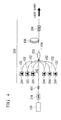
- FIG. 4 is a view illustrating a structure of the fiber laser according to a first embodiment of the present invention.
- the fiber laser of the embodiment is the same as the fiber laser shown in FIG. 3 , and is an MOPA type fiber laser which is configured to connect an MO 100 with a PA 200.
- a fiber ring laser 310 shown in FIG. 2 can be used, for example.
- the output side of the MO 100 is connected to the PA 200 via an interstage isolator 316 and a reflection device 401 which is provided at the rear stage of the interstage isolator 316.
- the laser light output from the MO 100 is amplified by the PA 200 via the interstage isolator 316 and the reflection device 401, and is output.
- the PA 200 is composed of a plurality of pump light sources 201, a photocoupler 203, a rare earth-doped double-clad fiber 105, and an isolator 206.
- the pump light source 201, the photocoupler 203, the rare earth-doped double-clad fiber 105, and the isolator 206 may be the same as those used in the fiber laser 100.
- the photocoupler 203 the photocoupler which is disclosed in Patent Document 2 is employed.
- the photocoupler 203 includes a plurality of pumping ports 102 each composed of a multi-mode optical fiber, and a signal port 202 composed of a single mode fiber, and further includes an emission port 104 which is formed by integrally fusing and extending the ports described above.
- the laser light emitted from the MO 100 is coupled to the signal port 202, and is coupled to the core of the rare earth-doped double-clad fiber 105 via the photocoupler 203.
- the pump light source 201 is connected to the pumping port 102.
- the pump light is coupled to a first clad of the rare earth-doped double-clad fiber 105 via the photocoupler 203.
- the pump light coupled to the first clad of the rare earth-doped double-clad fiber 105 is absorbed into rare earth ions which are doped in the core, and then the population inversion is formed and the stimulated emission is generated. Therefore, the laser light propagating in the core is amplified and output via the isolator 206.
- the reflected light acts as a source for the generation of oscillation, the pulses with significantly high peak power are emitted from the rare earth-doped double-clad fiber 105 to the photocoupler 203. These pulses reach the pump light source 201 or the MO 100, so that there may be risk of damage thereto.
- the fiber laser according to the embodiment is provided with the reflection device 401 between the MO 100 and the PA 200.
- the reflection device 401 is manufactured to reflect only a part of the fluorescence wavelengths of the rare earth-doped double-clad fiber 105.
- the population inversion factor (the time until oscillation starts) in which oscillation occurs is changed by the reflectance of the reflection device. As the reflectance is higher, oscillation occurs at a lower population inversion factor (oscillation occurs early). When oscillation is made to occur early, the peak power of the pulse generated by oscillation can be suppressed so as to be lower. In addition, when the reflectance at the emission side as viewed from the output port of the PA 200 is smaller than that of the reflection device 401, most power of pulses generated by the oscillation are emitted from the PA 200 to the emission side, and only a little power of pulses are emitted to the MO 100. Therefore, there is no damage on the pump light source or the MO 100.
- the reflection device 401 it is preferably that a dielectric multilayer film mirror or a fiber bragg grating (hereinafter, referred to as FBG) is used.
- the reflectance of the reflection device 401 is preferably greater than the reflectance at the emission side as viewed from the output port of the rare earth-doped double-clad fiber 105 of the PA 200, and more particularly, equal to or greater than 0.001%.
- the fiber laser according to the embodiment is provided with the reflection device 401 with a small reflectance.
- the peak power of the pulse which is emitted toward the MO 100 or the pump light source 201 by self-oscillation or reflection, can be suppressed so as to be lower by two places or more.
- the reflection device 401 with a wavelength different from the oscillation wavelength, it is possible to remove loss in signal light and efficiency degradation.
- the peak power of the pulse emitted toward the MO 100 or the pump light source 201 can be decreased, there is no damage on the pump light source 201 or the MO 100, and fiber laser with high reliability can be provided.
- the fiber laser can be manufactured at a low cost since there is no self-oscillation even though there is no PA isolator 206 which has a very high price.
- FIG. 8 is a view illustrating a structure of the fiber laser according to a second embodiment of the present invention.
- the fiber laser of this embodiment is composed of the same components as those of the fiber laser according to the first embodiment shown in FIG. 4 , and the same constitute components are designated by like reference numerals.
- the fiber laser according to this embodiment is provided with the reflection device 401, which is provided between the MO 100 and the PA 200 in the first embodiment, between the photocoupler 203 in the PA 200 and the rare earth-doped double-clad fiber 105 (that is, at the output port of the photocoupler 203).
- the peak power of the pulse which is emitted toward the MO 100 or the pump light source 201 by self-oscillation or reflection, can be suppressed so as to be lower. There is no damage on the pump light source 201 or the MO 100. A fiber laser with high reliability can be provided. Therefore, the same effect as those of the first embodiment can be obtained. Hereinafter, the effect of the present invention will be proved using embodiments.
- the known MOPA type fiber laser shown in FIG. 3 (hereinafter, referred to as a comparative example) and the fiber laser shown in FIG. 4 as the embodiment of the present invention were produced by way of experimentation.
- a fiber ring laser with an oscillation wavelength of 1064 nm is used as the MO 100.
- the rare earth-doped double-clad fiber 105 an Yb-doped double-clad fiber is used, of which the diameter of the core is 20 ⁇ m, the diameter of a first clad is 400 ⁇ m, and the absorption of the core is 1200 dB/m @976 nm.
- the photocoupler 203 a coupler which has an emission port of which the diameter of the core is 20 ⁇ m, and the diameter of the clad is 390 ⁇ m is used, in order to reduce the connection loss of the pump light between the photocoupler 203 and the rare earth-doped double-clad fiber 105.
- Pumping ports are connected to the pump light source.
- the incident port is composed of six pumping ports 102 each composed of a multi-mode fiber, of which a diameter of the core is 105 ⁇ m and NA is 0.15, and one signal port 202 composed of a single mode fiber of which a diameter of the core is 6 ⁇ m and NA is 0.14.
- the pump light source 201 six semiconductor lasers are used, and each of which has an oscillation wavelength of 915 nm and a maximum output of 5W
- FBG is provided as the reflection device 401 (the fiber laser is not provided in the comparative example).
- the reflection wavelength of the FBG may be any wavelength as long as it is in the fluorescence wavelength of the rare earth-doped double-clad fiber 105.
- the wavelength with a high gain is preferable because oscillation occurs early when the wavelength has a gain which is as high as possible.
- a filter composed of a dielectric multilayer can also be employed as there is concern that the device may be burnt out at high output, the FBG is preferable.
- the reflection wavelength is selected to be 1040 nm.
- the wavelength is set to the same wavelength as the oscillation wavelength of the MO 100, laser light emitted from the MO 100 and coupled to the PA 200 is reflected. Therefore, when the reflectance of the FBG is high, the MO 100 may be damaged. In this case, it is preferable that countermeasures are used so that the isolation of the interstage isolator 316 increases.
- FIGS. 5 and 6 respectively show the output wavelength spectrum during self-oscillation at the output port of the PA of the fiber laser of the comparative example and the fiber laser of the embodiment. At this time, the reflectance of the FBG is 0.1%.
- the fiber laser of the comparative example oscillates at random in the wavelength band with a relatively high gain of about from 1030 nm to 1075 nm.
- FIG. 5 shows that the fiber laser of the comparative example oscillates at random in the wavelength band with a relatively high gain of about from 1030 nm to 1075 nm.
- the oscillation wavelength is limited to the vicinity of 1040 nm by the insertion of the FBG.
- the wavelength band in which self-oscillation occurs when the FBG is inserted is determined by the reflection wavelength band of the FBG. Therefore, it is also possible to further limit the oscillation wavelength by using the FBG with a narrowband.
- the wavelength spectrum of light emitted from the PA 200 to the MO 100 is observed at the connection portion between the FBG and the isolator, which is shown in FIG. 7 .
- the pulse component (1040 nm) from self-oscillation has the same intensity as that of an amplified spontaneous emission (ASE) light with a different wavelength. That is, by providing the FBG, it represents that most power of pulses generated by self-oscillation are emitted toward the output port of the rare earth-doped double-clad fiber 105.
- the peak power of the pulse during self-oscillation is 9 W at the output port of the laser, 5 W at the output port of the interstage isolator, and 1 W at the pumping port.
- the peak value of the pulse during self-oscillation is 17 W at the output port of the laser, 0.02 W at the output port of the interstage isolator, and 0.007 W at the pumping port.
- the peak value of the pulse emitted from the PA 200 to the MO 100 can be taken down about two places or more.
- the reflectance of the FBG in the embodiment is 0.1%, but when the reflectance increases, the peak power of the pulse emitted from the PA 200 to the MO 100 can be further decreased.
- a metal plate is provided at a position to which the laser is emitted from the PA 200.
- the peak power at the output port of the interstage isolator is 6 W.
- the peak power at the output port of the interstage isolator is 0.3 W. Therefore, even when the reflected light is coupled again, the peak power of pulse emitted from the PA to the MO is weak.
- the reflectance of the reflected light to be coupled again to the output port is changed according to the actual use condition, but it may be sufficient that the reflectance of the FBG becomes large.
- the reflectance at the emission side does not become equal to or less than the reflectance of the PA isolator.
- the reflectance of the isolator subjected to a low reflection treatment is 0.001%. Therefore, it is preferable that the reflectance of the FBG be equal to or greater than 0.001 %.
- the reflectance of the grating be in a range of about from 0.001% to 10%.
- the gain of the reflection wavelength of the rare earth-doped double-clad fiber of the FBG is preferably equal to or more than the gain of the oscillation wavelength of the MO. This is because oscillation easily occurs in accordance with the amplitude of the gain.
- the oscillation wavelength of the MO is different from the reflection wavelength of the FBG, but if the two wavelengths are the same, the same effect can be obtained. In this case, since there is loss in the laser light from the MO 100, it is preferable that the wavelengths be different from each other.
- the reflectance is extremely high, the reflected laser light is coupled again to the MO 100, so that the components in the MO 100 may be damaged.
- the reflectance is appropriately selected so as not to cause such a result, and preferably, the reflectance is 10% or less.
- FIG. 8 is shows a second embodiment of the present invention. Specifically, the structure thereof is the same as that of the first embodiment described above, but is different from that shown in FIG. 4 in that the reflection device 401 is connected to the emission port 104 of the photocoupler 203, and the rare earth-doped double-clad fiber 105 is connected to the rear stage thereof. That is, the position of the reflection device 401 is different from that of the first embodiment.
- the reflection device 401 is provided at the incident terminal of the photocoupler. Therefore, since the photocoupler is included in a resonator during self-oscillation, an oscillation light emitted from the rare earth-doped double-clad fiber 105 reaches the pump light source via the photocoupler 203. Therefore, a pulse with a relatively high peak power can be coupled to the pump light source 201.
- the reflection device 401 is disposed on the position shown in FIG. 8 , and because of this, the power of the pulse coupled to the pump light source 201 can be further reduced. Under the same pumping condition as the first embodiment, the fiber laser is driven, so that the peak power of the pulse coupled to the pump light source 201 is 0.2 mW. As a result, compared with the first embodiment, the peak power can be taken down about one place.
- the fiber laser is provided with the reflection device with a small reflectance.
- the peak power of the pulse which is emitted toward the MO or the pump light source by self-oscillation or reflection, can be suppressed so as to be taken it down about two places.
- the reflection device with a wavelength different from the oscillation wavelength, it is possible to remove efficiency degradation without causing loss in signal light.
- the peak power of the pulse emitted toward the MO or the pump light source can be reduced, there is no damage on the pump light source or the MO, and a laser with high reliability can be provided. That is, it is possible to improve the reliability of the fiber laser.
- the fiber laser can be manufactured at a low cost since self-oscillation can be eliminated without a PA isolator which is a very expensive element.
Landscapes
- Physics & Mathematics (AREA)
- Electromagnetism (AREA)
- Engineering & Computer Science (AREA)
- Plasma & Fusion (AREA)
- Optics & Photonics (AREA)
- Lasers (AREA)
Applications Claiming Priority (2)
| Application Number | Priority Date | Filing Date | Title |
|---|---|---|---|
| JP2007132755 | 2007-05-18 | ||
| PCT/JP2008/058842 WO2008143084A1 (ja) | 2007-05-18 | 2008-05-14 | ファイバレーザ |
Publications (3)
| Publication Number | Publication Date |
|---|---|
| EP2154759A1 true EP2154759A1 (de) | 2010-02-17 |
| EP2154759A8 EP2154759A8 (de) | 2010-10-06 |
| EP2154759A4 EP2154759A4 (de) | 2011-02-09 |
Family
ID=40031793
Family Applications (1)
| Application Number | Title | Priority Date | Filing Date |
|---|---|---|---|
| EP08752713A Withdrawn EP2154759A4 (de) | 2007-05-18 | 2008-05-14 | Faserlaser |
Country Status (5)
| Country | Link |
|---|---|
| US (1) | US8279899B2 (de) |
| EP (1) | EP2154759A4 (de) |
| JP (1) | JP5185929B2 (de) |
| CN (1) | CN101682163B (de) |
| WO (1) | WO2008143084A1 (de) |
Cited By (1)
| Publication number | Priority date | Publication date | Assignee | Title |
|---|---|---|---|---|
| CN103944056A (zh) * | 2014-04-02 | 2014-07-23 | 中国电子科技集团公司第二十六研究所 | 一种mopa结构的声光调q脉冲光纤激光器 |
Families Citing this family (45)
| Publication number | Priority date | Publication date | Assignee | Title |
|---|---|---|---|---|
| JP5578935B2 (ja) * | 2010-05-20 | 2014-08-27 | 株式会社アマダミヤチ | ファイバレーザ加工装置 |
| US8650914B2 (en) | 2010-09-23 | 2014-02-18 | Johns Manville | Methods and apparatus for recycling glass products using submerged combustion |
| US8997525B2 (en) | 2010-06-17 | 2015-04-07 | Johns Manville | Systems and methods for making foamed glass using submerged combustion |
| US8991215B2 (en) | 2010-06-17 | 2015-03-31 | Johns Manville | Methods and systems for controlling bubble size and bubble decay rate in foamed glass produced by a submerged combustion melter |
| US9032760B2 (en) | 2012-07-03 | 2015-05-19 | Johns Manville | Process of using a submerged combustion melter to produce hollow glass fiber or solid glass fiber having entrained bubbles, and burners and systems to make such fibers |
| US8707740B2 (en) | 2011-10-07 | 2014-04-29 | Johns Manville | Submerged combustion glass manufacturing systems and methods |
| US8973405B2 (en) | 2010-06-17 | 2015-03-10 | Johns Manville | Apparatus, systems and methods for reducing foaming downstream of a submerged combustion melter producing molten glass |
| US9096452B2 (en) | 2010-06-17 | 2015-08-04 | Johns Manville | Methods and systems for destabilizing foam in equipment downstream of a submerged combustion melter |
| US9021838B2 (en) | 2010-06-17 | 2015-05-05 | Johns Manville | Systems and methods for glass manufacturing |
| US8875544B2 (en) | 2011-10-07 | 2014-11-04 | Johns Manville | Burner apparatus, submerged combustion melters including the burner, and methods of use |
| US9776903B2 (en) | 2010-06-17 | 2017-10-03 | Johns Manville | Apparatus, systems and methods for processing molten glass |
| US10322960B2 (en) | 2010-06-17 | 2019-06-18 | Johns Manville | Controlling foam in apparatus downstream of a melter by adjustment of alkali oxide content in the melter |
| US8769992B2 (en) | 2010-06-17 | 2014-07-08 | Johns Manville | Panel-cooled submerged combustion melter geometry and methods of making molten glass |
| US8707739B2 (en) | 2012-06-11 | 2014-04-29 | Johns Manville | Apparatus, systems and methods for conditioning molten glass |
| RU2591586C2 (ru) * | 2011-08-18 | 2016-07-20 | Ай-Пи-Джи Фоутоникс Корпорейшн | ВЫСОКОМОЩНЫЙ ВОЛОКОННЫЙ ИСТОЧНИК НАКАЧКИ С ВЫСОКОЯРКИМ МАЛОШУМЯЩИМ ВЫХОДНЫМ ИЗЛУЧЕНИЕМ В ДИАПАЗОНЕ ДЛИН ВОЛН 974-1030 нм |
| JP2013055283A (ja) | 2011-09-06 | 2013-03-21 | Fujikura Ltd | 高パワーパルス光発生装置 |
| US9533905B2 (en) | 2012-10-03 | 2017-01-03 | Johns Manville | Submerged combustion melters having an extended treatment zone and methods of producing molten glass |
| WO2014055199A1 (en) | 2012-10-03 | 2014-04-10 | Johns Manville | Methods and systems for destabilizing foam in equipment downstream of a submerged combustion melter |
| US9227865B2 (en) | 2012-11-29 | 2016-01-05 | Johns Manville | Methods and systems for making well-fined glass using submerged combustion |
| US10138151B2 (en) | 2013-05-22 | 2018-11-27 | Johns Manville | Submerged combustion burners and melters, and methods of use |
| US10131563B2 (en) | 2013-05-22 | 2018-11-20 | Johns Manville | Submerged combustion burners |
| WO2014189501A1 (en) | 2013-05-22 | 2014-11-27 | Johns Manville | Submerged combustion burners, melters, and methods of use |
| WO2014189499A1 (en) | 2013-05-22 | 2014-11-27 | Johns Manville | Submerged combustion burners and melters, and methods of use |
| PL2999923T3 (pl) | 2013-05-22 | 2019-02-28 | Johns Manville | Piec do topienia ze spalaniem pod powierzchnią cieczy z udoskonalonym palnikiem oraz odpowiadający sposób |
| EP3003997B1 (de) | 2013-05-30 | 2021-04-28 | Johns Manville | Brenner für unterwasserverbrennung mit mischverbesserungsmittel für glasschmelzer, und verwendung |
| SI3003996T1 (sl) | 2013-05-30 | 2020-11-30 | Johns Manville | Sistemi potopnega zgorevanja za taljenje stekla in postopki uporabe |
| US10858278B2 (en) | 2013-07-18 | 2020-12-08 | Johns Manville | Combustion burner |
| US9768581B2 (en) * | 2015-01-21 | 2017-09-19 | Ofs Fitel, Llc | Pump and signal combiner for high numerical aperture use |
| US9751792B2 (en) | 2015-08-12 | 2017-09-05 | Johns Manville | Post-manufacturing processes for submerged combustion burner |
| US10041666B2 (en) | 2015-08-27 | 2018-08-07 | Johns Manville | Burner panels including dry-tip burners, submerged combustion melters, and methods |
| US10670261B2 (en) | 2015-08-27 | 2020-06-02 | Johns Manville | Burner panels, submerged combustion melters, and methods |
| US9815726B2 (en) | 2015-09-03 | 2017-11-14 | Johns Manville | Apparatus, systems, and methods for pre-heating feedstock to a melter using melter exhaust |
| WO2017044799A1 (en) * | 2015-09-10 | 2017-03-16 | Massachusetts Institute Of Technology | Systems, apparatus, and methods for laser amplification in fiber amplifiers |
| US9982884B2 (en) | 2015-09-15 | 2018-05-29 | Johns Manville | Methods of melting feedstock using a submerged combustion melter |
| US10837705B2 (en) | 2015-09-16 | 2020-11-17 | Johns Manville | Change-out system for submerged combustion melting burner |
| US10081563B2 (en) | 2015-09-23 | 2018-09-25 | Johns Manville | Systems and methods for mechanically binding loose scrap |
| US10144666B2 (en) | 2015-10-20 | 2018-12-04 | Johns Manville | Processing organics and inorganics in a submerged combustion melter |
| CN105978445B (zh) * | 2016-06-20 | 2017-12-15 | 江苏中天科技股份有限公司 | 一种基于多结聚光光伏电池的光纤供能系统及其供能方法 |
| US10246362B2 (en) | 2016-06-22 | 2019-04-02 | Johns Manville | Effective discharge of exhaust from submerged combustion melters and methods |
| US10337732B2 (en) | 2016-08-25 | 2019-07-02 | Johns Manville | Consumable tip burners, submerged combustion melters including same, and methods |
| US10301208B2 (en) | 2016-08-25 | 2019-05-28 | Johns Manville | Continuous flow submerged combustion melter cooling wall panels, submerged combustion melters, and methods of using same |
| US10196294B2 (en) | 2016-09-07 | 2019-02-05 | Johns Manville | Submerged combustion melters, wall structures or panels of same, and methods of using same |
| US10233105B2 (en) | 2016-10-14 | 2019-03-19 | Johns Manville | Submerged combustion melters and methods of feeding particulate material into such melters |
| CN110556693A (zh) * | 2019-09-20 | 2019-12-10 | 广东国志激光技术有限公司 | 光纤激光器 |
| CN117353141B (zh) * | 2023-11-02 | 2024-04-16 | 上海频准激光科技有限公司 | 抑制放大边缘波长时的自激振荡的光纤放大器和放大方法 |
Family Cites Families (18)
| Publication number | Priority date | Publication date | Assignee | Title |
|---|---|---|---|---|
| JP2653936B2 (ja) | 1991-05-17 | 1997-09-17 | 沖電気工業株式会社 | 光増幅器 |
| JP2977053B2 (ja) | 1991-07-12 | 1999-11-10 | 安藤電気株式会社 | 高出力光パルス発生器 |
| JPH05136498A (ja) | 1991-07-22 | 1993-06-01 | Oki Electric Ind Co Ltd | 光増幅器 |
| US5659644A (en) | 1996-06-07 | 1997-08-19 | Lucent Technologies Inc. | Fiber light source with multimode fiber coupler |
| US5864644A (en) | 1997-07-21 | 1999-01-26 | Lucent Technologies Inc. | Tapered fiber bundles for coupling light into and out of cladding-pumped fiber devices |
| KR100360983B1 (ko) * | 1999-10-06 | 2002-11-18 | 주식회사 머큐리 | 장파장대역용 광섬유증폭기 |
| WO2001063818A1 (en) * | 2000-02-23 | 2001-08-30 | Tedram, Optical Networks, Inc. | Distributed amplification edfl multiple wavelength laser source |
| US7190705B2 (en) * | 2000-05-23 | 2007-03-13 | Imra America. Inc. | Pulsed laser sources |
| CA2343091C (en) * | 2000-05-25 | 2009-09-08 | Kyocera Corporation | Broadband amplified spontaneous emission light source |
| JP2002252399A (ja) * | 2001-02-23 | 2002-09-06 | Tomomi Sudo | 光増幅器 |
| US20050024716A1 (en) * | 2003-07-15 | 2005-02-03 | Johan Nilsson | Optical device with immediate gain for brightness enhancement of optical pulses |
| US20050207455A1 (en) * | 2003-12-15 | 2005-09-22 | Maccormack Stuart | Method and apparatus for efficient coupling of pump light into fiber amplifiers |
| EP1733460A4 (de) * | 2004-01-30 | 2009-04-15 | Nufern | Verfahren und vorrichtung zur bereitstellung von licht mit selektiver polarisation mit einer optischen faser |
| JP2005251999A (ja) * | 2004-03-04 | 2005-09-15 | Toyota Gakuen | 光機能導波路材料および光増幅媒体、光増幅器、レーザ装置、光源 |
| JP2006319219A (ja) * | 2005-05-13 | 2006-11-24 | Fujikura Ltd | 多モード光ファイバ及びその利用 |
| US7539231B1 (en) * | 2005-07-15 | 2009-05-26 | Lockheed Martin Corporation | Apparatus and method for generating controlled-linewidth laser-seed-signals for high-powered fiber-laser amplifier systems |
| JP4699131B2 (ja) | 2005-08-05 | 2011-06-08 | 株式会社フジクラ | 光ファイバレーザ、光ファイバ増幅器、mopa方式光ファイバレーザ |
| JP4732120B2 (ja) * | 2005-10-19 | 2011-07-27 | 株式会社フジクラ | 光増幅用光ファイバの製造方法 |
-
2008
- 2008-05-14 JP JP2009515169A patent/JP5185929B2/ja active Active
- 2008-05-14 EP EP08752713A patent/EP2154759A4/de not_active Withdrawn
- 2008-05-14 WO PCT/JP2008/058842 patent/WO2008143084A1/ja not_active Ceased
- 2008-05-14 CN CN2008800165007A patent/CN101682163B/zh not_active Expired - Fee Related
-
2009
- 2009-11-18 US US12/621,318 patent/US8279899B2/en not_active Expired - Fee Related
Cited By (1)
| Publication number | Priority date | Publication date | Assignee | Title |
|---|---|---|---|---|
| CN103944056A (zh) * | 2014-04-02 | 2014-07-23 | 中国电子科技集团公司第二十六研究所 | 一种mopa结构的声光调q脉冲光纤激光器 |
Also Published As
| Publication number | Publication date |
|---|---|
| US8279899B2 (en) | 2012-10-02 |
| US20100061409A1 (en) | 2010-03-11 |
| JPWO2008143084A1 (ja) | 2010-08-05 |
| EP2154759A4 (de) | 2011-02-09 |
| EP2154759A8 (de) | 2010-10-06 |
| CN101682163A (zh) | 2010-03-24 |
| WO2008143084A1 (ja) | 2008-11-27 |
| CN101682163B (zh) | 2011-10-05 |
| JP5185929B2 (ja) | 2013-04-17 |
Similar Documents
| Publication | Publication Date | Title |
|---|---|---|
| US8279899B2 (en) | Fiber laser | |
| US8270442B2 (en) | Optical fiber laser | |
| CN102449864B (zh) | 用于高功率水平的级联拉曼激光发射的系统和方法 | |
| US7738166B2 (en) | Fiber amplifier with integrated fiber laser pump | |
| JP5260146B2 (ja) | 光源装置 | |
| JP5198292B2 (ja) | 反射光耐性の優れたファイバレーザ | |
| EP2916400B1 (de) | Hybridisolator und modenvergrösserer für faserlaserverstärker | |
| EP1147579A1 (de) | Pumpvorrichtung mit optischem wellenleiter, einem halbleiter- und einem festkörperlaser sowie zugehöriges pumpverfahren | |
| EP3005496B1 (de) | Multimodaler fabry-perot-faserlaser | |
| JP5623706B2 (ja) | レーザ光源 | |
| WO2009082733A1 (en) | High power pulsed fiber laser | |
| JP3344475B2 (ja) | レーザ発振器及びレーザ増幅器 | |
| US20060262388A1 (en) | Fiber amplifier with suppression of amplified spontaneous emission | |
| US20060187973A1 (en) | Eye safe high power fibre laser | |
| JP4708109B2 (ja) | ファイバレーザ装置 | |
| CA2978728C (en) | Method and apparatus for providing amplified radiation | |
| JP5151018B2 (ja) | 光源装置 | |
| JP4848836B2 (ja) | 光活性デバイス | |
| JP4910328B2 (ja) | 光増幅装置およびレーザ光源装置 | |
| Codemard et al. | High-brightness, pulsed, cladding-pumped Raman fiber source at 1660 nm | |
| JP2006222352A (ja) | 光ファイバレーザ及び光ファイバ増幅器 | |
| JP2012044224A (ja) | 光増幅装置およびレーザ光源装置 | |
| Boullet et al. | Yb-doped fiber laser system generating 12-ns 0.7-mJ pulses at 82 kHz at 977 nm | |
| JP2002246673A (ja) | 光増幅器 |
Legal Events
| Date | Code | Title | Description |
|---|---|---|---|
| PUAI | Public reference made under article 153(3) epc to a published international application that has entered the european phase |
Free format text: ORIGINAL CODE: 0009012 |
|
| 17P | Request for examination filed |
Effective date: 20091125 |
|
| AK | Designated contracting states |
Kind code of ref document: A1 Designated state(s): AT BE BG CH CY CZ DE DK EE ES FI FR GB GR HR HU IE IS IT LI LT LU LV MC MT NL NO PL PT RO SE SI SK TR |
|
| AX | Request for extension of the european patent |
Extension state: AL BA MK RS |
|
| DAX | Request for extension of the european patent (deleted) | ||
| RAP1 | Party data changed (applicant data changed or rights of an application transferred) |
Owner name: FUJIKURA LTD. |
|
| A4 | Supplementary search report drawn up and despatched |
Effective date: 20110112 |
|
| STAA | Information on the status of an ep patent application or granted ep patent |
Free format text: STATUS: THE APPLICATION HAS BEEN WITHDRAWN |
|
| 18W | Application withdrawn |
Effective date: 20141021 |