EP2154765A1 - Alimentation electrique pour fournir de l'energie stockee dans une partie de stockage et systeme d'alimentation electrique ayant son alimentation electrique - Google Patents
Alimentation electrique pour fournir de l'energie stockee dans une partie de stockage et systeme d'alimentation electrique ayant son alimentation electrique Download PDFInfo
- Publication number
- EP2154765A1 EP2154765A1 EP08739400A EP08739400A EP2154765A1 EP 2154765 A1 EP2154765 A1 EP 2154765A1 EP 08739400 A EP08739400 A EP 08739400A EP 08739400 A EP08739400 A EP 08739400A EP 2154765 A1 EP2154765 A1 EP 2154765A1
- Authority
- EP
- European Patent Office
- Prior art keywords
- storage unit
- power storage
- load
- power
- voltage
- Prior art date
- Legal status (The legal status is an assumption and is not a legal conclusion. Google has not performed a legal analysis and makes no representation as to the accuracy of the status listed.)
- Withdrawn
Links
Images
Classifications
-
- H—ELECTRICITY
- H02—GENERATION; CONVERSION OR DISTRIBUTION OF ELECTRIC POWER
- H02M—APPARATUS FOR CONVERSION BETWEEN AC AND AC, BETWEEN AC AND DC, OR BETWEEN DC AND DC, AND FOR USE WITH MAINS OR SIMILAR POWER SUPPLY SYSTEMS; CONVERSION OF DC OR AC INPUT POWER INTO SURGE OUTPUT POWER; CONTROL OR REGULATION THEREOF
- H02M3/00—Conversion of DC power input into DC power output
- H02M3/02—Conversion of DC power input into DC power output without intermediate conversion into AC
- H02M3/04—Conversion of DC power input into DC power output without intermediate conversion into AC by static converters
- H02M3/10—Conversion of DC power input into DC power output without intermediate conversion into AC by static converters using discharge tubes with control electrode or semiconductor devices with control electrode
- H02M3/145—Conversion of DC power input into DC power output without intermediate conversion into AC by static converters using discharge tubes with control electrode or semiconductor devices with control electrode using devices of a triode or transistor type requiring continuous application of a control signal
- H02M3/155—Conversion of DC power input into DC power output without intermediate conversion into AC by static converters using discharge tubes with control electrode or semiconductor devices with control electrode using devices of a triode or transistor type requiring continuous application of a control signal using semiconductor devices only
- H02M3/156—Conversion of DC power input into DC power output without intermediate conversion into AC by static converters using discharge tubes with control electrode or semiconductor devices with control electrode using devices of a triode or transistor type requiring continuous application of a control signal using semiconductor devices only with automatic control of output voltage or current, e.g. switching regulators
- H02M3/158—Conversion of DC power input into DC power output without intermediate conversion into AC by static converters using discharge tubes with control electrode or semiconductor devices with control electrode using devices of a triode or transistor type requiring continuous application of a control signal using semiconductor devices only with automatic control of output voltage or current, e.g. switching regulators including plural semiconductor devices as final control devices for a single load
-
- H—ELECTRICITY
- H01—ELECTRIC ELEMENTS
- H01M—PROCESSES OR MEANS, e.g. BATTERIES, FOR THE DIRECT CONVERSION OF CHEMICAL ENERGY INTO ELECTRICAL ENERGY
- H01M10/00—Secondary cells; Manufacture thereof
- H01M10/42—Methods or arrangements for servicing or maintenance of secondary cells or secondary half-cells
- H01M10/44—Methods for charging or discharging
- H01M10/441—Methods for charging or discharging for several batteries or cells simultaneously or sequentially
-
- H—ELECTRICITY
- H02—GENERATION; CONVERSION OR DISTRIBUTION OF ELECTRIC POWER
- H02J—ELECTRIC POWER NETWORKS; CIRCUIT ARRANGEMENTS OR SYSTEMS FOR SUPPLYING OR DISTRIBUTING ELECTRIC POWER; SYSTEMS FOR STORING ELECTRIC ENERGY
- H02J1/00—Circuit arrangements for DC mains or DC distribution networks
- H02J1/10—Parallel operation of DC sources
- H02J1/108—Parallel operation of DC sources having arrangements for blocking reverse current flow, e.g. using diodes
-
- H—ELECTRICITY
- H02—GENERATION; CONVERSION OR DISTRIBUTION OF ELECTRIC POWER
- H02J—ELECTRIC POWER NETWORKS; CIRCUIT ARRANGEMENTS OR SYSTEMS FOR SUPPLYING OR DISTRIBUTING ELECTRIC POWER; SYSTEMS FOR STORING ELECTRIC ENERGY
- H02J7/00—Circuit arrangements for charging or discharging batteries or for supplying loads from batteries
- H02J7/34—Parallel operation in networks using both storage and other DC sources, e.g. providing buffering
- H02J7/345—Parallel operation in networks using both storage and other DC sources, e.g. providing buffering using capacitors as storage or buffering devices
-
- H—ELECTRICITY
- H02—GENERATION; CONVERSION OR DISTRIBUTION OF ELECTRIC POWER
- H02M—APPARATUS FOR CONVERSION BETWEEN AC AND AC, BETWEEN AC AND DC, OR BETWEEN DC AND DC, AND FOR USE WITH MAINS OR SIMILAR POWER SUPPLY SYSTEMS; CONVERSION OF DC OR AC INPUT POWER INTO SURGE OUTPUT POWER; CONTROL OR REGULATION THEREOF
- H02M3/00—Conversion of DC power input into DC power output
- H02M3/02—Conversion of DC power input into DC power output without intermediate conversion into AC
- H02M3/04—Conversion of DC power input into DC power output without intermediate conversion into AC by static converters
- H02M3/10—Conversion of DC power input into DC power output without intermediate conversion into AC by static converters using discharge tubes with control electrode or semiconductor devices with control electrode
- H02M3/145—Conversion of DC power input into DC power output without intermediate conversion into AC by static converters using discharge tubes with control electrode or semiconductor devices with control electrode using devices of a triode or transistor type requiring continuous application of a control signal
- H02M3/155—Conversion of DC power input into DC power output without intermediate conversion into AC by static converters using discharge tubes with control electrode or semiconductor devices with control electrode using devices of a triode or transistor type requiring continuous application of a control signal using semiconductor devices only
- H02M3/156—Conversion of DC power input into DC power output without intermediate conversion into AC by static converters using discharge tubes with control electrode or semiconductor devices with control electrode using devices of a triode or transistor type requiring continuous application of a control signal using semiconductor devices only with automatic control of output voltage or current, e.g. switching regulators
- H02M3/158—Conversion of DC power input into DC power output without intermediate conversion into AC by static converters using discharge tubes with control electrode or semiconductor devices with control electrode using devices of a triode or transistor type requiring continuous application of a control signal using semiconductor devices only with automatic control of output voltage or current, e.g. switching regulators including plural semiconductor devices as final control devices for a single load
- H02M3/1584—Conversion of DC power input into DC power output without intermediate conversion into AC by static converters using discharge tubes with control electrode or semiconductor devices with control electrode using devices of a triode or transistor type requiring continuous application of a control signal using semiconductor devices only with automatic control of output voltage or current, e.g. switching regulators including plural semiconductor devices as final control devices for a single load with a plurality of power processing stages connected in parallel
-
- Y—GENERAL TAGGING OF NEW TECHNOLOGICAL DEVELOPMENTS; GENERAL TAGGING OF CROSS-SECTIONAL TECHNOLOGIES SPANNING OVER SEVERAL SECTIONS OF THE IPC; TECHNICAL SUBJECTS COVERED BY FORMER USPC CROSS-REFERENCE ART COLLECTIONS [XRACs] AND DIGESTS
- Y02—TECHNOLOGIES OR APPLICATIONS FOR MITIGATION OR ADAPTATION AGAINST CLIMATE CHANGE
- Y02E—REDUCTION OF GREENHOUSE GAS [GHG] EMISSIONS, RELATED TO ENERGY GENERATION, TRANSMISSION OR DISTRIBUTION
- Y02E60/00—Enabling technologies; Technologies with a potential or indirect contribution to GHG emissions mitigation
- Y02E60/10—Energy storage using batteries
Definitions
- the present invention relates to a power supply apparatus, and more particularly to a power supply apparatus converting electric power stored in a power storage unit into a prescribed voltage for supply to a load and a power supply system including the power supply apparatus.
- Photovoltaic power generators having a power storage function are useful as an apparatus for bringing electric equipment into operation at places where commercial electric power is not distributed.
- An example of compact photovoltaic power generators having a power storage function is an apparatus supplying electric power to garden lights used in residential gardens where electrical wiring is not installed, that is, an apparatus storing electric power of solar cells during the daytime and discharging and supplying electric power to the lights during the night.
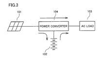
- Fig. 3 is a diagram showing a configuration of a conventional interconnection system for a photovoltaic power generation system having a power storage function.
- this interconnection system includes a solar battery 101, a storage battery 102, an alternating current (AC) load 103, and a power converter 104.
- power converter 104 outputs current to a commercial power system of AC (Alternating Current) 200V in place of AC load 103.
- AC Alternating Current
- Patent Document 1 discloses a vehicle engine start control apparatus as follows. Specifically, an engine start control apparatus for a vehicle installed with an engine generating driving force of the vehicle and an engine starting apparatus receiving power supply to start the engine includes first and second power storage apparatuses capable of supplying the stored power to the engine starting apparatus and a starting current control unit provided between the first and second power storage apparatuses and the engine starting apparatus to supply operating current for the engine starting apparatus by means of at least one of the first and second starting current from the first and second power storage apparatuses, respectively.
- the starting current control unit controls the proportion of the first and second starting current of the operating current, depending on a state of the vehicle at a time of engine start. Because of such a configuration, in a vehicle in which operating current can be supplied to the engine starting apparatus by both the first power storage apparatus (secondary battery) and the second power storage apparatus (capacitor), a proper balance of current supply from them can be attained depending on a vehicle state. Therefore, at a time of supplying operating current to the engine starting apparatus that consumes much power, an output voltage drop caused by excessive output current can be prevented in either power storage apparatus, thereby achieving smooth and stable vehicle operations.
- Patent Document 2 discloses voltage-dependent vehicle-mounted equipment as follows. Specifically, the voltage-dependent vehicle-mounted equipment is connected to an ACC (accessory) power supply of a vehicle and/or a battery, and a capacitor bank is connected to and charged by the ACC power supply and/or the battery to supply electric power to the voltage-dependent vehicle-mounted equipment when the electric power supplied to the voltage-dependent vehicle-mounted equipment becomes a prescribed value or lower. Because of such a configuration, it becomes possible to instantaneously supply electric power from the capacitor bank to the voltage-dependent vehicle-mounted equipment in response to a momentary power drop due to restarting of the engine of an idling stop vehicle. Therefore, it is possible to provide a voltage-dependent vehicle-mounted equipment immune to a momentary power drop and an environmentally-friendly automobile of good performance.
- ACC accessory
- a capacitor bank is connected to and charged by the ACC power supply and/or the battery to supply electric power to the voltage-dependent vehicle-mounted equipment when the electric power supplied to the voltage-dependent vehicle-mounted equipment becomes
- Patent Documents 1 and 2 relate to a system supplying output voltage of a storage battery to a load as it is without voltage conversion of increasing or decreasing voltage and cannot supply power to a load operating at a voltage higher than the output voltage of the storage battery.
- the output voltage of storage battery 102 need to be once increased by power converter 104 before DC to AC conversion.
- An object of the present invention is therefore to provide a power supply apparatus capable of increasing output voltage of a power storage unit such as a storage battery for supply to a load and of stably supplying voltage to a load, and a power supply system including the power supply apparatus.
- a power supply apparatus in accordance with an aspect of the present invention converts electric power stored in a first power storage unit into a prescribed voltage for supply to a load.
- the power supply apparatus includes: a power storage unit-side terminal coupled to the first power storage unit; a second power storage unit; a load-side terminal coupled to the load; a converter unit for increasing output voltage of the first power storage unit to a first voltage and outputting the first voltage to the load-side terminal at a time of discharging of the first power storage unit; a step-up circuit for increasing output voltage of the first power storage unit and supplying the increased voltage to the second power storage unit; and a backflow prevention circuit arranged between the second power storage unit and the load-side terminal to allow current to flow from the second power storage unit to the load-side terminal and block current flowing from the load-side terminal to the second power storage unit.
- the step-up circuit increases output voltage of the first power storage unit and supplies the increased voltage to the second power storage unit such that output voltage of the second power storage unit is smaller than the first voltage.
- the backflow prevention circuit includes a diode having an anode coupled to the second power storage unit and a cathode coupled to the load-side terminal.
- the converter unit decreases voltage supplied from the load-side terminal and supplies the decreased voltage to the first power storage unit at a time of charging of the first power storage unit.
- the first power storage unit is a storage battery
- the second power storage unit is a capacitor
- a power supply system supplying electric power to a load includes: a first power storage unit; a second power storage unit; a load-side terminal coupled to the load; a converter unit for increasing output voltage of the first power storage unit to a first voltage and outputting the first voltage to the load-side terminal at a time of discharging of the first power storage unit; a step-up circuit for increasing output voltage of the first power storage unit and supplying the increased voltage to the second power storage unit; and a backflow prevention circuit arranged between the second power storage unit and the load-side terminal to allow current to flow from the second power storage unit to the load-side terminal and block current flowing from the load-side terminal to the second power storage unit.
- 1 storage battery (first power storage unit), 2 bidirectional DC-DC converter, 3 capacitor (second power storage unit), 4 step-up circuit, 5 diode (backflow prevention circuit), 6 power supply apparatus, 7 DC load, 9, 10, 12 switch element, 11, 13 reactor, 14 diode, 15 capacitor, 51 power supply system, 101 solar battery, 102 storage battery, 103 AC load, 104 power converter, T1, T2 load-side terminal, T3, T4 storage battery-side terminal.
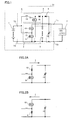
- Fig. 1 is a diagram showing a configuration of a power supply system in accordance with an embodiment of the present invention.
- a power supply system 51 includes a storage battery (first power storage unit) 1 and a power supply apparatus 6.
- Power supply apparatus 6 includes a bidirectional DC-DC converter (converter unit) 2, a capacitor (second power storage unit) 3, a step-up circuit 4, a diode (backflow prevention circuit) 5, load-side terminals T1 and T2, and storage battery-side terminals T3 and T4.
- Bidirectional DC-DC converter 2 includes switch elements 9 and 10, a rector 11, and a capacitor 15.
- Step-up circuit 4 includes a switch element 12, a rector 13, and a diode 14.
- Secondary batteries such as lead-acid batteries, nickel metal hydride batteries, and lithium ion batteries can be used as storage battery (first power storage unit) 1.
- a lithium ion battery is used and the output voltage is about 3-4V.
- Switch elements such as MOS (Metal Oxide Semiconductor) FET (Field Effect Transistor) and IGBT (Insulated Gate Bipolar Transistor) can be used as switch elements 9, 10, 12.
- MOSFET Metal Oxide Semiconductor
- the positive terminal of storage battery 1, the first end of reactor 11, and the first end of reactor 13 are connected with storage battery-side terminal T3.
- the drain of switch element 9 and the source of switch element 10 are connected with the second terminal of reactor 11.
- the positive terminal of capacitor 15, the cathode of diode 5, and load-side terminal T1 are connected with the drain of switch element 10.
- the drain of switch element 12 and the anode of diode 4 are connected with the second end of reactor 13.
- the first end of capacitor 3 and the anode of diode 5 are connected with the cathode of diode 4.
- Storage battery-side terminal T4, the source of switch element 9, and the source of switch element 12, the second terminal of capacitor 3, the negative terminal of capacitor 15, and load-side terminal T2 are connected with each other.
- the output voltage of storage battery 1 is increased by bidirectional DC-DC converter 2.
- the output side of bidirectional DC-DC converter 2 is connected to load-side terminals T1 and T2.
- Load-side terminals T1 and T2 are connected to a DC load 7.
- the output voltage of bidirectional DC-DC converter 2 is subjected to constant voltage control so as to fall within a prescribed voltage range in which DC load 7 is operable.
- the output voltage of bidirectional DC-DC converter 2 is 12V.
- bidirectional DC-DC converter 2 When a charger is connected to load-side terminals T1 and T2, bidirectional DC-DC converter 2 performs a voltage conversion operation of decreasing the voltage supplied from the charger through load-side terminals T1 and T2 to an input voltage for storage battery 1.
- Step-up circuit 4 is connected to storage battery 1 in parallel with bidirectional DC-DC converter 2.
- the output of step-up circuit 4 is connected to capacitor 3.
- Capacitor 3 which is also called, for example, an electric double layer capacitor, is an element in which voltage drop at a time of large current output is smaller than that of storage battery 1 since the capacitance is extremely large.
- a power storage element having a similar function such as an electrolytic capacitor, can be used.
- Step-up circuit 4 is subjected to constant voltage control so that it outputs a voltage slightly lower than the output voltage of bidirectional DC-DC converter 2. More specifically, step-up circuit 4 supplies voltage to capacitor 3 for charging such that the output voltage from capacitor 3 to load-side terminals T1 and T2 is lower than the output voltage of bidirectional DC-DC converter 2.
- the output voltage of capacitor 3 is 11V.
- Diode 5 is connected between capacitor 3 and load-side terminal T1, that is, between capacitor 3 and bidirectional DC-DC converter 2, wherein the direction from capacitor 3 to load-side terminal T1 is the forward direction.
- diode 5 is arranged between capacitor 3 and load-side terminal T1 to allow current to flow from capacitor 3 to load-side terminal T1 and block current flowing from load-side terminal T1 to capacitor 3.
- Fig. 2A is a diagram showing an operation in bidirectional DC-DC converter 2 at a time of discharging of storage battery 1.
- Fig. 2B is a diagram showing an operation in bidirectional DC-DC converter 2 at a time of charging of storage battery 1.
- the flow of current is represented by I.
- the operation of bidirectional DC-DC converter 2 at a time of discharging of storage battery 1 is referred to as a "forward-direction operation.”
- the operation of bidirectional DC-DC converter 2 at a time of charging of storage battery 1 is referred to as a "reverse-direction operation.”
- switch element 10 is always controlled in an off state. Therefore, only a body diode included in switch element 10 functions. Furthermore, switch element 9 is switching-controlled at a high frequency of 10 kHz - 100 kHz. Therefore, bidirectional DC-DC converter 2 operates as a step-up chopper. Here, the switching frequency is 40 kHz.
- bidirectional DC-DC converter 2 performs a forward-direction operation
- step-up circuit 4 performs a step-up operation. Accordingly, the voltage between load-side terminals T1 and T2 is controlled at 12V, and the output voltage of capacitor 3 is controlled at 11 V.
- the output voltage of capacitor 3 may sometimes become lower than 11V. Supposing the output voltage of capacitor 3 is 10V at that moment, when the consumption current of DC load 7 returns from the transient state to the normal state, a charging operation from storage battery 1 to capacitor 3 through step-up circuit 4 is performed, because step-up circuit 4 is operating. In other word, capacitor 3 can be charged so that the output voltage of capacitor 3 returns from 10V to 11V.
- bidirectional DC-DC converter 2 When the charger is connected to load-side terminals T1 and T2, bidirectional DC-DC converter 2 performs a reverse-direction operation as mentioned above, so that storage battery 1 is charged through bidirectional DC-DC converter 2.
- the consumption current of DC load 7 changes, the shortage current can automatically be supplied from capacitor 3 to DC load 7 without a switching operation of the switch, thereby realizing high reliability.
- Patent Documents 1 and 2 cannot supply power to a load operating a voltage higher than the output voltage of the storage battery.
- Patent Documents 1 and 2 both include a resistor for current limiting, and it is necessary to use a resistor with a large power capacity so that heat generation does not become excessive when current flows through the resistor. Accordingly, the component costs are inevitably increased.
- the power supply apparatus in accordance with the embodiment of the present invention includes step-up circuit 4.
- Step-up circuit 4 limits the current from storage battery 1 to capacitor 3. Therefore, in the power supply apparatus in accordance with the embodiment of the present invention, it is no longer necessary to use a resistor for current limiting, thereby reducing the costs for components and the like for preventing power loss and heat generation in a resistor.
Landscapes
- Engineering & Computer Science (AREA)
- Power Engineering (AREA)
- Manufacturing & Machinery (AREA)
- Chemical & Material Sciences (AREA)
- Chemical Kinetics & Catalysis (AREA)
- Electrochemistry (AREA)
- General Chemical & Material Sciences (AREA)
- Charge And Discharge Circuits For Batteries Or The Like (AREA)
- Secondary Cells (AREA)
- Dc-Dc Converters (AREA)
- Stand-By Power Supply Arrangements (AREA)
Applications Claiming Priority (2)
| Application Number | Priority Date | Filing Date | Title |
|---|---|---|---|
| JP2007120890A JP5182788B2 (ja) | 2007-05-01 | 2007-05-01 | 電力供給装置およびそれを用いた電力供給システム |
| PCT/JP2008/056286 WO2008136231A1 (fr) | 2007-05-01 | 2008-03-31 | Alimentation électrique pour fournir de l'énergie stockée dans une partie de stockage et système d'alimentation électrique ayant son alimentation électrique |
Publications (2)
| Publication Number | Publication Date |
|---|---|
| EP2154765A1 true EP2154765A1 (fr) | 2010-02-17 |
| EP2154765A4 EP2154765A4 (fr) | 2013-06-19 |
Family
ID=39943349
Family Applications (1)
| Application Number | Title | Priority Date | Filing Date |
|---|---|---|---|
| EP08739400.3A Withdrawn EP2154765A4 (fr) | 2007-05-01 | 2008-03-31 | Alimentation electrique pour fournir de l'energie stockee dans une partie de stockage et systeme d'alimentation electrique ayant son alimentation electrique |
Country Status (4)
| Country | Link |
|---|---|
| US (1) | US8294435B2 (fr) |
| EP (1) | EP2154765A4 (fr) |
| JP (1) | JP5182788B2 (fr) |
| WO (1) | WO2008136231A1 (fr) |
Families Citing this family (10)
| Publication number | Priority date | Publication date | Assignee | Title |
|---|---|---|---|---|
| JP6160080B2 (ja) * | 2012-12-28 | 2017-07-12 | ダイキン工業株式会社 | モータ駆動装置 |
| JP5910526B2 (ja) * | 2013-02-07 | 2016-04-27 | トヨタ自動車株式会社 | 電源システムおよびそれを搭載した車両 |
| JP2015209058A (ja) * | 2014-04-25 | 2015-11-24 | オムロンオートモーティブエレクトロニクス株式会社 | 電源装置 |
| JP2015217919A (ja) * | 2014-05-21 | 2015-12-07 | オムロンオートモーティブエレクトロニクス株式会社 | 車両用電源装置、車両用回生システム |
| JP2015217920A (ja) * | 2014-05-21 | 2015-12-07 | オムロンオートモーティブエレクトロニクス株式会社 | 車両用電源装置、車両用回生システム |
| US10211734B1 (en) * | 2018-07-17 | 2019-02-19 | Huang-Jen Chiu | Bidirectional DC-DC converter |
| JP7168913B2 (ja) * | 2019-02-05 | 2022-11-10 | マツダ株式会社 | 車両電源システム |
| KR102662698B1 (ko) * | 2019-12-27 | 2024-05-03 | 한국전력공사 | 충전용 전력 컨버터 장치 |
| US11599760B2 (en) * | 2020-06-25 | 2023-03-07 | Samsung Electronics Co., Ltd. | Bi-directional voltage converter of smart card and smart card including the same |
| JP2023020652A (ja) * | 2021-07-30 | 2023-02-09 | 株式会社Gsユアサ | 電源装置、無停電電源システム及び電源装置の駆動方法 |
Family Cites Families (16)
| Publication number | Priority date | Publication date | Assignee | Title |
|---|---|---|---|---|
| JPS54129725U (fr) * | 1978-03-01 | 1979-09-08 | ||
| JPS54129725A (en) | 1978-03-30 | 1979-10-08 | Yoshirou Higuchi | Constraint device of structure |
| US4927770A (en) * | 1988-11-14 | 1990-05-22 | Electric Power Research Inst. Corp. Of District Of Columbia | Method of fabricating back surface point contact solar cells |
| JP3351557B2 (ja) * | 1992-09-09 | 2002-11-25 | ソニー株式会社 | 電源装置 |
| US5972732A (en) * | 1997-12-19 | 1999-10-26 | Sandia Corporation | Method of monolithic module assembly |
| US6198262B1 (en) * | 1998-11-20 | 2001-03-06 | Compaq Computer Corporation | Selective dual input low dropout linear regulator |
| JP2002095180A (ja) * | 2000-09-12 | 2002-03-29 | Fujitsu Denso Ltd | バックアップ電源回路 |
| JP2003304644A (ja) * | 2002-04-08 | 2003-10-24 | Fujitsu Access Ltd | 双方向性コンバータ |
| JP2005199739A (ja) | 2004-01-13 | 2005-07-28 | Matsushita Electric Ind Co Ltd | 電圧依存性車載用機器及びこれを搭載した自動車 |
| JP2006029142A (ja) | 2004-07-13 | 2006-02-02 | Toyota Motor Corp | 車両のエンジン始動制御装置 |
| US7023186B2 (en) * | 2004-08-05 | 2006-04-04 | Astec International Limited | Two stage boost converter topology |
| WO2006090672A1 (fr) * | 2005-02-25 | 2006-08-31 | Mitsubishi Denki Kabushiki Kaisha | Convertisseur de puissance |
| US20060267561A1 (en) * | 2005-05-27 | 2006-11-30 | Cherokee International Corporation | Power factor correction circuit for DC-DC converters with low resonance current |
| TWI289971B (en) * | 2005-11-01 | 2007-11-11 | Asustek Comp Inc | Boost converter and boost conversion method |
| JP2007244109A (ja) * | 2006-03-09 | 2007-09-20 | Toshiba Corp | 定電圧回路 |
| JP4397938B2 (ja) * | 2007-05-11 | 2010-01-13 | 本田技研工業株式会社 | 共振型電力変換装置 |
-
2007
- 2007-05-01 JP JP2007120890A patent/JP5182788B2/ja not_active Expired - Fee Related
-
2008
- 2008-03-31 EP EP08739400.3A patent/EP2154765A4/fr not_active Withdrawn
- 2008-03-31 WO PCT/JP2008/056286 patent/WO2008136231A1/fr not_active Ceased
- 2008-03-31 US US12/598,529 patent/US8294435B2/en active Active
Also Published As
| Publication number | Publication date |
|---|---|
| JP5182788B2 (ja) | 2013-04-17 |
| JP2008278674A (ja) | 2008-11-13 |
| US8294435B2 (en) | 2012-10-23 |
| WO2008136231A1 (fr) | 2008-11-13 |
| EP2154765A4 (fr) | 2013-06-19 |
| US20100060252A1 (en) | 2010-03-11 |
Similar Documents
| Publication | Publication Date | Title |
|---|---|---|
| US8294435B2 (en) | Power supply apparatus supplying power stored in power storage unit to load and power supply system including power supply apparatus | |
| US9150170B2 (en) | Circuit system for redistribution of electrical energy in a vehicle | |
| US8994217B2 (en) | Energy storage system | |
| US7456519B2 (en) | Power conversion system | |
| Li et al. | Design and control of a multiple input DC/DC converter for battery/ultra-capacitor based electric vehicle power system | |
| US8193761B1 (en) | Hybrid power source | |
| CN1893216B (zh) | 电子设备和该电子设备所用的电池组件及负载装置 | |
| US7750597B2 (en) | Power supply apparatus | |
| US20130088196A1 (en) | High-voltage battery charging system and charger with such charging system | |
| JP2009232665A (ja) | 電源装置および電源制御方法 | |
| US9099872B2 (en) | Electrical energy buffering system | |
| JP2002325368A (ja) | バッテリの充電装置 | |
| JP7155891B2 (ja) | 燃料電池システム | |
| JP4435179B2 (ja) | 電源装置 | |
| JP6358376B2 (ja) | 蓄電池用変換装置、電力供給システムおよび電力供給制御方法 | |
| JP2016067131A (ja) | 充電システム | |
| JPWO2019058821A1 (ja) | 蓄電装置 | |
| JP2004320982A (ja) | 電子機器 | |
| JP4564940B2 (ja) | 電子機器並びに該電子機器に用いられる電池パック及び負荷装置 | |
| JP2008035573A (ja) | 電気二重層コンデンサを用いた蓄電装置 | |
| JP2017158265A (ja) | 電力供給システム、及び電力変換システム | |
| JP7677313B2 (ja) | ソーラー充電システム | |
| WO2012050194A1 (fr) | Circuit de charge/décharge | |
| JP5687431B2 (ja) | 電源回路及び電源システム | |
| JP2006101669A (ja) | 電源装置の制御用半導体装置 |
Legal Events
| Date | Code | Title | Description |
|---|---|---|---|
| PUAI | Public reference made under article 153(3) epc to a published international application that has entered the european phase |
Free format text: ORIGINAL CODE: 0009012 |
|
| 17P | Request for examination filed |
Effective date: 20091123 |
|
| AK | Designated contracting states |
Kind code of ref document: A1 Designated state(s): AT BE BG CH CY CZ DE DK EE ES FI FR GB GR HR HU IE IS IT LI LT LU LV MC MT NL NO PL PT RO SE SI SK TR |
|
| AX | Request for extension of the european patent |
Extension state: AL BA MK RS |
|
| DAX | Request for extension of the european patent (deleted) | ||
| A4 | Supplementary search report drawn up and despatched |
Effective date: 20130517 |
|
| RIC1 | Information provided on ipc code assigned before grant |
Ipc: H02J 1/10 20060101ALI20130513BHEP Ipc: H02J 7/34 20060101AFI20130513BHEP Ipc: H02J 7/00 20060101ALI20130513BHEP Ipc: H01M 10/44 20060101ALI20130513BHEP Ipc: H02M 3/155 20060101ALI20130513BHEP |
|
| STAA | Information on the status of an ep patent application or granted ep patent |
Free format text: STATUS: THE APPLICATION IS DEEMED TO BE WITHDRAWN |
|
| 18D | Application deemed to be withdrawn |
Effective date: 20131217 |