EP2155121B1 - Espaceur interspinal - Google Patents
Espaceur interspinal Download PDFInfo
- Publication number
- EP2155121B1 EP2155121B1 EP08742949.4A EP08742949A EP2155121B1 EP 2155121 B1 EP2155121 B1 EP 2155121B1 EP 08742949 A EP08742949 A EP 08742949A EP 2155121 B1 EP2155121 B1 EP 2155121B1
- Authority
- EP
- European Patent Office
- Prior art keywords
- spacer
- actuator
- assembly
- arm
- deployed configuration
- Prior art date
- Legal status (The legal status is an assumption and is not a legal conclusion. Google has not performed a legal analysis and makes no representation as to the accuracy of the status listed.)
- Active
Links
Images














Classifications
-
- A—HUMAN NECESSITIES
- A61—MEDICAL OR VETERINARY SCIENCE; HYGIENE
- A61B—DIAGNOSIS; SURGERY; IDENTIFICATION
- A61B17/00—Surgical instruments, devices or methods
- A61B17/56—Surgical instruments or methods for treatment of bones or joints; Devices specially adapted therefor
- A61B17/58—Surgical instruments or methods for treatment of bones or joints; Devices specially adapted therefor for osteosynthesis, e.g. bone plates, screws or setting implements
- A61B17/68—Internal fixation devices, including fasteners and spinal fixators, even if a part thereof projects from the skin
- A61B17/70—Spinal positioners or stabilisers, e.g. stabilisers comprising fluid filler in an implant
- A61B17/7062—Devices acting on, attached to, or simulating the effect of, vertebral processes, vertebral facets or ribs ; Tools for such devices
- A61B17/7067—Devices bearing against one or more spinous processes and also attached to another part of the spine; Tools therefor
-
- A—HUMAN NECESSITIES
- A61—MEDICAL OR VETERINARY SCIENCE; HYGIENE
- A61B—DIAGNOSIS; SURGERY; IDENTIFICATION
- A61B17/00—Surgical instruments, devices or methods
- A61B17/56—Surgical instruments or methods for treatment of bones or joints; Devices specially adapted therefor
- A61B17/58—Surgical instruments or methods for treatment of bones or joints; Devices specially adapted therefor for osteosynthesis, e.g. bone plates, screws or setting implements
- A61B17/68—Internal fixation devices, including fasteners and spinal fixators, even if a part thereof projects from the skin
- A61B17/70—Spinal positioners or stabilisers, e.g. stabilisers comprising fluid filler in an implant
- A61B17/7062—Devices acting on, attached to, or simulating the effect of, vertebral processes, vertebral facets or ribs ; Tools for such devices
- A61B17/7065—Devices with changeable shape, e.g. collapsible or having retractable arms to aid implantation; Tools therefor
-
- A—HUMAN NECESSITIES
- A61—MEDICAL OR VETERINARY SCIENCE; HYGIENE
- A61B—DIAGNOSIS; SURGERY; IDENTIFICATION
- A61B17/00—Surgical instruments, devices or methods
- A61B2017/00004—(bio)absorbable, (bio)resorbable or resorptive
-
- A—HUMAN NECESSITIES
- A61—MEDICAL OR VETERINARY SCIENCE; HYGIENE
- A61B—DIAGNOSIS; SURGERY; IDENTIFICATION
- A61B17/00—Surgical instruments, devices or methods
- A61B2017/00535—Surgical instruments, devices or methods pneumatically or hydraulically operated
- A61B2017/00557—Surgical instruments, devices or methods pneumatically or hydraulically operated inflatable
-
- A—HUMAN NECESSITIES
- A61—MEDICAL OR VETERINARY SCIENCE; HYGIENE
- A61F—FILTERS IMPLANTABLE INTO BLOOD VESSELS; PROSTHESES; DEVICES PROVIDING PATENCY TO, OR PREVENTING COLLAPSING OF, TUBULAR STRUCTURES OF THE BODY, e.g. STENTS; ORTHOPAEDIC, NURSING OR CONTRACEPTIVE DEVICES; FOMENTATION; TREATMENT OR PROTECTION OF EYES OR EARS; BANDAGES, DRESSINGS OR ABSORBENT PADS; FIRST-AID KITS
- A61F2/00—Filters implantable into blood vessels; Prostheses, i.e. artificial substitutes or replacements for parts of the body; Appliances for connecting them with the body; Devices providing patency to, or preventing collapsing of, tubular structures of the body, e.g. stents
- A61F2/0077—Special surfaces of prostheses, e.g. for improving ingrowth
Definitions
- the present invention generally relates to medical devices, in particular, implants for placement between adjacent interspinous processes of a patient's spine
- spinal stenosis With spinal stenosis, the spinal canal narrows and pinches the spinal cord and nerves, causing pain in the back and legs.
- a person's ligaments may thicken, intervertebral discs may deteriorate and facet joints may break down - all contributing to the condition of the spine characterized by a narrowing of the spinal canal.
- Injury, heredity, arthritis, changes in blood flow and other causes may also contribute to spinal stenosis.
- a spacer is implanted between adjacent interspinous processes of a patient's spine.
- the implanted spacer opens the spinal canal, maintains the desired distance between vertebral body segments, increases the neural foramen space and as a result, avoids impingement of nerves and relieves pain.
- an implantable interspinous spacer may provide significant benefits in terms of pain relief.
- US 2007/0010813 A1 discloses an interspinous process implant having depolyable wing and a method of implantation. It does not disclose an implant having arms that each have extensions for containing a spinous process between them.
- any surgery is an ordeal.
- the type of device and how it is implanted has an impact.
- one consideration when performing surgery to implant an interspinous spacer is the size of the incision that is required to allow introduction of the device. Small incisions and minimally invasive techniques are generally preferred as they affect less tissue and result in speedier recovery times.
- the present invention sets forth such a spacer and associated instrumentation.
- One aspect of the invention is an implantable spacer for placement between adjacent interspinous processes in a spinal motion segment.
- the spacer includes a body defining a longitudinal passageway and a longitudinal axis.
- the spacer further includes a first arm and a second arm connected to the body and capable of rotation with respect to the body.
- Each arm has a pair of extensions and configured for containing a spinous process between the pair of extensions.
- Each arm has a proximal camming surface.
- the spacer further includes an actuator assembly connected to the body.
- the actuator assembly includes an actuator having a proximal end and a distal end.
- the actuator has at least one bearing surface at the distal end that is configured to engage each camming surface.
- the actuator is connected to the body and configured to move inside the longitudinal passageway relative to the body to contact each camming surface with the at least one bearing surface and thereby move the arms from an undeployed configuration in which the arms are substantially parallel to the longitudinal axis of the body to a deployed configuration in which the arms are substantially perpendicular to the longitudinal axis of the body to contain adjacent spinous processes in each arm when in the deployed configuration.
- Another aspect of the invention is an insertion instrument configured for delivering a spacer to an interspinous process space of a patient and deploying the spacer from an undeployed configuration to at least one deployed configuration to relieve pain.
- the spacer includes a body, at least one arm connected to and movable with respect to the body and a spacer actuator having a proximal end and a distal end disposed at least partially inside the body.
- the spacer actuator is configured to move the at least one arm from an undeployed configuration to at least one deployed configuration.
- the insertion instrument includes a handle assembly, a first assembly connected to the handle assembly, a second assembly connected to the handle assembly and a third assembly connected to the handle assembly.
- the first assembly is configured to connect to the body of the spacer at the distal end of the insertion instrument.
- the first assembly has a first control at the handle assembly configured to connect and release the body of the spacer and the first assembly.
- the second assembly is configured to connect to the proximal end of the actuator of the spacer at the distal end of the insertion instrument.
- the second assembly has a second control at the handle assembly configured to connect and release the actuator and the second assembly.
- the third assembly is configured to move the second assembly relative to the body of the spacer for arranging the spacer from an undeployed configuration to at least one deployed configuration.
- a method for implanting a spacer between a superior spinous process and an adjacent inferior spinous process of a patient's spine includes the step of providing a spacer.
- the spacer includes a body having a proximal end, a distal end, and a longitudinal axis.
- the spacer also includes a first arm and a second arm connected to the body at the distal end. The first and second arms are configured to contain the superior and inferior spinous processes.
- the spacer further includes an actuator configured to move the first and second arms from a low-profile undeployed configuration in which the first and second arms extend parallel to longitudinal axis to at least one deployed configuration in which the first and second arms are transverse to the longitudinal axis
- the method includes the step of inserting the spacer into an interspinous process space from the posterior side of the patient and may be inserted through the superspinous ligament while in the undeployed configuration.
- the method includes the step of arranging the spacer into at least one deployed configuration.
- the spacer 10 includes a body 12 connected to a superior extension member or arm 14, an inferior extension member or arm 16, and an actuator assembly 18.
- the body 12 is shown to have a clamshell construction with a left body piece 20 (shown in FIGs. 2a and 2b ) joined to a right body piece 22 (shown in FIGs. 2c and 2d ) to capture arms 14, 16 inside.
- the body 12 is generally cylindrical. It has a cross-sectional size and shape that allows for implantation between adjacent spinous processes and facilitates delivery into a patient through a narrow port or cannula.
- the inside of the body 12 defines an arm receiving portion 24 and an actuator assembly receiving portion 26 with features formed in each of the left and right body pieces 20, 22 that together define the arm and actuator assembly receiving portions 24, 26.
- the arm receiving portion 24 includes slots 28 that receive pins formed on the arms 14, 16 such that the pins rotate and/or translate inside the slots 28.
- the actuator assembly receiving portion 26 includes a passageway 30.
- Other features include a tongue 31 a and groove 31b for mating with the opposite clamshell.
- the outside of the body 12 defines a ledge 32 along at least a portion of the periphery. Notches 34 are formed with the ledge 32 at opposite locations as shown in FIG. 1c . The notches 34 are configured for pronged attachment to a spacer delivery instrument and, as seen in FIG. 1c , are of different width to assist the clinician in orienting the spacer 10 with respect to the spacer delivery instrument.
- the left and right body pieces 20, 22 define a proximal opening 36 (as seen in FIG. 1e ) and a distal opening 38 (as seen in FIG. 1a ) in the body 12.
- a longitudinal scallop (of a type shown in FIG. 10 with reference number 78) extending from the proximal end of the spacer to the distal end on either one or both sides of the body and oppositely located, is formed to facilitate placement of the spacer 10 between and to conform to the anatomy of adjacent interspinous processes.
- the superior and inferior arms 14, 16 include pins 40 for mating with the body 12, in particular, for mating with the slots 28 of the arm receiving portion 24.
- Each of the superior and inferior arms 14, 16 includes at least one camming surface 41,43, respectively, for contact with the actuator assembly 18.
- the superior and inferior arms 14, 16 include elongated superior extensions 42a, 42b and elongated inferior extensions 44a, 44b, respectively. Extensions 42a and 44a are located on the left adjacent to the left body piece 20 and extensions 42b and 44b are located on right adjacent to the right body piece 22.
- Superior extensions 42a, 42b extend substantially parallel to each other in both an undeployed configuration and in a fully-deployed configuration as do inferior extensions 44a, 44b. Extending between extensions 42a, 42b is a strut, bridge, bracket or saddle 46 that forms a superior substantially U-shaped configuration together with the extensions 42a, 42b that is sized and configured to receive a superior spinous process. As seen in FIG. 3b , the anterior face of the superior extensions 14 includes a slight concavity or curvature 45 for conforming to the bony anatomy of the superior spinous process and or lamina. Also, as seen in FIG.
- the anterior face of the inferior extensions 16 includes a slight convexity or curvature 47 for conforming to the bony anatomy of the inferior spinous process and or lamina.
- a strut, bridge, bracket or saddle 48 that forms an inferior substantially U-shaped configuration together with the extensions 44a, 44b that is sized and configured to receive an inferior spinous process of a spinal motion segment.
- the superior and inferior arms 14, 16 are movably or rotatably connected to the body 12, for example by hinge means or the like to provide rotational movement from an undeployed configuration to a deployed configuration that arcs through approximately a 90 degree range or more.
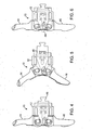
- the arms 14, 16 are rotationally movable between at least an undeployed, collapsed or folded state (as shown in FIGs. 1a-1e ) and at least a fully deployed state (as shown in FIGs. 4 ).
- FIG. 5 One of many partially deployed states through which the arms move between the fully undeployed and fully deployed state is shown in FIG. 5 .
- the arm pairs 14, 16 are aligned generally or substantially axially (i.e., axially with the longitudinal axis defined by the body 12 or to the translation path into the interspinous space of the patient) to provide a minimal lateral or radial profile.
- the longitudinal axis X of the body is shown in FIG. 1c .
- the arm pairs 14, 16 are positioned such that the U-shaped saddles are in a plane or have a U-shaped projection in a plane that is generally or substantially transverse to the longitudinal axis X defined by the body 12 or to the collapsed position or to the translation path into the interspinous space of the patient.
- the arms 14, 16 may also be linearly moveable or translatable within the plane from a first deployed state to and from a second deployed state characterized by an additional extension of at least one of the arms 14, 16 along the direction of the arrows as shown in FIG. 6 . More specifically, the arms 14, 16 can be extended in the general vertical direction along an axis substantially parallel to the spine wherein the arms 14, 16 are extended away from each other and away from the body 12 as denoted by the arrows in FIG. 6 .
- This feature advantageously allows for the most minimally invasive configuration for the spacer without compromising the ability to seat and contain the spinous processes in between levels where the process anatomy in such that the interspinous process space increases in the anterior direction or without compromising the ability of the spacer to provide adequate distraction.
- the arms 14, 16 are connected to the body 12 and/or to each other in a manner that enables them to be moved simultaneously or independently of each other, as well as in a manner that provides passive deployment and/or vertical extension or, alternatively, active or actuated deployment and/or vertical extension.
- the actuator assembly 18 includes an actuator 48 connected to a shaft 50.
- the actuator 48 includes a distal end 54 and a proximal end 56 and at least two bearing surfaces 58.
- the bearing surfaces 58 angle towards each other from the proximal end 54 to the distal end 56.
- the shaft 50 has a substantially reduced cross-sectional area and includes a neck 60 for connection with a spacer insertion instrument.
- the actuator assembly is at least partially disposed inside the body and is configured for sliding engagement with respect to the body.
- the actuator 48 includes a slot 61 for receiving an actuator pin 52 seen in FIG. 1d that is connected to the body.
- the actuator 48 with the pin 52 passed through the slot 61, is connected to the body in sliding engagement.
- the distal end of the actuator shaft is further configured to engage the superior and inferior arms 14, 16 such that forward translation of the actuator relative to the body effects deployment of the arms into at least one deployed configuration.
- the at least one deployed configuration can be selectively locked into position via the actuator pin 52 riding inside the slot in the actuator shaft and engaging several fingers 75 forming one or more constrictions along the slot path.
- the constrictions are configured to lock the pin 52 keeping it fixed in at least one desired deployed configuration in a friction fit engagement.
- Four sets of fingers 75 grouped in two sets of two oppositely located sets of fingers 75 are shown in FIG. 7b and are configured such that the pin 52 is capable of entering two locked locations between the sets of fingers 75.
- a first locked location locks the arms in a deployed configuration and the second locked location locks the arms in an extended-deployed location wherein the pin 52 is resident between two oppositely located sets of fingers when in the at least one locked location.
- the fingers 75 flex to corral the pin in place.
- the actuator 48 includes an actuator 48 connected to a shaft 50.
- the actuator assembly includes a distal end 54 and a proximal end 56 and at least two bearing surfaces 58.
- the bearing surfaces 58 angle towards each other from the proximal end 54 to the distal end 56.
- the shaft 50 has a substantially reduced cross-sectional area and includes a neck 60 for connection with a spacer insertion instrument.
- the actuator includes several fingers 75 forming one or more constrictions along the slot 61 path. The constrictions are configured to lock the pin 52 keeping it fixed in at least one desired deployed configuration in a friction fit engagement.
- One set of fingers 75 are shown in FIG. 8 and are configured such that the pin 52 is pressed in the fingers when in one deployed configuration.
- the spacer 10 includes a body 12, a superior extension member or arm 14, an inferior extension member or arm 16, and an actuator assembly 18.
- the body 12 is shown to have a one-piece construction; however, the body 12 may be configured into a clamshell with two mating pieces joined together as described above.
- the body 12 has a cross-sectional size and shape that allows for implantation between adjacent spinous processes and facilitates delivery into a patient through a narrow port or cannula.
- the inside of the body 12 defines an arm receiving portion 24 and an actuator assembly receiving portion 26 with features formed therein that together define the arm and actuator assembly receiving portions 24, 26.
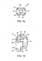
- the arm receiving portion 24 includes slots 28 that receive one or more pins to capture the arms 14, 16 such that the arms can hinge about the pin. As shown in FIG. 10 , the slots 28 are formed in flange-like extensions of the body.
- the actuator assembly receiving portion 26 includes a passageway 30 that conforms to the shape of the actuator.
- the outside of the body 12 defines a ledge 32 along at least a portion of the periphery.
- Notches 34 are formed with the ledge 32 at opposite locations.
- the notches 34 are configured for pronged attachment to a spacer delivery instrument such that a portion of the spacer delivery instrument securely connects with the body.
- the body 12 defines a proximal opening 36 and a distal opening 38.
- a longitudinal scallop 78 extending from the proximal end of the spacer to the distal end on either one or both sides and oppositely located, is formed to facilitate placement of the spacer 10 between and to conform to the anatomy of adjacent interspinous processes.
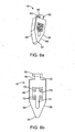
- the longitudinal scallops 78 are also shown in FIGs. 9a and 9e .
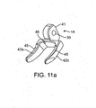
- the superior and inferior arms 14, 16 include apertures 39 for receiving a pin for pinned connection and rotation with respect to the body 12.
- Each of the superior and inferior arms 14, 16 includes at least one camming surface 41, 43, respectively, for contact with the actuator assembly 18.
- the superior and inferior arms 14, 16 include elongated superior extensions 42a, 42b and elongated inferior extensions 44a, 44b, respectively. Extensions 42a and 44a are located on one side of the body and extensions 42b and 44b are located on the other side of the body. Superior extensions 42a, 42b extend substantially parallel to each other in both an undeployed configuration and in a deployed configuration as do inferior extensions 44a, 44b.
- Extending between extensions 42a, 42b is a strut, bridge, bracket or saddle 46 that forms a superior substantially U-shaped configuration together with the extensions 42a, 42b that is sized and configured to receive and seat or contain at least a portion a superior spinous process.
- the anterior deployed face of the superior extensions 14 includes a slight concavity 45 for conforming to the bony anatomy of the superior spinous process and or lamina.
- the anterior deployed face of the inferior extensions 16 includes a slight convexity 47 for conforming to the bony anatomy of the inferior spinous process and or lamina.
- Extending between inferior extensions 44a, 44b is a strut, bridge, bracket or saddle 48 that forms an inferior substantially U-shaped configuration together with the extensions 44a, 44b that is sized and configured to receive and seat at least a portion of an inferior spinous process of a spinal motion segment.
- the superior and inferior arms 14, 16 are movably or rotatably connected to the body 12, for example by a pin or hinge means or the like to provide rotational movement to and from an undeployed configuration to a deployed configuration that arcs through approximately a 90 degree range or more.
- the arms 14, 16 are rotationally movable between at least an undeployed, collapsed or folded state (as shown in FIGs. 9a-9e ) and at least a fully deployed state (as shown in FIGs. 4 and 6 ).
- a partially deployed state through which the arms move between the undeployed and deployed state is shown in FIG. 5 .
- the arm pairs 14, 16 are aligned generally or substantially axially (i.e., axially with the longitudinal axis defined by the body 12 or to the translation path into the interspinous space of the patient) to provide a minimal lateral or radial profile.
- the longitudinal axis X of the body is shown in FIG. 9c .
- the arm pairs 14, 16 are positioned in a plane generally or substantially transverse to the collapsed position (i.e., in a plane transverse to the longitudinal axis X defined by the body 12 or to the translation path into the interspinous space of the patient).
- the arms 14, 16 are connected to the body 12 and/or to each other in a manner that enables them to be moved simultaneously or independently of each other, as well as in a manner that provides passive deployment and/or vertical extension or, alternatively, active or actuated deployment and/or vertical extension.
- the actuator assembly 18 includes an actuator 48 connected to a shaft 50.
- the actuator 48 includes a distal end 54 and a proximal end 56 and at least two bearing surfaces 58.
- the bearing surfaces 58 angle away from each other from the proximal end 54 to the distal end 56. Furthermore, the bearing surfaces are displaced laterally from each other.
- the shaft 50 has a substantially reduced cross-sectional area forming a neck or receiving portion 60 for connection with a spacer insertion instrument.
- the actuator assembly 18 is at least partially disposed inside the body and is configured for sliding engagement with respect to the body.
- the actuator 48 includes a slot 61 for receiving an actuator pin 52 seen in FIG.
- the actuator 48 with the pin 52 passed through the slot 61, is connected to the body in sliding engagement.
- the distal end 54 of the actuator 48 is further configured to engage the superior and inferior arms 14, 16 such that forward translation of the actuator relative to the body 12 effects deployment of the arms 14, 16 into at least one deployed configuration.
- the at least one deployed configuration can be selectively locked into position via the actuator pin 52 riding inside the slot in the actuator shaft and engaging several fingers 75 forming one or more constrictions along the slot path.
- the constrictions are configured to lock the pin 52 keeping it and the deployed arms fixed in at least one desired deployed configuration in a friction fit engagement.
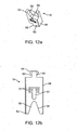
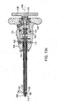
- One set of fingers 75 is shown in FIG. 12b which is configured such that the pin 52 is resident between the fingers when in one deployed configuration.
- the arms 14, 16 are disposed in the arm receiving portion 24 of one body piece.
- the other of the left or right body piece 20, 22 is securely connected/welded to the one body piece thereby capturing the arms 14, 16 inside the arm receiving portion 24 such that the arms 14, 16 are capable of at least rotational movement with respect to the body 12 and in one variation, capable of rotational movement and translation with respect to the body 12.
- the arms 14, 16 are movably connected to the body 12 with a pin.
- the actuator assembly 18 is inserted into the passageway 30 of the body 12 and a pin 52 is passed through the body 12 and into the slot 61 of the actuator 48 securing the actuator assembly 18 to the body 12 such that the actuator 48 is allowed to slide with respect to the body 12.
- the spacer 10 is releasably attached to a delivery instrument at the proximal end of the spacer 10 via notches 34.
- the delivery instrument will now be described in greater detail.
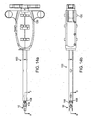
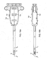
- the insertion instrument 100 includes a first subassembly 102, a second subassembly 104 and a third subassembly 105 connected to a handle assembly 106.
- the first subassembly 102 is configured to releasably clamp to the body 12 of the spacer 10 at a distal end 108 of the insertion instrument. Still referencing FIGs. 13a-13c , the first subassembly 102 includes a first clamp shaft 110 and a first outer shaft 112 configured for relative motion with respect to one another via a first control 114 located at the handle assembly 106. With particular reference to FIG. 13c , the first control 114 is threaded to the first outer shaft 112 such that rotation of the first control 114 moves the first outer shaft 112 along the longitudinal axis 116 of the insertion instrument 100. Reverse rotation of the first control 114 reverses the direction of translation of the first outer shaft 112.
- the first clamp shaft 110 is shown in FIG. 13d .
- the first clamp shaft 110 is a cannulated shaft fixed to the handle assembly 106 and configured to be received inside the cannulated first outer shaft 112.
- the first clamp shaft 110 includes two oppositely located, outwardly splayed prongs 118 that are permitted to flex inwardly and return to their outwardly splayed normal position as shown in FIG. 13d when released.
- the prongs 118 are configured to be clamped into the notches 34 formed in the spacer body 12 to clamp onto and securely hold the spacer 10 to the insertion instrument 100.
- the first outer shaft 112 As the first outer shaft 112 is translated distally in sliding motion with respect to the first clamp shaft 110 by rotating the first control 114 in one direction, the first outer shaft 112 is configured to advance over the outwardly splayed prongs 118 and deflect them inwardly to clamp into a properly oriented, juxataposed spacer body 12.
- the first outer shaft 112 When the first outer shaft 112 is translated proximally with respect to the first clamp shaft 110 by rotating the first control in an opposite direction, the first outer shaft 112 is configured to uncover the prongs 118 allowing them to flex outwardly to their normal outwardly splayed configuration to release a spacer 10 to which it is connected.
- the second subassembly 104 is configured to releasably clamp to the actuator 48 of the spacer 10 at the distal end 108 of the insertion instrument 100.
- the second subassembly 104 includes a second clamp shaft 120 and a second outer shaft 122 configured for relative motion with respect to one another via a second control 124 located at the handle assembly 106.
- the second control 124 is threaded to the second outer shaft 122 such that rotation of the second control 124 moves the second outer shaft 122 along the longitudinal axis 116 of the insertion instrument 100. Reverse rotation of the second control 124 reverses the direction of translation of the second outer shaft 122.
- the second clamp shaft 120 is shown in FIG.
- the second clamp shaft 120 is a connected to the third subassembly 105 and configured to be received inside the cannulated second outer shaft 122. Both the second clamp shaft 120 and the second outer shaft 122 are located concentrically inside the first clamp shaft 110.
- the second subassembly 104 is located concentrically inside the first subassembly 102.
- the second clamp shaft 120 includes two oppositely located, outwardly splayed prongs 126 that are permitted to flex inwardly and return to their outwardly splayed normal position.
- the prongs 126 are configured to be clamped to the actuator 48 of the spacer 10, and in particular, to the proximal end 56 of the actuator 48 at the neck receiving portion 60 of the actuator shaft 50. Any suitable interface may be formed for connecting to the actuator 48.
- the second outer shaft 122 is translated distally with respect to the second clamp shaft 120 by rotating the second control 124 in one direction, the second outer shaft 112 is configured to advance over the outwardly splayed prongs 126 and deflect them inwardly to connect to the actuator 48 of a juxataposed spacer 10.
- the second outer shaft 122 When the second outer shaft 122 is translated proximally with respect to the second clamp shaft 120 by rotating the second control 124 in an opposite direction, the second outer shaft 122 is configured to uncover the prongs 126 allowing them to flex outwardly to their normal outwardly splayed configuration to release the actuator 48 of the spacer 10 to which it is connected.
- the third subassembly 105 is configured to translate the entire second subassembly 104 with respect to the handle assembly 106 (or, in another variation, with respect to the first subassembly 102) to thereby translate the actuator 48 of a spacer 10 with respect to the body 12 of the spacer to arrange the spacer to and from deployed and undeployed configurations.
- the third subassembly 105 includes a proximally located third control 128 configured in the form of a removable drive handle threaded to the second assembly 104 and configured for effecting relative motion of the second assembly 104 with respect to the handle assembly 106 wherein rotation of the drive handle 128 moves the second assembly 104 along the longitudinal axis 116 of the insertion instrument 100.
- the third assembly 105 further includes a fourth control 130 for adjusting the position of the second assembly 104 relative to the handle assembly 106 such that differently-sized spacers are easily connectable to the insertion instrument at the distal end.
- a setting of large L on the fourth control 130 positions the second assembly 104 proximally with respect to the handle assembly 106 such that a spacer with a longitudinally longer body 12 may be easily accepted and connected to the insertion instrument 100 at the distal end 108.
- a setting of small S on the fourth control 130 positions the second assembly 104 distally with respect to the handle assembly 106 such that a spacer with a longitudinally shorter body 12 may be easily accepted and connected to the insertion instrument 100 at the distal end 108.
- the fourth control 130 may also be employed simultaneously or independently of the third control 128 to arrange the spacer to and from deployed and undeployed configurations.
- insertion instrument 100 may be a lock 132 configured to lock the first and second subassemblies 102, 104 into position to prevent accidental release of the spacer body 12 or spacer actuator 12.
- a direction indicator 134 may be provided on the instrument 100 for orientating the instrument 100 with respect to the patient anatomy. In one variation, for example, the direction indicator 134 indicates a cephalad orientation.
- Various depth markings 136 may also be provided as well as connection arrows for lining up the spacer with respect to the instrument.
- the fourth control 130 is adjusted for the size of spacer 10 to be connected to the insertion instrument 100. If a longitudinally large spacer 10 is to be connected, the fourth control 130 is set to large. If a longitudinally small spacer 10 is to be connected, the fourth control 130 is set to small. This selection positions the distal end of the second assembly 104 proximally or distally with respect to the distal end 108 of the instrument 10 for attachment to the actuator 48. The spacer 10 is then positioned proximate to the distal end 108 of the insertion instrument 100. The spacer 10 is provided or otherwise placed in its undeployed state next to the distal end 108 of the instrument. Initially, the prongs 118, 126 are not engaged as shown in FIGs. 14a-14d .
- the first control 114 is activated at the handle of the insertion instrument 100 such that the first subassembly 102 is connected to the body 12 of the spacer 10.
- the first control 114 is rotated in one direction to advance the first outer shaft 112 over the first clamp shaft 110 deflecting the prongs 118 inwardly into the notches 34 on the body of the spacer 12 to secure the spacer body 12 to the instrument as shown clearly in FIG. 15c.
- FIG. 15d shows that the prongs 126 of the second subassembly 104 are not connected to the actuator 48.
- the second control 124 is activated at the handle of the insertion instrument such that the second subassembly is connected to the actuator 48 of the spacer 10.
- the second control 124 is rotated in one direction to advance the second outer shaft 122 over the second clamp shaft 120 deflecting the prongs 126 inwardly to clarrip onto the proximal end 56 of the actuator shaft 50 to secure the actuator 48 to the instrument 100 as shown clearly in FIG. 16d .
- the instrument 100 may be employed such that the second subassembly 104 is connected first to the actuator and then the first subassembly 102 is connected to the body.
- the lock 132 is pushed to lock the first and second subassemblies 102, 104 in place to prevent accidental detachment.
- the spacer 10 is releasably attached to a delivery instrument 100 at the proximal end of the spacer 10 as described.
- a small midline or lateral-to-midline incision is made in the patient for minimally-invasive percutaneous delivery.
- the supraspinous ligament is split longitudinally along the direction of the tissue fibers to create an opening for the instrument. Dilators may be further employed to create the opening.
- the spacer 10 In the undeployed state with the arms 14, 16 in a closed orientation and attached to a delivery instrument, the spacer 10 is inserted into a port or cannula, if one is employed, which has been operatively positioned in an interspinous space within a patient's back and the spacer is passed through the cannula to the interspinous space between two adjacent vertebral bodies. The spacer 10 is advanced beyond the end of the cannula or, alternatively, the cannula is pulled proximately to uncover the spacer 10 connected to the instrument 100. Once in position, the third control 128 and/or fourth control 130 is rotated to begin the deployment of at least one of the superior arm 14 and inferior arm 16 or both simultaneously. FIGs.
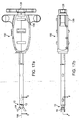
- FIGs. 17a-17d illustrate the superior arm 14 and the inferior arm 16 in a partially deployed position with the arms 14,16 rotated away from the longitudinal axis 116 and the second subassembly 104 advanced distally with respect to the body of the spacer 12.
- Distal advancement of the second subassembly 104 which is connected to the actuator 48 in turn, distally advances the actuator 48 whose bearing surfaces 58 contact the superior and inferior camming surfaces 41, 43 pushing the superior and inferior arms 14, 16 into rotation about the pins 40.
- the position of the arms 14, 16 in FIGs. 17a-17d may be considered to be one of many partially deployed configurations that are possible and from which the deployment of the arms 14, 16 is reversible with opposite rotation of the third and/or fourth controls 128, 130.
- FIGs. 18a-18d there is shown an insertion instrument 100 connected to a spacer 10 in a first deployed configuration in which the arms 14, 16 are approximately 90 degrees perpendicular to longitudinal axis 116 or perpendicular the initial undeployed configuration.
- the clinician can observe with fluoroscopy the positioning of the spacer 10 inside the patient and then choose to reposition the spacer if desired.
- Repositioning of the spacer may involve undeploying the arms 14, 16 rotating them into any one of the many undeployed configurations. The spacer may then be re-deployed into the desired location. This process can be repeated as necessary until the clinician has achieved the desired positioning of the spacer in the patient.
- the second deployed configuration is an extended configuration in which the superior and inferior arms 14, 16 extend transversely with respect to the longitudinal axis 116 outwardly in the direction of the arrows in FIG. 19 .
- Such extension is guided by the length and shape of the slots 28 in which the arms 14, 16 move.
- the superior arm 14 seats the superior spinous process and the inferior arm 16 seats the adjacent inferior spinous process.
- Such extension may also provide some distraction of the vertebral bodies.
- the actuator pin 52 is seated between the fingers 75 and locked therein.
- the lock 132 is released to permit rotation of the first and second controls 114, 124 which are rotated in the opposite direction to release the body 12 and the actuator 48 from the instrument 100, respectively.
- the insertion instrument 100 thus released from the spacer, is removed from the patient leaving the spacer 10 implanted in the interspinous process space as shown in FIG. 20 .
- the spacer 10 is shown with the superior arm 14 seating the superior spinous process 138 of a first vertebral body 142 and the inferior arm 16 seating the inferior spinous process 140 of an adjacent second vertebral body 144 providing sufficient distraction to open the neural foramen 146 to relieve pain.
- the shape of the superior arm 14 is such that a superior concavity or curvature 45 is provided to conform to the widening of the superior spinous process 138 in an anterior direction toward the superior lamina 148 going in the anterior direction.
- the superior arm 14 is shaped to conform to anatomy in the location in which it is seated.
- the shape of the inferior arm 16 is such that an inferior convexity or curvature 47 is provided to conform to the widening of the inferior spinous process 140 in an anterior direction toward the inferior lamina 150.
- the supraspinous ligament 152 is also shown in FIG. 20 .
- any of the spacers disclosed herein are configured for implantation employing minimally invasive techniques including through a small percutaneous incision and may or may not be through the supraspinous ligament.
- Implantation through the supraspinous ligament involves selective dissection of the supraspinous ligament in which the fibers of the ligament are separated or spread apart from each other in a manner to maintain as much of the ligament intact as possible. This approach avoids crosswise dissection or cutting of the ligament and thereby reduces the healing time and minimizes the amount of instability to the affected spinal segment. While this approach is ideally suited to be performed through a posterior or midline incision, the approach may also be performed through one or more incisions made laterally of the spine with or without affect to the supraspinous ligament.
- the spacer may also be implanted in a lateral approach that circumvents the supraspinous ligament altogether.
- a spacer may include only a single arm which is configured to receive either the superior spinous process or the inferior spinous process.
- the surface of the spacer body opposite the side of the single arm may be contoured or otherwise configured to engage the opposing spinous process wherein the spacer is sized to be securely positioned in the interspinous space and provide the desired distraction of the spinous processes defining such space.
- the additional extension of the arm(s) subsequent to their initial deployment in order to seat or to effect the desired distraction between the vertebrae may be accomplished by expanding the body portion of the device instead of or in addition to extending the individual extension members 14, 16.
- the spacer is configured such that arms are bifurcated side-to-side, instead of top-to-bottom for independent lateral deployment.
- the spacer includes a left arm and a right arm, instead of a superior arm and an inferior arm.
- the right arm includes extensions 42a and 44a and the left arm includes extensions 42b and 44b wherein extensions 42a and 44b are deployed independently of extension 42b, 44b on the other side of the spacer.
- This variation allows for the spacer to be inserted in the same manner as described above and one arm is deployed on one side of the both the superior and inferior spinous processes and the second arm is subsequently deployed on the other side of both the superior and inferior spinous processes.
- the extension arms of the subject device may be configured to be selectively movable subsequent to implantation, either to a fixed position prior to closure of the access site or otherwise enabled or allowed to move in response to normal spinal motion exerted on the device after deployment.
- the deployment angles of the extension arms may range from less than 90 degrees (relative to the longitudinal axis defined by the device body) or may extend beyond 90 degrees.
- Each extension member may be rotationally movable within a range that is different from that of the other extension members.
- the individual superior and/or inferior extensions 42a, 42b, 44a, 44b may be movable in any direction relative to the strut or bridge extending between an arm pair or relative to the device body in order to provide shock absorption and/or function as a motion limiter, or serve as a lateral adjustment particularly during lateral bending and axial rotation of the spine.
- the manner of attachment or affixation of the extensions to the arms may be selected so as to provide movement of the extensions that is passive or active or both.
- the saddle or distance between extensions 42a and 42b or between 44a and 44b can be made wider to assist in seating the spinous process and then narrowed to secure the spinous process positioned between extensions 42a and 42b or between 44a and 44b.
Landscapes
- Health & Medical Sciences (AREA)
- Orthopedic Medicine & Surgery (AREA)
- Life Sciences & Earth Sciences (AREA)
- Neurology (AREA)
- Surgery (AREA)
- Heart & Thoracic Surgery (AREA)
- Engineering & Computer Science (AREA)
- Biomedical Technology (AREA)
- Nuclear Medicine, Radiotherapy & Molecular Imaging (AREA)
- Medical Informatics (AREA)
- Molecular Biology (AREA)
- Animal Behavior & Ethology (AREA)
- General Health & Medical Sciences (AREA)
- Public Health (AREA)
- Veterinary Medicine (AREA)
- Prostheses (AREA)
Claims (15)
- Écarteur implantable (10) destiné à être mis en place entre des processus interépineux adjacents dans un segment vertébral mobile comprenant :un corps (12) définissant un passage longitudinal et un axe longitudinal ;un premier bras (14) et un second bras (16) connectés au corps et capables de pivoter par rapport au corps ; chaque bras ayant une paire d'extensions et étant conçu de manière à ce qu'un processus épineux soit contenu entre la paire d'extensions ; chaque bras ayant une surface de came proximale (41, 43) ;un ensemble actionneur (18) connecté au corps ; l'ensemble actionneur comprenant un actionneur (48) ayant une extrémité proximale et une extrémité distale ; l'actionneur ayant au moins une surface d'appui à l'extrémité distale conçue pour venir au contact de chaque surface de came ; l'actionneur étant connecté au corps et conçu pour se déplacer à l'intérieur du passage longitudinal par rapport au corps pour entrer en contact avec chaque surface de came avec l'au moins une surface d'appui et déplacer ainsi les bras d'une configuration non déployée dans laquelle les bras sont essentiellement parallèles à l'axe longitudinal du corps à une configuration déployée dans laquelle les bras sont essentiellement perpendiculaires à l'axe longitudinal du corps de manière à contenir des processus épineux adjacents dans chaque bras lorsqu'ils sont dans la configuration déployée, l'actionneur comprenant deux surfaces d'appui (58) qui convergent vers l'extrémité distale de l'actionneur.
- Écarteur selon la revendication 1, dans lequel les bras sont conçus pour pivoter par rapport au corps lors du déplacement d'une configuration non déployée à une configuration déployée, en particulier dans lequel les bras sont conçus pour pivoter par rapport au corps par rapport à un seul axe lors du déplacement d'une configuration non déployée à une configuration déployée.
- Écarteur selon la revendication 1, dans lequel chaque bras est conçu pour pivoter par rapport au corps par rapport à des axes séparés.
- Écarteur selon la revendication 1, dans lequel les bras sont conçus pour pivoter par rapport au corps lors du déplacement d'une configuration non déployée à une première configuration déployée, puis à se déplacer par translation par rapport au corps lors du déplacement de la première configuration déployée à une seconde configuration déployée, en particulier dans lequel la rotation est d'environ 90 degrés de la configuration non déployée à la première configuration déployée.
- Écarteur selon la revendication 4, dans lequel chaque bras est conçu pour pivoter vers l'extérieur dans un espace plan essentiellement transversal à l'axe longitudinal ; et chaque bras est conçu pour se déplacer par translation dans ledit plan à partir de l'axe longitudinal lors du déplacement de la première configuration déployée à une seconde configuration déployée.
- Écarteur selon la revendication 1, dans lequel l'actionneur comprend une rainure allongée (61) et l'actionneur est connecté au corps avec une broche (52) passée à travers la rainure et connectée au corps, l'actionneur étant ainsi conçu pour se déplacer longitudinalement par rapport au corps.
- Écarteur selon la revendication 6, dans lequel la rainure allongée comprend au moins un rétrécissement conçu pour bloquer la broche par rapport à l'actionneur quand les bras sont positionnés dans au moins une configuration déployée.
- Écarteur selon la revendication 1, dans lequel le premier bras est conçu pour contenir un processus épineux supérieur, et le second bras est conçu pour contenir un processus épineux inférieur.
- Écarteur selon la revendication 1, dans lequel le premier bras est conçu pour contenir un côté des processus épineux supérieur et inférieur, et le second bras est conçu pour contenir l'autre côté des processus épineux supérieur et inférieur.
- Écarteur selon la revendication 1, dans lequel le corps comprend au moins une coquille longitudinale s'étendant le long d'au moins une partie du corps ; la coquille étant conçue pour fournir un profil inférieur à l'écarteur en vue son insertion entre des processus interépineux adjacents le long d'une approche médiane postérieure dans la configuration non déployée par rapport à l'au moins une configuration déployée.
- Instrument d'insertion conçu pour apporter un écarteur selon l'une quelconque des revendications 1 à 10 dans un espace de processus interépineux d'un patient, et pour déployer l'écarteur d'une configuration non déployée à au moins une configuration déployée afin de soulager une douleur ; l'instrument d'insertion (100) comprenant :un ensemble poignée (106) ;un premier ensemble (102) connecté à l'ensemble poignée, le premier ensemble étant conçu pour se connecter au corps de l'écarteur au niveau de l'extrémité distale de l'instrument d'insertion, le premier ensemble ayant une première commande au niveau de l'ensemble poignée conçue pour connecter et libérer le corps de l'écarteur et le premier ensemble ;un deuxième ensemble (104) connecté à l'ensemble poignée, le deuxième ensemble étant conçu pour se connecter à l'extrémité proximale de l'actionneur de l'écarteur au niveau de l'extrémité distale de l'instrument d'insertion, le deuxième ensemble ayant une seconde commande au niveau de l'ensemble poignée conçue pour connecter et libérer l'actionneur et le deuxième ensemble ; etun troisième ensemble (105) connecté à l'ensemble poignée ; le troisième ensemble étant conçu pour déplacer le deuxième ensemble par rapport au corps de l'écarteur afin de configurer l'écarteur d'une configuration non déployée à au moins une configuration déployée.
- Instrument d'insertion selon la revendication 11, dans lequel le premier ensemble comprend :un premier arbre extérieur (112) ;un premier arbre de serrage (110) connecté au premier arbre extérieur et situé concentriquement à l'intérieur du premier arbre extérieur ; le premier arbre de serrage ayant deux premières griffes conçues pour se plier et se connecter au corps de l'écarteur ;dans lequel le premier arbre extérieur est conçu pour se déplacer par rapport au premier arbre de serrage de telle sorte que le déplacement distal du premier arbre extérieur par rapport au premier arbre de serrage déplace les premières griffes vers l'intérieur de manière à les connecter au corps de l'écarteur, et de telle sorte que le déplacement proximal du premier arbre extérieur par rapport au premier arbre de serrage découvre les premières griffes de manière à les écarter vers l'extérieur dans leur position normale afin de libérer le corps de l'écarteur.
- Instrument d'insertion selon la revendication 11, dans lequel le deuxième ensemble comprend :un second arbre extérieur (122) ;un second arbre de serrage (120) connecté au second arbre extérieur et situé concentriquement à l'intérieur du second arbre extérieur ; le second arbre de serrage ayant deux secondes griffes (126) conçues pour se plier et se connecter à l'actionneur de l'écarteur ;dans lequel le second arbre extérieur est conçu pour se déplacer par rapport au second arbre de serrage de telle sorte que le déplacement distal du second arbre extérieur par rapport au second arbre de serrage déplace les secondes griffes vers l'intérieur de manière à les connecter à l'actionneur de l'écarteur, et de telle sorte que le déplacement proximal du second arbre extérieur par rapport au second arbre de serrage découvre les secondes griffes de manière à les écarter vers l'extérieur dans leur position normale afin de libérer l'actionneur de l'écarteur.
- Instrument d'insertion selon la revendication 11, dans lequel le second ensemble est situé concentriquement à l'intérieur du premier ensemble.
- Écarteur selon la revendication 1, dans lequel l'extrémité proximale de l'actionneur est conçue pour permettre la fixation d'un instrument selon l'une quelconque des revendications 11 à 14 afin de déplacer l'actionneur par rapport au corps.
Applications Claiming Priority (3)
| Application Number | Priority Date | Filing Date | Title |
|---|---|---|---|
| US92384107P | 2007-04-16 | 2007-04-16 | |
| US92397107P | 2007-04-17 | 2007-04-17 | |
| PCT/US2008/004901 WO2008130564A1 (fr) | 2007-04-16 | 2008-04-16 | Espaceur interspinal |
Publications (3)
| Publication Number | Publication Date |
|---|---|
| EP2155121A1 EP2155121A1 (fr) | 2010-02-24 |
| EP2155121A4 EP2155121A4 (fr) | 2012-08-01 |
| EP2155121B1 true EP2155121B1 (fr) | 2015-06-17 |
Family
ID=39875803
Family Applications (1)
| Application Number | Title | Priority Date | Filing Date |
|---|---|---|---|
| EP08742949.4A Active EP2155121B1 (fr) | 2007-04-16 | 2008-04-16 | Espaceur interspinal |
Country Status (6)
| Country | Link |
|---|---|
| US (4) | US8292922B2 (fr) |
| EP (1) | EP2155121B1 (fr) |
| AU (2) | AU2008241447B2 (fr) |
| CA (1) | CA2684461C (fr) |
| IL (1) | IL201538A0 (fr) |
| WO (1) | WO2008130564A1 (fr) |
Families Citing this family (114)
| Publication number | Priority date | Publication date | Assignee | Title |
|---|---|---|---|---|
| US7959652B2 (en) | 2005-04-18 | 2011-06-14 | Kyphon Sarl | Interspinous process implant having deployable wings and method of implantation |
| US20080039859A1 (en) | 1997-01-02 | 2008-02-14 | Zucherman James F | Spine distraction implant and method |
| US20080086212A1 (en) | 1997-01-02 | 2008-04-10 | St. Francis Medical Technologies, Inc. | Spine distraction implant |
| US6068630A (en) | 1997-01-02 | 2000-05-30 | St. Francis Medical Technologies, Inc. | Spine distraction implant |
| US8147548B2 (en) | 2005-03-21 | 2012-04-03 | Kyphon Sarl | Interspinous process implant having a thread-shaped wing and method of implantation |
| US8221463B2 (en) | 2002-10-29 | 2012-07-17 | Kyphon Sarl | Interspinous process implants and methods of use |
| US7549999B2 (en) | 2003-05-22 | 2009-06-23 | Kyphon Sarl | Interspinous process distraction implant and method of implantation |
| US8048117B2 (en) | 2003-05-22 | 2011-11-01 | Kyphon Sarl | Interspinous process implant and method of implantation |
| US8128662B2 (en) | 2004-10-20 | 2012-03-06 | Vertiflex, Inc. | Minimally invasive tooling for delivery of interspinous spacer |
| US8123782B2 (en) | 2004-10-20 | 2012-02-28 | Vertiflex, Inc. | Interspinous spacer |
| US8123807B2 (en) | 2004-10-20 | 2012-02-28 | Vertiflex, Inc. | Systems and methods for posterior dynamic stabilization of the spine |
| US8167944B2 (en) | 2004-10-20 | 2012-05-01 | The Board Of Trustees Of The Leland Stanford Junior University | Systems and methods for posterior dynamic stabilization of the spine |
| US9023084B2 (en) | 2004-10-20 | 2015-05-05 | The Board Of Trustees Of The Leland Stanford Junior University | Systems and methods for stabilizing the motion or adjusting the position of the spine |
| US8277488B2 (en) | 2004-10-20 | 2012-10-02 | Vertiflex, Inc. | Interspinous spacer |
| US8409282B2 (en) | 2004-10-20 | 2013-04-02 | Vertiflex, Inc. | Systems and methods for posterior dynamic stabilization of the spine |
| US9161783B2 (en) | 2004-10-20 | 2015-10-20 | Vertiflex, Inc. | Interspinous spacer |
| WO2009009049A2 (fr) | 2004-10-20 | 2009-01-15 | Vertiflex, Inc. | Espaceur interépineux |
| US8152837B2 (en) | 2004-10-20 | 2012-04-10 | The Board Of Trustees Of The Leland Stanford Junior University | Systems and methods for posterior dynamic stabilization of the spine |
| US7763074B2 (en) | 2004-10-20 | 2010-07-27 | The Board Of Trustees Of The Leland Stanford Junior University | Systems and methods for posterior dynamic stabilization of the spine |
| US8613747B2 (en) | 2004-10-20 | 2013-12-24 | Vertiflex, Inc. | Spacer insertion instrument |
| US9119680B2 (en) | 2004-10-20 | 2015-09-01 | Vertiflex, Inc. | Interspinous spacer |
| US8425559B2 (en) | 2004-10-20 | 2013-04-23 | Vertiflex, Inc. | Systems and methods for posterior dynamic stabilization of the spine |
| US8012207B2 (en) | 2004-10-20 | 2011-09-06 | Vertiflex, Inc. | Systems and methods for posterior dynamic stabilization of the spine |
| US8864828B2 (en) | 2004-10-20 | 2014-10-21 | Vertiflex, Inc. | Interspinous spacer |
| US8317864B2 (en) | 2004-10-20 | 2012-11-27 | The Board Of Trustees Of The Leland Stanford Junior University | Systems and methods for posterior dynamic stabilization of the spine |
| US8945183B2 (en) | 2004-10-20 | 2015-02-03 | Vertiflex, Inc. | Interspinous process spacer instrument system with deployment indicator |
| US8241330B2 (en) | 2007-01-11 | 2012-08-14 | Lanx, Inc. | Spinous process implants and associated methods |
| US9055981B2 (en) | 2004-10-25 | 2015-06-16 | Lanx, Inc. | Spinal implants and methods |
| ATE524121T1 (de) | 2004-11-24 | 2011-09-15 | Abdou Samy | Vorrichtungen zur platzierung eines orthopädischen intervertebralen implantats |
| EP2219538B1 (fr) | 2004-12-06 | 2022-07-06 | Vertiflex, Inc. | Instrument d'insertion d'un écarteur |
| US8100943B2 (en) | 2005-02-17 | 2012-01-24 | Kyphon Sarl | Percutaneous spinal implants and methods |
| US8097018B2 (en) | 2005-02-17 | 2012-01-17 | Kyphon Sarl | Percutaneous spinal implants and methods |
| US8029549B2 (en) * | 2005-02-17 | 2011-10-04 | Kyphon Sarl | Percutaneous spinal implants and methods |
| US8096995B2 (en) | 2005-02-17 | 2012-01-17 | Kyphon Sarl | Percutaneous spinal implants and methods |
| US8034080B2 (en) | 2005-02-17 | 2011-10-11 | Kyphon Sarl | Percutaneous spinal implants and methods |
| US8029567B2 (en) | 2005-02-17 | 2011-10-04 | Kyphon Sarl | Percutaneous spinal implants and methods |
| US8038698B2 (en) | 2005-02-17 | 2011-10-18 | Kphon Sarl | Percutaneous spinal implants and methods |
| US20070276493A1 (en) | 2005-02-17 | 2007-11-29 | Malandain Hugues F | Percutaneous spinal implants and methods |
| US8096994B2 (en) | 2005-02-17 | 2012-01-17 | Kyphon Sarl | Percutaneous spinal implants and methods |
| US8157841B2 (en) | 2005-02-17 | 2012-04-17 | Kyphon Sarl | Percutaneous spinal implants and methods |
| US8007521B2 (en) | 2005-02-17 | 2011-08-30 | Kyphon Sarl | Percutaneous spinal implants and methods |
| US8066742B2 (en) | 2005-03-31 | 2011-11-29 | Warsaw Orthopedic, Inc. | Intervertebral prosthetic device for spinal stabilization and method of implanting same |
| US8034079B2 (en) | 2005-04-12 | 2011-10-11 | Warsaw Orthopedic, Inc. | Implants and methods for posterior dynamic stabilization of a spinal motion segment |
| US7727233B2 (en) | 2005-04-29 | 2010-06-01 | Warsaw Orthopedic, Inc. | Spinous process stabilization devices and methods |
| US8083795B2 (en) | 2006-01-18 | 2011-12-27 | Warsaw Orthopedic, Inc. | Intervertebral prosthetic device for spinal stabilization and method of manufacturing same |
| US8262698B2 (en) | 2006-03-16 | 2012-09-11 | Warsaw Orthopedic, Inc. | Expandable device for insertion between anatomical structures and a procedure utilizing same |
| US8118844B2 (en) | 2006-04-24 | 2012-02-21 | Warsaw Orthopedic, Inc. | Expandable device for insertion between anatomical structures and a procedure utilizing same |
| US8252031B2 (en) | 2006-04-28 | 2012-08-28 | Warsaw Orthopedic, Inc. | Molding device for an expandable interspinous process implant |
| US8105357B2 (en) | 2006-04-28 | 2012-01-31 | Warsaw Orthopedic, Inc. | Interspinous process brace |
| US8048118B2 (en) | 2006-04-28 | 2011-11-01 | Warsaw Orthopedic, Inc. | Adjustable interspinous process brace |
| US20070270823A1 (en) * | 2006-04-28 | 2007-11-22 | Sdgi Holdings, Inc. | Multi-chamber expandable interspinous process brace |
| US8062337B2 (en) | 2006-05-04 | 2011-11-22 | Warsaw Orthopedic, Inc. | Expandable device for insertion between anatomical structures and a procedure utilizing same |
| US8048119B2 (en) | 2006-07-20 | 2011-11-01 | Warsaw Orthopedic, Inc. | Apparatus for insertion between anatomical structures and a procedure utilizing same |
| US8845726B2 (en) | 2006-10-18 | 2014-09-30 | Vertiflex, Inc. | Dilator |
| US8097019B2 (en) | 2006-10-24 | 2012-01-17 | Kyphon Sarl | Systems and methods for in situ assembly of an interspinous process distraction implant |
| FR2908035B1 (fr) | 2006-11-08 | 2009-05-01 | Jean Taylor | Implant interepineux |
| US20080177312A1 (en) * | 2006-12-28 | 2008-07-24 | Mi4Spine, Llc | Interspinous Process Spacer Device |
| US9265532B2 (en) | 2007-01-11 | 2016-02-23 | Lanx, Inc. | Interspinous implants and methods |
| EP2155121B1 (fr) | 2007-04-16 | 2015-06-17 | Vertiflex, Inc. | Espaceur interspinal |
| US8840646B2 (en) * | 2007-05-10 | 2014-09-23 | Warsaw Orthopedic, Inc. | Spinous process implants and methods |
| US9561060B2 (en) * | 2007-11-02 | 2017-02-07 | Zimmer Biomet Spine, Inc. | Interspinous implants with adjustable height spacer |
| US8105358B2 (en) | 2008-02-04 | 2012-01-31 | Kyphon Sarl | Medical implants and methods |
| ITPI20080010A1 (it) * | 2008-02-07 | 2009-08-08 | Giuseppe Calvosa | Distrattore vertebrale interspinoso per inserimento percutaneo |
| US8114136B2 (en) | 2008-03-18 | 2012-02-14 | Warsaw Orthopedic, Inc. | Implants and methods for inter-spinous process dynamic stabilization of a spinal motion segment |
| US20100012068A1 (en) * | 2008-07-03 | 2010-01-21 | International Engine Intellectual Property Company , Llc | Prioritizing Use Of Engine Cold Start Aids To mitigate Effect Of Weakened Battery Bank |
| US8114131B2 (en) | 2008-11-05 | 2012-02-14 | Kyphon Sarl | Extension limiting devices and methods of use for the spine |
| WO2010114925A1 (fr) | 2009-03-31 | 2010-10-07 | Lanx, Inc. | Implants pour apophyse épineuse et procédés associés |
| US8372117B2 (en) | 2009-06-05 | 2013-02-12 | Kyphon Sarl | Multi-level interspinous implants and methods of use |
| US9402656B2 (en) * | 2009-09-11 | 2016-08-02 | Globus Medical, Inc. | Spinous process fusion devices |
| US8795335B1 (en) | 2009-11-06 | 2014-08-05 | Samy Abdou | Spinal fixation devices and methods of use |
| JP2013509960A (ja) * | 2009-11-06 | 2013-03-21 | ジンテス ゲゼルシャフト ミット ベシュレンクテル ハフツング | 最小侵襲棘突起間スペーサーインプラントおよび方法 |
| US8764806B2 (en) | 2009-12-07 | 2014-07-01 | Samy Abdou | Devices and methods for minimally invasive spinal stabilization and instrumentation |
| US8740948B2 (en) * | 2009-12-15 | 2014-06-03 | Vertiflex, Inc. | Spinal spacer for cervical and other vertebra, and associated systems and methods |
| US8114132B2 (en) | 2010-01-13 | 2012-02-14 | Kyphon Sarl | Dynamic interspinous process device |
| US8317831B2 (en) | 2010-01-13 | 2012-11-27 | Kyphon Sarl | Interspinous process spacer diagnostic balloon catheter and methods of use |
| US8147526B2 (en) | 2010-02-26 | 2012-04-03 | Kyphon Sarl | Interspinous process spacer diagnostic parallel balloon catheter and methods of use |
| US8906092B2 (en) * | 2011-01-24 | 2014-12-09 | Samy Abdou | Spinous process fixation devices and methods of use |
| US9308099B2 (en) * | 2011-02-14 | 2016-04-12 | Imds Llc | Expandable intervertebral implants and instruments |
| US8496689B2 (en) | 2011-02-23 | 2013-07-30 | Farzad Massoudi | Spinal implant device with fusion cage and fixation plates and method of implanting |
| US8425560B2 (en) | 2011-03-09 | 2013-04-23 | Farzad Massoudi | Spinal implant device with fixation plates and lag screws and method of implanting |
| US8591548B2 (en) | 2011-03-31 | 2013-11-26 | Warsaw Orthopedic, Inc. | Spinous process fusion plate assembly |
| US8591549B2 (en) | 2011-04-08 | 2013-11-26 | Warsaw Orthopedic, Inc. | Variable durometer lumbar-sacral implant |
| US9149306B2 (en) | 2011-06-21 | 2015-10-06 | Seaspine, Inc. | Spinous process device |
| US8845728B1 (en) | 2011-09-23 | 2014-09-30 | Samy Abdou | Spinal fixation devices and methods of use |
| US11812923B2 (en) | 2011-10-07 | 2023-11-14 | Alan Villavicencio | Spinal fixation device |
| CA2856259A1 (fr) | 2011-11-17 | 2013-05-23 | Howmedica Osteonics Corp. | Ecarteurs inter-epineux et procedes d'utilisation et de fabrication associes |
| US20130226240A1 (en) | 2012-02-22 | 2013-08-29 | Samy Abdou | Spinous process fixation devices and methods of use |
| US9693876B1 (en) | 2012-03-30 | 2017-07-04 | Ali H. MESIWALA | Spinal fusion implant and related methods |
| US9198767B2 (en) | 2012-08-28 | 2015-12-01 | Samy Abdou | Devices and methods for spinal stabilization and instrumentation |
| US9320617B2 (en) | 2012-10-22 | 2016-04-26 | Cogent Spine, LLC | Devices and methods for spinal stabilization and instrumentation |
| US9675303B2 (en) | 2013-03-15 | 2017-06-13 | Vertiflex, Inc. | Visualization systems, instruments and methods of using the same in spinal decompression procedures |
| WO2015171814A1 (fr) | 2014-05-07 | 2015-11-12 | Vertiflex, Inc. | Systèmes de décompression du nerf spinal, systèmes de dilatation, et leurs procédés d'utilisation |
| USD1086449S1 (en) | 2015-03-25 | 2025-07-29 | Orthocision Inc. | Surgical cannula |
| WO2017035155A1 (fr) | 2015-08-25 | 2017-03-02 | Imds Llc | Implants intervertébraux extensibles |
| US10857003B1 (en) | 2015-10-14 | 2020-12-08 | Samy Abdou | Devices and methods for vertebral stabilization |
| DE112017003415T5 (de) | 2016-07-07 | 2019-03-28 | Mark, S. Stern | Dornfortsatz-laminaklemmvorrichtung |
| US10973648B1 (en) | 2016-10-25 | 2021-04-13 | Samy Abdou | Devices and methods for vertebral bone realignment |
| EP3531983B1 (fr) | 2016-10-25 | 2024-06-12 | Amplify Surgical, Inc. | Instruments d'extension de cage intervertébrale et kits associés |
| US10744000B1 (en) | 2016-10-25 | 2020-08-18 | Samy Abdou | Devices and methods for vertebral bone realignment |
| US10945859B2 (en) | 2018-01-29 | 2021-03-16 | Amplify Surgical, Inc. | Expanding fusion cages |
| US11179248B2 (en) | 2018-10-02 | 2021-11-23 | Samy Abdou | Devices and methods for spinal implantation |
| US11534310B2 (en) | 2020-08-20 | 2022-12-27 | Spinal Simplicity, Llc | Interspinous process implant |
| US12329445B2 (en) | 2020-12-28 | 2025-06-17 | Boston Scientific Neuromodulation Corporation | RF ablation systems and methods using an integrated cannula and electrode |
| US12471985B2 (en) | 2021-01-15 | 2025-11-18 | Boston Scientific Neuromodulation Corporation | RF ablation systems and methods including a cannula with contacts or a connector |
| US12011360B2 (en) | 2021-10-22 | 2024-06-18 | Linares Spinal Devices, Llc | Expandable spinal jack for installation between upper and lower succeeding superior articular processes |
| US12137947B2 (en) | 2021-11-02 | 2024-11-12 | Linares Spinal Devices, Llc | Expandable spinal jack for installation between upper and lower succeeding superior articular processes |
| US11432937B1 (en) | 2021-11-02 | 2022-09-06 | Linares Medical Devices, Llc | Expandable spinal jack for installation between upper and lower succeeding superior articular processes |
| US12102542B2 (en) | 2022-02-15 | 2024-10-01 | Boston Scientific Neuromodulation Corporation | Interspinous spacer and methods and systems utilizing the interspinous spacer |
| TWI819504B (zh) * | 2022-02-25 | 2023-10-21 | 寶億生技股份有限公司 | 棘突間撐開固定裝置及其穩定裝置 |
| EP4572685A1 (fr) | 2022-10-04 | 2025-06-25 | Boston Scientific Neuromodulation Corporation | Outils permettant de créer un tunnel vertébral destinés à être utilisés dans une ablation rf et procédés de fabrication et d'utilisation |
| US12433646B2 (en) | 2023-02-21 | 2025-10-07 | Boston Scientific Neuromodulation Corporation | Interspinous spacer with actuator locking arrangements and methods and systems |
| US12390340B2 (en) | 2023-03-15 | 2025-08-19 | Boston Scientific Neuromodulation Corporation | Interspinous spacer with a range of deployment positions and methods and systems |
| USD1131794S1 (en) | 2023-12-13 | 2026-06-23 | Spinal Simplicity, Llc | Medical implant clamp |
| US20260114907A1 (en) | 2024-10-29 | 2026-04-30 | Boston Scientific Neuromodulation Corporation | Interspinous spacer with relatively few components and methods and systems |
Family Cites Families (457)
| Publication number | Priority date | Publication date | Assignee | Title |
|---|---|---|---|---|
| CA268461A (fr) | 1927-02-15 | H. Everett Claud | Accumulateur | |
| US1005835A (en) | 1908-06-10 | 1911-10-17 | Slip Scarf Company | Necktie. |
| US1008058A (en) | 1910-01-26 | 1911-11-07 | Algernon S Phelps | Acetylene-generator. |
| US2248054A (en) | 1939-06-07 | 1941-07-08 | Becker Joseph | Screw driver |
| US2677369A (en) * | 1952-03-26 | 1954-05-04 | Fred L Knowles | Apparatus for treatment of the spinal column |
| US2933114A (en) * | 1957-09-16 | 1960-04-19 | Agnar F Bystrom | Screw-holding screw driver |
| US3242120A (en) | 1960-03-22 | 1966-03-22 | Du Pont | Self-supporting gel shaped structures |
| US3486505A (en) | 1967-05-22 | 1969-12-30 | Gordon M Morrison | Orthopedic surgical instrument |
| US3648691A (en) * | 1970-02-24 | 1972-03-14 | Univ Colorado State Res Found | Method of applying vertebral appliance |
| US3780733A (en) | 1972-07-24 | 1973-12-25 | Manzor M Martinez | Catheter |
| US3986383A (en) * | 1974-01-02 | 1976-10-19 | Petteys Howard A | Expander tool |
| SU988281A1 (ru) | 1981-06-26 | 1983-01-15 | За витель | Устройство дл фиксации позвоночника |
| US4545374A (en) | 1982-09-03 | 1985-10-08 | Jacobson Robert E | Method and instruments for performing a percutaneous lumbar diskectomy |
| US4632101A (en) * | 1985-01-31 | 1986-12-30 | Yosef Freedland | Orthopedic fastener |
| US4685447A (en) * | 1985-03-25 | 1987-08-11 | Pmt Corporation | Tissue expander system |
| US5863948A (en) * | 1985-06-14 | 1999-01-26 | Massachusetts Eye And Ear Infirmary | Increasing aqueous humor outflow |
| GB8620937D0 (en) | 1986-08-29 | 1986-10-08 | Shepperd J A N | Spinal implant |
| US5019081A (en) * | 1986-12-10 | 1991-05-28 | Watanabe Robert S | Laminectomy surgical process |
| US4799484A (en) | 1987-04-10 | 1989-01-24 | Ethicon, Inc. | Tapered I-beam surgical needles |
| FR2623085B1 (fr) * | 1987-11-16 | 1992-08-14 | Breard Francis | Implant chirurgical pour limiter le mouvement relatif des vertebres |
| US5487739A (en) * | 1987-11-17 | 1996-01-30 | Brown University Research Foundation | Implantable therapy systems and methods |
| FR2625097B1 (fr) | 1987-12-23 | 1990-05-18 | Cote Sarl | Prothese inter-epineuse composee dans une matiere semi-elastique et comportant un oeillet de transfilage a son extremite et de coussinets inter-epineux |
| US5195526A (en) * | 1988-03-11 | 1993-03-23 | Michelson Gary K | Spinal marker needle |
| US4986831A (en) | 1988-04-25 | 1991-01-22 | Angeion Corporation | Medical implant |
| US4895564A (en) | 1988-06-08 | 1990-01-23 | Farrell Edward M | Percutaneous femoral bypass system |
| US5015247A (en) | 1988-06-13 | 1991-05-14 | Michelson Gary K | Threaded spinal implant |
| US7452359B1 (en) * | 1988-06-13 | 2008-11-18 | Warsaw Orthopedic, Inc. | Apparatus for inserting spinal implants |
| US5484437A (en) * | 1988-06-13 | 1996-01-16 | Michelson; Gary K. | Apparatus and method of inserting spinal implants |
| AU7139994A (en) | 1988-06-13 | 1995-01-03 | Karlin Technology, Inc. | Apparatus and method of inserting spinal implants |
| CA1333209C (fr) | 1988-06-28 | 1994-11-29 | Gary Karlin Michelson | Implants artificiels pour la soudure osseuse intervertebrale |
| FR2642645B1 (fr) * | 1989-02-03 | 1992-08-14 | Breard Francis | Stabilisateur intervertebral souple ainsi que procede et appareillage pour le controle de sa tension avant mise en place sur le rachis |
| US5458638A (en) | 1989-07-06 | 1995-10-17 | Spine-Tech, Inc. | Non-threaded spinal implant |
| FR2649312A1 (fr) | 1989-07-10 | 1991-01-11 | Lacaffiniere Jean Yves | Dispositif de verrouillage superieur des broches centro-medullaires utilisees pour l'osteosynthese des fractures du femur, du tibia et de l'humerus |
| JP3158405B2 (ja) | 1989-07-21 | 2001-04-23 | ブラザー工業株式会社 | フアクシミリ装置の通信管理情報処理装置 |
| US5059193A (en) * | 1989-11-20 | 1991-10-22 | Spine-Tech, Inc. | Expandable spinal implant and surgical method |
| US5331975A (en) * | 1990-03-02 | 1994-07-26 | Bonutti Peter M | Fluid operated retractors |
| US5040542A (en) | 1990-03-05 | 1991-08-20 | Norman Gray | Bone biopsy needle |
| JPH03289951A (ja) | 1990-04-05 | 1991-12-19 | Matsutani Seisakusho Co Ltd | 刃付縫合針 |
| JPH0433794A (ja) | 1990-05-30 | 1992-02-05 | Mitsubishi Heavy Ind Ltd | 不活性雰囲気ろう付方法 |
| FR2666981B1 (fr) * | 1990-09-21 | 1993-06-25 | Commarmond Jacques | Ligament synthetique vertebral. |
| CA2051716C (fr) | 1990-10-01 | 2002-05-14 | James H. Lefiles | Bactericide/fongicide pulverulent d'hydroxide de cuivre et methode de fabrication et d'utilisation |
| US6471976B1 (en) | 1990-10-01 | 2002-10-29 | Evelyn J. Taylor | Copper complex bactericide/fungicide and method of making same |
| FR2671972B1 (fr) | 1991-01-25 | 1995-03-03 | Esteve Labor Dr | Utilisation de derives 1-h-azole-(omega-(4-(2-pyrimidinyl)-1-piperazinyl)-alkyl) pour la preparation de medicaments destines au traitement des troubles des fonctions cognitives. |
| US5390683A (en) * | 1991-02-22 | 1995-02-21 | Pisharodi; Madhavan | Spinal implantation methods utilizing a middle expandable implant |
| FR2681525A1 (fr) | 1991-09-19 | 1993-03-26 | Medical Op | Dispositif de stabilisation souple ou semi rigide du rachis notamment humain par voie posterieure. |
| FR2681776A1 (fr) | 1991-09-30 | 1993-04-02 | Fixano Sa | Dispositif d'osteosynthese vertebrale. |
| US5762629A (en) * | 1991-10-30 | 1998-06-09 | Smith & Nephew, Inc. | Oval cannula assembly and method of use |
| US5857996A (en) | 1992-07-06 | 1999-01-12 | Catheter Imaging Systems | Method of epidermal surgery |
| FR2693364B1 (fr) * | 1992-07-07 | 1995-06-30 | Erpios Snc | Prothese intervertebrale permettant une stabilisation des contraintes rotatoires et de flexion-extension. |
| GB9217578D0 (en) * | 1992-08-19 | 1992-09-30 | Surgicarft Ltd | Surgical implants,etc |
| FR2697743B1 (fr) * | 1992-11-09 | 1995-01-27 | Fabrication Mat Orthopedique S | Dispositif d'ostéosynthèse rachidienne applicable notamment aux vertèbres dégénératives. |
| FR2698261B1 (fr) * | 1992-11-24 | 1995-03-17 | Lacaffiniere Jean Yves De | Dispositif de guidage d'une double vis du col du fémur pour clou trochantéro-diaphysaire verrouillé. |
| US5456722A (en) * | 1993-01-06 | 1995-10-10 | Smith & Nephew Richards Inc. | Load bearing polymeric cable |
| US5496318A (en) * | 1993-01-08 | 1996-03-05 | Advanced Spine Fixation Systems, Inc. | Interspinous segmental spine fixation device |
| US5415661A (en) | 1993-03-24 | 1995-05-16 | University Of Miami | Implantable spinal assist device |
| FR2704745B1 (fr) | 1993-05-07 | 1995-11-24 | Erpios | Dispositif de liaison des extrémités d'un ligament d'ostéosynthèse, notamment d'ostéosynthèse vertébrale. |
| ATE361028T1 (de) | 1994-01-26 | 2007-05-15 | Kyphon Inc | Verbesserte aufblasbare vorrichtung zur verwendung in chirurgischen methoden zur fixierung von knochen |
| DE19580181B4 (de) | 1994-03-23 | 2004-10-28 | Schnorrenberg Chirurgiemechanik Gmbh | Positionier- und Stützvorrichtung für die Wirbelsäule |
| FR2717675B1 (fr) | 1994-03-24 | 1996-05-03 | Jean Taylor | Cale inter-épineuse. |
| FR2719763B1 (fr) | 1994-05-11 | 1996-09-27 | Jean Taylor | Implant vertébral. |
| US5571189A (en) | 1994-05-20 | 1996-11-05 | Kuslich; Stephen D. | Expandable fabric implant for stabilizing the spinal motion segment |
| ATE191634T1 (de) * | 1994-05-23 | 2000-04-15 | Sulzer Spine Tech Inc | Implantat zur intervertebralen fusion |
| FR2721501B1 (fr) | 1994-06-24 | 1996-08-23 | Fairant Paulette | Prothèses des facettes articulaires vertébrales. |
| FR2722980B1 (fr) | 1994-07-26 | 1996-09-27 | Samani Jacques | Implant vertebral inter-epineux |
| US5472452A (en) | 1994-08-30 | 1995-12-05 | Linvatec Corporation | Rectilinear anchor for soft tissue fixation |
| JPH10507386A (ja) | 1994-10-17 | 1998-07-21 | レイメディカ, インコーポレイテッド | 人工脊椎円板核 |
| US5654599A (en) | 1994-12-29 | 1997-08-05 | The United States Of America As Represented By The Administrator Of The National Aeronautics And Space Administration | Dynamically timed electric motor |
| US5658335A (en) | 1995-03-09 | 1997-08-19 | Cohort Medical Products Group, Inc. | Spinal fixator |
| US6602248B1 (en) | 1995-06-07 | 2003-08-05 | Arthro Care Corp. | Methods for repairing damaged intervertebral discs |
| DE19549426C2 (de) * | 1995-08-11 | 1997-10-09 | Bernhard Zientek | Zwischenwirbelimplantat und Instrument hierfür |
| NZ272994A (en) | 1995-09-12 | 2001-06-29 | C G Surgical Ltd | Spinal prosthesis device which stabilises lamina after laminoplasty |
| US5746720A (en) | 1995-10-18 | 1998-05-05 | Stouder, Jr.; Albert E. | Method and apparatus for insertion of a cannula and trocar |
| US5700264A (en) | 1996-07-01 | 1997-12-23 | Zucherman; James F. | Apparatus and method for preparing a site for an interbody fusion implant |
| US6620155B2 (en) * | 1996-07-16 | 2003-09-16 | Arthrocare Corp. | System and methods for electrosurgical tissue contraction within the spine |
| FR2753368B1 (fr) * | 1996-09-13 | 1999-01-08 | Chauvin Jean Luc | Cage d'osteosynthese expansive |
| US5893850A (en) * | 1996-11-12 | 1999-04-13 | Cachia; Victor V. | Bone fixation device |
| JP2002505592A (ja) | 1996-11-15 | 2002-02-19 | アドバンスト バイオ サーフェイシズ,インコーポレイティド | 生体内原位置で組織を修復するのに用いる生体用材料システム |
| US20020143331A1 (en) | 1998-10-20 | 2002-10-03 | Zucherman James F. | Inter-spinous process implant and method with deformable spacer |
| US6796983B1 (en) | 1997-01-02 | 2004-09-28 | St. Francis Medical Technologies, Inc. | Spine distraction implant and method |
| US5860977A (en) * | 1997-01-02 | 1999-01-19 | Saint Francis Medical Technologies, Llc | Spine distraction implant and method |
| US6451019B1 (en) | 1998-10-20 | 2002-09-17 | St. Francis Medical Technologies, Inc. | Supplemental spine fixation device and method |
| US7959652B2 (en) | 2005-04-18 | 2011-06-14 | Kyphon Sarl | Interspinous process implant having deployable wings and method of implantation |
| US6712819B2 (en) | 1998-10-20 | 2004-03-30 | St. Francis Medical Technologies, Inc. | Mating insertion instruments for spinal implants and methods of use |
| US6902566B2 (en) | 1997-01-02 | 2005-06-07 | St. Francis Medical Technologies, Inc. | Spinal implants, insertion instruments, and methods of use |
| US6068630A (en) | 1997-01-02 | 2000-05-30 | St. Francis Medical Technologies, Inc. | Spine distraction implant |
| US20080027552A1 (en) | 1997-01-02 | 2008-01-31 | Zucherman James F | Spine distraction implant and method |
| US6514256B2 (en) * | 1997-01-02 | 2003-02-04 | St. Francis Medical Technologies, Inc. | Spine distraction implant and method |
| US20080071378A1 (en) | 1997-01-02 | 2008-03-20 | Zucherman James F | Spine distraction implant and method |
| US20080039859A1 (en) | 1997-01-02 | 2008-02-14 | Zucherman James F | Spine distraction implant and method |
| US5836948A (en) * | 1997-01-02 | 1998-11-17 | Saint Francis Medical Technologies, Llc | Spine distraction implant and method |
| US7201751B2 (en) | 1997-01-02 | 2007-04-10 | St. Francis Medical Technologies, Inc. | Supplemental spine fixation device |
| US7306628B2 (en) * | 2002-10-29 | 2007-12-11 | St. Francis Medical Technologies | Interspinous process apparatus and method with a selectably expandable spacer |
| US20080086212A1 (en) | 1997-01-02 | 2008-04-10 | St. Francis Medical Technologies, Inc. | Spine distraction implant |
| US6156038A (en) | 1997-01-02 | 2000-12-05 | St. Francis Medical Technologies, Inc. | Spine distraction implant and method |
| US7101375B2 (en) | 1997-01-02 | 2006-09-05 | St. Francis Medical Technologies, Inc. | Spine distraction implant |
| US20050245937A1 (en) | 2004-04-28 | 2005-11-03 | St. Francis Medical Technologies, Inc. | System and method for insertion of an interspinous process implant that is rotatable in order to retain the implant relative to the spinous processes |
| US6695842B2 (en) | 1997-10-27 | 2004-02-24 | St. Francis Medical Technologies, Inc. | Interspinous process distraction system and method with positionable wing and method |
| US6039761A (en) * | 1997-02-12 | 2000-03-21 | Li Medical Technologies, Inc. | Intervertebral spacer and tool and method for emplacement thereof |
| IL128261A0 (en) | 1999-01-27 | 1999-11-30 | Disc O Tech Medical Tech Ltd | Expandable element |
| IES77331B2 (en) | 1997-06-03 | 1997-12-03 | Tecos Holdings Inc | Pluridirectional and modulable vertebral osteosynthesis device of small overall size |
| US5972015A (en) | 1997-08-15 | 1999-10-26 | Kyphon Inc. | Expandable, asymetric structures for deployment in interior body regions |
| DE19726141A1 (de) | 1997-06-19 | 1999-01-28 | Daum Gmbh | Neurotrokar |
| US5928207A (en) | 1997-06-30 | 1999-07-27 | The Regents Of The University Of California | Microneedle with isotropically etched tip, and method of fabricating such a device |
| GB9714580D0 (en) | 1997-07-10 | 1997-09-17 | Wardlaw Douglas | Prosthetic intervertebral disc nucleus |
| JP2001518306A (ja) | 1997-10-01 | 2001-10-16 | オレゴン ヘルス サイエンシーズ ユニバーシティー | 単球由来マクロファージの培養物中でウイルスを複製する方法 |
| US5948017A (en) | 1997-10-12 | 1999-09-07 | Taheri; Syde A. | Modular graft assembly |
| EP1027004B1 (fr) * | 1997-10-27 | 2007-12-12 | St. Francis Medical Technologies, Inc. | Implant de distraction vertebrale |
| FR2770767B1 (fr) | 1997-11-10 | 2000-03-10 | Dimso Sa | Implant pour vertebre |
| US6159215A (en) * | 1997-12-19 | 2000-12-12 | Depuy Acromed, Inc. | Insertion instruments and method for delivering a vertebral body spacer |
| AU2451099A (en) | 1998-01-05 | 1999-07-26 | Tegementa, L.L.C. | Distraction device for vertebral disc procedures |
| US6149642A (en) * | 1998-01-16 | 2000-11-21 | Medical Creative Technologies Inc. | Surgical instrument and method for use in hand-assisted laparoscopy |
| FR2774581B1 (fr) * | 1998-02-10 | 2000-08-11 | Dimso Sa | Stabilisateur interepineux a fixer a des apophyses epineuses de deux vertebres |
| US5904636A (en) | 1998-02-17 | 1999-05-18 | Chen; Paul | Exerciser for surfing |
| FR2775183B1 (fr) | 1998-02-20 | 2000-08-04 | Jean Taylor | Prothese inter-epineuse |
| US6093185A (en) | 1998-03-05 | 2000-07-25 | Scimed Life Systems, Inc. | Expandable PMR device and method |
| US6045552A (en) | 1998-03-18 | 2000-04-04 | St. Francis Medical Technologies, Inc. | Spine fixation plate system |
| WO2000013619A1 (fr) | 1998-09-04 | 2000-03-16 | Spinal Dynamics Corporation | Prothese discale thoraco-lombaire, multi discoide, a forme d'arachide ou de lunettes |
| IL126333A0 (en) | 1998-09-24 | 1999-05-09 | Super Dimension Ltd | System and method of recording and displaying in context of an image a location of at least one point-of-interest in body during an intra-body medical procedure |
| US7189234B2 (en) | 1998-10-20 | 2007-03-13 | St. Francis Medical Technologies, Inc. | Interspinous process implant sizer and distractor with a split head and size indicator and method |
| US7029473B2 (en) | 1998-10-20 | 2006-04-18 | St. Francis Medical Technologies, Inc. | Deflectable spacer for use as an interspinous process implant and method |
| US6652527B2 (en) | 1998-10-20 | 2003-11-25 | St. Francis Medical Technologies, Inc. | Supplemental spine fixation device and method |
| US6652534B2 (en) | 1998-10-20 | 2003-11-25 | St. Francis Medical Technologies, Inc. | Apparatus and method for determining implant size |
| US6174311B1 (en) | 1998-10-28 | 2001-01-16 | Sdgi Holdings, Inc. | Interbody fusion grafts and instrumentation |
| FR2787018B1 (fr) | 1998-12-11 | 2001-03-02 | Dimso Sa | Prothese de disque intervertebral a enceinte de liquide |
| BR9805340B1 (pt) | 1998-12-14 | 2009-01-13 | inserto de expansço variÁvel para estabilizaÇço de coluna vertebral. | |
| US6413228B1 (en) * | 1998-12-28 | 2002-07-02 | Pro Duct Health, Inc. | Devices, methods and systems for collecting material from a breast duct |
| AU761818C (en) * | 1999-02-04 | 2004-05-27 | Warsaw Orthopedic, Inc. | Methods and instrumentation for vertebral interbody fusion |
| AU2999900A (en) | 1999-02-18 | 2000-09-04 | Ken Y. Hsu | Hair used as a biologic disk, replacement, and/or structure and method |
| US6582451B1 (en) | 1999-03-16 | 2003-06-24 | The University Of Sydney | Device for use in surgery |
| US6328730B1 (en) | 1999-03-26 | 2001-12-11 | William W. Harkrider, Jr. | Endoluminal multi-luminal surgical sheath and method |
| US6267763B1 (en) | 1999-03-31 | 2001-07-31 | Surgical Dynamics, Inc. | Method and apparatus for spinal implant insertion |
| US6048345A (en) | 1999-04-08 | 2000-04-11 | Joseph J. Berke | Motorized reciprocating surgical file apparatus and method |
| US6783529B2 (en) * | 1999-04-09 | 2004-08-31 | Depuy Orthopaedics, Inc. | Non-metal inserts for bone support assembly |
| US6387130B1 (en) | 1999-04-16 | 2002-05-14 | Nuvasive, Inc. | Segmented linked intervertebral implant systems |
| US6805697B1 (en) | 1999-05-07 | 2004-10-19 | University Of Virginia Patent Foundation | Method and system for fusing a spinal region |
| WO2002009626A1 (fr) | 1999-07-26 | 2002-02-07 | Advanced Prosthetic Technologies, Inc. | Prothese chirurgicale vertebrale amelioree |
| US7717961B2 (en) | 1999-08-18 | 2010-05-18 | Intrinsic Therapeutics, Inc. | Apparatus delivery in an intervertebral disc |
| USD433193S (en) | 1999-08-18 | 2000-10-31 | The Procter & Gamble Company | Sprayer |
| US6783546B2 (en) | 1999-09-13 | 2004-08-31 | Keraplast Technologies, Ltd. | Implantable prosthetic or tissue expanding device |
| FR2799640B1 (fr) | 1999-10-15 | 2002-01-25 | Spine Next Sa | Implant intervetebral |
| FR2799639B1 (fr) | 1999-10-18 | 2002-07-19 | Dimso Sa | Prothese de disque intervertebral a faces dentees |
| US20030153976A1 (en) | 1999-10-20 | 2003-08-14 | Cauthen Joseph C. | Spinal disc annulus reconstruction method and spinal disc annulus stent |
| US6974478B2 (en) | 1999-10-22 | 2005-12-13 | Archus Orthopedics, Inc. | Prostheses, systems and methods for replacement of natural facet joints with artificial facet joint surfaces |
| ATE285207T1 (de) | 1999-10-22 | 2005-01-15 | Archus Orthopedics Inc | Facettenarthroplastiegeräte |
| US6716215B1 (en) | 1999-10-29 | 2004-04-06 | Image-Guided Neurologics | Cranial drill with sterile barrier |
| US7717958B2 (en) | 2000-02-16 | 2010-05-18 | Trans1, Inc. | Prosthetic nucleus apparatus |
| US6336930B1 (en) * | 2000-03-07 | 2002-01-08 | Zimmer, Inc. | Polymer filled bone plate |
| FR2806616B1 (fr) | 2000-03-21 | 2003-04-11 | Cousin Biotech | Cale interepineuse et dispositif de fixation sur le sacrum |
| US6402750B1 (en) | 2000-04-04 | 2002-06-11 | Spinlabs, Llc | Devices and methods for the treatment of spinal disorders |
| US6312431B1 (en) * | 2000-04-24 | 2001-11-06 | Wilson T. Asfora | Vertebrae linking system |
| FR2808181B1 (fr) * | 2000-04-28 | 2002-06-14 | Fixano | Fixateur externe pour l'immobilisation de fragments d'os, notamment au niveau du poignet |
| US6645207B2 (en) * | 2000-05-08 | 2003-11-11 | Robert A. Dixon | Method and apparatus for dynamized spinal stabilization |
| US6478800B1 (en) | 2000-05-08 | 2002-11-12 | Depuy Acromed, Inc. | Medical installation tool |
| US20070191991A1 (en) * | 2000-06-05 | 2007-08-16 | Aqua Conserve, Inc. | Irrigation Controller Communication System |
| US6875212B2 (en) | 2000-06-23 | 2005-04-05 | Vertelink Corporation | Curable media for implantable medical device |
| FR2811540B1 (fr) | 2000-07-12 | 2003-04-25 | Spine Next Sa | Implant intervertebral amortissant |
| FR2811543B1 (fr) | 2000-07-12 | 2003-07-04 | Spine Next Sa | Implant intersomatique |
| US7114501B2 (en) | 2000-08-14 | 2006-10-03 | Spine Wave, Inc. | Transverse cavity device and method |
| US6679886B2 (en) | 2000-09-01 | 2004-01-20 | Synthes (Usa) | Tools and methods for creating cavities in bone |
| US6579281B2 (en) | 2000-10-11 | 2003-06-17 | Popcab, Llc | Instrument stabilizer for through-a-port surgery |
| FR2816195B1 (fr) | 2000-11-07 | 2003-01-03 | Medicrea | Materiel d'arthrodese vertebrale |
| FR2816196B1 (fr) | 2000-11-07 | 2003-01-03 | Medicrea | Materiel d'arthrodese vertebrale |
| FR2816197B1 (fr) | 2000-11-07 | 2003-01-10 | Jean Taylor | Prothese inter-epineuse, outil et procede pour sa preparation |
| US6579319B2 (en) | 2000-11-29 | 2003-06-17 | Medicinelodge, Inc. | Facet joint replacement |
| FR2818530B1 (fr) | 2000-12-22 | 2003-10-31 | Spine Next Sa | Implant intervertebral a cale deformable |
| US6663637B2 (en) | 2001-01-02 | 2003-12-16 | Robert A Dixon | Vertebral distraction stabilizer |
| US6645211B2 (en) | 2001-02-07 | 2003-11-11 | Howmedica Osteonics Corp. | Orthopedic support system and method of installation |
| US7575576B2 (en) | 2001-07-16 | 2009-08-18 | Spinecore, Inc. | Wedge ramp distractor and related methods for use in implanting artificial intervertebral discs |
| US6364883B1 (en) * | 2001-02-23 | 2002-04-02 | Albert N. Santilli | Spinous process clamp for spinal fusion and method of operation |
| US7229441B2 (en) | 2001-02-28 | 2007-06-12 | Warsaw Orthopedic, Inc. | Flexible systems for spinal stabilization and fixation |
| FR2822051B1 (fr) | 2001-03-13 | 2004-02-27 | Spine Next Sa | Implant intervertebral a fixation auto-bloquante |
| US6565570B2 (en) | 2001-03-14 | 2003-05-20 | Electro-Biology, Inc. | Bone plate and retractor assembly |
| US6478822B1 (en) | 2001-03-20 | 2002-11-12 | Spineco, Inc. | Spherical spinal implant |
| US7128760B2 (en) | 2001-03-27 | 2006-10-31 | Warsaw Orthopedic, Inc. | Radially expanding interbody spinal fusion implants, instrumentation, and methods of insertion |
| US6582433B2 (en) | 2001-04-09 | 2003-06-24 | St. Francis Medical Technologies, Inc. | Spine fixation device and method |
| US6616673B1 (en) | 2001-04-19 | 2003-09-09 | Biomet, Inc. | Segmented joint distractor |
| US20030149438A1 (en) * | 2001-04-30 | 2003-08-07 | Howmedica Osteonics Corp. | Insertion instrument |
| TW524094U (en) | 2001-05-02 | 2003-03-11 | Jung-Chiuan Ye | Retaining and recovering apparatus for spines |
| US6702847B2 (en) | 2001-06-29 | 2004-03-09 | Scimed Life Systems, Inc. | Endoluminal device with indicator member for remote detection of endoleaks and/or changes in device morphology |
| US6478801B1 (en) * | 2001-07-16 | 2002-11-12 | Third Millennium Engineering, Llc | Insertion tool for use with tapered trial intervertebral distraction spacers |
| US6926728B2 (en) | 2001-07-18 | 2005-08-09 | St. Francis Medical Technologies, Inc. | Curved dilator and method |
| EP1427341A1 (fr) | 2001-07-20 | 2004-06-16 | Spinal Concepts Inc. | Systeme et procede de stabilisation des vertebres |
| CN1835720B (zh) | 2001-07-25 | 2011-09-28 | Disc整形外科技术股份有限公司 | 可变形工具及植入物 |
| US20030028251A1 (en) | 2001-07-30 | 2003-02-06 | Mathews Hallett H. | Methods and devices for interbody spinal stabilization |
| US6375682B1 (en) | 2001-08-06 | 2002-04-23 | Lewis W. Fleischmann | Collapsible, rotatable and expandable spinal hydraulic prosthetic device |
| FR2828398B1 (fr) | 2001-08-08 | 2003-09-19 | Jean Taylor | Ensemble de stabilisation de vertebres |
| EP1418852A1 (fr) * | 2001-08-20 | 2004-05-19 | Synthes AG Chur | Prothese intervertebrale |
| US20030074075A1 (en) | 2001-08-27 | 2003-04-17 | Thomas James C. | Expandable implant for partial disc replacement and reinforcement of a disc partially removed in a discectomy and for reduction and maintenance of alignment of cancellous bone fractures and methods and apparatuses for same |
| US20030139812A1 (en) | 2001-11-09 | 2003-07-24 | Javier Garcia | Spinal implant |
| US20030105466A1 (en) | 2001-11-30 | 2003-06-05 | Ralph James D. | Spacer device and insertion instrument for use in anterior cervical fixation surgery |
| FR2832917B1 (fr) | 2001-11-30 | 2004-09-24 | Spine Next Sa | Implant intervertebral a cale elastiquement deformable |
| US6726690B2 (en) | 2002-01-17 | 2004-04-27 | Concept Matrix, Llc | Diskectomy instrument and method |
| FR2835173B1 (fr) | 2002-01-28 | 2004-11-05 | Biomet Merck France | Implant vertebral inter-epineux |
| US6733534B2 (en) | 2002-01-29 | 2004-05-11 | Sdgi Holdings, Inc. | System and method for spine spacing |
| JP4064122B2 (ja) | 2002-02-13 | 2008-03-19 | 任天堂株式会社 | 電子ゲーム機と連動可能な収集カード及びその収集カードを使用したゲームシステム |
| GB2385791B (en) * | 2002-02-28 | 2005-03-30 | Alexander Craig Wille Campbell | Surgical device |
| US20030176921A1 (en) | 2002-03-13 | 2003-09-18 | Lawson Kevin Jon | Two-part prosthetic nucleus replacement for surgical reconstruction of intervertebral discs |
| FR2837094B1 (fr) | 2002-03-15 | 2004-11-26 | Fixano | Implant intervertebral |
| US20030220650A1 (en) | 2002-03-18 | 2003-11-27 | Major Eric D. | Minimally invasive bone manipulation device and method of use |
| US7223289B2 (en) | 2002-04-16 | 2007-05-29 | Warsaw Orthopedic, Inc. | Annulus repair systems and techniques |
| EP1503672A2 (fr) | 2002-05-06 | 2005-02-09 | SDGI Holdings, Inc. | Instrumentation et procedes de preparation d'un espace intervertebral |
| US7572276B2 (en) | 2002-05-06 | 2009-08-11 | Warsaw Orthopedic, Inc. | Minimally invasive instruments and methods for inserting implants |
| US7048736B2 (en) | 2002-05-17 | 2006-05-23 | Sdgi Holdings, Inc. | Device for fixation of spinous processes |
| JP2005525906A (ja) | 2002-05-21 | 2005-09-02 | エスディージーアイ・ホールディングス・インコーポレーテッド | 骨構造体を分離させる器具及び技術 |
| US6840944B2 (en) | 2002-05-21 | 2005-01-11 | Loubert Suddaby | Vertebral body end plate cutter |
| US8388684B2 (en) | 2002-05-23 | 2013-03-05 | Pioneer Signal Technology, Inc. | Artificial disc device |
| US20030220643A1 (en) | 2002-05-24 | 2003-11-27 | Ferree Bret A. | Devices to prevent spinal extension |
| US20030233098A1 (en) | 2002-06-18 | 2003-12-18 | Stryker Spine | Variable depth drill guide |
| US7087055B2 (en) | 2002-06-25 | 2006-08-08 | Sdgi Holdings, Inc. | Minimally invasive expanding spacer and method |
| US7070598B2 (en) | 2002-06-25 | 2006-07-04 | Sdgi Holdings, Inc. | Minimally invasive expanding spacer and method |
| ES2374513T3 (es) | 2002-07-17 | 2012-02-17 | Tyco Healthcare Group Lp | Aguja de sutura quirúrgica. |
| US20040087947A1 (en) | 2002-08-28 | 2004-05-06 | Roy Lim | Minimally invasive expanding spacer and method |
| WO2006047598A1 (fr) | 2002-09-27 | 2006-05-04 | Surgifile, Inc. | Systeme de lime chirurgicale |
| JP4517170B2 (ja) | 2002-09-27 | 2010-08-04 | サージファイル,インク. | 遮蔽往復外科用器具 |
| FR2845587B1 (fr) | 2002-10-14 | 2005-01-21 | Scient X | Dispositif dynamique de liaison intervertebrale a debattement controle multidirectionnel |
| US20060271194A1 (en) * | 2005-03-22 | 2006-11-30 | St. Francis Medical Technologies, Inc. | Interspinous process implant having deployable wing as an adjunct to spinal fusion and method of implantation |
| US7931674B2 (en) | 2005-03-21 | 2011-04-26 | Kyphon Sarl | Interspinous process implant having deployable wing and method of implantation |
| US7497859B2 (en) | 2002-10-29 | 2009-03-03 | Kyphon Sarl | Tools for implanting an artificial vertebral disk |
| US8048117B2 (en) | 2003-05-22 | 2011-11-01 | Kyphon Sarl | Interspinous process implant and method of implantation |
| US8147548B2 (en) | 2005-03-21 | 2012-04-03 | Kyphon Sarl | Interspinous process implant having a thread-shaped wing and method of implantation |
| US7083649B2 (en) | 2002-10-29 | 2006-08-01 | St. Francis Medical Technologies, Inc. | Artificial vertebral disk replacement implant with translating pivot point |
| US20060064165A1 (en) | 2004-09-23 | 2006-03-23 | St. Francis Medical Technologies, Inc. | Interspinous process implant including a binder and method of implantation |
| US8221463B2 (en) | 2002-10-29 | 2012-07-17 | Kyphon Sarl | Interspinous process implants and methods of use |
| US8070778B2 (en) | 2003-05-22 | 2011-12-06 | Kyphon Sarl | Interspinous process implant with slide-in distraction piece and method of implantation |
| US20080221692A1 (en) | 2002-10-29 | 2008-09-11 | Zucherman James F | Interspinous process implants and methods of use |
| US7549999B2 (en) * | 2003-05-22 | 2009-06-23 | Kyphon Sarl | Interspinous process distraction implant and method of implantation |
| US7909853B2 (en) | 2004-09-23 | 2011-03-22 | Kyphon Sarl | Interspinous process implant including a binder and method of implantation |
| US20060264939A1 (en) | 2003-05-22 | 2006-11-23 | St. Francis Medical Technologies, Inc. | Interspinous process implant with slide-in distraction piece and method of implantation |
| US20050075634A1 (en) | 2002-10-29 | 2005-04-07 | Zucherman James F. | Interspinous process implant with radiolucent spacer and lead-in tissue expander |
| US7273496B2 (en) * | 2002-10-29 | 2007-09-25 | St. Francis Medical Technologies, Inc. | Artificial vertebral disk replacement implant with crossbar spacer and method |
| US20040106997A1 (en) | 2002-11-01 | 2004-06-03 | Lieberson Robert E. | Apparatus and method for creating a surgical channel |
| US20040148028A1 (en) | 2002-12-19 | 2004-07-29 | Ferree Bret A. | Artificial disc replacement (ADR) extraction methods and apparatus |
| US6869398B2 (en) | 2003-01-06 | 2005-03-22 | Theodore G. Obenchain | Four-blade surgical speculum |
| US7828849B2 (en) * | 2003-02-03 | 2010-11-09 | Warsaw Orthopedic, Inc. | Expanding interbody implant and articulating inserter and method |
| US7335203B2 (en) | 2003-02-12 | 2008-02-26 | Kyphon Inc. | System and method for immobilizing adjacent spinous processes |
| FR2851154B1 (fr) | 2003-02-19 | 2006-07-07 | Sdgi Holding Inc | Dispositif inter-epineux pour freiner les mouvements de deux vertebres successives, et procede de fabrication d'un coussin lui etant destine |
| US20040176764A1 (en) | 2003-03-03 | 2004-09-09 | Centerpulse Spine-Tech, Inc. | Apparatus and method for spinal distraction using a flip-up portal |
| ITFI20030084A1 (it) | 2003-03-28 | 2004-09-29 | Cousin Biotech S A S | Protesi vertebrale interlaminare |
| US7491204B2 (en) | 2003-04-28 | 2009-02-17 | Spine Solutions, Inc. | Instruments and method for preparing an intervertebral space for receiving an artificial disc implant |
| JP2007515988A (ja) | 2003-06-20 | 2007-06-21 | イントリンジック セラピューティックス インコーポレイテッド | 椎間板の環状欠損からインプラントを送出する装置および方法 |
| US7803162B2 (en) | 2003-07-21 | 2010-09-28 | Spine Solutions, Inc. | Instruments and method for inserting an intervertebral implant |
| DE602004023039D1 (de) | 2003-07-23 | 2009-10-22 | Ebi Llc | Spreizbares Zwischenwirbelimplantat |
| KR100582768B1 (ko) | 2003-07-24 | 2006-05-23 | 최병관 | 척추 가시돌기 삽입용 보철물 |
| US7758647B2 (en) | 2003-07-25 | 2010-07-20 | Impliant Ltd. | Elastomeric spinal disc nucleus replacement |
| US7753958B2 (en) * | 2003-08-05 | 2010-07-13 | Gordon Charles R | Expandable intervertebral implant |
| US7794476B2 (en) | 2003-08-08 | 2010-09-14 | Warsaw Orthopedic, Inc. | Implants formed of shape memory polymeric material for spinal fixation |
| WO2005018466A2 (fr) | 2003-08-26 | 2005-03-03 | Endius, Inc. | Systemes et procedes d'acces permettant les operations chirurgicales avec un degre minimal d'invasivite |
| US7252673B2 (en) | 2003-09-10 | 2007-08-07 | Warsaw Orthopedic, Inc. | Devices and methods for inserting spinal implants |
| FR2860428B1 (fr) | 2003-10-02 | 2006-05-12 | Fixano | Implant intervertebral |
| US20050090822A1 (en) | 2003-10-24 | 2005-04-28 | Dipoto Gene | Methods and apparatus for stabilizing the spine through an access device |
| US6966930B2 (en) | 2003-10-20 | 2005-11-22 | Impliant Ltd. | Facet prosthesis |
| US7588588B2 (en) | 2003-10-21 | 2009-09-15 | Innovative Spinal Technologies | System and method for stabilizing of internal structures |
| US7320707B2 (en) | 2003-11-05 | 2008-01-22 | St. Francis Medical Technologies, Inc. | Method of laterally inserting an artificial vertebral disk replacement implant with crossbar spacer |
| DE602004006709T2 (de) | 2003-11-07 | 2008-02-07 | Impliant Ltd. | Wirbelsäulenprothesen |
| US7699852B2 (en) | 2003-11-19 | 2010-04-20 | Zimmer Spine, Inc. | Fenestrated bone tap and method |
| US7670377B2 (en) | 2003-11-21 | 2010-03-02 | Kyphon Sarl | Laterally insertable artifical vertebral disk replacement implant with curved spacer |
| US7862586B2 (en) | 2003-11-25 | 2011-01-04 | Life Spine, Inc. | Spinal stabilization systems |
| US20050154462A1 (en) | 2003-12-02 | 2005-07-14 | St. Francis Medical Technologies, Inc. | Laterally insertable artificial vertebral disk replacement implant with translating pivot point |
| US7481839B2 (en) | 2003-12-02 | 2009-01-27 | Kyphon Sarl | Bioresorbable interspinous process implant for use with intervertebral disk remediation or replacement implants and procedures |
| US20050125066A1 (en) | 2003-12-08 | 2005-06-09 | Innovative Spinal Technologies | Nucleus replacement securing device and method |
| US7217291B2 (en) | 2003-12-08 | 2007-05-15 | St. Francis Medical Technologies, Inc. | System and method for replacing degenerated spinal disks |
| US20050131406A1 (en) | 2003-12-15 | 2005-06-16 | Archus Orthopedics, Inc. | Polyaxial adjustment of facet joint prostheses |
| US20050216087A1 (en) | 2004-01-05 | 2005-09-29 | St. Francis Medical Technologies, Inc. | Disk repair structures for positioning disk repair material |
| US20050165398A1 (en) | 2004-01-26 | 2005-07-28 | Reiley Mark A. | Percutaneous spine distraction implant systems and methods |
| US7846183B2 (en) | 2004-02-06 | 2010-12-07 | Spinal Elements, Inc. | Vertebral facet joint prosthesis and method of fixation |
| US7763028B2 (en) | 2004-02-13 | 2010-07-27 | Warsaw Orthopedic, Inc. | Spacer with height and angle adjustments for spacing vertebral members |
| US7248988B2 (en) | 2004-03-01 | 2007-07-24 | Transmeta Corporation | System and method for reducing temperature variation during burn in |
| US8070750B2 (en) | 2004-03-05 | 2011-12-06 | Depuy Mitek, Inc. | Tunnel notcher and guidewire delivery device |
| DE602004012109T2 (de) | 2004-03-08 | 2009-02-19 | Impliant Ltd. | Wirbelsäulenprothese |
| US7763073B2 (en) | 2004-03-09 | 2010-07-27 | Depuy Spine, Inc. | Posterior process dynamic spacer |
| FR2870107B1 (fr) | 2004-05-11 | 2007-07-27 | Spine Next Sa | Dispositif autobloquant de fixation d'un implant intervertebral |
| US7585316B2 (en) | 2004-05-21 | 2009-09-08 | Warsaw Orthopedic, Inc. | Interspinous spacer |
| US20060036258A1 (en) | 2004-06-08 | 2006-02-16 | St. Francis Medical Technologies, Inc. | Sizing distractor and method for implanting an interspinous implant between adjacent spinous processes |
| FR2871366A1 (fr) | 2004-06-09 | 2005-12-16 | Ceravic Soc Par Actions Simpli | Implant expansible prothetique osseux |
| US7297162B2 (en) | 2004-06-09 | 2007-11-20 | Zimmer Spine, Inc. | Expandable helical cage |
| US7776091B2 (en) | 2004-06-30 | 2010-08-17 | Depuy Spine, Inc. | Adjustable posterior spinal column positioner |
| US7594919B2 (en) | 2004-07-23 | 2009-09-29 | Warsaw Orthopedic, Inc. | Artificial disc inserter |
| WO2006015302A1 (fr) | 2004-07-29 | 2006-02-09 | X-Sten, Corp. | Dispositifs de modification de ligament vertebral |
| US7547309B2 (en) | 2004-09-23 | 2009-06-16 | Spine Solutions, Inc. | Distractor for lumbar insertion instrument |
| US8012209B2 (en) | 2004-09-23 | 2011-09-06 | Kyphon Sarl | Interspinous process implant including a binder, binder aligner and method of implantation |
| US20060074431A1 (en) | 2004-09-28 | 2006-04-06 | Depuy Spine, Inc. | Disc distraction instrument and measuring device |
| US7575600B2 (en) | 2004-09-29 | 2009-08-18 | Kyphon Sarl | Artificial vertebral disk replacement implant with translating articulation contact surface and method |
| US7481840B2 (en) | 2004-09-29 | 2009-01-27 | Kyphon Sarl | Multi-piece artificial spinal disk replacement device with selectably positioning articulating element |
| US20060084976A1 (en) | 2004-09-30 | 2006-04-20 | Depuy Spine, Inc. | Posterior stabilization systems and methods |
| CA2582356A1 (fr) | 2004-09-30 | 2006-04-13 | Janssen Pharmaceutica N.V. | Modulateurs selectifs du recepteur d'androgene a base de derives benzimidazoliques |
| US7738969B2 (en) | 2004-10-15 | 2010-06-15 | Baxano, Inc. | Devices and methods for selective surgical removal of tissue |
| US20060122458A1 (en) | 2004-10-15 | 2006-06-08 | Baxano, Inc. | Devices and methods for tissue access |
| US20060085073A1 (en) | 2004-10-18 | 2006-04-20 | Kamshad Raiszadeh | Medical device systems for the spine |
| US8277488B2 (en) * | 2004-10-20 | 2012-10-02 | Vertiflex, Inc. | Interspinous spacer |
| US8128662B2 (en) | 2004-10-20 | 2012-03-06 | Vertiflex, Inc. | Minimally invasive tooling for delivery of interspinous spacer |
| US8317864B2 (en) | 2004-10-20 | 2012-11-27 | The Board Of Trustees Of The Leland Stanford Junior University | Systems and methods for posterior dynamic stabilization of the spine |
| US8613747B2 (en) * | 2004-10-20 | 2013-12-24 | Vertiflex, Inc. | Spacer insertion instrument |
| US8123807B2 (en) | 2004-10-20 | 2012-02-28 | Vertiflex, Inc. | Systems and methods for posterior dynamic stabilization of the spine |
| US8152837B2 (en) | 2004-10-20 | 2012-04-10 | The Board Of Trustees Of The Leland Stanford Junior University | Systems and methods for posterior dynamic stabilization of the spine |
| US8226690B2 (en) | 2005-07-22 | 2012-07-24 | The Board Of Trustees Of The Leland Stanford Junior University | Systems and methods for stabilization of bone structures |
| WO2009009049A2 (fr) | 2004-10-20 | 2009-01-15 | Vertiflex, Inc. | Espaceur interépineux |
| US8167944B2 (en) | 2004-10-20 | 2012-05-01 | The Board Of Trustees Of The Leland Stanford Junior University | Systems and methods for posterior dynamic stabilization of the spine |
| US9161783B2 (en) | 2004-10-20 | 2015-10-20 | Vertiflex, Inc. | Interspinous spacer |
| US8123782B2 (en) * | 2004-10-20 | 2012-02-28 | Vertiflex, Inc. | Interspinous spacer |
| US7763074B2 (en) | 2004-10-20 | 2010-07-27 | The Board Of Trustees Of The Leland Stanford Junior University | Systems and methods for posterior dynamic stabilization of the spine |
| US8864828B2 (en) * | 2004-10-20 | 2014-10-21 | Vertiflex, Inc. | Interspinous spacer |
| US9119680B2 (en) | 2004-10-20 | 2015-09-01 | Vertiflex, Inc. | Interspinous spacer |
| US8409282B2 (en) | 2004-10-20 | 2013-04-02 | Vertiflex, Inc. | Systems and methods for posterior dynamic stabilization of the spine |
| US8425559B2 (en) | 2004-10-20 | 2013-04-23 | Vertiflex, Inc. | Systems and methods for posterior dynamic stabilization of the spine |
| US9023084B2 (en) | 2004-10-20 | 2015-05-05 | The Board Of Trustees Of The Leland Stanford Junior University | Systems and methods for stabilizing the motion or adjusting the position of the spine |
| US8945183B2 (en) | 2004-10-20 | 2015-02-03 | Vertiflex, Inc. | Interspinous process spacer instrument system with deployment indicator |
| US8012207B2 (en) | 2004-10-20 | 2011-09-06 | Vertiflex, Inc. | Systems and methods for posterior dynamic stabilization of the spine |
| US9055981B2 (en) * | 2004-10-25 | 2015-06-16 | Lanx, Inc. | Spinal implants and methods |
| JP4549164B2 (ja) | 2004-11-17 | 2010-09-22 | 住友ゴム工業株式会社 | 空気入りタイヤおよびその製造方法 |
| JP4874259B2 (ja) * | 2004-11-23 | 2012-02-15 | ヌームアールエックス・インコーポレーテッド | 標的部位にアクセスするための操縦可能な装置 |
| EP2219538B1 (fr) | 2004-12-06 | 2022-07-06 | Vertiflex, Inc. | Instrument d'insertion d'un écarteur |
| US7187064B2 (en) | 2004-12-09 | 2007-03-06 | Domintech Co., Ltd. | Electrical-interference-isolated transistor structure |
| US20060247650A1 (en) | 2004-12-13 | 2006-11-02 | St. Francis Medical Technologies, Inc. | Inter-cervical facet joint fusion implant |
| US8172877B2 (en) | 2004-12-13 | 2012-05-08 | Kyphon Sarl | Inter-cervical facet implant with surface enhancements |
| US20070016196A1 (en) | 2005-05-10 | 2007-01-18 | Winslow Charles J | Inter-cervical facet implant with implantation tool |
| US8066749B2 (en) | 2004-12-13 | 2011-11-29 | Warsaw Orthopedic, Inc. | Implant for stabilizing a bone graft during spinal fusion |
| EP1824427A4 (fr) | 2004-12-13 | 2010-05-05 | Kyphon Sarl | Implant inter-facettes |
| US8118838B2 (en) | 2004-12-13 | 2012-02-21 | Kyphon Sarl | Inter-cervical facet implant with multiple direction articulation joint and method for implanting |
| US7591851B2 (en) | 2004-12-13 | 2009-09-22 | Kyphon Sarl | Inter-cervical facet implant and method |
| US7763050B2 (en) | 2004-12-13 | 2010-07-27 | Warsaw Orthopedic, Inc. | Inter-cervical facet implant with locking screw and method |
| US8403959B2 (en) | 2004-12-16 | 2013-03-26 | Med-Titan Spine Gmbh | Implant for the treatment of lumbar spinal canal stenosis |
| US20070276372A1 (en) | 2005-02-17 | 2007-11-29 | Malandain Hugues F | Percutaneous Spinal Implants and Methods |
| AU2006214169A1 (en) | 2005-02-17 | 2006-08-24 | Kyphon Sarl | Percutaneous spinal implants and methods |
| US7988709B2 (en) | 2005-02-17 | 2011-08-02 | Kyphon Sarl | Percutaneous spinal implants and methods |
| US20060195102A1 (en) * | 2005-02-17 | 2006-08-31 | Malandain Hugues F | Apparatus and method for treatment of spinal conditions |
| US8057513B2 (en) | 2005-02-17 | 2011-11-15 | Kyphon Sarl | Percutaneous spinal implants and methods |
| US8096994B2 (en) | 2005-02-17 | 2012-01-17 | Kyphon Sarl | Percutaneous spinal implants and methods |
| US8007521B2 (en) | 2005-02-17 | 2011-08-30 | Kyphon Sarl | Percutaneous spinal implants and methods |
| US20070276493A1 (en) | 2005-02-17 | 2007-11-29 | Malandain Hugues F | Percutaneous spinal implants and methods |
| US20070276373A1 (en) | 2005-02-17 | 2007-11-29 | Malandain Hugues F | Percutaneous Spinal Implants and Methods |
| US20070055237A1 (en) | 2005-02-17 | 2007-03-08 | Edidin Avram A | Percutaneous spinal implants and methods |
| US8097018B2 (en) * | 2005-02-17 | 2012-01-17 | Kyphon Sarl | Percutaneous spinal implants and methods |
| US8034080B2 (en) | 2005-02-17 | 2011-10-11 | Kyphon Sarl | Percutaneous spinal implants and methods |
| CN101511292B (zh) | 2005-03-28 | 2011-04-06 | 明诺医学有限公司 | 用于选择性地治疗动脉粥样硬化和其他目标组织的内腔电组织表征和调谐射频能量 |
| US20060241757A1 (en) | 2005-03-31 | 2006-10-26 | Sdgi Holdings, Inc. | Intervertebral prosthetic device for spinal stabilization and method of manufacturing same |
| EP1863415A4 (fr) | 2005-03-31 | 2012-04-04 | Life Spine Inc | Dispositifs corporels spinaux intercorporels et intervertebraux a expansion |
| US8066742B2 (en) | 2005-03-31 | 2011-11-29 | Warsaw Orthopedic, Inc. | Intervertebral prosthetic device for spinal stabilization and method of implanting same |
| US20060276801A1 (en) | 2005-04-04 | 2006-12-07 | Yerby Scott A | Inter-cervical facet implant distraction tool |
| FR2884136B1 (fr) | 2005-04-08 | 2008-02-22 | Spinevision Sa | Implant chirurgical intervertebral formant rotule |
| US7862590B2 (en) | 2005-04-08 | 2011-01-04 | Warsaw Orthopedic, Inc. | Interspinous process spacer |
| US8034079B2 (en) | 2005-04-12 | 2011-10-11 | Warsaw Orthopedic, Inc. | Implants and methods for posterior dynamic stabilization of a spinal motion segment |
| US7780709B2 (en) | 2005-04-12 | 2010-08-24 | Warsaw Orthopedic, Inc. | Implants and methods for inter-transverse process dynamic stabilization of a spinal motion segment |
| US20060235386A1 (en) | 2005-04-14 | 2006-10-19 | Sdgi Holdings, Inc. | Magnetic manipulation of a cable in blind approach |
| US7789898B2 (en) | 2005-04-15 | 2010-09-07 | Warsaw Orthopedic, Inc. | Transverse process/laminar spacer |
| CN2794456Y (zh) | 2005-04-22 | 2006-07-12 | 强生(上海)医疗器材有限公司 | 腔镜手助器 |
| US7727233B2 (en) | 2005-04-29 | 2010-06-01 | Warsaw Orthopedic, Inc. | Spinous process stabilization devices and methods |
| US20060247623A1 (en) | 2005-04-29 | 2006-11-02 | Sdgi Holdings, Inc. | Local delivery of an active agent from an orthopedic implant |
| US20060247773A1 (en) | 2005-04-29 | 2006-11-02 | Sdgi Holdings, Inc. | Instrumented implant for diagnostics |
| US20060271055A1 (en) | 2005-05-12 | 2006-11-30 | Jeffery Thramann | Spinal stabilization |
| JP4624851B2 (ja) | 2005-05-17 | 2011-02-02 | 株式会社東海理化電機製作所 | ワイパ用制御装置及びワイパ用制御装置における補正方法 |
| US7658752B2 (en) | 2005-06-10 | 2010-02-09 | DePay Spine, Inc. | Posterior dynamic stabilization x-device |
| US7837688B2 (en) | 2005-06-13 | 2010-11-23 | Globus Medical | Spinous process spacer |
| FR2887434B1 (fr) | 2005-06-28 | 2008-03-28 | Jean Taylor | Materiel de traitement chirurgical de deux vertebres |
| FR2888744B1 (fr) | 2005-07-21 | 2007-08-24 | Charles Khalife | Dispositif inter epineux rotatoire |
| DE602006019736D1 (de) | 2005-07-29 | 2011-03-03 | Vertos Medical Inc | Perkutane gewebeexzisionsvorrichtungen |
| FR2889438B1 (fr) | 2005-08-04 | 2008-06-06 | Scient X Sa | Implant intervertebral a double forme |
| US8870890B2 (en) * | 2005-08-05 | 2014-10-28 | DePuy Synthes Products, LLC | Pronged holder for treating spinal stenosis |
| US7753938B2 (en) | 2005-08-05 | 2010-07-13 | Synthes Usa, Llc | Apparatus for treating spinal stenosis |
| US7722674B1 (en) | 2005-08-12 | 2010-05-25 | Innvotec Surgical Inc. | Linearly expanding spine cage for enhanced spinal fusion |
| DE102005044364A1 (de) | 2005-09-09 | 2007-03-15 | Karl Storz Gmbh & Co. Kg | Abstandhalter für ein medizinisches Instrument |
| PL377136A1 (pl) | 2005-09-19 | 2007-04-02 | Lfc Spółka Z Ograniczoną Odpowiedzialnością | Dystansowy implant międzywyrostkowy |
| US7879074B2 (en) | 2005-09-27 | 2011-02-01 | Depuy Spine, Inc. | Posterior dynamic stabilization systems and methods |
| KR101332384B1 (ko) | 2005-09-27 | 2013-11-25 | 패러다임 스파인, 엘엘씨 | 극간 척추 안정화 디바이스 |
| US8357181B2 (en) | 2005-10-27 | 2013-01-22 | Warsaw Orthopedic, Inc. | Intervertebral prosthetic device for spinal stabilization and method of implanting same |
| US20070100366A1 (en) * | 2005-10-28 | 2007-05-03 | Sara Dziedzic | Minimally invasive tissue expander systems and methods |
| US20070123904A1 (en) * | 2005-10-31 | 2007-05-31 | Depuy Spine, Inc. | Distraction instrument and method for distracting an intervertebral site |
| US7699873B2 (en) | 2005-11-23 | 2010-04-20 | Warsaw Orthopedic, Inc. | Spinous process anchoring systems and methods |
| WO2007067547A2 (fr) | 2005-12-06 | 2007-06-14 | Globus Medical, Inc. | Prothese d'articulation a facettes |
| US7862592B2 (en) | 2005-12-06 | 2011-01-04 | Nuvasive, Inc. | Methods and apparatus for treating spinal stenosis |
| US8430911B2 (en) | 2005-12-14 | 2013-04-30 | Spinefrontier Inc | Spinous process fixation implant |
| US8002802B2 (en) | 2005-12-19 | 2011-08-23 | Samy Abdou | Devices and methods for inter-vertebral orthopedic device placement |
| US7585313B2 (en) | 2005-12-22 | 2009-09-08 | Depuy Spine, Inc. | Rotatable interspinous spacer |
| US20070173939A1 (en) | 2005-12-23 | 2007-07-26 | The Board Of Trustees Of The Leland Stanford Junior University | Systems and methods for fixation of bone with an expandable device |
| US7922745B2 (en) | 2006-01-09 | 2011-04-12 | Zimmer Spine, Inc. | Posterior dynamic stabilization of the spine |
| US20070173822A1 (en) | 2006-01-13 | 2007-07-26 | Sdgi Holdings, Inc. | Use of a posterior dynamic stabilization system with an intradiscal device |
| US20070173821A1 (en) | 2006-01-13 | 2007-07-26 | Sdgi Holdings, Inc. | Materials, devices, and methods for treating multiple spinal regions including the posterior and spinous process regions |
| US20070173823A1 (en) | 2006-01-18 | 2007-07-26 | Sdgi Holdings, Inc. | Intervertebral prosthetic device for spinal stabilization and method of implanting same |
| US20070233084A1 (en) | 2006-01-25 | 2007-10-04 | Spinemedica Corporation | Implantable spinous process prosthetic devices, including cuffs, and methods of fabricating same |
| US20070233088A1 (en) | 2006-01-27 | 2007-10-04 | Edmond Elizabeth W | Pedicle and non-pedicle based interspinous and lateral spacers |
| US7682376B2 (en) * | 2006-01-27 | 2010-03-23 | Warsaw Orthopedic, Inc. | Interspinous devices and methods of use |
| US7837711B2 (en) | 2006-01-27 | 2010-11-23 | Warsaw Orthopedic, Inc. | Artificial spinous process for the sacrum and methods of use |
| US20070185490A1 (en) | 2006-01-31 | 2007-08-09 | Dante Implicito | Percutaneous interspinous distraction device and method |
| US7766918B2 (en) | 2006-01-31 | 2010-08-03 | Warsaw Orthopedic, Inc. | Spinal disc replacement surgical instrument and methods for use in spinal disc replacement |
| ATE548000T1 (de) | 2006-02-01 | 2012-03-15 | Synthes Gmbh | Interspinaler eingriffsabstandhalter |
| US20070233096A1 (en) | 2006-02-13 | 2007-10-04 | Javier Garcia-Bengochea | Dynamic inter-spinous device |
| US20070233089A1 (en) | 2006-02-17 | 2007-10-04 | Endius, Inc. | Systems and methods for reducing adjacent level disc disease |
| WO2007098423A2 (fr) | 2006-02-17 | 2007-08-30 | Paradigm Spine, L.L.C. | Méthode et système de préparation d'espace interépineux en vue de recevoir un implant |
| US20070198045A1 (en) * | 2006-02-21 | 2007-08-23 | John Morton | System to Facilitate the Use of a Surgical Instrument |
| US20070233068A1 (en) | 2006-02-22 | 2007-10-04 | Sdgi Holdings, Inc. | Intervertebral prosthetic assembly for spinal stabilization and method of implanting same |
| US20070208366A1 (en) * | 2006-03-03 | 2007-09-06 | Richard Pellegrino | Minimally invasive tissue expander systems and methods |
| US8262698B2 (en) | 2006-03-16 | 2012-09-11 | Warsaw Orthopedic, Inc. | Expandable device for insertion between anatomical structures and a procedure utilizing same |
| US7871426B2 (en) | 2006-03-21 | 2011-01-18 | Spinefrontier, LLS | Spinous process fixation device |
| US8361116B2 (en) | 2006-03-24 | 2013-01-29 | U.S. Spine, Inc. | Non-pedicle based interspinous spacer |
| GB0605960D0 (en) | 2006-03-24 | 2006-05-03 | Galley Geoffrey H | Expandable spinal prosthesis |
| GB2436292B (en) | 2006-03-24 | 2011-03-16 | Galley Geoffrey H | Expandable spacing means for insertion between spinous processes of adjacent vertebrae |
| GB2436293A (en) | 2006-03-24 | 2007-09-26 | Galley Geoffrey H | Spinous processes insertion device |
| US7985246B2 (en) | 2006-03-31 | 2011-07-26 | Warsaw Orthopedic, Inc. | Methods and instruments for delivering interspinous process spacers |
| US20070233077A1 (en) | 2006-03-31 | 2007-10-04 | Khalili Farid B | Dynamic intervertebral spacer assembly |
| US8251900B2 (en) | 2009-03-06 | 2012-08-28 | Ethicon Endo-Surgery, Inc. | Surgical access devices and methods providing seal movement in predefined paths |
| US7766967B2 (en) | 2006-04-06 | 2010-08-03 | Warsaw Orthopedic Inc. | Intervertebral disc nucleus replacement implants and methods |
| US7806911B2 (en) | 2006-04-14 | 2010-10-05 | Warsaw Orthopedic, Inc. | Fixation plate and method of use |
| US8118844B2 (en) | 2006-04-24 | 2012-02-21 | Warsaw Orthopedic, Inc. | Expandable device for insertion between anatomical structures and a procedure utilizing same |
| US8105357B2 (en) | 2006-04-28 | 2012-01-31 | Warsaw Orthopedic, Inc. | Interspinous process brace |
| US20070270824A1 (en) | 2006-04-28 | 2007-11-22 | Warsaw Orthopedic, Inc. | Interspinous process brace |
| US8252031B2 (en) | 2006-04-28 | 2012-08-28 | Warsaw Orthopedic, Inc. | Molding device for an expandable interspinous process implant |
| US20070270823A1 (en) | 2006-04-28 | 2007-11-22 | Sdgi Holdings, Inc. | Multi-chamber expandable interspinous process brace |
| US8048118B2 (en) | 2006-04-28 | 2011-11-01 | Warsaw Orthopedic, Inc. | Adjustable interspinous process brace |
| US7846185B2 (en) | 2006-04-28 | 2010-12-07 | Warsaw Orthopedic, Inc. | Expandable interspinous process implant and method of installing same |
| US20070270822A1 (en) | 2006-04-28 | 2007-11-22 | Sdgi Holdings, Inc. | Bone fixation grommet |
| US8348978B2 (en) | 2006-04-28 | 2013-01-08 | Warsaw Orthopedic, Inc. | Interosteotic implant |
| US8062337B2 (en) | 2006-05-04 | 2011-11-22 | Warsaw Orthopedic, Inc. | Expandable device for insertion between anatomical structures and a procedure utilizing same |
| US7942830B2 (en) | 2006-05-09 | 2011-05-17 | Vertos Medical, Inc. | Ipsilateral approach to minimally invasive ligament decompression procedure |
| US8529626B2 (en) | 2006-05-09 | 2013-09-10 | Centinel Spine, Inc. | Systems and methods for stabilizing a functional spinal unit |
| US20070276497A1 (en) | 2006-05-23 | 2007-11-29 | Sdgi Holdings. Inc. | Surgical spacer |
| US8147517B2 (en) | 2006-05-23 | 2012-04-03 | Warsaw Orthopedic, Inc. | Systems and methods for adjusting properties of a spinal implant |
| US20070276496A1 (en) | 2006-05-23 | 2007-11-29 | Sdgi Holdings, Inc. | Surgical spacer with shape control |
| US20070272259A1 (en) | 2006-05-23 | 2007-11-29 | Sdgi Holdings, Inc. | Surgical procedure for inserting a device between anatomical structures |
| US20070276369A1 (en) | 2006-05-26 | 2007-11-29 | Sdgi Holdings, Inc. | In vivo-customizable implant |
| US8172882B2 (en) | 2006-06-14 | 2012-05-08 | Spartek Medical, Inc. | Implant system and method to treat degenerative disorders of the spine |
| US7862569B2 (en) | 2006-06-22 | 2011-01-04 | Kyphon Sarl | System and method for strengthening a spinous process |
| US7857815B2 (en) | 2006-06-22 | 2010-12-28 | Kyphon Sarl | System and method for strengthening a spinous process |
| CN101516473A (zh) | 2006-07-17 | 2009-08-26 | 联邦科学及工业研究组织 | 使用太阳热能的co2捕获 |
| US20080051896A1 (en) | 2006-08-25 | 2008-02-28 | Loubert Suddaby | Expandable Spinous Process Distractor |
| US20080071380A1 (en) | 2006-09-19 | 2008-03-20 | Thomas Sweeney | Systems and Methods for Percutaneous Placement of Interspinous Process Spacers |
| US8845726B2 (en) | 2006-10-18 | 2014-09-30 | Vertiflex, Inc. | Dilator |
| US20080108990A1 (en) * | 2006-11-02 | 2008-05-08 | St. Francis Medical Technologies, Inc. | Interspinous process implant having a fixed wing and a deployable wing and method of implantation |
| US20080114455A1 (en) | 2006-11-15 | 2008-05-15 | Warsaw Orthopedic, Inc. | Rotating Interspinous Process Devices and Methods of Use |
| AR064013A1 (es) | 2006-11-30 | 2009-03-04 | Paradigm Spine Llc | Sistema de estabilizacion vertebral, interlaminar, interespinoso |
| US7955392B2 (en) | 2006-12-14 | 2011-06-07 | Warsaw Orthopedic, Inc. | Interspinous process devices and methods |
| ATE529054T1 (de) | 2006-12-15 | 2011-11-15 | Adelman Res Ltd | Vorrichtung für lamina-osteotomie und laminoplastie |
| US20080177312A1 (en) | 2006-12-28 | 2008-07-24 | Mi4Spine, Llc | Interspinous Process Spacer Device |
| US20080167657A1 (en) | 2006-12-31 | 2008-07-10 | Stout Medical Group, L.P. | Expandable support device and method of use |
| US20080167655A1 (en) | 2007-01-05 | 2008-07-10 | Jeffrey Chun Wang | Interspinous implant, tools and methods of implanting |
| WO2008098054A2 (fr) | 2007-02-06 | 2008-08-14 | Pioneer Surgical Technology, Inc. | Dispositifs d'implant intervertébral et procédés pour leur insertion |
| US8034081B2 (en) | 2007-02-06 | 2011-10-11 | CollabComl, LLC | Interspinous dynamic stabilization implant and method of implanting |
| US8142461B2 (en) | 2007-03-22 | 2012-03-27 | Ethicon Endo-Surgery, Inc. | Surgical instruments |
| EP2155121B1 (fr) | 2007-04-16 | 2015-06-17 | Vertiflex, Inc. | Espaceur interspinal |
| JP5226066B2 (ja) * | 2007-05-01 | 2013-07-03 | スパイナル シンプリシティ エルエルシー | 棘間インプラントおよびそれを埋め込む方法 |
| CA2698718C (fr) | 2007-09-07 | 2015-10-06 | Vertiflex, Inc. | Espaceur interepineux |
| US20090118833A1 (en) | 2007-11-05 | 2009-05-07 | Zimmer Spine, Inc. | In-situ curable interspinous process spacer |
| AU2009206394A1 (en) | 2008-01-23 | 2009-07-30 | Vertiflex, Inc. | Dilator |
| EP2262434A2 (fr) | 2008-03-12 | 2010-12-22 | Vertiflex, Inc. | Système à instrument écarteur d apophyse épineuse à indicateur de déploiement |
| US8313512B2 (en) * | 2008-03-26 | 2012-11-20 | Depuy Spine, Inc. | S-shaped interspinous process spacer having tight access offset hooks |
| EP2189124A1 (fr) * | 2008-11-19 | 2010-05-26 | Christian Röbling | Implant à saillie en tige |
| US20100160947A1 (en) | 2008-12-18 | 2010-06-24 | IMDS, Inc. | Systems and methods for dilation and dissection of tissues |
| US8945184B2 (en) * | 2009-03-13 | 2015-02-03 | Spinal Simplicity Llc. | Interspinous process implant and fusion cage spacer |
| US20100261972A1 (en) | 2009-04-08 | 2010-10-14 | Ethicon Endo-Surgery, Inc. | Surgical Access Device with One Time Seal |
| US9622792B2 (en) * | 2009-04-29 | 2017-04-18 | Nuvasive Specialized Orthopedics, Inc. | Interspinous process device and method |
| USD618796S1 (en) | 2009-07-28 | 2010-06-29 | Vertos Medical, Inc. | Lockable articulating base plate |
| US8740948B2 (en) | 2009-12-15 | 2014-06-03 | Vertiflex, Inc. | Spinal spacer for cervical and other vertebra, and associated systems and methods |
| US8894654B2 (en) | 2010-03-31 | 2014-11-25 | Smart Medical Devices, Inc. | Depth controllable and measurable medical driver devices and methods of use |
| US8518087B2 (en) | 2011-03-10 | 2013-08-27 | Interventional Spine, Inc. | Method and apparatus for minimally invasive insertion of intervertebral implants |
| US8834508B2 (en) | 2011-05-27 | 2014-09-16 | Spinefrontier Inc | Methods, tools and devices for percutaneous access in minimally invasive spinal surgeries |
| US20130289399A1 (en) | 2012-04-27 | 2013-10-31 | Vertiflex, Inc. | Decompression systems and methods of using the same |
| US9675303B2 (en) | 2013-03-15 | 2017-06-13 | Vertiflex, Inc. | Visualization systems, instruments and methods of using the same in spinal decompression procedures |
| WO2015171814A1 (fr) | 2014-05-07 | 2015-11-12 | Vertiflex, Inc. | Systèmes de décompression du nerf spinal, systèmes de dilatation, et leurs procédés d'utilisation |
| JP2016157863A (ja) | 2015-02-25 | 2016-09-01 | 株式会社ミツトヨ | レーザ光源装置およびその調整方法 |
-
2008
- 2008-04-16 EP EP08742949.4A patent/EP2155121B1/fr active Active
- 2008-04-16 CA CA2684461A patent/CA2684461C/fr active Active
- 2008-04-16 WO PCT/US2008/004901 patent/WO2008130564A1/fr not_active Ceased
- 2008-04-16 AU AU2008241447A patent/AU2008241447B2/en active Active
- 2008-04-16 US US12/148,104 patent/US8292922B2/en active Active
-
2009
- 2009-10-15 IL IL201538A patent/IL201538A0/en unknown
-
2012
- 2012-09-14 US US13/616,547 patent/US9572603B2/en not_active Expired - Lifetime
-
2014
- 2014-06-23 AU AU2014203394A patent/AU2014203394C1/en not_active Ceased
-
2017
- 2017-02-21 US US15/437,720 patent/US10166047B2/en not_active Expired - Lifetime
-
2018
- 2018-12-27 US US16/234,213 patent/US10835297B2/en not_active Expired - Lifetime
Also Published As
| Publication number | Publication date |
|---|---|
| CA2684461A1 (fr) | 2008-10-30 |
| US20190201057A1 (en) | 2019-07-04 |
| AU2014203394A1 (en) | 2014-07-10 |
| US20130150886A1 (en) | 2013-06-13 |
| AU2014203394B2 (en) | 2016-11-03 |
| US10835297B2 (en) | 2020-11-17 |
| US10166047B2 (en) | 2019-01-01 |
| US20080195152A1 (en) | 2008-08-14 |
| US20170258501A1 (en) | 2017-09-14 |
| US9572603B2 (en) | 2017-02-21 |
| EP2155121A4 (fr) | 2012-08-01 |
| US8292922B2 (en) | 2012-10-23 |
| IL201538A0 (en) | 2010-05-31 |
| CA2684461C (fr) | 2015-06-30 |
| AU2008241447A1 (en) | 2008-10-30 |
| AU2008241447B2 (en) | 2014-03-27 |
| WO2008130564A1 (fr) | 2008-10-30 |
| EP2155121A1 (fr) | 2010-02-24 |
| AU2014203394C1 (en) | 2017-02-23 |
Similar Documents
| Publication | Publication Date | Title |
|---|---|---|
| US12035946B2 (en) | Interspinous spacer | |
| US10835297B2 (en) | Interspinous spacer | |
| US9956011B2 (en) | Interspinous spacer | |
| US8277488B2 (en) | Interspinous spacer | |
| EP2244670B1 (fr) | Écarteur interépineux | |
| US20250160906A1 (en) | Interspinous spacer | |
| EP2192865B1 (fr) | Espaceur interépineux | |
| EP2185086B1 (fr) | Espaceur interépineux |
Legal Events
| Date | Code | Title | Description |
|---|---|---|---|
| PUAI | Public reference made under article 153(3) epc to a published international application that has entered the european phase |
Free format text: ORIGINAL CODE: 0009012 |
|
| 17P | Request for examination filed |
Effective date: 20091104 |
|
| AK | Designated contracting states |
Kind code of ref document: A1 Designated state(s): AT BE BG CH CY CZ DE DK EE ES FI FR GB GR HR HU IE IS IT LI LT LU LV MC MT NL NO PL PT RO SE SI SK TR |
|
| AX | Request for extension of the european patent |
Extension state: AL BA MK RS |
|
| DAX | Request for extension of the european patent (deleted) | ||
| A4 | Supplementary search report drawn up and despatched |
Effective date: 20120702 |
|
| RIC1 | Information provided on ipc code assigned before grant |
Ipc: A61B 17/56 20060101ALI20120626BHEP Ipc: A61F 2/44 20060101AFI20120626BHEP |
|
| 17Q | First examination report despatched |
Effective date: 20130313 |
|
| GRAP | Despatch of communication of intention to grant a patent |
Free format text: ORIGINAL CODE: EPIDOSNIGR1 |
|
| INTG | Intention to grant announced |
Effective date: 20150109 |
|
| GRAS | Grant fee paid |
Free format text: ORIGINAL CODE: EPIDOSNIGR3 |
|
| GRAA | (expected) grant |
Free format text: ORIGINAL CODE: 0009210 |
|
| AK | Designated contracting states |
Kind code of ref document: B1 Designated state(s): AT BE BG CH CY CZ DE DK EE ES FI FR GB GR HR HU IE IS IT LI LT LU LV MC MT NL NO PL PT RO SE SI SK TR |
|
| REG | Reference to a national code |
Ref country code: GB Ref legal event code: FG4D |
|
| REG | Reference to a national code |
Ref country code: CH Ref legal event code: EP |
|
| REG | Reference to a national code |
Ref country code: AT Ref legal event code: REF Ref document number: 731473 Country of ref document: AT Kind code of ref document: T Effective date: 20150715 |
|
| REG | Reference to a national code |
Ref country code: IE Ref legal event code: FG4D |
|
| REG | Reference to a national code |
Ref country code: DE Ref legal event code: R096 Ref document number: 602008038611 Country of ref document: DE |
|
| REG | Reference to a national code |
Ref country code: NL Ref legal event code: FP |
|
| PG25 | Lapsed in a contracting state [announced via postgrant information from national office to epo] |
Ref country code: NO Free format text: LAPSE BECAUSE OF FAILURE TO SUBMIT A TRANSLATION OF THE DESCRIPTION OR TO PAY THE FEE WITHIN THE PRESCRIBED TIME-LIMIT Effective date: 20150917 Ref country code: FI Free format text: LAPSE BECAUSE OF FAILURE TO SUBMIT A TRANSLATION OF THE DESCRIPTION OR TO PAY THE FEE WITHIN THE PRESCRIBED TIME-LIMIT Effective date: 20150617 Ref country code: HR Free format text: LAPSE BECAUSE OF FAILURE TO SUBMIT A TRANSLATION OF THE DESCRIPTION OR TO PAY THE FEE WITHIN THE PRESCRIBED TIME-LIMIT Effective date: 20150617 Ref country code: LT Free format text: LAPSE BECAUSE OF FAILURE TO SUBMIT A TRANSLATION OF THE DESCRIPTION OR TO PAY THE FEE WITHIN THE PRESCRIBED TIME-LIMIT Effective date: 20150617 |
|
| REG | Reference to a national code |
Ref country code: AT Ref legal event code: MK05 Ref document number: 731473 Country of ref document: AT Kind code of ref document: T Effective date: 20150617 |
|
| REG | Reference to a national code |
Ref country code: LT Ref legal event code: MG4D |
|
| PG25 | Lapsed in a contracting state [announced via postgrant information from national office to epo] |
Ref country code: GR Free format text: LAPSE BECAUSE OF FAILURE TO SUBMIT A TRANSLATION OF THE DESCRIPTION OR TO PAY THE FEE WITHIN THE PRESCRIBED TIME-LIMIT Effective date: 20150918 Ref country code: LV Free format text: LAPSE BECAUSE OF FAILURE TO SUBMIT A TRANSLATION OF THE DESCRIPTION OR TO PAY THE FEE WITHIN THE PRESCRIBED TIME-LIMIT Effective date: 20150617 Ref country code: BG Free format text: LAPSE BECAUSE OF FAILURE TO SUBMIT A TRANSLATION OF THE DESCRIPTION OR TO PAY THE FEE WITHIN THE PRESCRIBED TIME-LIMIT Effective date: 20150917 |
|
| PG25 | Lapsed in a contracting state [announced via postgrant information from national office to epo] |
Ref country code: EE Free format text: LAPSE BECAUSE OF FAILURE TO SUBMIT A TRANSLATION OF THE DESCRIPTION OR TO PAY THE FEE WITHIN THE PRESCRIBED TIME-LIMIT Effective date: 20150617 |
|
| PG25 | Lapsed in a contracting state [announced via postgrant information from national office to epo] |
Ref country code: IS Free format text: LAPSE BECAUSE OF FAILURE TO SUBMIT A TRANSLATION OF THE DESCRIPTION OR TO PAY THE FEE WITHIN THE PRESCRIBED TIME-LIMIT Effective date: 20151017 Ref country code: SK Free format text: LAPSE BECAUSE OF FAILURE TO SUBMIT A TRANSLATION OF THE DESCRIPTION OR TO PAY THE FEE WITHIN THE PRESCRIBED TIME-LIMIT Effective date: 20150617 Ref country code: RO Free format text: LAPSE BECAUSE OF NON-PAYMENT OF DUE FEES Effective date: 20150617 Ref country code: AT Free format text: LAPSE BECAUSE OF FAILURE TO SUBMIT A TRANSLATION OF THE DESCRIPTION OR TO PAY THE FEE WITHIN THE PRESCRIBED TIME-LIMIT Effective date: 20150617 Ref country code: PT Free format text: LAPSE BECAUSE OF FAILURE TO SUBMIT A TRANSLATION OF THE DESCRIPTION OR TO PAY THE FEE WITHIN THE PRESCRIBED TIME-LIMIT Effective date: 20151019 Ref country code: PL Free format text: LAPSE BECAUSE OF FAILURE TO SUBMIT A TRANSLATION OF THE DESCRIPTION OR TO PAY THE FEE WITHIN THE PRESCRIBED TIME-LIMIT Effective date: 20150617 Ref country code: CZ Free format text: LAPSE BECAUSE OF FAILURE TO SUBMIT A TRANSLATION OF THE DESCRIPTION OR TO PAY THE FEE WITHIN THE PRESCRIBED TIME-LIMIT Effective date: 20150617 Ref country code: ES Free format text: LAPSE BECAUSE OF FAILURE TO SUBMIT A TRANSLATION OF THE DESCRIPTION OR TO PAY THE FEE WITHIN THE PRESCRIBED TIME-LIMIT Effective date: 20150617 |
|
| REG | Reference to a national code |
Ref country code: FR Ref legal event code: PLFP Year of fee payment: 9 |
|
| REG | Reference to a national code |
Ref country code: DE Ref legal event code: R097 Ref document number: 602008038611 Country of ref document: DE |
|
| PLBE | No opposition filed within time limit |
Free format text: ORIGINAL CODE: 0009261 |
|
| STAA | Information on the status of an ep patent application or granted ep patent |
Free format text: STATUS: NO OPPOSITION FILED WITHIN TIME LIMIT |
|
| PG25 | Lapsed in a contracting state [announced via postgrant information from national office to epo] |
Ref country code: IT Free format text: LAPSE BECAUSE OF FAILURE TO SUBMIT A TRANSLATION OF THE DESCRIPTION OR TO PAY THE FEE WITHIN THE PRESCRIBED TIME-LIMIT Effective date: 20150617 Ref country code: DK Free format text: LAPSE BECAUSE OF FAILURE TO SUBMIT A TRANSLATION OF THE DESCRIPTION OR TO PAY THE FEE WITHIN THE PRESCRIBED TIME-LIMIT Effective date: 20150617 |
|
| 26N | No opposition filed |
Effective date: 20160318 |
|
| PG25 | Lapsed in a contracting state [announced via postgrant information from national office to epo] |
Ref country code: SI Free format text: LAPSE BECAUSE OF FAILURE TO SUBMIT A TRANSLATION OF THE DESCRIPTION OR TO PAY THE FEE WITHIN THE PRESCRIBED TIME-LIMIT Effective date: 20150617 Ref country code: BE Free format text: LAPSE BECAUSE OF NON-PAYMENT OF DUE FEES Effective date: 20160430 |
|
| REG | Reference to a national code |
Ref country code: CH Ref legal event code: PL |
|
| PG25 | Lapsed in a contracting state [announced via postgrant information from national office to epo] |
Ref country code: BE Free format text: LAPSE BECAUSE OF FAILURE TO SUBMIT A TRANSLATION OF THE DESCRIPTION OR TO PAY THE FEE WITHIN THE PRESCRIBED TIME-LIMIT Effective date: 20150617 Ref country code: LU Free format text: LAPSE BECAUSE OF FAILURE TO SUBMIT A TRANSLATION OF THE DESCRIPTION OR TO PAY THE FEE WITHIN THE PRESCRIBED TIME-LIMIT Effective date: 20160416 |
|
| REG | Reference to a national code |
Ref country code: IE Ref legal event code: MM4A |
|
| PG25 | Lapsed in a contracting state [announced via postgrant information from national office to epo] |
Ref country code: CH Free format text: LAPSE BECAUSE OF NON-PAYMENT OF DUE FEES Effective date: 20160430 Ref country code: LI Free format text: LAPSE BECAUSE OF NON-PAYMENT OF DUE FEES Effective date: 20160430 |
|
| REG | Reference to a national code |
Ref country code: FR Ref legal event code: PLFP Year of fee payment: 10 |
|
| PG25 | Lapsed in a contracting state [announced via postgrant information from national office to epo] |
Ref country code: IE Free format text: LAPSE BECAUSE OF NON-PAYMENT OF DUE FEES Effective date: 20160416 |
|
| PG25 | Lapsed in a contracting state [announced via postgrant information from national office to epo] |
Ref country code: SE Free format text: LAPSE BECAUSE OF FAILURE TO SUBMIT A TRANSLATION OF THE DESCRIPTION OR TO PAY THE FEE WITHIN THE PRESCRIBED TIME-LIMIT Effective date: 20150617 |
|
| REG | Reference to a national code |
Ref country code: FR Ref legal event code: PLFP Year of fee payment: 11 |
|
| PG25 | Lapsed in a contracting state [announced via postgrant information from national office to epo] |
Ref country code: HU Free format text: LAPSE BECAUSE OF FAILURE TO SUBMIT A TRANSLATION OF THE DESCRIPTION OR TO PAY THE FEE WITHIN THE PRESCRIBED TIME-LIMIT; INVALID AB INITIO Effective date: 20080416 Ref country code: CY Free format text: LAPSE BECAUSE OF FAILURE TO SUBMIT A TRANSLATION OF THE DESCRIPTION OR TO PAY THE FEE WITHIN THE PRESCRIBED TIME-LIMIT Effective date: 20150617 |
|
| PG25 | Lapsed in a contracting state [announced via postgrant information from national office to epo] |
Ref country code: MT Free format text: LAPSE BECAUSE OF NON-PAYMENT OF DUE FEES Effective date: 20160430 Ref country code: TR Free format text: LAPSE BECAUSE OF FAILURE TO SUBMIT A TRANSLATION OF THE DESCRIPTION OR TO PAY THE FEE WITHIN THE PRESCRIBED TIME-LIMIT Effective date: 20150617 Ref country code: MC Free format text: LAPSE BECAUSE OF FAILURE TO SUBMIT A TRANSLATION OF THE DESCRIPTION OR TO PAY THE FEE WITHIN THE PRESCRIBED TIME-LIMIT Effective date: 20150617 |
|
| REG | Reference to a national code |
Ref country code: DE Ref legal event code: R082 Ref document number: 602008038611 Country of ref document: DE Representative=s name: VOSSIUS & PARTNER PATENTANWAELTE RECHTSANWAELT, DE |
|
| REG | Reference to a national code |
Ref country code: DE Ref legal event code: R081 Ref document number: 602008038611 Country of ref document: DE Owner name: BOSTON SCIENTIFIC NEUROMODULATION CORP., VALEN, US Free format text: FORMER OWNER: VERTIFLEX, INC., SAN CLEMENTE, CALIF., US |
|
| REG | Reference to a national code |
Ref country code: NL Ref legal event code: PD Owner name: BOSTON SCIENTIFIC NEUROMODULATION CORPORATION; US Free format text: DETAILS ASSIGNMENT: CHANGE OF OWNER(S), MERGE; FORMER OWNER NAME: VERTIFLEX, INC. Effective date: 20240611 |
|
| REG | Reference to a national code |
Ref country code: GB Ref legal event code: 732E Free format text: REGISTERED BETWEEN 20240628 AND 20240703 |
|
| PGFP | Annual fee paid to national office [announced via postgrant information from national office to epo] |
Ref country code: NL Payment date: 20250319 Year of fee payment: 18 |
|
| PGFP | Annual fee paid to national office [announced via postgrant information from national office to epo] |
Ref country code: FR Payment date: 20250319 Year of fee payment: 18 |
|
| PGFP | Annual fee paid to national office [announced via postgrant information from national office to epo] |
Ref country code: GB Payment date: 20250319 Year of fee payment: 18 |
|
| PGFP | Annual fee paid to national office [announced via postgrant information from national office to epo] |
Ref country code: DE Payment date: 20250319 Year of fee payment: 18 |