EP2155492B1 - Procédé, presse rotative et système, dans lesquels les images générées par la presse rotative sont optimisées par l'adaptation de la position relative des rouleaux d'impression - Google Patents
Procédé, presse rotative et système, dans lesquels les images générées par la presse rotative sont optimisées par l'adaptation de la position relative des rouleaux d'impression Download PDFInfo
- Publication number
- EP2155492B1 EP2155492B1 EP20080784501 EP08784501A EP2155492B1 EP 2155492 B1 EP2155492 B1 EP 2155492B1 EP 20080784501 EP20080784501 EP 20080784501 EP 08784501 A EP08784501 A EP 08784501A EP 2155492 B1 EP2155492 B1 EP 2155492B1
- Authority
- EP
- European Patent Office
- Prior art keywords
- radiation
- printing material
- sensor system
- electromagnetic radiation
- printing
- Prior art date
- Legal status (The legal status is an assumption and is not a legal conclusion. Google has not performed a legal analysis and makes no representation as to the accuracy of the status listed.)
- Not-in-force
Links
- 238000007639 printing Methods 0.000 title claims description 84
- 238000000034 method Methods 0.000 title claims description 30
- 230000006978 adaptation Effects 0.000 title 1
- 230000005855 radiation Effects 0.000 claims description 46
- 230000005670 electromagnetic radiation Effects 0.000 claims description 45
- 239000000463 material Substances 0.000 claims description 40
- 238000012544 monitoring process Methods 0.000 claims description 9
- 239000012780 transparent material Substances 0.000 claims 4
- 238000004891 communication Methods 0.000 claims 1
- 239000000470 constituent Substances 0.000 claims 1
- 239000000758 substrate Substances 0.000 description 20
- 238000005286 illumination Methods 0.000 description 7
- 238000005259 measurement Methods 0.000 description 5
- 230000003595 spectral effect Effects 0.000 description 4
- 238000003491 array Methods 0.000 description 3
- 238000004519 manufacturing process Methods 0.000 description 3
- 238000005457 optimization Methods 0.000 description 3
- 230000000694 effects Effects 0.000 description 2
- 0 CC12C(C)(C3C=C*CC3)C3(C)C(C)(C)C1(*)C23C Chemical compound CC12C(C)(C3C=C*CC3)C3(C)C(C)(C)C1(*)C23C 0.000 description 1
- 206010034972 Photosensitivity reaction Diseases 0.000 description 1
- 230000009286 beneficial effect Effects 0.000 description 1
- 238000009792 diffusion process Methods 0.000 description 1
- 238000011156 evaluation Methods 0.000 description 1
- 238000002474 experimental method Methods 0.000 description 1
- 239000011521 glass Substances 0.000 description 1
- 230000003993 interaction Effects 0.000 description 1
- 239000000203 mixture Substances 0.000 description 1
- 238000007645 offset printing Methods 0.000 description 1
- 230000003287 optical effect Effects 0.000 description 1
- 230000036211 photosensitivity Effects 0.000 description 1
- 238000012545 processing Methods 0.000 description 1
- 230000001902 propagating effect Effects 0.000 description 1
- 238000005070 sampling Methods 0.000 description 1
- 238000012546 transfer Methods 0.000 description 1
Images


Classifications
-
- B—PERFORMING OPERATIONS; TRANSPORTING
- B41—PRINTING; LINING MACHINES; TYPEWRITERS; STAMPS
- B41F—PRINTING MACHINES OR PRESSES
- B41F33/00—Indicating, counting, warning, control or safety devices
- B41F33/0036—Devices for scanning or checking the printed matter for quality control
Definitions
- the invention relates to the following methods or objects:
- a rotary printing press in which the relative positions of rollers involved in the printing process can be optimized due to the monitoring of the printed image.
- the aim of the scan is usually the acquisition of measured values to desired sizes of the printed image. Often the longitudinal or transverse registration of the printed image is in the foreground. More recently, measured values with regard to the completeness of the printed image (also the thickness and uniformity of the color transfer, see, for example, US Pat. EP 1 249 346 B1 ) and errors in the printed image, or on the parallelism of the run of the printing substrate, etc. obtained by such scans. Often, these measured values are then also used to control the corresponding characteristic of the print in online mode and or to set the print parameters at the beginning of production.
- the DE 10 2004 044 341 A1 such a lighting system.
- the field of application of the illumination system is the feeder of a sheet-fed offset printing press.
- the lighting system includes a bar that provides substantially homogeneous light that falls on the sheets whose run is to be controlled. From these arcs, the light is reflected back to a sensor.
- the EP 0 983 853 A1 proposes a method in which the sensor system side facing away from a transparent substrate is illuminated with homogeneous light.
- the DE 103 52 174 A1 suggests something similar.
- An additional illumination of the side facing the sensor system is also of the former EP 0 983 853 A1 known.
- more effective illumination of the print image is a continuing need.
- the JP 03808937 B2 therefore suggests the use of a plurality of lamps that produce both direct and diffused light.
- none of the above observation methods is suitable, in a method for optimizing the relative positions of the rollers involved in the printing process, as z. B. of the EP 1 249 346 B1 is shown to be used. This is especially true when printing transparent or opaque substrate. For these reasons, the quality of the entire roll position adjustment process is still scalable.
- the object of the present invention is to provide an improved method for optimizing the printed image generated by a printing press by adjusting the relative positions of the rollers involved in the printing process, which achieves better results even with exotic substrates.
- the object is solved by the features of claims 1, 6 and / or 11.
- homogeneous radiation is characterized by a relatively uniform intensity of radiation.
- the scanning range of a sensor system is just the area - here the printing material - which is scanned by the sensor system.
- the sensor system will be attached to the path of the printing material web through the printing press and scan parts of the printed images passing it. In general, the sensor system will be mounted on the side of the printing material on which the pressure is applied.
- An illumination element is any device which aligns the electromagnetic radiation suitable for illumination with the scanning region. This means that a lighting element takes over the final alignment of the radiation on the substrate.
- a lighting element may first be a light source that emits light "directly” to the scanning area or a mirror device that redirects the light there. Also mixtures between both systems or other alternatives - like glass panes - are possible.
- homogeneous light The properties of homogeneous light include, as mentioned, a uniform intensity of the same over a certain area (probably the sampling range here).
- a uniform intensity of the same over a certain area probably the sampling range here.
- diffused light As a diffused light is generally understood a light that illuminates the "scene" contrast and shadow. Diffused light is created by flat light sources. In the production of artificial diffused light find light formers such as umbrellas, soft boxes or reflections on uneven, matte, reflective objects use. In nature, diffused light comes about when the sky is overcast. As an alternative, parallel light has crystallized out. Parallel light can be generated for example by Paraboloid- or Ellipsoldspiegel. When light sources are at the focal point of these mirrors, parallel light is produced analogously to the traditional headlamps of cars. As alternatives, light-emitting diode arrays or even laser diode arrays are advantageous.
- This second electromagnetic radiation falls from the same side of the substrate on which the sensor system is located. This measure requires the presence of any lighting element on this side of the printing material. A rather random lighting by stray light is not meant.
- the presence of direct, that is to say non-diffuse, radiation has proven to be advantageous.
- the use of light or Laser diodes or planar arrays of these components has achieved advantageous effects in experiments.
- the lighting element or elements emanating from the second electromagnetic radiation should advantageously be positioned relative to the scanning region on the printing substrate and the first lighting element such that the second radiation falls past the latter lighting element. By passing it is meant that the second radiation propagating rectilinearly does not fall on the first lighting element. This should also be the case when considering the proper refraction of light at the interfaces of the printing substrate. However, if scattering effects - such as dirt or material damage - cause small amounts of light to strike the first lighting element, this is irrelevant to the above definition. From the measured values obtained by the sensor device, control commands for optimizing the printed image can be derived. As a rule, the measured values are to be forwarded to a computing device for this purpose. This can be part of a system which comprises at least the sensor device and with which the printing press is equipped. However, the computing device can also be integrated as a hardware or software component in the machine control of the printing press.
- this document proposes recording the course of the intensity of the light reflected by the printing material as a function of the relative roller positions. In the present case, of course, the transmitted from the substrate and possibly reflected light should be recorded, which is very advantageous in connection with the teaching presented above.
- a target image contains one or more light intensity target values for a surface section.
- Optimized relative positions of the rollers involved in the printing process can also be found by first measuring measured values relative to a relative position via a radiation intensity measurement and then changing the relative position by a fixed value, for example.
- the optimization of the relative positions of the rollers involved in the printing process is according to EP1249346 B1 from suitable actuators, which are controlled by control commands of the control or computing device made.
- the optimization of the roll positions according to these teachings can be done before (starting) or during the printing operation. This is also the case with registering.
- a line scan camera is advantageous.
- Systems with which printing presses can be retrofitted or retrofitted for the purpose of monitoring the printed image are advantageous. They include a sensor system, at least one lighting element and a certain intelligence, which provides in the form of software and / or hardware components for the evaluation of the measurement signals. If no hardware components are contained in the system, then the machine control takes over its tasks.
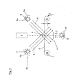
- Fig. 1 shows a printing machine in the region of the scanning 1.
- the scanning region 1 with first electromagnetic radiation 2 - preferably light - the radiation source 3 is applied.
- This radiation passes through the transparent surface 4, the radiation 2 becoming diffused.
- this diffuse radiation 2 is incident on the scanning region 1.
- This 1 is scanned by the sensor system 5.
- These two light sources together with the mirrors 6a and 7a, in whose focal points are the light sources, the lighting elements 6b and 7b. Each of these two lighting elements directs radiation 8 onto the scanning region 1.
- the second radiation 8 is direct radiation.
- the second electromagnetic radiation 8 does not fall on the translucent surface 4, which here forms the first illumination element 3 in the sense of this document.
- the printing material or the printing material web 9 are conveyed in the direction of the arrow z via the guide rollers 10, 11.
- the elements of FIG. 2 are largely identical to those of FIG. 1 , However, the first lighting element is formed by the mirror 13. This reflects diffusely, so that the first electromagnetic radiation 2 is again diffuse. This mirror 13 also transmits the first radiation 2 to the scanning region 1 as the last mechanical optically active element. As a rule (but not always), the printing ink will be located on the side of the sensor element 5 of the printing substrate 9.
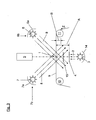
- FIG. 3 shows again the same arrangement as FIG.
- a diaphragm 15 is located between the diffuse surface 4 and the substrate 9, wherein between the diffuse surface 4 and the substrate 9, a diaphragm 15 is located.
- a diaphragm may form a shadow on the diffuse surface 4, the due to the second electromagnetic radiation 8 can be avoided.
- Such shadowing can be achieved by the interaction of the second electromagnetic radiation 8 with patterns in or on the printing material web 9.
- Such shadows can falsify the measurements of the sensor system 5.
- Another way to avoid the shadowing is to choose the distance A between the surface 4 or another optically active first element behind the printing substrate so that the second electromagnetic radiation falls past this element 4.
- this distance and the selection of the angle of incidence of the second electromagnetic radiation 8 on the printing material 9 can be matched to one another such that a second electromagnetic radiation 8 impinges on the first element 4 stored on the printing material from the point of view of the sensor system.
- This is at a minimum distance B (see FIG. 3 ), which arises from the above-mentioned geometrical considerations, the case.
- the extension of the element must also be considered
- a further possibility of avoiding the shadowing consists in a coordination of the light intensity I emitted by the first radiation source 3 and the photosensitivity of the sensor system 5.
- FIG. 4 again shows essentially the features of FIG. 2 , wherein a lens 16 is additionally present.
- This lens assumes a bundling of the first electromagnetic radiation 2, so that first electromagnetic radiation 2 of sufficient intensity arrives at the printing substrate.
- This measure can be very advantageous because the diffusion of the radiation often causes them to diverge.
- the lens other light beam means could be used.
- the mirror 13 could be pronounced as ellipsoid and / or paraboloid mirror. Incidentally, all measures relating to the provision of diffuse or parallel or to the bundling of first electromagnetic radiation 2 are made, also advantageous for second electromagnetic radiation 8 applicable and vice versa.
- the Figures 5 and 6 take up another topic, the processing of which is advantageous in connection with the present invention. It is advantageous if, in the scanning region in the web running direction z and / or in the direction of the working or printing width x, the intensity of the first and second electromagnetic radiation has the same (local) intensity profile. This is symbolized by the same curves of the graphs 20 and 21, which represent the course of the light intensity on the illuminated part of the printing material web 9 in x and / or in the z direction. Similar light sources 3, 6 and 7 can do this. Also a same or similar color temperature (in FIG. 6 spectral intensity profile) is advantageous. For clarity, in FIG. 6 the wavelength ⁇ plotted against the spectral light intensity I.
- Graphs 22 and 23 are intended to show that this pattern is the same for the first 2 and second electromagnetic radiation 8 (although the intensity here has other amounts).
Landscapes
- Engineering & Computer Science (AREA)
- Quality & Reliability (AREA)
- Investigating Materials By The Use Of Optical Means Adapted For Particular Applications (AREA)
- Length Measuring Devices By Optical Means (AREA)
- Facsimile Scanning Arrangements (AREA)
- Inking, Control Or Cleaning Of Printing Machines (AREA)
Claims (12)
- Procédé d'optimisation de l'image imprimée produite par une presse par l'adaptation des positions relatives des rouleaux d'impression, ledit procédé se basant sur un procédé de surveillance de l'image imprimée générée par la presse et comprenant les caractéristiques de procédé suivantes :- le balayage de zones imprimées de la matière imprimée (9) à l'intérieur d'une zone de balayage (1) à l'aide d'un système de capteurs (5) ;- la sollicitation de zones partielles au moins de la zone de balayage (1) avec un premier rayonnement électromagnétique (2) provenant d'un élément d'éclairage (4, 12) ;- le rayonnement électromagnétique étant homogène ;- une matière imprimée (9) transparente ou opaque étant utilisée ;- le premier rayonnement électromagnétique (2) étant amené sur la zone de balayage (1) en partant du côté de la matière imprimée (9) opposé au système de capteurs (5) ;- un deuxième rayonnement électromagnétique (8) étant amené sur la matière imprimée en partant du côté orienté vers le système de capteurs ;- le deuxième rayonnement électromagnétique (8) utilisé étant un rayonnement homogène, notamment diffus et/ou un rayonnement direct, notamment parallèle direct ;- l'angle d'incidence du deuxième rayonnement électromagnétique (8) sur la matière imprimée étant réglé de telle sorte que :- la distance (A) entre le couloir de matière imprimée et le premier élément optiquement actif (15, 13, 3), se trouvant, du point de vue du système de capteurs (5), derrière le couloir de matière imprimée (9), peut être réglé au moins sur une distance minimale (B) ;- dans lequel aucune formation d'ombre perceptible par le système de capteurs (5) ne se produit plus sur le premier élément optiquement actif (15, 13, 3) disposé en aval du couloir de matière imprimée.
- Procédé selon la revendication 1, caractérisé en ce qu'au moins une des mesures suivantes est réalisée pour mettre à disposition le rayonnement électromagnétique (2) homogène :a) la mise à disposition d'un rayonnement électromagnétique (2) diffus par le biais :- d'un miroir (12) réfléchissant diffus ;- d'une matière transparente (9) transformant le rayonnement électromagnétique (3) traversant la matière transparente en rayonnement (2) diffus ;- pour produire un rayonnement diffus de sources de rayonnement adaptées ;b) la mise à disposition d'un rayonnement électromagnétique avec des parts de rayonnement s'étendant largement parallèlement :- un miroir (6a, 7a) de forme adaptée (par exemple paraboloïde ou ellipsoïde) ;- une matière transparente de forme adaptée transformant le rayonnement électromagnétique traversant la matière transparente (9) en rayonnement avec des parts de rayonnement s'étendant largement parallèlement ;- pour produire un rayonnement parallèle de sources de rayonnement (6, 7, 13) adaptées.
- Procédé selon la revendication précédente, caractérisé en ce que les ordres de commande influencent également la durabilité du registre transversal et/ou longitudinal.
- Procédé selon la revendication précédente, caractérisé en ce que le revêtement de surface/l'entièreté de l'image imprimée sont examinés et que pour ce faire, au moins un des composants suivants de l'image imprimée est balayé :- parties sélectionnées du motif imprimé ;- repères d'impression imprimés sur la matière imprimée à l'extérieur du motif imprimé ;- largeur totale du motif imprimé.
- Procédé selon l'une quelconque des revendications précédentes, caractérisé en ce que le système de capteurs (5) mesure l'intensité du rayonnement incident sur le système de capteurs (5) en provenance de la zone de balayage (1).
- Presse rotative, dans laquelle les positions relatives des rouleaux d'impression peuvent être optimisées sur la base de la surveillance de l'image imprimée ; et
contenant un système de surveillance de l'image imprimée avec les caractéristiques suivantes :- au moins un système de capteurs (5) servant au balayage de zones imprimées de la matière imprimée (9) à l'intérieur d'une zone de balayage (1) ;- au moins un élément d'éclairage (4, 12) servant à la sollicitation de zones partielles au moins de la zone de balayage (1) avec un premier rayonnement électromagnétique (2) ;- au moins un élément d'éclairage (4) étant placé sur le côté de la matière imprimée (9) opposé au système de capteurs (5) pour réaliser la sollicitation de zones partielles au moins de la zone de balayage (1) avec un premier rayonnement électromagnétique (2) homogène ;- au moins un deuxième élément d'éclairage (4) étant disposé sur le côté de la matière imprimée (9) orienté vers le système de capteurs (5) pour réaliser la sollicitation de zones partielles au moins de la zone de balayage (1) avec un deuxième rayonnement électromagnétique (2) ;- à l'aide duquel au moins un deuxième élément d'éclairage peut produire un rayonnement (8) homogène, notamment un rayonnement diffus et/ou un rayonnement parallèle, notamment parallèle direct ;- l'angle d'incidence du deuxième rayonnement électromagnétique (8) étant réglé de telle sorte sur la matière imprimée que :- la distance (A) entre le couloir de matière imprimée et le premier élément optiquement actif (15, 13, 3), se trouvant, du point de vue du système de capteurs (5) derrière le couloir de matière imprimée (9), mesure au moins une distance minimale (B) ;- dans lequel aucune formation d'ombre perceptible par le système de capteurs (5) ne se produit plus sur le premier élément optiquement actif (15, 13, 3) disposé en aval du couloir de matière imprimée. - Presse rotative selon la revendication précédente, caractérisée en ce qu'un deuxième élément d'éclairage (6b, 7b) est disposé sur le côté de la matière imprimée orienté vers le système de capteurs (5) au moins pour réaliser la sollicitation de zones partielles au moins de la zone de balayage (1) avec un deuxième rayonnement électromagnétique (8).
- Presse rotative selon l'une quelconque des revendications précédentes, caractérisée en ce qu'au moins deux deuxièmes éléments d'éclairage (6b, 7b) sont prévus.
- Presse rotative selon l'une quelconque des revendications précédentes, caractérisée en ce que l'au moins un système de capteurs (5) comprend au moins une caméra à lignes.
- Presse rotative selon l'une quelconque des revendications précédentes, caractérisée en ce que l'au moins un système de capteurs comporte une zone de balayage (1) recouvrant :- les zones partielles de la largeur d'impression possible de la presse rotative ; ou- la largeur d'impression totale possible de la presse rotative.
- Système de surveillance de l'image imprimée produite par une presse avec lequel on détermine des valeurs de mesure sur la base desquelles les positions relatives des rouleaux d'impression peuvent être optimisées ;
contenant les caractéristiques suivantes :- au moins un système de capteurs (5) servant au balayage de zones imprimées de la matière imprimée (9) à l'intérieur d'une zone de balayage (1) ;- au moins un élément d'éclairage (4, 12) servant à la sollicitation de zones partielles au moins de la zone de balayage (1) avec un premier rayonnement électromagnétique (2) ;- l'au moins un élément d'éclairage (4, 12) étant disposé sur le côté de la matière imprimée (9) opposé au système de capteurs (5) pour réaliser la sollicitation de zones partielles au moins de la zone de balayage (1) avec un premier rayonnement électromagnétique (2) ;- et au moins un deuxième élément d'éclairage (4) étant disposé sur le côté de la matière imprimée (9) orienté vers le système de capteurs (5) pour réaliser la sollicitation de zones partielles au moins de la zone de balayage (1) avec un deuxième rayonnement électromagnétique (2) ;- un rayonnement (8) homogène, notamment un rayonnement diffus et/ou un rayonnement parallèle, notamment parallèle direct, pouvant être produit avec l'au moins un deuxième élément d'éclairage ;- l'angle d'incidence du deuxième rayonnement électromagnétique (8) sur la matière imprimée étant réglé de telle sorte que :- la distance (A) entre le couloir de matière imprimée et le premier élément optiquement actif (15, 13, 3), se trouvant, du point de vue du système de capteurs (5) derrière le couloir de matière imprimée (9) mesure au moins une distance minimale (B) ;- dans lequel aucune formation d'ombre perceptible par le système de capteurs (5) ne se produit plus sur le premier élément optiquement actif (15, 13, 3) disposé en aval du couloir de matière imprimée. - Système selon la revendication précédente, caractérisé en ce que le système comporte des moyens de communication à l'aide desquels le système peut être relié à la commande de machine de la presse.
Applications Claiming Priority (2)
| Application Number | Priority Date | Filing Date | Title |
|---|---|---|---|
| DE200710025910 DE102007025910B4 (de) | 2007-06-01 | 2007-06-01 | Hintergrundbeleuchtung |
| PCT/EP2008/004229 WO2008145349A2 (fr) | 2007-06-01 | 2008-05-28 | Procédé, système et presse rotative permettant la surveillance de l'image d'impression |
Publications (2)
| Publication Number | Publication Date |
|---|---|
| EP2155492A2 EP2155492A2 (fr) | 2010-02-24 |
| EP2155492B1 true EP2155492B1 (fr) | 2015-04-29 |
Family
ID=39917461
Family Applications (1)
| Application Number | Title | Priority Date | Filing Date |
|---|---|---|---|
| EP20080784501 Not-in-force EP2155492B1 (fr) | 2007-06-01 | 2008-05-28 | Procédé, presse rotative et système, dans lesquels les images générées par la presse rotative sont optimisées par l'adaptation de la position relative des rouleaux d'impression |
Country Status (4)
| Country | Link |
|---|---|
| EP (1) | EP2155492B1 (fr) |
| DE (1) | DE102007025910B4 (fr) |
| ES (1) | ES2542698T3 (fr) |
| WO (1) | WO2008145349A2 (fr) |
Families Citing this family (6)
| Publication number | Priority date | Publication date | Assignee | Title |
|---|---|---|---|---|
| US8823953B2 (en) | 2008-05-21 | 2014-09-02 | Ferag Ag | Optical position detection |
| WO2013026791A1 (fr) * | 2011-08-22 | 2013-02-28 | Windmöller & Hölscher Kg | Machine et procédé d'impression de bandes d'impression |
| WO2013026792A1 (fr) * | 2011-08-22 | 2013-02-28 | Windmöller & Hölscher Kg | Machine et procédé d'impression de bandes de matériau |
| DE102015109412A1 (de) * | 2015-06-12 | 2016-12-15 | Manroland Web Systems Gmbh | Registerhaltiges Bedrucken transparenter Substrate |
| DE102015114575B4 (de) * | 2015-09-01 | 2017-05-24 | Stephan Krebs | Vorrichtung zur Druckbildkontrolle |
| DE102016100437B4 (de) * | 2016-01-12 | 2018-08-02 | Stephan Krebs | Vorrichtung zur Druckbildkontrolle |
Family Cites Families (13)
| Publication number | Priority date | Publication date | Assignee | Title |
|---|---|---|---|---|
| NL7711138A (nl) * | 1976-11-01 | 1978-05-03 | Ici Ltd | Detectie van discontinuiteiten in bewegende banen van plastic materiaal. |
| US5461417A (en) * | 1993-02-16 | 1995-10-24 | Northeast Robotics, Inc. | Continuous diffuse illumination method and apparatus |
| AU678875B2 (en) * | 1993-12-16 | 1997-06-12 | Commonwealth Scientific And Industrial Research Organisation | Instrument for on-line detection of coloured contaminants in white fibre mass |
| AUPM300993A0 (en) * | 1993-12-16 | 1994-01-20 | Commonwealth Scientific And Industrial Research Organisation | Instrument |
| JP3808937B2 (ja) * | 1996-05-14 | 2006-08-16 | 大日本印刷株式会社 | 印刷物検査装置用照明装置 |
| DE19703129B4 (de) * | 1997-01-29 | 2014-08-21 | Heidelberger Druckmaschinen Ag | Verfahren zur Bewertung der Qualität eines im Mehrfarbendruck auf einem Bedruckstoff erzeugten Druckbildes |
| CH692847A5 (fr) * | 1998-09-02 | 2002-11-29 | Bobst Sa | Dispositif automatique détectant les défauts d'impression apparaissant sur des bandes métallisées ou sur tout autre support d'impression comprenant une prédominance de surfaces de couleurs s |
| DE20122584U1 (de) * | 2001-03-27 | 2006-07-27 | Windmöller & Hölscher Kg | Einheit zur Einstellung des Druckbildes in einer Rotationsdruckmaschine |
| US7105848B2 (en) * | 2002-04-15 | 2006-09-12 | Wintriss Engineering Corporation | Dual level out-of-focus light source for amplification of defects on a surface |
| DE10352274B4 (de) * | 2002-11-11 | 2009-02-26 | Leuze Electronic Gmbh & Co Kg | Verfahren zur Erfassung von Objektstrukturen mittels eines optischen Sensors |
| DE10261221A1 (de) * | 2002-12-20 | 2004-07-15 | Océ Document Technologies GmbH | Verfahren und Vorrichtung zur Echtzeitkontrolle von Druckbildern |
| US7017492B2 (en) * | 2003-03-10 | 2006-03-28 | Quad/Tech, Inc. | Coordinating the functioning of a color control system and a defect detection system for a printing press |
| DE102004044341B4 (de) * | 2003-10-13 | 2017-09-07 | Heidelberger Druckmaschinen Ag | Bogendruckmaschine mit optischer Sensoranordnung für einen Bedruckstoff |
-
2007
- 2007-06-01 DE DE200710025910 patent/DE102007025910B4/de not_active Expired - Fee Related
-
2008
- 2008-05-28 ES ES08784501.2T patent/ES2542698T3/es active Active
- 2008-05-28 WO PCT/EP2008/004229 patent/WO2008145349A2/fr not_active Ceased
- 2008-05-28 EP EP20080784501 patent/EP2155492B1/fr not_active Not-in-force
Also Published As
| Publication number | Publication date |
|---|---|
| WO2008145349A2 (fr) | 2008-12-04 |
| EP2155492A2 (fr) | 2010-02-24 |
| ES2542698T3 (es) | 2015-08-10 |
| WO2008145349A3 (fr) | 2009-01-29 |
| DE102007025910A1 (de) | 2008-12-04 |
| DE102007025910B4 (de) | 2013-08-29 |
Similar Documents
| Publication | Publication Date | Title |
|---|---|---|
| EP2566695B1 (fr) | Procede de reglage et dispositif pour determiner la distance optimale entre au moins deux cylindres impliques dans le procede d'impression | |
| EP0884178B1 (fr) | Procédé pour reguler l'encrage dans une machine d'impression | |
| EP1902308B1 (fr) | Appareil pour inspecter une surface | |
| EP2155492B1 (fr) | Procédé, presse rotative et système, dans lesquels les images générées par la presse rotative sont optimisées par l'adaptation de la position relative des rouleaux d'impression | |
| EP1744884A1 (fr) | Procede pour determiner des valeurs de densite et/ou d'encrage et dispositif d'impression pour la mise en oeuvre dudit procede | |
| DE2150319A1 (de) | Verfahren und Vorrichtung zum Bestimmen der Farbdichte von Farbreproduktionen | |
| DE69421643T2 (de) | Optische Prüfvorrichtung für die Füllung von Zigaretten | |
| EP3258244A2 (fr) | Dispositif d'inspection et procédé d'inspection de l'image de surface d'un objet plat présentant un échantillon | |
| EP1607220A2 (fr) | Machine d'impression avec un système d'inspection en ligne | |
| EP0505769B1 (fr) | Procédé de détermination du recouvrement de la surface d'un modèle, particulièrement une plaque, et dispositif pour exécuter ce procédé | |
| EP2523809B1 (fr) | Procédé et dispositif destinés à optimiser la position relative d'au moins deux cylindres d'impression | |
| DE3113674A1 (de) | Vorrichtung zum messen der feuchtmittelmenge auf der druckplatte einer offset-druckmaschine | |
| EP2283307B1 (fr) | Détection optique de position | |
| DE102004059951A1 (de) | Vorrichtung zur Untersuchung von Dokumenten | |
| DE10142636B4 (de) | Verfahren und Vorrichtung zur Detektion einer Position einer bewegten Bedruckstoffbahn | |
| DE10139717A1 (de) | Verfahren und Vorrichtung zur Untersuchung von Defekten in oder auf Blattgut | |
| DE102007006333A1 (de) | Verfahren und Vorrichtung zur Erfassung der Lage und/oder der Form zumindest eines Abschnitts von bewegtem, flachem Bedruckstoff | |
| DE10339651B3 (de) | Verfahren und Vorrichtung zur Ermittlung von Rastertonwerten durch direkte Aufnahme von verschiedenen drucktechnischen Substraten | |
| DE102010009957A1 (de) | Vorrichtung zur Abbildung eines flächigen Objekts | |
| DE102018100499A1 (de) | Vorrichtung und Verfahren der Tabak verarbeitenden Industrie mit einer Beleuchtungsvorrichtung zum optischen Prüfen von stabförmigen Artikeln | |
| DE2917519B1 (de) | Vorrichtung an Druckmaschinen zur Bestimmung des Trockengrades der Bedruckstoffe | |
| EP3718728A1 (fr) | Système de surveillance de bande et procédé de surveillance de bande | |
| DE10117048C1 (de) | Verfahren und Vorrichtung zur Detektion von Oberflächendefekten auf Messobjekten | |
| DE102004022955A1 (de) | Vorrichtung und Verfahren zum Erfassen der Lage einer Kante eines Produkts | |
| AT376505B (de) | Verfahren zur pruefung des verschmutzungsgrades von banknoten |
Legal Events
| Date | Code | Title | Description |
|---|---|---|---|
| PUAI | Public reference made under article 153(3) epc to a published international application that has entered the european phase |
Free format text: ORIGINAL CODE: 0009012 |
|
| 17P | Request for examination filed |
Effective date: 20100104 |
|
| AK | Designated contracting states |
Kind code of ref document: A2 Designated state(s): AT BE BG CH CY CZ DE DK EE ES FI FR GB GR HR HU IE IS IT LI LT LU LV MC MT NL NO PL PT RO SE SI SK TR |
|
| RIN1 | Information on inventor provided before grant (corrected) |
Inventor name: FREI, BERNHARD Inventor name: WIEBE, MICHAEL Inventor name: DELERE, HOLGER Inventor name: LODDENKOETTER, MANFRED Inventor name: KRUEMPELMANN, MARTIN |
|
| DAX | Request for extension of the european patent (deleted) | ||
| GRAP | Despatch of communication of intention to grant a patent |
Free format text: ORIGINAL CODE: EPIDOSNIGR1 |
|
| INTG | Intention to grant announced |
Effective date: 20141113 |
|
| GRAS | Grant fee paid |
Free format text: ORIGINAL CODE: EPIDOSNIGR3 |
|
| GRAA | (expected) grant |
Free format text: ORIGINAL CODE: 0009210 |
|
| AK | Designated contracting states |
Kind code of ref document: B1 Designated state(s): AT BE BG CH CY CZ DE DK EE ES FI FR GB GR HR HU IE IS IT LI LT LU LV MC MT NL NO PL PT RO SE SI SK TR |
|
| REG | Reference to a national code |
Ref country code: GB Ref legal event code: FG4D Free format text: NOT ENGLISH |
|
| REG | Reference to a national code |
Ref country code: CH Ref legal event code: EP |
|
| REG | Reference to a national code |
Ref country code: AT Ref legal event code: REF Ref document number: 724204 Country of ref document: AT Kind code of ref document: T Effective date: 20150515 |
|
| REG | Reference to a national code |
Ref country code: IE Ref legal event code: FG4D Free format text: LANGUAGE OF EP DOCUMENT: GERMAN |
|
| REG | Reference to a national code |
Ref country code: DE Ref legal event code: R096 Ref document number: 502008012944 Country of ref document: DE Effective date: 20150603 |
|
| REG | Reference to a national code |
Ref country code: CH Ref legal event code: NV Representative=s name: FIAMMENGHI-FIAMMENGHI, CH |
|
| REG | Reference to a national code |
Ref country code: ES Ref legal event code: FG2A Ref document number: 2542698 Country of ref document: ES Kind code of ref document: T3 Effective date: 20150810 |
|
| REG | Reference to a national code |
Ref country code: NL Ref legal event code: VDEP Effective date: 20150429 |
|
| REG | Reference to a national code |
Ref country code: LT Ref legal event code: MG4D |
|
| PG25 | Lapsed in a contracting state [announced via postgrant information from national office to epo] |
Ref country code: NL Free format text: LAPSE BECAUSE OF FAILURE TO SUBMIT A TRANSLATION OF THE DESCRIPTION OR TO PAY THE FEE WITHIN THE PRESCRIBED TIME-LIMIT Effective date: 20150429 |
|
| PG25 | Lapsed in a contracting state [announced via postgrant information from national office to epo] |
Ref country code: FI Free format text: LAPSE BECAUSE OF FAILURE TO SUBMIT A TRANSLATION OF THE DESCRIPTION OR TO PAY THE FEE WITHIN THE PRESCRIBED TIME-LIMIT Effective date: 20150429 Ref country code: NO Free format text: LAPSE BECAUSE OF FAILURE TO SUBMIT A TRANSLATION OF THE DESCRIPTION OR TO PAY THE FEE WITHIN THE PRESCRIBED TIME-LIMIT Effective date: 20150729 Ref country code: HR Free format text: LAPSE BECAUSE OF FAILURE TO SUBMIT A TRANSLATION OF THE DESCRIPTION OR TO PAY THE FEE WITHIN THE PRESCRIBED TIME-LIMIT Effective date: 20150429 Ref country code: LT Free format text: LAPSE BECAUSE OF FAILURE TO SUBMIT A TRANSLATION OF THE DESCRIPTION OR TO PAY THE FEE WITHIN THE PRESCRIBED TIME-LIMIT Effective date: 20150429 Ref country code: PT Free format text: LAPSE BECAUSE OF FAILURE TO SUBMIT A TRANSLATION OF THE DESCRIPTION OR TO PAY THE FEE WITHIN THE PRESCRIBED TIME-LIMIT Effective date: 20150831 |
|
| PG25 | Lapsed in a contracting state [announced via postgrant information from national office to epo] |
Ref country code: IS Free format text: LAPSE BECAUSE OF FAILURE TO SUBMIT A TRANSLATION OF THE DESCRIPTION OR TO PAY THE FEE WITHIN THE PRESCRIBED TIME-LIMIT Effective date: 20150829 Ref country code: LV Free format text: LAPSE BECAUSE OF FAILURE TO SUBMIT A TRANSLATION OF THE DESCRIPTION OR TO PAY THE FEE WITHIN THE PRESCRIBED TIME-LIMIT Effective date: 20150429 Ref country code: GR Free format text: LAPSE BECAUSE OF FAILURE TO SUBMIT A TRANSLATION OF THE DESCRIPTION OR TO PAY THE FEE WITHIN THE PRESCRIBED TIME-LIMIT Effective date: 20150730 |
|
| PG25 | Lapsed in a contracting state [announced via postgrant information from national office to epo] |
Ref country code: EE Free format text: LAPSE BECAUSE OF FAILURE TO SUBMIT A TRANSLATION OF THE DESCRIPTION OR TO PAY THE FEE WITHIN THE PRESCRIBED TIME-LIMIT Effective date: 20150429 Ref country code: DK Free format text: LAPSE BECAUSE OF FAILURE TO SUBMIT A TRANSLATION OF THE DESCRIPTION OR TO PAY THE FEE WITHIN THE PRESCRIBED TIME-LIMIT Effective date: 20150429 Ref country code: MC Free format text: LAPSE BECAUSE OF FAILURE TO SUBMIT A TRANSLATION OF THE DESCRIPTION OR TO PAY THE FEE WITHIN THE PRESCRIBED TIME-LIMIT Effective date: 20150429 |
|
| REG | Reference to a national code |
Ref country code: DE Ref legal event code: R097 Ref document number: 502008012944 Country of ref document: DE |
|
| REG | Reference to a national code |
Ref country code: IE Ref legal event code: MM4A |
|
| PG25 | Lapsed in a contracting state [announced via postgrant information from national office to epo] |
Ref country code: PL Free format text: LAPSE BECAUSE OF FAILURE TO SUBMIT A TRANSLATION OF THE DESCRIPTION OR TO PAY THE FEE WITHIN THE PRESCRIBED TIME-LIMIT Effective date: 20150429 Ref country code: SK Free format text: LAPSE BECAUSE OF FAILURE TO SUBMIT A TRANSLATION OF THE DESCRIPTION OR TO PAY THE FEE WITHIN THE PRESCRIBED TIME-LIMIT Effective date: 20150429 Ref country code: RO Free format text: LAPSE BECAUSE OF NON-PAYMENT OF DUE FEES Effective date: 20150429 |
|
| PLBE | No opposition filed within time limit |
Free format text: ORIGINAL CODE: 0009261 |
|
| STAA | Information on the status of an ep patent application or granted ep patent |
Free format text: STATUS: NO OPPOSITION FILED WITHIN TIME LIMIT |
|
| GBPC | Gb: european patent ceased through non-payment of renewal fee |
Effective date: 20150729 |
|
| 26N | No opposition filed |
Effective date: 20160201 |
|
| REG | Reference to a national code |
Ref country code: FR Ref legal event code: ST Effective date: 20160311 |
|
| PG25 | Lapsed in a contracting state [announced via postgrant information from national office to epo] |
Ref country code: IE Free format text: LAPSE BECAUSE OF NON-PAYMENT OF DUE FEES Effective date: 20150528 Ref country code: GB Free format text: LAPSE BECAUSE OF NON-PAYMENT OF DUE FEES Effective date: 20150729 |
|
| PG25 | Lapsed in a contracting state [announced via postgrant information from national office to epo] |
Ref country code: SI Free format text: LAPSE BECAUSE OF FAILURE TO SUBMIT A TRANSLATION OF THE DESCRIPTION OR TO PAY THE FEE WITHIN THE PRESCRIBED TIME-LIMIT Effective date: 20150429 Ref country code: FR Free format text: LAPSE BECAUSE OF NON-PAYMENT OF DUE FEES Effective date: 20150629 |
|
| REG | Reference to a national code |
Ref country code: AT Ref legal event code: MM01 Ref document number: 724204 Country of ref document: AT Kind code of ref document: T Effective date: 20150528 |
|
| PG25 | Lapsed in a contracting state [announced via postgrant information from national office to epo] |
Ref country code: AT Free format text: LAPSE BECAUSE OF NON-PAYMENT OF DUE FEES Effective date: 20150528 |
|
| PG25 | Lapsed in a contracting state [announced via postgrant information from national office to epo] |
Ref country code: MT Free format text: LAPSE BECAUSE OF FAILURE TO SUBMIT A TRANSLATION OF THE DESCRIPTION OR TO PAY THE FEE WITHIN THE PRESCRIBED TIME-LIMIT Effective date: 20150429 |
|
| PG25 | Lapsed in a contracting state [announced via postgrant information from national office to epo] |
Ref country code: BG Free format text: LAPSE BECAUSE OF FAILURE TO SUBMIT A TRANSLATION OF THE DESCRIPTION OR TO PAY THE FEE WITHIN THE PRESCRIBED TIME-LIMIT Effective date: 20150429 Ref country code: HU Free format text: LAPSE BECAUSE OF FAILURE TO SUBMIT A TRANSLATION OF THE DESCRIPTION OR TO PAY THE FEE WITHIN THE PRESCRIBED TIME-LIMIT; INVALID AB INITIO Effective date: 20080528 |
|
| PG25 | Lapsed in a contracting state [announced via postgrant information from national office to epo] |
Ref country code: CY Free format text: LAPSE BECAUSE OF FAILURE TO SUBMIT A TRANSLATION OF THE DESCRIPTION OR TO PAY THE FEE WITHIN THE PRESCRIBED TIME-LIMIT Effective date: 20150429 Ref country code: SE Free format text: LAPSE BECAUSE OF FAILURE TO SUBMIT A TRANSLATION OF THE DESCRIPTION OR TO PAY THE FEE WITHIN THE PRESCRIBED TIME-LIMIT Effective date: 20150429 |
|
| PG25 | Lapsed in a contracting state [announced via postgrant information from national office to epo] |
Ref country code: BE Free format text: LAPSE BECAUSE OF NON-PAYMENT OF DUE FEES Effective date: 20150531 |
|
| PG25 | Lapsed in a contracting state [announced via postgrant information from national office to epo] |
Ref country code: TR Free format text: LAPSE BECAUSE OF FAILURE TO SUBMIT A TRANSLATION OF THE DESCRIPTION OR TO PAY THE FEE WITHIN THE PRESCRIBED TIME-LIMIT Effective date: 20150429 |
|
| PG25 | Lapsed in a contracting state [announced via postgrant information from national office to epo] |
Ref country code: LU Free format text: LAPSE BECAUSE OF NON-PAYMENT OF DUE FEES Effective date: 20150528 |
|
| PGFP | Annual fee paid to national office [announced via postgrant information from national office to epo] |
Ref country code: DE Payment date: 20180531 Year of fee payment: 11 Ref country code: CH Payment date: 20180525 Year of fee payment: 11 Ref country code: CZ Payment date: 20180525 Year of fee payment: 11 Ref country code: ES Payment date: 20180618 Year of fee payment: 11 |
|
| PGFP | Annual fee paid to national office [announced via postgrant information from national office to epo] |
Ref country code: IT Payment date: 20180524 Year of fee payment: 11 |
|
| REG | Reference to a national code |
Ref country code: DE Ref legal event code: R119 Ref document number: 502008012944 Country of ref document: DE |
|
| REG | Reference to a national code |
Ref country code: CH Ref legal event code: PL |
|
| PG25 | Lapsed in a contracting state [announced via postgrant information from national office to epo] |
Ref country code: CZ Free format text: LAPSE BECAUSE OF NON-PAYMENT OF DUE FEES Effective date: 20190528 Ref country code: CH Free format text: LAPSE BECAUSE OF NON-PAYMENT OF DUE FEES Effective date: 20190531 Ref country code: LI Free format text: LAPSE BECAUSE OF NON-PAYMENT OF DUE FEES Effective date: 20190531 |
|
| PG25 | Lapsed in a contracting state [announced via postgrant information from national office to epo] |
Ref country code: DE Free format text: LAPSE BECAUSE OF NON-PAYMENT OF DUE FEES Effective date: 20191203 Ref country code: IT Free format text: LAPSE BECAUSE OF NON-PAYMENT OF DUE FEES Effective date: 20190528 |
|
| REG | Reference to a national code |
Ref country code: ES Ref legal event code: FD2A Effective date: 20201001 |
|
| PG25 | Lapsed in a contracting state [announced via postgrant information from national office to epo] |
Ref country code: ES Free format text: LAPSE BECAUSE OF NON-PAYMENT OF DUE FEES Effective date: 20190529 |