EP2155507B1 - Abschleppfahrzeugführung für eine anhängerkupplung - Google Patents
Abschleppfahrzeugführung für eine anhängerkupplung Download PDFInfo
- Publication number
- EP2155507B1 EP2155507B1 EP08724631.0A EP08724631A EP2155507B1 EP 2155507 B1 EP2155507 B1 EP 2155507B1 EP 08724631 A EP08724631 A EP 08724631A EP 2155507 B1 EP2155507 B1 EP 2155507B1
- Authority
- EP
- European Patent Office
- Prior art keywords
- towing vehicle
- trailer
- hitch
- target
- vehicle
- Prior art date
- Legal status (The legal status is an assumption and is not a legal conclusion. Google has not performed a legal analysis and makes no representation as to the accuracy of the status listed.)
- Not-in-force
Links
Images





Classifications
-
- B—PERFORMING OPERATIONS; TRANSPORTING
- B60—VEHICLES IN GENERAL
- B60D—VEHICLE CONNECTIONS
- B60D1/00—Traction couplings; Hitches; Draw-gear; Towing devices
- B60D1/24—Traction couplings; Hitches; Draw-gear; Towing devices characterised by arrangements for particular functions
- B60D1/36—Traction couplings; Hitches; Draw-gear; Towing devices characterised by arrangements for particular functions for facilitating connection, e.g. hitch catchers
Definitions
- the present disclosure relates to hitching a towing vehicle to a trailer or other vehicle to be towed and relates particularly to a guidance system and a method for its use in guiding a towing vehicle accurately to a position in which a trailer hitch can be coupled between the trailer and the towing vehicle.
- trailers such as horse trailers and camping trailers are towed behind vehicles such as pickup trucks or sport utility vehicles. While small utility trailers can often be hitched to such a towing vehicle by lifting the tongue of the trailer manually or by moving the tongue of the trailer while its weight is supported on a stand including a wheel or skid, many trailers are large enough so that hitching them to a towing vehicle requires that the towing vehicle be backed accurately to a position in which a trailer hitch ball mounted on the towing vehicle is immediately beneath the coupler carried on the trailer or other vehicle that is to be towed.
- the trailer hitch ball or other hitch mating device is not in view of the operator of the vehicle. Even in a pickup truck with its tailgate lowered, the trailer hitch ball is normally hidden from the field of view of the pickup truck operator.
- the towing vehicle is, for example, a larger truck or a sports utility vehicle loaded with equipment to be used during a long trip, for example, the rearward visibility may be even more limited, so that backing the towing vehicle requires use of side-mounted mirrors. Backing a towing vehicle accurately into position thus usually requires a driver operator to rely upon hand signals and voice commands from a second person in position to observe the approach of the towing vehicle toward the trailer. Even for an experienced team of a driver and a signaling person such an operation is difficult, since the final position of the towing vehicle must be accurate within a fraction of an inch.
- Document US 2005/0285371 A1 shows an apparatus for guiding an operator of a forming vehicle according the preamble of claim 1 and a method for moving a towing vehicle according the preamble of claim 12.
- a team of a driver and a signaling person with little experience or who only rarely hitch a towing vehicle to a trailer can experience great difficulty, often requiring many approach attempts before the towing vehicle can be placed in the correct position.
- the operation is not quickly successful, it can cause considerable disagreement, blame-laying, and unhappiness, thereby creating interpersonal stress between people who are attempting to achieve relaxation and enjoyment of travel with a recreational vehicle.
- apparatus could also be used to provide the operator of the towing vehicle with a clear view of an area behind the towing vehicle during the operation of moving the towing vehicle into position for coupling a trailer hitch, and also to provide a view of areas behind the towed vehicle.
- a camera mounted on the towing vehicle provides an image that can be viewed by the operator of the towing vehicle, showing the front of the trailer and a light beam projected from the towing vehicle toward a target mounted near a part of the hitch on the trailer or other vehicle to be towed.
- a target to be attached to a hitch component on a trailer that is to be towed a target to be attached to a hitch component on a trailer that is to be towed
- a light beam projector to be attached to a hitch component on the towing vehicle
- a camera to be carried on the towing vehicle in a location where the camera can form and transmit an image to a display that can be viewed by an operator of the towing vehicle as the towing vehicle is backed toward the required hitch-mating position for connecting the towing vehicle to the trailer.
- a laser or other light beam projector is located on the towing vehicle so that it projects a light beam onto the target so as indicate visibly the relative positions of the bitch portions that must be connected.
- a target for a light beam is provided on the trailer
- a light beam projector is provided on the towing vehicle
- the towing vehicle is backed toward the required mating position of the hitch components while the operator observes an image of the target and the hitch component on the trailer, provided by a camera located on the towing vehicle, and steers the towing vehicle so that the light beam is projected onto the target and can be observed in the camera image as an indication of the position of the towing vehicle relative to the trailer.
- a trailer hitch for a towing vehicle (not shown) includes a short drawbar 16 on which is mounted a trailer hitch ball 18 as is commonly used in interconnecting towing vehicles with trailers ranging from the smallest in size up to those weighing several thousand pounds.
- a trailer such as a recreational camping trailer includes a hitch coupler 20 on a its tongue 22. Except for the smallest of trailers, a lift device such as an adjustable jack stand 24 is associated with the tongue, either as a permanent attachment or temporarily mounted on the tongue 22 whenever the trailer is not connected to a towing vehicle.
- the lift device is used as shown schematically in FIG. 2 to raise the tongue of the trailer to a great enough height to permit the trailer hitch ball 18 or equivalent portion of the trailer hitch 16 on the towing vehicle to be placed beneath the trailer hitch coupler 20 that is mounted on the tongue 22 of the trailer, as shown in FIG. 2 .
- the lift device 24 may be operated to lower the tongue of the trailer until the coupler 20 moves down to surround and rest upon the hitch ball 18, allowing the coupler to be fastened to mate the coupler securely with the trailer hitch ball.
- the lift device 24 can be operated to place the weight of the trailer tongue on the trailer hitch of the towing vehicle.
- a towing vehicle for example a pickup truck 26, is shown in an initial position ahead of a trailer 28, ready to be backed toward the trailer 28 to permit the hitch coupler 20 on the trailer tongue 22 to be mated with the trailer hitch ball 18 carried on the towing vehicle 26.
- a hitch-alignment guidance system as disclosed herein includes in one embodiment a towing vehicle guidance module 30 mounted on the trailer hitch ball 18, a corresponding towed vehicle module 32 that is mounted on the tongue 22 of the trailer 28, and a video display device 34 (as shown in FIG. 9 ) located in view of the operator of the towing vehicle 26.
- the towing vehicle module 30 is mounted adjustably on the hitch ball 18 of the towing vehicle 26 and thus can be rotated about any axis to place it into the correct alignment with respect to the towing vehicle 26.
- the corresponding towed vehicle module 32 may be equipped with a mounting ball 36 similar in size to the trailer hitch ball 18, and may be attached to the tongue 22 of the trailer by mating the mounting ball 36 with the trailer hitch coupler 20 on the trailer tongue 22.
- the mounting ball 36 may be made of a suitable metal or plastics material, with a plastics resin being preferred because of its lower cost and weight.
- the towed vehicle module 32 is also adjustable about any axis to align it for use of the apparatus disclosed herein to guide the towing vehicle 26 into position to mate the coupler 20 with the hitch ball 18.
- the towing vehicle module 30 may have a housing or case that can be folded about a hinge 42 into a compact configuration comparable in size to a telephone handset.
- the towing vehicle module may also be separable into two separate portions, by removal of an upper portion 44 from a generally horizontal base portion 46 so that the upper portion 44 can be used separately, as will be explained presently.
- a quick disconnect multi-conductor junction 48 is provided to permit the upper portion 44 of the towing vehicle module 30 to be folded about the hinge 42 as suggested by the arrow 50 to place the towing vehicle module 30 into its more compact configuration, or to permit the upper portion 44 to be removed from the base portion 46 for separate use.
- the towing vehicle module 30 is shown mounted on the trailer hitch ball 18, to which it may be attached removably by a suitably strong magnet 52 housed in the base portion 46, and an arrangement of feet 54 that rest on the hitch ball 18, acting as a socket to support the towing vehicle module 30 so that it can be swiveled in any direction about the hitch ball 18.
- a suitably strong magnet 52 housed in the base portion 46
- feet 54 that rest on the hitch ball 18, acting as a socket to support the towing vehicle module 30 so that it can be swiveled in any direction about the hitch ball 18.
- the towing vehicle module 30 could be attached by using a different arrangement not shown herein but which should permit adjustment in all directions.
- the base portion 46 of the towing vehicle module 30 includes a hitch alignment indicating light beam projector 56 such as a small laser of the type used in laser pointers, arranged to project a beam 57 of visible light directly upward, that is, in a direction perpendicular to a flat upper surface 58 of the base portion.
- the projector 56 is located so that when the upper surface 58 of the base portion 46 is horizontal the beam of light from the projector 56 will be directed vertically upwards above the center of the hitch ball 18.
- the light beam projector may be arranged to project a cruciform beam 57 upward, or it may project a simple, narrow beam to shine a small spot on a surface.
- the base portion 46 of the towing vehicle module 30 preferably includes a level 60 to aid in placing the towing vehicle module 30 on the hitch ball 18 so that the upper surface 58 of the base portion 46 is horizontal when the towing vehicle module 30 is mounted and ready for use.
- Leveling may be accomplished using a single circular level 60 as shown or a pair of small elongate tubular levels oriented perpendicular to each other and aligned with the upper surface 58 of the base portion 46.
- the top of the base portion 46 may include a removable transparent plate 62 of strong plastic, and a pair of small lamps 64, such as upwardly directed LEDs, may be housed within the base portion 46 to provide illumination during nighttime use of the hitching guidance system.
- a small long distance guidance light beam projector 66 which may also be a small laser, is mounted at the rear end of the base portion 46 and is arranged to project a beam 68 of light rearwardly from the towing vehicle to serve as a long distance guide and a distance indicator when the towing vehicle module 30 is correctly mounted and adjusted.
- the position of the light beam projector 66 may be adjustable with respect to the base portion 46 in order to project the beam of light at a selected acute angle 70 above horizontal.
- the angle 70 may be selected so as to make the beam of light 68 strike the front of the trailer 28 or other vehicle to be towed in a visible position when the towing vehicle 26 is separated from the trailer 28 by a selected distance.
- the light beam projector 66 may be a low power laser oriented at an angle 70 of 22.5 degrees above horizontal, so that the beam 68 of light will strike the front of a camper trailer, depending on its height, when the towing vehicle 26 is several feet ahead of the hitch mating position in which the trailer 28 can be coupled to the towing vehicle 26.
- the upper portion 44 of the towing vehicle module 30 includes an electronic image-forming device such as a video camera 72 arranged to provide an electrical image signal that can be transmitted either wirelessly or by wire, for continuous display on a monitor screen 74 of the video display device 34 located in the operator's cab of the vehicle where it can be seen conveniently by the vehicle operator.
- the video camera 72 may be a small digital video camera including a sensing device capable of providing digital video image transmission of suitable definition for display on the monitor screen 74.
- a target reticle 76 may be included in the camera so as to be visible in the image transmitted by the camera to the monitor screen 74, as shown in FIG. 8 , as an indication of the center of the field of view of the camera.
- the camera 72 includes a self-leveling lens and automatically focusing arrangement in one embodiment.
- a connector 78 is provided for a cable 80 for signal transmission and for external power to be provided from the electrical system of the towing vehicle 26 to the towing vehicle module 30.
- the upright upper portion 44 of the towing vehicle module 30 may include a level 82 arranged to indicate whether the upper portion 44 is correctly aligned in a vertical orientation when the base portion 46 is mounted with its upper surface 58 horizontal, to insure that the entire towing vehicle module 30 is correctly aligned.
- a set of hanger receivers 84 may be mounted on the rear side of the upper portion 44, either alone or accompanied by suction cups 86 so that the upper portion 44 can be mounted in a desired location, as on the rear of a trailer 28, either by the use of a separate hanger (not shown) or by the suction cups 86.
- An upper, or short range guidance, light beam projector 90 which may also be a small laser pointer light, may be provided near the top of the upper portion 44 of the towing vehicle module 30, and preferably has a light beam 92 of a different color from the beam 68 of the lower, or long distance guidance light beam projector 66 in the base portion 46 of the towing vehicle module 30.
- the short range guidance light beam projector 90 may be arranged to project a beam 92 of light rearward and at an acute angle 94 below the horizontal. For example, in one embodiment, as shown in FIG.
- the short range guidance light beam projector 90 is arranged to direct the light beam 92 at an angle 94 of 45 degrees below the horizontal, to provide an indication of when the towing vehicle 26 is closely approaching the hitch-mating location where it can be coupled to the trailer 28, as will be explained in greater detail presently.
- a small lamp 96 such as an LED, that may be utilized at night to help illuminate the area behind the towing vehicle 26, and particularly to illuminate the towed vehicle, or trailer-mounted, module 32 as the towing vehicle 26 approaches the trailer 28 or other vehicle that is to be towed.
- Both the camera 72 and the lamp 96 may be mounted on the face of the upper portion 44, and both may be covered by a transparent cover 98 that can easily be wiped clean, but which protects the interior components of the upper portion 44 from the weather or water that may be splashed toward the towing vehicle module during its use.
- both the towing vehicle module 30 and the towed vehicle module 32 are insulated and waterproof, to withstand use in wet weather.
- a switch such as a magnetically operated reed switch 120, which may be actuated as will be explained presently to provide an audible indication when the towing vehicle 26 is nearly in the required position for mating the trailer hitch coupler 20 and hitch ball 18 to each other.
- a suitable rechargeable electric battery 102 is housed within the upper portion 44 to provide required electrical current for the camera 72, the lasers or other light beam projectors 56, 66, and 90, and the lamps 64 and 96 included in the towing vehicle module 30 when power is not available from the cable 80.
- a solar cell and an associated recharging circuit may also be provided to maintain a charge in the battery 102. This can be particularly valuable in case of separate remote use of the upper portion 44, as will be explained below.
- Suitable connecting wiring shown greatly simplified, is provided, and manually operable control switches 104 are mounted in a convenient location on the rear side of the upper portion, and include, for example, respective on-off switches for the long distance and short range light beam projectors 66 and 90, the hitch alignment light beam projector 56, the digital camera 72, and the lamps 64 and 96.
- An electronic circuit board 106 may be mounted within the upper portion 44 of the towing vehicle module 30 and may contain circuitry related to wireless transmission of the video camera images to the display device 34 and capable of transmitting a video signal that can be received at distances up to several hundred feet from the upper portion 44, as well as for a satellite global positioning system receiver and a related locator beacon transmitter optionally included in the upper portion 44 of the towing vehicle mounted module 30, and other circuitry related to the camera 72, the light beam projectors 56, 66, and 90, and the lamps 64 and 96.
- the target, or trailer-mounted module 32 includes a body housing 108 and may have a transparent planar front target face 110 including a calibrated graticule 111 or grid of parallel horizontal lines and a vertical center line.
- the target body housing 108 may include a suitable level 112, and the orientation of the target body can be adjusted by moving the ball within the trailer hitch coupling 20, or by adjusting another movably adjustable connector, (not shown), by which the trailer-mounted module 32 may be attached to the trailer tongue 22 or the trailer hitch coupling 20 mounted on the vehicle that is to be towed.
- the position of the target body housing 108 is adjusted using the level 112, to place the front target face 110 in a vertical orientation.
- an inclined target plate 114 Located within the target body housing 108 and spaced rearwardly from the front target face 110 is an inclined target plate 114 of transparent material such as Plexiglas on which a target reticle 116 is inscribed clearly and distinctly enough to be visible to the camera 72 through the front target face 110 when the towing vehicle approaches closely enough to the vehicle 28 that is to be towed.
- the target reticle 116 is located so as to be centered directly beneath the ball receptacle of the trailer hitch coupler 20 when the housing 108 is level.
- a front or lower, surface 118 of the inclined target plate 114 may be ground or etched so as to make a beam or spot of light falling upon the surface 118 clearly visible to the camera 72, as seen through the front target face 110.
- a small lamp 120 such as a small LED, may be used to provide edge illumination of the inclined target plate 114.
- the target shape reticle 116 is contrastingly marked on the inclined target plate 114, so that light from the edge lamp 120 is clearly visible in daylight or at night to allow the digital camera 72 to see the target reticle 116 clearly.
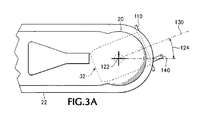
- the target housing body 108 may be attached to the mounting ball 36 or other support structure by a swivel defining an axis 122 parallel with the front, target face 110, so that the target body housing 108 may be moved through an angle 124 (see FIG. 3A ) about the axis 122 of the swivel to direct the front target face 110 toward the towing vehicle 26 while the towing vehicle is being backed into the hitch mating location, as will be described in greater detail presently.
- the swivel axis 122 should extend through the center of the target reticle 116.
- Small lamps 126 which may, for example, be LEDs, are provided in the top of the body housing 108 to shine upwardly and illuminate the tongue 20 and adjacent parts of the trailer 28 to assist in making the trailer 28 or other vehicle to be towed easily visible in the field of view of the camera 72 included in the towing vehicle module 30.
- This beam 130 of light is useful, as will be explained more fully presently, in initial preparation for backing the towing vehicle 26 toward the trailer 28 so as to place the towing vehicle in the required hitch-mating position for coupling the trailer hitch.
- a horizontal central opening 134 may be provided through the inclined target plate 114, and the projected light beam 130 is directed through that hole.
- the inclined target plate 114 may be imperforate, and the light beam projector 128 may be located within the housing 108 so that the beam 130 of light, after refraction by the inclined target plate 114, passes through the center 132 of the target front face 110.
- Appropriate electrical batteries 136 are provided within the target body housing 108 to power the lamps 120, 126 and the light beam projector 128, and appropriate switches 138 are provided to control operation of the lamps 120, 126 and the light beam projector 128.
- a small magnet 140 may be carried in a support such as a small telescoping tubular housing 142 which permits the magnet to extend forward a small distance, such as about 1 1 ⁇ 2 inches, from the target front face 110.
- the magnet 140 is located where it is aligned with the location of the magnetic reed switch 100 in the towing vehicle module 30 when the towing vehicle is located in the optimal hitch-mating position for mating the coupler 20 with the hitch ball 18.
- the trailer-mounted module 32 may be carried on a retractable and extendable support arm 142 mounted on the trailer tongue 22 as shown in FIG. 8 .
- a semicircular yoke 143 holds the trailer mounted module 32 on the arm 142 so that it can be rotated about the swivel axis 122, with the swivel axis extending through a point about which the trailer hitch coupling on the trailer 28 is rotatable with respect to the towing vehicle 26 when the trailer hitch parts are mated and ready for use.
- the towed vehicle module 32 is carried in the retracted position shown in broken line.
- the trailer-mounted, or towed vehicle, module 32 should be waterproof, so as to withstand immersion as when carried on a boat trailer during launching or recovery of a boat.
- a slide track 144 may be provided on the trailer tongue to hold the towed vehicle, or trailer-mounted, module 32.
- the trailer-mounted module 32 located as shown in solid line the reticle 116 on the inclined target plate 114 is centered below the coupler 20 for use.
- the module may be held by a swivel joint 145 so that it can be adjustably pivoted about the axis 122 as explained above.
- the module 32 can be withdrawn along the slide track 144 and carried in a retracted position and a front position of the slide track 144 may be telescoped back over the rear part, as shown in broken line in FIG. 8A , so as not to interfere with the trailer hitch ball 18 and socket 20.
- a telescoping support slide 146 for the towing vehicle module 30 may be mounted in a specifically provided storage location such as a protective compartment 147 in a rear end portion of the towing vehicle 26, adjacent the trailer hitch.
- the towing vehicle module 30 can be supported on the support slide 146, either retracted into the storage location, or with the slide 146 extended to a position in which the towing vehicle module 30 is located directly above the hitch ball 18. In the extended position as shown in solid line in FIG. 8A , the towing vehicle module 30 is used in the same manner as when mounted on the hitch ball 18 as shown in FIGS. 2-5 .
- the towed vehicle, or trailer-mounted, module 32 may be mounted as shown in FIGS. 8 and 8A as original equipment, or as after market equipment.
- the towing vehicle module 30 may also be mounted as shown in FIG. 8A as original equipment, or as an option for towing vehicles in which a rear end structure may include or may be modified easily to include a storage compartment 147.
- the video display device 34 may be mounted as seen in FIG. 9 , on the dashboard of the pickup truck or other towing vehicle 26, either as added equipment, or built into the dash of the towing vehicle 26 as original equipment, in which case it may be designed for multiple uses such as to display GPS mapping systems or other vehicle operational information of interest, as well as being electrically connected so that the monitor screen 74 is available additionally for use in connection with the hitch-alignment facilitating apparatus disclosed herein. It could also be built to interface with existing original equipment dash-mounted displays, portable monitors, laptop computers, or portable GPS and mobile telephone display units.
- the monitor screen 74 displays an image of the trailer 28 as seen by the camera 72 when the towing vehicle module 30 is properly mounted and adjusted, and with the towing vehicle 26 in position ahead of the trailer 28, ready to begin backing toward the trailer.
- the transparent front target face 110 of the trailer mounted, or target, module 32 is clearly visible, and the target reticle 116 on the inclined target plate 114 is also visible through the transparent front target face 110.
- the reticle 76 in the camera 72 is also visible in the monitor screen 74, as are the light beam, or spot, 68 which may be of a first color, for example red, projected from the lower or long distance guidance light beam projector 66 of the base portion 46 of the towing vehicle module 30 and another light beam, or spot, 92, which may optionally be of a second color such as green, projected by the upper, or short range guide light beam projector 90 carried in the upper portion 44 of the towing vehicle module 30.
- the light beams 68 and 92 may be projected as horizontal lines by the projector.
- the target, or trailer-mounted, module 32 is attached to the coupler 20 on the tongue 22 of the trailer 28 or other vehicle that is to be towed, and the towing vehicle module 30 is mounted on the trailer hitch ball 18 of the towing vehicle, as described and illustrated above.
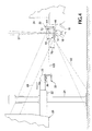
- the trailer-mounted module 32 When the trailer-mounted module 32 is level the swivel axis 122 is vertical, and the body or housing 108 is rotated about the swivel axis 122 until at an angle 124 the beam 130 of light from the light beam projector 128 is directed toward the towing vehicle module 30, as shown in FIGS. 3 , 3A , and 4 . If both the towing vehicle 26 and the vehicle 28 that is to be towed are on flat, level ground, the trailer tongue lift 24 can then be operated to bring the tongue 22 of the trailer 28 to a height at which the beam 130 of light projected from the light projector 128 is directed toward the lens of the camera 72 in the towing vehicle module 30.
- the trailer hitch coupler 20 This will place the trailer hitch coupler 20 at a preferred height to provide clearance for the base portion 46 of the towing vehicle module 30 to pass beneath the trailer-mounted module 32 of the hitch-guiding apparatus as the towing vehicle 26 is backed into the hitch-mating position.
- the height guidance light beam 130 can be turned off by the appropriate switch 138.
- the central axis of the field of view and the reticle 76 of the camera 72 should be aimed directly rearwardly as indicated by the right angle 152 in the horizontal plane, shown in FIG. 3 , and the laser or other light beams 68 and 92 from the guidance beam projectors 66 and 90 are then also directed rearwardly.
- the video camera 72 is then turned on, and its view is displayed as an image on the monitor screen 74 in the towing vehicle, in view of the vehicle operator, as shown in FIG. 9 .
- the towing vehicle 28 is then moved backward toward the tongue 22 of the trailer, which is clearly shown on the monitor screen 74.
- the towing vehicle 26 should be steered carefully to keep the target or towed vehicle module 32 centered in the image of the camera reticle 76 rather than to one side as shown in broken line.
- the light beam 68 from the long distance guidance light beam projector 66 will be visible where it impinges on the front of the trailer 28, once the towing vehicle is within several feet from the required position for connection of the trailer hitch coupler 20 to the trailer hitch ball 18.
- the distance where the light beam 68 can be observed is determined by the angle 70 at which the long distance guidance beam is oriented above horizontal, the length of the trailer tongue 22, and the height of a front surface of the trailer 28 on which the light beam 68 can fall.
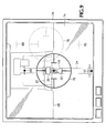
- the long distance guidance light beam 68 will move downward along the front of the trailer, while the image of the front target face 110 on the front of the towed vehicle module 32 will grow larger in the monitor screen 74 as the camera 72 moves closer to it, as shown in FIG. 10 .
- the towing vehicle 26 and the trailer 28 are separated by no more than a few feet, to confirm that the trailer tongue 22 is at the required height relative to the trailer hitch ball 18 on the towing vehicle, as by again operating the height adjustment light beam projector 128 and, if necessary, adjusting the lift 24 supporting the trailer tongue 22 so that the height adjustment light beam 130 is directed toward the lens of the camera 72.
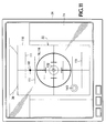
- the laser beam 68 from the long range guidance beam projector will impinge on the trailer at a location that appears to be vertically above the target front face 110, and as the towing vehicle module 30 approaches closer to the trailer mounted module 32 the long distance guidance light beam will become visible on the target front face 110 when the hitch ball 18 is several inches from the coupler 20, as shown in FIG. 11 .
- the upwardly inclined light beam 68 of the long distance guidance light beam projector 66 will strike the top of the front target calibrated graticule 111, indicating that the towing vehicle is closely approaching the hitch mating location. If the trailer hitch coupler 20 is adjusted correctly in height the horizontal lines of the graticule 111 will give an accurate indication of the distance through which the towing vehicle 26 still needs to move rearwardly to the desired hitch-mating position.
- the beam 68 will move downward along the front target face 110 as the base portion 46 of the towing vehicle module 30 approaches the front target face 110 until the lower light beam 68 progresses down to the bottom of the front target face 110 just before the base portion 46 of the towing vehicle module 30 passes beneath the target face 110. It should be apparent to the towing vehicle operator viewing the monitor screen 74 if the height of the trailer tongue is not correct, as the center 132 of the front target face 110 will appear to be too high in the lens reticle 76 of the camera 72 if the trailer tongue 22 is too high, or will appear too low in the lens reticle 76 field of view of the camera 72 if the trailer tongue 22 is too low.
- the operator should stop backing toward the trailer 28 and adjust the height of the trailer tongue 22 to be sure that the towing vehicle hitch ball will be able to pass properly beneath the tongue of the trailer, and that the base portion 46 of the towing vehicle module 30 can pass beneath the target, or towed vehicle module 30.
- the downwardly inclined light beam 92 from the short range guidance light beam projector 90 at the top of the upper part 44 of the towing vehicle module 30 should become visible at the bottom of the front target face 110 if the trailer tongue 22 is at the correct height with respect to the trailer hitch ball 18 on the towing vehicle.
- the green laser beam 92 of the upper laser light beam projector 90 is visible on the front target calibrated graticule 111 the towing vehicle 26 is very close, within about two inches, to the desired hitch-mating location.
- the light beam 57 from upwardly directed hitch alignment light beam projector 56 in the base portion 46 of the towing vehicle module 30 should then be visible to the camera 72 at the top of the inclined target plate 114 within the towed vehicle module 32, as shown in broken line in FIG. 7 .
- the magnet 140 may activate the reed switch 100, causing an audible signal to be sounded by the display device 34.
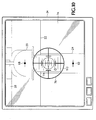
- the laser beam 57 will appear to move down across the target reticle 116 defined on the inclined etched target plate 114, until, when the towing vehicle is in the correct position, as shown in FIG. 12 the laser beam 57 will appear to be centered in the target on the inclined etched target plate.
- the towing vehicle operator should then stop the towing vehicle 26, set its brakes, and then remove both modules 30 and 32 of the hitch guidance apparatus from their respective places on the towing vehicle trailer hitch ball 18 and the trailer hitch coupler 20 and then lower the trailer tongue 22 to mate the coupler 20 with the trailer hitch ball 18.
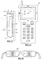
- the principal utility of the apparatus described above is in enhancing the ability to back a towing vehicle 26 easily and accurately to a mating location where a trailer hitch can be coupled, the ability to transmit a video image wirelessly from the camera 72 to the monitor screen 74 near the towing vehicle driver's position makes the upper portion 44 of the towing vehicle module 30 otherwise conveniently useful, both in connection with backing the trailer 28 and while towing the trailer 28 along a highway. Since the upper portion 44 of the towing vehicle module 30 can be removed from the base portion 46 by use of the quick disconnect coupling 48, the upper part 44 can be mounted on the rear of the trailer 28, as shown in FIG. 13 , either by use of the suction cups 86 or by the use of an appropriate hanger (not shown) and the hanger receivers 84.
- Video images from the camera 72 can then be transmitted wirelessly to the display device 34 in the towing vehicle 26, so that the driver of the towing vehicle can see what is behind the trailer 28 as the trailer is backed into a parking position, making it much easier to park the trailer safely. Additionally, the camera 72, when mounted on the back of the trailer 28, can be used while towing the trailer along a highway, to provide a much better view of vehicles following the trailer 28 than is normally available simply by using ordinary side view mirrors on the towing vehicle 26.
- the camera 72 can be used by a person carrying the unit to transmit a view to the video display device 34 in the towing vehicle 26.
- a suitable wireless receiver and antenna capable of receiving the transmitted signal from the towing vehicle module and providing both audio and video output signals to the monitor, may be connected with the monitor.
- the towing vehicle module 30 can include a Global Positioning System (GPS) satellite unit and a beacon transmitter 148 contained in the upper portion 44, as shown in simplified form in FIG. 5 .
- GPS Global Positioning System
- the GPS navigation system may be designed to communicate with commercially available satellite radio and mapping services.
- the GPS unit included in the upper portion 44 can thus be carried by a person venturing away from the location of the towing vehicle 26, as when the towing vehicle 26 is left in a camp and a person hikes into nearby wilderness, where the beacon transmitter, coupled with the GPS unit in the upper portion 44, is available as an emergency beacon transmitting its location in case the user is injured or becomes disoriented.
- a separate handheld mobile telephone and beacon monitor unit 150 may be used to determine and display the location of a person carrying the upper part of the towing vehicle module. This acts as a safety feature in conjunction with use of the upper portion 44 of the towing vehicle module 30, which, in one embodiment of the device, may include a low power radio telephone able to conduct two-way communications with such a separate self-contained handheld unit 150.
- the handheld unit 150 may include circuitry capable of utilizing existing cellular or satellite mobile telephone or wireless computer communications systems to receive and display the GPS beacon data showing the location 154 of the upper portion 44 of the towing vehicle module 30 carried by a person at some distance from the towing vehicle in which the video display device 34 is installed and operated.
- the beacon monitor unit could thus be used with appropriate identifying codes to locate the upper portion 44 either locally or at great distances, depending on the associated communication system used.
- the monitor screen 74 of the display device 34 in the towing vehicle 26 may be equipped and programmed with a touch screen control interface for use in connection with programming a GPS navigation system setting to synchronize the display device 34 and the upper portion 44 of the towing vehicle module 30 with a satellite navigation system in connection with monitoring the location of the portable upper portion 44 of the towing vehicle module 30.
- a portable, wearable visual display may be provided by a wearable display device 156 similar to a pair of virtual reality glasses known for use in connection with video computer gaming technology.
- One or two video display devices 34 may be provided in the wearable display device 156 for use instead of or as well as the dash-mounted video monitor screen 74, to provide an image from the video camera 72 to the operator of the towing vehicle 26, while the towing vehicle is backed into position for mating the trailer 28 to the towing vehicle 26.
Landscapes
- Engineering & Computer Science (AREA)
- Transportation (AREA)
- Mechanical Engineering (AREA)
- Fittings On The Vehicle Exterior For Carrying Loads, And Devices For Holding Or Mounting Articles (AREA)
Claims (13)
- Gerät zum Anleiten eines Führers eines Abschleppfahrzeugs, das in Bezug auf ein abzuschleppendes Fahrzeug rückwärts hin zu einer angekuppelten Position gefahren wird, umfassend:(a) eine nach hinten gerichtete Videobilderzeugungsvorrichtung (72), die am Abschleppfahrzeug (26) mitgeführt wird;(b) eine die Ausrichtung anzeigende Lichtstrahlprojektionsvorrichtung (56), die am Abschleppfahrzeug (26) montiert ist;(c) eine Videoanzeigevorrichtung (34, 74), die für den Führer des Abschleppfahrzeugs (26) sichtbar und so angeordnet ist, dass ein von der Videobildgebungsvorrichtung (72) erzeugtes Bild angezeigt wird; und(d) ein Ziel (32), das am abzuschleppenden Fahrzeug in einer Position montiert ist, wo ein Lichtstrahl (57) von der Projektionsvorrichtung (56) auf das Ziel (32) fällt und sich das Ziel (32) innerhalb des Sichtfelds der Videobilderzeugungsvorrichtung befindet, wenn sich das Abschleppfahrzeug (26) in Bezug auf das abzuschleppende Fahrzeug (28) nahe bei einer angekuppelten Position befindet, dadurch gekennzeichnet, dass die Lichtstrahlprojektionsvorrichtung (56) einen Kleinleistungslaser beinhaltet und der Laser auf eine Kupplungskugel montiert und nach oben gerichtet ist, und wobei das Ziel (32) eine geneigte Zieltafel (114) beinhaltet, die so positioniert ist, dass ein Lichtstrahl aus dem Laser auf sie trifft, wenn sich das Abschleppfahrzeug (26) nahe bei besagter angekuppelter Position befindet.
- Gerät nach Anspruch 1, wobei:das Ziel (32) in einer anhängermontierten Vorrichtung (32) enthalten ist, die einen Lichtstrahlprojektor (128) beinhaltet und verstellbar beweglich ist, um einen Lichtstrahl hin zu einer vorbestimmten Position am Abschleppfahrzeug (26) zu projizieren; ODERdie geneigte Zieltafel (114) in einer anhängermontierten Vorrichtung (32) enthalten ist, die am Anhänger (28) unterhalb eines Kupplungsteils (20) einer Anhängerkupplung angebracht ist.
- Vorrichtung nach Anspruch 1, wobei:die Bilderzeugungsvorrichtung (72) eine digitale Videokamera ist; ODER die Bilderzeugungsvorrichtung (72) eine digitale Videokamera ist und besagte digitale Videokamera mit einem drahtlosen Signalübertrager assoziiert ist, der so angeordnet ist, dass besagtes Bild an besagte Videoanzeigevorrichtung (34, 74) übertragen wird.
- Gerät nach Anspruch 1, wobei die Videobilderzeugungsvorrichtung (72) vom Abschleppfahrzeug (26) abnehmbar und fernbedienbar ist, um ein Videobild drahtlos an besagte Videoanzeigevorrichtung (34, 74) zu übertragen.
- Gerät nach Anspruch 1 einschließlich eines Lichtstrahlprojektors mit Langstreckenführung (66), der so angeordnet ist, dass ein Strahl (68) Licht nach hinten vom Abschleppfahrzeug (26) aus in einem spitzen Winkel (70) oberhalb einer horizontalen Ebene projiziert wird, damit er sichtbar auf eine vordere Oberfläche des abzuschleppenden Fahrzeugs (28) fällt.
- Gerät nach Anspruch 5, wobei das Ziel (32) eine vordere Zielfläche (110) beinhaltet, die sich dort befindet, wo besagter Strahl (68) Licht aus besagtem Lichtstrahlprojektor mit Langstreckenführung (66) sichtbar auf die vordere Zielfläche fällt, wenn sich das Abschleppfahrzeug (26) der angekuppelten Position bis auf einen vorbestimmten Abstand nähert.
- Gerät nach Anspruch 6, wobei die vordere Zielfläche (110) ein kalibriertes Abstandsschätzungsraster beinhaltet.
- Gerät nach Anspruch 6 einschließlich eines Lichtstrahlprojektors mit Kurzstreckenführung (90), der so angeordnet ist, dass ein Strahl (92) Licht in einem spitzen Winkel (94) unterhalb einer horizontalen Ebene projiziert wird, sodass besagter Strahl (92) Licht daraus sichtbar auf besagte vordere Zielfläche (110) fällt, wenn besagtes Abschleppfahrzeug (26) bis auf einen vorbestimmten kurzen Abstand von besagter angekuppelter Position entfernt ist.
- Vorrichtung nach Anspruch 1, wobei:besagte Bilderzeugungsvorrichtung (72) eine Videokamera einschließlich eines Fadenkreuzes (76) ist, das in einem von besagter Kamera erzeugten Bild sichtbar ist; ODERbesagte Videoanzeigevorrichtung (34, 74) eine Videobildanzeige (156) beinhaltet, die so angeordnet ist, dass sie am Kopf des besagten Führers getragen wird, um sichtbar zu sein, ohne dass besagter Führer den Kopf drehen muss.
- Vorrichtung nach Anspruch 1, wobei:(a) die die Ausrichtung anzeigende Lichtstrahlprojektionsvorrichtung (56) angeordnet ist, um den Strahl (57) Licht nach oben oberhalb einer Schwenkachse zu projizieren, die vom am Abschleppfahrzeug (26) mitgeführten Anhängerkupplungsteil (18) definiert wird;(b) sich das Ziel (32) unterhalb einer Hitchkupplung (20) an einem abzuschleppenden Fahrzeug (28) befindet;(c) die Videobilderzeugungsvorrichtung (72) eine Kamera ist, die am Abschleppfahrzeug (26) an einer Stelle mitgeführt wird, wo die Kamera ein Bild des Ziels (32) erzeugen kann, wenn das Abschleppfahrzeug (26) vor dem abzuschleppenden Fahrzeug (28) positioniert ist und in Bezug auf besagtes abzuschleppendes Fahrzeug zum Rückwärtsfahren in die angekuppelte Position bereit ist; und(d) die Videobildanzeigevorrichtung (72) für den Führer des Abschleppfahrzeugs (26) sichtbar und so angeordnet ist, dass ein Bild mindestens eines Teils eines Sichtfelds der Kamera angezeigt wird.
- Vorrichtung nach Anspruch 10:einschließlich eines Lichtstrahlprojektors mit Langstreckenführung (66), der am Abschleppfahrzeug (26) montiert ist und einen den Abstand schätzenden Lichtstrahl (68) in einem vorbestimmten nach oben geneigten Winkel und hin zum abzuschleppenden Fahrzeug (28) projiziert; ODEReinschließlich eines Lichtstrahlprojektors mit Langstreckenführung (66), der am Abschleppfahrzeug (26) montiert ist und einen den Abstand schätzenden Lichtstrahl (68) in einem vorbestimmten nach oben geneigten Winkel und hin zum abzuschleppenden Fahrzeug (28) projiziert und wobei besagter Lichtstrahl mit Langstreckenführung (68) vom Abschleppfahrzeug (28) aus direkt nach hinten gerichtet wird; ODERwobei die Kamera ein Bild eines Fadenkreuzes (76) bereitstellt, das mit ihrem Sichtfeld ausgerichtet ist.
- Verfahren zum Bewegen eines Abschleppfahrzeugs in eine gewünschte angekuppelte Position in Bezug auf einen Anhänger, umfassend:(a) Bereitstellen einer Videokamera (72) am Abschleppfahrzeug (26) nahe bei einem Anhängerkupplungsteil (18), das mit einer Anhänger-Hitchkupplung (20), die mit einer Zunge (22) des Anhängers (28) verbunden ist, zusammenzufügen ist;(b) Bereitstellen eines visuellen Ziels (32) nahe bei der Anhänger-Hitchkupplung (20), die mit der Zunge (22) des Anhängers (28) verbunden ist;(c) Beobachten eines Videobilds des Ziels auf einer Videobildgebungsvorrichtung (34, 74) während des Betriebs des Abschleppfahrzeugs (26);(d) Bewegen des Abschleppfahrzeugs (26) nach hinten hin zur Anhänger-Hitchkupplung bei gleichzeitigem Beobachten des Videobilds;(e) Projizieren eines Strahls (57) Licht direkt nach oben von einer Stelle am Abschleppfahrzeug (26) nahe bei der Anhängerkupplung;(f) Lenken des Abschleppfahrzeugs (26) als Reaktion auf das Betrachten des Videobilds, bei gleichzeitigem Bewegen des Abschleppfahrzeug nach hinten, bis der nach oben gerichtete Strahl (57) Licht auf ein geneigtes Zielelement (114) fällt, das nahe bei der Anhänger-Hitchkupplung (20) montiert ist; und(g) Beobachten eines Videobilds des geneigten Zielelements (114) einschließlich eines Bilds des nach oben gerichteten Strahls (54) Licht, der auf das geneigte Zielelement (114) fällt, bei gleichzeitigem Weiterbewegen des Abschleppfahrzeugs (26) hin zur gewünschten angekuppelten Position für das Zusammenfügen der Zunge (22) des abzuschleppenden Fahrzeugs mit der Anhängerkupplung am Abschleppfahrzeug (26), und Bewegen des Abschleppfahrzeugs (26) hin zur angekuppelten Position als Reaktion darauf, bis besagter nach oben gerichteter Strahl (57) Licht beobachtbar auf einen vorbestimmten Teil des geneigten Zielelements (114) trifft.
- Verfahren nach Anspruch 12 einschließlich:des Schritts des Projizierens eines zweiten Lichtstrahls nach hinten vom Abschleppfahrzeug (26) aus und in einem vorbestimmten spitzen Winkel in Bezug auf eine horizontale Ebene, wobei in besagtem Videobild eine Stelle beobachtet wird, wo der Lichtstrahl auf den Anhänger (28) trifft, und wodurch ein Abstand zwischen dem Abschleppfahrzeug (26) und dem Anhänger (28) geschätzt wird; ODERdes Schritts des Mitführens der besagten Videokamera an besagtem Anhängerkupplungsteil (18) des Abschleppfahrzeugs (26); ODERdes Schritts des Orientierens des geneigten Zielelements (114) an der Anhängerzunge (22), damit es hin zum Abschleppfahrzeug (26) zeigt, bevor das Abschleppfahrzeug (26) näher als einen vorbestimmten Abstand von der Zunge (22) des Anhängers (28) bewegt wird; ODERdes Schritts des Platzierens der Videokamera in einer vorbestimmten Orientierung in Bezug auf das Abschleppfahrzeug (26), bevor das Abschleppfahrzeug (26) näher als einen vorbestimmten Abstand zur Anhängerzunge (22) bewegt wird; ODERdie Schritte des Projizierens eines zweiten Lichtstrahls nach hinten vom Abschleppfahrzeug (26) aus in einem Winkel, der in einem vorbestimmten Winkel nach oben oberhalb der Horizontalen geneigt ist, und Beobachten im Videobild, wo der zweite Lichtstrahl auf den Anhänger (28) fällt, da das Abschleppfahrzeug (26) sich dem Anhänger (28) nähert, und Führen des Abschleppfahrzeugs (26) als Reaktion darauf.
Applications Claiming Priority (2)
| Application Number | Priority Date | Filing Date | Title |
|---|---|---|---|
| US11/698,708 US8888120B2 (en) | 2007-01-25 | 2007-01-25 | Towing vehicle guidance for trailer hitch connection |
| PCT/US2008/000704 WO2008091549A1 (en) | 2007-01-25 | 2008-01-18 | Towing vehicle guidance for trailer hitch connection |
Publications (3)
| Publication Number | Publication Date |
|---|---|
| EP2155507A1 EP2155507A1 (de) | 2010-02-24 |
| EP2155507A4 EP2155507A4 (de) | 2011-03-09 |
| EP2155507B1 true EP2155507B1 (de) | 2014-08-27 |
Family
ID=39644786
Family Applications (1)
| Application Number | Title | Priority Date | Filing Date |
|---|---|---|---|
| EP08724631.0A Not-in-force EP2155507B1 (de) | 2007-01-25 | 2008-01-18 | Abschleppfahrzeugführung für eine anhängerkupplung |
Country Status (3)
| Country | Link |
|---|---|
| US (1) | US8888120B2 (de) |
| EP (1) | EP2155507B1 (de) |
| WO (1) | WO2008091549A1 (de) |
Cited By (6)
| Publication number | Priority date | Publication date | Assignee | Title |
|---|---|---|---|---|
| US10670479B2 (en) | 2018-02-27 | 2020-06-02 | Methode Electronics, Inc. | Towing systems and methods using magnetic field sensing |
| US10696109B2 (en) | 2017-03-22 | 2020-06-30 | Methode Electronics Malta Ltd. | Magnetolastic based sensor assembly |
| US11084342B2 (en) | 2018-02-27 | 2021-08-10 | Methode Electronics, Inc. | Towing systems and methods using magnetic field sensing |
| US11135882B2 (en) | 2018-02-27 | 2021-10-05 | Methode Electronics, Inc. | Towing systems and methods using magnetic field sensing |
| US11221262B2 (en) | 2018-02-27 | 2022-01-11 | Methode Electronics, Inc. | Towing systems and methods using magnetic field sensing |
| US11491832B2 (en) | 2018-02-27 | 2022-11-08 | Methode Electronics, Inc. | Towing systems and methods using magnetic field sensing |
Families Citing this family (96)
| Publication number | Priority date | Publication date | Assignee | Title |
|---|---|---|---|---|
| US20070205875A1 (en) * | 2006-03-03 | 2007-09-06 | De Haan Ido G | Auxiliary device with projection display information alert |
| US8888121B2 (en) * | 2007-01-25 | 2014-11-18 | Target Hitch Llc | Towing vehicle guidance for trailer hitch connection |
| GB2447672B (en) | 2007-03-21 | 2011-12-14 | Ford Global Tech Llc | Vehicle manoeuvring aids |
| US20080266397A1 (en) * | 2007-04-25 | 2008-10-30 | Navaratne Dombawela | Accident witness |
| US7777615B2 (en) * | 2008-03-20 | 2010-08-17 | Toyota Motor Engineering & Manufacturing North America, Inc. | System for assisting the attachment of a trailer to a vehicle |
| US20090271078A1 (en) * | 2008-04-29 | 2009-10-29 | Mike Dickinson | System and method for identifying a trailer being towed by a vehicle |
| JP5256899B2 (ja) * | 2008-07-18 | 2013-08-07 | セイコーエプソン株式会社 | 画像補正装置、画像補正方法、プロジェクタおよびプロジェクションシステム |
| GB2469438B (en) * | 2009-03-09 | 2014-04-09 | Applic Solutions Electronics & Vision Ltd | Display movement of an object |
| NL1036850C2 (nl) * | 2009-04-14 | 2010-10-18 | Lex Elzo Westera | Aankoppelhulp. |
| US9440591B2 (en) * | 2009-05-13 | 2016-09-13 | Deere & Company | Enhanced visibility system |
| WO2011014497A1 (en) | 2009-07-27 | 2011-02-03 | Magna Electronics Inc. | Vehicular camera with on-board microcontroller |
| DE102010053818A1 (de) * | 2010-12-08 | 2012-06-14 | Audi Ag | Verfahren und Vorrichtung zur Erkennung eines Anhängers eines Kraftfahrzeugs |
| US20120229639A1 (en) * | 2011-03-09 | 2012-09-13 | Ronald Singleton | Truck Bed Monitoring System |
| US9513103B2 (en) | 2011-04-19 | 2016-12-06 | Ford Global Technologies, Llc | Hitch angle sensor assembly |
| US9854209B2 (en) | 2011-04-19 | 2017-12-26 | Ford Global Technologies, Llc | Display system utilizing vehicle and trailer dynamics |
| US9937953B2 (en) | 2011-04-19 | 2018-04-10 | Ford Global Technologies, Llc | Trailer backup offset determination |
| US9102271B2 (en) | 2011-04-19 | 2015-08-11 | Ford Global Technologies, Llc | Trailer monitoring system and method |
| US9683848B2 (en) | 2011-04-19 | 2017-06-20 | Ford Global Technologies, Llc | System for determining hitch angle |
| US9723274B2 (en) | 2011-04-19 | 2017-08-01 | Ford Global Technologies, Llc | System and method for adjusting an image capture setting |
| US9102272B2 (en) | 2011-04-19 | 2015-08-11 | Ford Global Technologies, Llc | Trailer target monitoring system and method |
| US9969428B2 (en) | 2011-04-19 | 2018-05-15 | Ford Global Technologies, Llc | Trailer backup assist system with waypoint selection |
| US9926008B2 (en) | 2011-04-19 | 2018-03-27 | Ford Global Technologies, Llc | Trailer backup assist system with waypoint selection |
| US9296422B2 (en) | 2011-04-19 | 2016-03-29 | Ford Global Technologies, Llc | Trailer angle detection target plausibility |
| US9374562B2 (en) | 2011-04-19 | 2016-06-21 | Ford Global Technologies, Llc | System and method for calculating a horizontal camera to target distance |
| US9290204B2 (en) | 2011-04-19 | 2016-03-22 | Ford Global Technologies, Llc | Hitch angle monitoring system and method |
| US9500497B2 (en) | 2011-04-19 | 2016-11-22 | Ford Global Technologies, Llc | System and method of inputting an intended backing path |
| US10196088B2 (en) | 2011-04-19 | 2019-02-05 | Ford Global Technologies, Llc | Target monitoring system and method |
| US8930140B2 (en) | 2011-04-19 | 2015-01-06 | Ford Global Technologies, Llc | Trailer target placement assist system and method |
| US9555832B2 (en) | 2011-04-19 | 2017-01-31 | Ford Global Technologies, Llc | Display system utilizing vehicle and trailer dynamics |
| US9346396B2 (en) | 2011-04-19 | 2016-05-24 | Ford Global Technologies, Llc | Supplemental vehicle lighting system for vision based target detection |
| US9506774B2 (en) | 2011-04-19 | 2016-11-29 | Ford Global Technologies, Llc | Method of inputting a path for a vehicle and trailer |
| US9283892B2 (en) * | 2011-04-19 | 2016-03-15 | Ford Global Technologies, Llc | Method and system for monitoring placement of a target on a trailer |
| US8365422B1 (en) * | 2012-01-05 | 2013-02-05 | Charles Lawrence Ott | Tru-hitchin using dual beam technology and triangulation |
| US8976246B1 (en) | 2012-04-03 | 2015-03-10 | Michael E. Rappuhn | Gooseneck or fifth wheel trailer hitch alignment and safety system |
| US9511799B2 (en) | 2013-02-04 | 2016-12-06 | Ford Global Technologies, Llc | Object avoidance for a trailer backup assist system |
| US9592851B2 (en) | 2013-02-04 | 2017-03-14 | Ford Global Technologies, Llc | Control modes for a trailer backup assist system |
| US10755110B2 (en) | 2013-06-28 | 2020-08-25 | Magna Electronics Inc. | Trailering assist system for vehicle |
| NO20130966A1 (no) * | 2013-07-11 | 2015-01-12 | Smart Patents As | System og fremgangsmåte for automatisk å koble en tilhenger til et kjøretøy |
| US9037312B2 (en) | 2013-08-26 | 2015-05-19 | Ford Global Technologies | Trailer heading angle using vehicle wheel speed sensors |
| US20150108736A1 (en) * | 2013-10-17 | 2015-04-23 | Joseph P. Jamieson | Trailer autoconnect system |
| US9352777B2 (en) * | 2013-10-31 | 2016-05-31 | Ford Global Technologies, Llc | Methods and systems for configuring of a trailer maneuvering system |
| US9464886B2 (en) | 2013-11-21 | 2016-10-11 | Ford Global Technologies, Llc | Luminescent hitch angle detection component |
| US9464887B2 (en) | 2013-11-21 | 2016-10-11 | Ford Global Technologies, Llc | Illuminated hitch angle detection component |
| US9233710B2 (en) | 2014-03-06 | 2016-01-12 | Ford Global Technologies, Llc | Trailer backup assist system using gesture commands and method |
| US9296421B2 (en) | 2014-03-06 | 2016-03-29 | Ford Global Technologies, Llc | Vehicle target identification using human gesture recognition |
| DE102014108484B4 (de) * | 2014-06-17 | 2021-07-01 | Robert Bosch Gmbh | Verfahren zur unterstützung eines fahrers beim rangieren eines kraftfahrzeuggespanns |
| US9517668B2 (en) | 2014-07-28 | 2016-12-13 | Ford Global Technologies, Llc | Hitch angle warning system and method |
| US9963004B2 (en) | 2014-07-28 | 2018-05-08 | Ford Global Technologies, Llc | Trailer sway warning system and method |
| US10112537B2 (en) | 2014-09-03 | 2018-10-30 | Ford Global Technologies, Llc | Trailer angle detection target fade warning |
| US9950758B2 (en) * | 2014-09-17 | 2018-04-24 | General Electric Company | Systems and methods for a turbine trailer mechanical docking and alignment system |
| US9522677B2 (en) | 2014-12-05 | 2016-12-20 | Ford Global Technologies, Llc | Mitigation of input device failure and mode management |
| US9533683B2 (en) | 2014-12-05 | 2017-01-03 | Ford Global Technologies, Llc | Sensor failure mitigation system and mode management |
| US9607242B2 (en) * | 2015-01-16 | 2017-03-28 | Ford Global Technologies, Llc | Target monitoring system with lens cleaning device |
| US9522699B2 (en) | 2015-02-05 | 2016-12-20 | Ford Global Technologies, Llc | Trailer backup assist system with adaptive steering angle limits |
| US9616923B2 (en) | 2015-03-03 | 2017-04-11 | Ford Global Technologies, Llc | Topographical integration for trailer backup assist system |
| US9804022B2 (en) | 2015-03-24 | 2017-10-31 | Ford Global Technologies, Llc | System and method for hitch angle detection |
| US9499018B2 (en) | 2015-04-01 | 2016-11-22 | Robert Bosch Gmbh | Trailer coupling assistance system with vehicle video camera |
| US9849864B2 (en) | 2015-07-31 | 2017-12-26 | Ford Global Technologies, Llc | Vehicle parking assist system |
| US9896130B2 (en) | 2015-09-11 | 2018-02-20 | Ford Global Technologies, Llc | Guidance system for a vehicle reversing a trailer along an intended backing path |
| US9981656B2 (en) | 2015-10-13 | 2018-05-29 | Ford Global Technologies, Llc | Vehicle parking assist system |
| US10611407B2 (en) | 2015-10-19 | 2020-04-07 | Ford Global Technologies, Llc | Speed control for motor vehicles |
| US10384607B2 (en) | 2015-10-19 | 2019-08-20 | Ford Global Technologies, Llc | Trailer backup assist system with hitch angle offset estimation |
| US9836060B2 (en) | 2015-10-28 | 2017-12-05 | Ford Global Technologies, Llc | Trailer backup assist system with target management |
| US10328933B2 (en) | 2015-10-29 | 2019-06-25 | Ford Global Technologies, Llc | Cognitive reverse speed limiting |
| US10017115B2 (en) | 2015-11-11 | 2018-07-10 | Ford Global Technologies, Llc | Trailer monitoring system and method |
| US10155478B2 (en) | 2015-12-17 | 2018-12-18 | Ford Global Technologies, Llc | Centerline method for trailer hitch angle detection |
| US9827818B2 (en) | 2015-12-17 | 2017-11-28 | Ford Global Technologies, Llc | Multi-stage solution for trailer hitch angle initialization |
| US9934572B2 (en) | 2015-12-17 | 2018-04-03 | Ford Global Technologies, Llc | Drawbar scan solution for locating trailer hitch point |
| US9610975B1 (en) | 2015-12-17 | 2017-04-04 | Ford Global Technologies, Llc | Hitch angle detection for trailer backup assist system |
| US9798953B2 (en) | 2015-12-17 | 2017-10-24 | Ford Global Technologies, Llc | Template matching solution for locating trailer hitch point |
| US10005492B2 (en) | 2016-02-18 | 2018-06-26 | Ford Global Technologies, Llc | Trailer length and hitch angle bias estimation |
| US9669771B1 (en) | 2016-02-19 | 2017-06-06 | Toyota Motor Engineering & Manufacturing North America, Inc. | Gravity mount and rotational securement for sensing element |
| US10112646B2 (en) | 2016-05-05 | 2018-10-30 | Ford Global Technologies, Llc | Turn recovery human machine interface for trailer backup assist |
| US10106193B2 (en) | 2016-07-01 | 2018-10-23 | Ford Global Technologies, Llc | Enhanced yaw rate trailer angle detection initialization |
| US10864787B2 (en) | 2016-07-28 | 2020-12-15 | Robert Bosch Gmbh | Systems and methods for a human machine interface for a trailer hitch system |
| US10046800B2 (en) | 2016-08-10 | 2018-08-14 | Ford Global Technologies, Llc | Trailer wheel targetless trailer angle detection |
| US10222804B2 (en) | 2016-10-21 | 2019-03-05 | Ford Global Technologies, Llc | Inertial reference for TBA speed limiting |
| CA2989345C (en) * | 2016-12-16 | 2021-11-02 | Safe Rack Llc | Pivotal gangway having container spotting system |
| US10457205B2 (en) * | 2017-03-16 | 2019-10-29 | Robotzone, Llc | Assisted trailer alignment system |
| US10710585B2 (en) | 2017-09-01 | 2020-07-14 | Ford Global Technologies, Llc | Trailer backup assist system with predictive hitch angle functionality |
| US10802478B2 (en) * | 2017-10-19 | 2020-10-13 | Ford Global Technologies, Llc | Hitch assist system and method for autonomously maneuvering a vehicle in a user-specified target travel direction |
| US11014417B2 (en) | 2018-02-27 | 2021-05-25 | Methode Electronics, Inc. | Towing systems and methods using magnetic field sensing |
| US11090990B2 (en) * | 2018-09-17 | 2021-08-17 | Ford Global Technologies, Llc | Trailer position, heading angle, and level measurement with smart device |
| US11077795B2 (en) | 2018-11-26 | 2021-08-03 | Ford Global Technologies, Llc | Trailer angle detection using end-to-end learning |
| US11030476B2 (en) * | 2018-11-29 | 2021-06-08 | Element Ai Inc. | System and method for detecting and tracking objects |
| US10864848B2 (en) * | 2018-12-21 | 2020-12-15 | Continental Automotive Systems, Inc. | Reverse lights trailer hitch assist |
| US10829046B2 (en) | 2019-03-06 | 2020-11-10 | Ford Global Technologies, Llc | Trailer angle detection using end-to-end learning |
| EP3947112B1 (de) * | 2019-03-25 | 2024-05-08 | Volvo Truck Corporation | Fahrzeug mit einem anhängerwinkelbestimmungssystem |
| US11851061B2 (en) | 2019-08-26 | 2023-12-26 | Ford Global Technologies, Llc | Prevention of trailer coupler tracking jump during hitch assist operation |
| US11155298B2 (en) | 2019-09-03 | 2021-10-26 | Ford Global Technologies, Llc | Modified steering angle at completion of hitch assist operation |
| US11697414B2 (en) | 2020-03-17 | 2023-07-11 | Ford Global Technologies, Llc | System and method for remote automated vehicle alignment with a trailer for hitching |
| US12078504B2 (en) * | 2020-10-14 | 2024-09-03 | Sam Carbis Asset Management, Llc | Loading dock alignment system |
| JP7587817B2 (ja) * | 2020-11-27 | 2024-11-21 | 株式会社イシダ | 物品処理装置及び下流側装置 |
| CN115328151B (zh) * | 2022-08-30 | 2025-03-21 | 浙江吉利控股集团有限公司 | 牵引车对接辅助方法、装置、设备及存储介质 |
| DE102022003318B4 (de) * | 2022-09-09 | 2026-05-07 | Jost-Werke Deutschland Gmbh | Ausrichtsystem zur annäherung eines fahrzeugs an ein hierzu räumlich beabstandetes zielobjekt |
| CN116090239A (zh) * | 2023-01-31 | 2023-05-09 | 奇瑞汽车股份有限公司 | 一种汽车拖钩牵引性分析方法、系统、设备和可读存储介质 |
Family Cites Families (44)
| Publication number | Priority date | Publication date | Assignee | Title |
|---|---|---|---|---|
| US4552376A (en) * | 1983-11-16 | 1985-11-12 | Archie Cofer | Trailer hitch lamp guide |
| US5112172A (en) | 1990-09-12 | 1992-05-12 | Knorr Brake Holding Corporation | Sliding pull up stanchion and method |
| GB2277721B (en) | 1993-05-08 | 1997-04-23 | Keith Michael Sommerfeld | Optical ranging |
| US5650764A (en) | 1994-08-25 | 1997-07-22 | Mccullough; Deborah Y. | Trailer alignment device with visual display |
| US5513870A (en) * | 1995-05-24 | 1996-05-07 | Hickman; Herbert D. | Guidance system for use in docking a movable vehicle with a stationary target |
| US5729194A (en) | 1996-11-26 | 1998-03-17 | Spears; Dan E. | Backup system to position vehicle relative to stationary trailer during backing procedure |
| US5951035A (en) | 1997-03-11 | 1999-09-14 | Phillips, Jr.; Robert E. | Trailer hitch alignment system |
| US6252497B1 (en) * | 1997-10-16 | 2001-06-26 | Holland Hitch Company | Coupling alignment warning system |
| US6592230B2 (en) | 1997-10-16 | 2003-07-15 | Holland Hitch Company | Truck rearview mirror assembly having a display for displaying trailer coupling status information |
| US6120052A (en) | 1998-01-15 | 2000-09-19 | Capik; Dan | Optically guided trailer hitching system |
| US6693524B1 (en) | 1998-06-02 | 2004-02-17 | George R. Payne | Vehicle backup monitoring and alarm system |
| US6100795A (en) | 1999-03-12 | 2000-08-08 | Otterbacher; Curtis W. | Trailer hitch alignment system |
| US6225895B1 (en) | 1999-05-26 | 2001-05-01 | Floyd E. Bigelow, Jr. | Towed vehicle monitor system |
| US6178650B1 (en) | 1999-07-14 | 2001-01-30 | Joseph I. Thibodeaux | Trailer hitch positioning system |
| EP1785336B1 (de) | 1999-08-12 | 2008-03-26 | Kabushiki Kaisha Toyota Jidoshokki | Lenkhilfseinrichtung |
| US6222457B1 (en) | 1999-10-12 | 2001-04-24 | Stephen Scott Keneally | Electronic trailer hitching system |
| US6259357B1 (en) | 1999-12-30 | 2001-07-10 | Joseph Heider | Trailer hitch positioning apparatus |
| WO2001064480A2 (en) | 2000-02-28 | 2001-09-07 | Milliken Franklin L | Vehicle back up alarm with integral back up light |
| US6977584B2 (en) | 2000-02-28 | 2005-12-20 | Milliken Franklin L | Vehicle back up alarm with associated back up light |
| US20010045978A1 (en) | 2000-04-12 | 2001-11-29 | Mcconnell Daniel L. | Portable personal wireless interactive video device and method of using the same |
| JP3645196B2 (ja) | 2001-02-09 | 2005-05-11 | 松下電器産業株式会社 | 画像合成装置 |
| DE10111529A1 (de) | 2001-03-10 | 2002-09-12 | Deere & Co | Vorrichtung zum Koppeln eines Gerätes an einem Arbeitsfahrzeug |
| JP2002359839A (ja) * | 2001-03-29 | 2002-12-13 | Matsushita Electric Ind Co Ltd | リアビューカメラの画像表示方法及びその装置 |
| JP4739569B2 (ja) | 2001-04-09 | 2011-08-03 | パナソニック株式会社 | 運転支援装置 |
| JP3483143B2 (ja) | 2001-04-09 | 2004-01-06 | 松下電器産業株式会社 | 運転支援装置 |
| US6386572B1 (en) | 2001-05-11 | 2002-05-14 | Archie Cofer | Trailer hitch apparatus and methods of using same |
| US20030234512A1 (en) * | 2002-06-20 | 2003-12-25 | Holub David G. | Trailer hitch video alignment system |
| US6900724B2 (en) | 2003-09-16 | 2005-05-31 | Bandwidth Design, Inc. | Virtual electronic back-up alignment apparatus |
| US6663132B1 (en) | 2002-09-23 | 2003-12-16 | The United States Of America As Represented By The Secretary Of The Army | Remotely controlled electro-hydraulic towing assembly |
| US7715953B2 (en) | 2003-04-25 | 2010-05-11 | Glimpse Waters, Inc. | Trailer backing up device and method |
| US20040252019A1 (en) * | 2003-06-10 | 2004-12-16 | Paull George Emil | Trailer eye |
| US6827363B1 (en) | 2003-06-11 | 2004-12-07 | James Amerson | Trailer hitch alignment apparatus |
| US6769709B1 (en) | 2003-09-03 | 2004-08-03 | Alan L. Piper | Trailer hitch alignment system and method |
| US7142098B2 (en) | 2003-09-05 | 2006-11-28 | Lang-Mekra North America, Llc | Wireless data transfer system for a tractor-trailer |
| JP3945467B2 (ja) | 2003-10-02 | 2007-07-18 | 日産自動車株式会社 | 車両後退支援装置および方法 |
| US7341264B2 (en) | 2003-10-30 | 2008-03-11 | Mark Swannie | Trailer hitch mounted reverse sensing system |
| US7396035B1 (en) | 2003-11-05 | 2008-07-08 | Smith Rick L | Trailer hitch alignment device |
| DE10353264B4 (de) * | 2003-11-14 | 2022-07-07 | Carl Zeiss Meditec Ag | Adapter zum Koppeln einer Laserbearbeitungsvorrichtung mit einem Objekt |
| US7171769B2 (en) | 2004-02-12 | 2007-02-06 | Sno-Way International, Inc. | Hitch system using a video camera to facilitate hitch alignment |
| US7309075B2 (en) | 2004-06-23 | 2007-12-18 | Ramsey J Edward | Trailer alignment device |
| US7195267B1 (en) * | 2004-07-07 | 2007-03-27 | Thompson Curtis C | Trailer hitch video alignment system |
| US7568716B2 (en) | 2005-05-13 | 2009-08-04 | Dietz Dan L | Method and apparatus for alignment of trailer hitch |
| US7354057B2 (en) * | 2005-05-23 | 2008-04-08 | Gary Milner | Laser guided trailer alignment system |
| GB2447672B (en) | 2007-03-21 | 2011-12-14 | Ford Global Tech Llc | Vehicle manoeuvring aids |
-
2007
- 2007-01-25 US US11/698,708 patent/US8888120B2/en not_active Expired - Fee Related
-
2008
- 2008-01-18 WO PCT/US2008/000704 patent/WO2008091549A1/en not_active Ceased
- 2008-01-18 EP EP08724631.0A patent/EP2155507B1/de not_active Not-in-force
Cited By (7)
| Publication number | Priority date | Publication date | Assignee | Title |
|---|---|---|---|---|
| US10696109B2 (en) | 2017-03-22 | 2020-06-30 | Methode Electronics Malta Ltd. | Magnetolastic based sensor assembly |
| US10940726B2 (en) | 2017-03-22 | 2021-03-09 | Methode Electronics Malta Ltd. | Magnetoelastic based sensor assembly |
| US10670479B2 (en) | 2018-02-27 | 2020-06-02 | Methode Electronics, Inc. | Towing systems and methods using magnetic field sensing |
| US11084342B2 (en) | 2018-02-27 | 2021-08-10 | Methode Electronics, Inc. | Towing systems and methods using magnetic field sensing |
| US11135882B2 (en) | 2018-02-27 | 2021-10-05 | Methode Electronics, Inc. | Towing systems and methods using magnetic field sensing |
| US11221262B2 (en) | 2018-02-27 | 2022-01-11 | Methode Electronics, Inc. | Towing systems and methods using magnetic field sensing |
| US11491832B2 (en) | 2018-02-27 | 2022-11-08 | Methode Electronics, Inc. | Towing systems and methods using magnetic field sensing |
Also Published As
| Publication number | Publication date |
|---|---|
| EP2155507A4 (de) | 2011-03-09 |
| EP2155507A1 (de) | 2010-02-24 |
| US8888120B2 (en) | 2014-11-18 |
| WO2008091549A1 (en) | 2008-07-31 |
| US20080180526A1 (en) | 2008-07-31 |
Similar Documents
| Publication | Publication Date | Title |
|---|---|---|
| US8888120B2 (en) | Towing vehicle guidance for trailer hitch connection | |
| US8888121B2 (en) | Towing vehicle guidance for trailer hitch connection | |
| US7568716B2 (en) | Method and apparatus for alignment of trailer hitch | |
| US6100795A (en) | Trailer hitch alignment system | |
| US20070216136A1 (en) | Single camera apparatus and methods for alignment of a trailer hitch | |
| US5729194A (en) | Backup system to position vehicle relative to stationary trailer during backing procedure | |
| US7195267B1 (en) | Trailer hitch video alignment system | |
| JP7517737B2 (ja) | トレーラ連結アセンブリおよびトレーラ連結アセンブリ付き車両 | |
| US7309075B2 (en) | Trailer alignment device | |
| US20100039515A1 (en) | Method and Apparatus for Alignment of a Trailer Hitch | |
| US3418628A (en) | Alignment device for trailer | |
| US4187494A (en) | Vehicle guidance device | |
| US4552376A (en) | Trailer hitch lamp guide | |
| US20030234512A1 (en) | Trailer hitch video alignment system | |
| US6916109B2 (en) | Hitch locating device | |
| US20060273549A1 (en) | Method and apparatus for alignment of a trailer hitch | |
| US20040252019A1 (en) | Trailer eye | |
| US20050151631A1 (en) | Radar hitch | |
| US20060267745A1 (en) | Vehicle visual assist | |
| CN115273547A (zh) | 一种道路防撞预警系统 | |
| US20100212170A1 (en) | Laser Line Convergence Vehicle Alignment System | |
| US20050087955A1 (en) | Trailer hitching aid | |
| US5949329A (en) | Boat loading guidance device | |
| US11958411B2 (en) | Mobile sensor device for a semitrailer train, arrangement of mobile sensor devices on a semitrailer, method for acquiring information for a semitrailer train, central device and semitrailer tractor | |
| US20060044121A1 (en) | Device and method to facilitate coupling of a hitch |
Legal Events
| Date | Code | Title | Description |
|---|---|---|---|
| PUAI | Public reference made under article 153(3) epc to a published international application that has entered the european phase |
Free format text: ORIGINAL CODE: 0009012 |
|
| 17P | Request for examination filed |
Effective date: 20091207 |
|
| AK | Designated contracting states |
Kind code of ref document: A1 Designated state(s): AT BE BG CH CY CZ DE DK EE ES FI FR GB GR HR HU IE IS IT LI LT LU LV MC MT NL NO PL PT RO SE SI SK TR |
|
| AX | Request for extension of the european patent |
Extension state: AL BA MK RS |
|
| RAP1 | Party data changed (applicant data changed or rights of an application transferred) |
Owner name: TARGET HITCH LLC |
|
| RIN1 | Information on inventor provided before grant (corrected) |
Inventor name: TREVINO, JAMES S. |
|
| DAX | Request for extension of the european patent (deleted) | ||
| A4 | Supplementary search report drawn up and despatched |
Effective date: 20110204 |
|
| 17Q | First examination report despatched |
Effective date: 20120305 |
|
| GRAP | Despatch of communication of intention to grant a patent |
Free format text: ORIGINAL CODE: EPIDOSNIGR1 |
|
| INTG | Intention to grant announced |
Effective date: 20140324 |
|
| GRAS | Grant fee paid |
Free format text: ORIGINAL CODE: EPIDOSNIGR3 |
|
| GRAA | (expected) grant |
Free format text: ORIGINAL CODE: 0009210 |
|
| AK | Designated contracting states |
Kind code of ref document: B1 Designated state(s): AT BE BG CH CY CZ DE DK EE ES FI FR GB GR HR HU IE IS IT LI LT LU LV MC MT NL NO PL PT RO SE SI SK TR |
|
| REG | Reference to a national code |
Ref country code: GB Ref legal event code: FG4D |
|
| REG | Reference to a national code |
Ref country code: CH Ref legal event code: EP |
|
| REG | Reference to a national code |
Ref country code: AT Ref legal event code: REF Ref document number: 684332 Country of ref document: AT Kind code of ref document: T Effective date: 20140915 |
|
| REG | Reference to a national code |
Ref country code: IE Ref legal event code: FG4D |
|
| REG | Reference to a national code |
Ref country code: DE Ref legal event code: R096 Ref document number: 602008034090 Country of ref document: DE Effective date: 20141009 |
|
| REG | Reference to a national code |
Ref country code: AT Ref legal event code: MK05 Ref document number: 684332 Country of ref document: AT Kind code of ref document: T Effective date: 20140827 |
|
| REG | Reference to a national code |
Ref country code: LT Ref legal event code: MG4D |
|
| REG | Reference to a national code |
Ref country code: NL Ref legal event code: VDEP Effective date: 20140827 |
|
| PG25 | Lapsed in a contracting state [announced via postgrant information from national office to epo] |
Ref country code: BG Free format text: LAPSE BECAUSE OF FAILURE TO SUBMIT A TRANSLATION OF THE DESCRIPTION OR TO PAY THE FEE WITHIN THE PRESCRIBED TIME-LIMIT Effective date: 20141127 Ref country code: ES Free format text: LAPSE BECAUSE OF FAILURE TO SUBMIT A TRANSLATION OF THE DESCRIPTION OR TO PAY THE FEE WITHIN THE PRESCRIBED TIME-LIMIT Effective date: 20140827 Ref country code: PT Free format text: LAPSE BECAUSE OF FAILURE TO SUBMIT A TRANSLATION OF THE DESCRIPTION OR TO PAY THE FEE WITHIN THE PRESCRIBED TIME-LIMIT Effective date: 20141229 Ref country code: SE Free format text: LAPSE BECAUSE OF FAILURE TO SUBMIT A TRANSLATION OF THE DESCRIPTION OR TO PAY THE FEE WITHIN THE PRESCRIBED TIME-LIMIT Effective date: 20140827 Ref country code: LT Free format text: LAPSE BECAUSE OF FAILURE TO SUBMIT A TRANSLATION OF THE DESCRIPTION OR TO PAY THE FEE WITHIN THE PRESCRIBED TIME-LIMIT Effective date: 20140827 Ref country code: NO Free format text: LAPSE BECAUSE OF FAILURE TO SUBMIT A TRANSLATION OF THE DESCRIPTION OR TO PAY THE FEE WITHIN THE PRESCRIBED TIME-LIMIT Effective date: 20141127 Ref country code: FI Free format text: LAPSE BECAUSE OF FAILURE TO SUBMIT A TRANSLATION OF THE DESCRIPTION OR TO PAY THE FEE WITHIN THE PRESCRIBED TIME-LIMIT Effective date: 20140827 Ref country code: GR Free format text: LAPSE BECAUSE OF FAILURE TO SUBMIT A TRANSLATION OF THE DESCRIPTION OR TO PAY THE FEE WITHIN THE PRESCRIBED TIME-LIMIT Effective date: 20141128 |
|
| PG25 | Lapsed in a contracting state [announced via postgrant information from national office to epo] |
Ref country code: LV Free format text: LAPSE BECAUSE OF FAILURE TO SUBMIT A TRANSLATION OF THE DESCRIPTION OR TO PAY THE FEE WITHIN THE PRESCRIBED TIME-LIMIT Effective date: 20140827 Ref country code: IS Free format text: LAPSE BECAUSE OF FAILURE TO SUBMIT A TRANSLATION OF THE DESCRIPTION OR TO PAY THE FEE WITHIN THE PRESCRIBED TIME-LIMIT Effective date: 20141227 Ref country code: AT Free format text: LAPSE BECAUSE OF FAILURE TO SUBMIT A TRANSLATION OF THE DESCRIPTION OR TO PAY THE FEE WITHIN THE PRESCRIBED TIME-LIMIT Effective date: 20140827 Ref country code: CY Free format text: LAPSE BECAUSE OF FAILURE TO SUBMIT A TRANSLATION OF THE DESCRIPTION OR TO PAY THE FEE WITHIN THE PRESCRIBED TIME-LIMIT Effective date: 20140827 Ref country code: HR Free format text: LAPSE BECAUSE OF FAILURE TO SUBMIT A TRANSLATION OF THE DESCRIPTION OR TO PAY THE FEE WITHIN THE PRESCRIBED TIME-LIMIT Effective date: 20140827 |
|
| PG25 | Lapsed in a contracting state [announced via postgrant information from national office to epo] |
Ref country code: NL Free format text: LAPSE BECAUSE OF FAILURE TO SUBMIT A TRANSLATION OF THE DESCRIPTION OR TO PAY THE FEE WITHIN THE PRESCRIBED TIME-LIMIT Effective date: 20140827 |
|
| PG25 | Lapsed in a contracting state [announced via postgrant information from national office to epo] |
Ref country code: RO Free format text: LAPSE BECAUSE OF FAILURE TO SUBMIT A TRANSLATION OF THE DESCRIPTION OR TO PAY THE FEE WITHIN THE PRESCRIBED TIME-LIMIT Effective date: 20140827 Ref country code: CZ Free format text: LAPSE BECAUSE OF FAILURE TO SUBMIT A TRANSLATION OF THE DESCRIPTION OR TO PAY THE FEE WITHIN THE PRESCRIBED TIME-LIMIT Effective date: 20140827 Ref country code: EE Free format text: LAPSE BECAUSE OF FAILURE TO SUBMIT A TRANSLATION OF THE DESCRIPTION OR TO PAY THE FEE WITHIN THE PRESCRIBED TIME-LIMIT Effective date: 20140827 Ref country code: IT Free format text: LAPSE BECAUSE OF FAILURE TO SUBMIT A TRANSLATION OF THE DESCRIPTION OR TO PAY THE FEE WITHIN THE PRESCRIBED TIME-LIMIT Effective date: 20140827 Ref country code: DK Free format text: LAPSE BECAUSE OF FAILURE TO SUBMIT A TRANSLATION OF THE DESCRIPTION OR TO PAY THE FEE WITHIN THE PRESCRIBED TIME-LIMIT Effective date: 20140827 Ref country code: SK Free format text: LAPSE BECAUSE OF FAILURE TO SUBMIT A TRANSLATION OF THE DESCRIPTION OR TO PAY THE FEE WITHIN THE PRESCRIBED TIME-LIMIT Effective date: 20140827 |
|
| REG | Reference to a national code |
Ref country code: DE Ref legal event code: R097 Ref document number: 602008034090 Country of ref document: DE |
|
| PG25 | Lapsed in a contracting state [announced via postgrant information from national office to epo] |
Ref country code: PL Free format text: LAPSE BECAUSE OF FAILURE TO SUBMIT A TRANSLATION OF THE DESCRIPTION OR TO PAY THE FEE WITHIN THE PRESCRIBED TIME-LIMIT Effective date: 20140827 |
|
| PG25 | Lapsed in a contracting state [announced via postgrant information from national office to epo] |
Ref country code: BE Free format text: LAPSE BECAUSE OF NON-PAYMENT OF DUE FEES Effective date: 20150131 |
|
| PLBE | No opposition filed within time limit |
Free format text: ORIGINAL CODE: 0009261 |
|
| STAA | Information on the status of an ep patent application or granted ep patent |
Free format text: STATUS: NO OPPOSITION FILED WITHIN TIME LIMIT |
|
| 26N | No opposition filed |
Effective date: 20150528 |
|
| REG | Reference to a national code |
Ref country code: CH Ref legal event code: PL |
|
| PG25 | Lapsed in a contracting state [announced via postgrant information from national office to epo] |
Ref country code: LU Free format text: LAPSE BECAUSE OF FAILURE TO SUBMIT A TRANSLATION OF THE DESCRIPTION OR TO PAY THE FEE WITHIN THE PRESCRIBED TIME-LIMIT Effective date: 20150118 |
|
| PG25 | Lapsed in a contracting state [announced via postgrant information from national office to epo] |
Ref country code: MC Free format text: LAPSE BECAUSE OF FAILURE TO SUBMIT A TRANSLATION OF THE DESCRIPTION OR TO PAY THE FEE WITHIN THE PRESCRIBED TIME-LIMIT Effective date: 20140827 |
|
| PG25 | Lapsed in a contracting state [announced via postgrant information from national office to epo] |
Ref country code: LI Free format text: LAPSE BECAUSE OF NON-PAYMENT OF DUE FEES Effective date: 20150131 Ref country code: CH Free format text: LAPSE BECAUSE OF NON-PAYMENT OF DUE FEES Effective date: 20150131 |
|
| REG | Reference to a national code |
Ref country code: IE Ref legal event code: MM4A |
|
| PG25 | Lapsed in a contracting state [announced via postgrant information from national office to epo] |
Ref country code: SI Free format text: LAPSE BECAUSE OF FAILURE TO SUBMIT A TRANSLATION OF THE DESCRIPTION OR TO PAY THE FEE WITHIN THE PRESCRIBED TIME-LIMIT Effective date: 20140827 |
|
| REG | Reference to a national code |
Ref country code: FR Ref legal event code: PLFP Year of fee payment: 9 |
|
| PG25 | Lapsed in a contracting state [announced via postgrant information from national office to epo] |
Ref country code: IE Free format text: LAPSE BECAUSE OF NON-PAYMENT OF DUE FEES Effective date: 20150118 |
|
| PGFP | Annual fee paid to national office [announced via postgrant information from national office to epo] |
Ref country code: DE Payment date: 20160127 Year of fee payment: 9 |
|
| PGFP | Annual fee paid to national office [announced via postgrant information from national office to epo] |
Ref country code: GB Payment date: 20160127 Year of fee payment: 9 Ref country code: FR Payment date: 20160126 Year of fee payment: 9 |
|
| PG25 | Lapsed in a contracting state [announced via postgrant information from national office to epo] |
Ref country code: BE Free format text: LAPSE BECAUSE OF FAILURE TO SUBMIT A TRANSLATION OF THE DESCRIPTION OR TO PAY THE FEE WITHIN THE PRESCRIBED TIME-LIMIT Effective date: 20140827 |
|
| PG25 | Lapsed in a contracting state [announced via postgrant information from national office to epo] |
Ref country code: MT Free format text: LAPSE BECAUSE OF FAILURE TO SUBMIT A TRANSLATION OF THE DESCRIPTION OR TO PAY THE FEE WITHIN THE PRESCRIBED TIME-LIMIT Effective date: 20140827 |
|
| PG25 | Lapsed in a contracting state [announced via postgrant information from national office to epo] |
Ref country code: HU Free format text: LAPSE BECAUSE OF FAILURE TO SUBMIT A TRANSLATION OF THE DESCRIPTION OR TO PAY THE FEE WITHIN THE PRESCRIBED TIME-LIMIT; INVALID AB INITIO Effective date: 20080118 |
|
| REG | Reference to a national code |
Ref country code: DE Ref legal event code: R119 Ref document number: 602008034090 Country of ref document: DE |
|
| PG25 | Lapsed in a contracting state [announced via postgrant information from national office to epo] |
Ref country code: TR Free format text: LAPSE BECAUSE OF FAILURE TO SUBMIT A TRANSLATION OF THE DESCRIPTION OR TO PAY THE FEE WITHIN THE PRESCRIBED TIME-LIMIT Effective date: 20140827 |
|
| GBPC | Gb: european patent ceased through non-payment of renewal fee |
Effective date: 20170118 |
|
| REG | Reference to a national code |
Ref country code: FR Ref legal event code: ST Effective date: 20170929 |
|
| PG25 | Lapsed in a contracting state [announced via postgrant information from national office to epo] |
Ref country code: FR Free format text: LAPSE BECAUSE OF NON-PAYMENT OF DUE FEES Effective date: 20170131 |
|
| PG25 | Lapsed in a contracting state [announced via postgrant information from national office to epo] |
Ref country code: DE Free format text: LAPSE BECAUSE OF NON-PAYMENT OF DUE FEES Effective date: 20170801 Ref country code: GB Free format text: LAPSE BECAUSE OF NON-PAYMENT OF DUE FEES Effective date: 20170118 |