EP2156083B1 - Schelle für die aufhängung eines rohres - Google Patents
Schelle für die aufhängung eines rohres Download PDFInfo
- Publication number
- EP2156083B1 EP2156083B1 EP08766708.5A EP08766708A EP2156083B1 EP 2156083 B1 EP2156083 B1 EP 2156083B1 EP 08766708 A EP08766708 A EP 08766708A EP 2156083 B1 EP2156083 B1 EP 2156083B1
- Authority
- EP
- European Patent Office
- Prior art keywords
- clamp
- suspension part
- clamp body
- profile
- legs
- Prior art date
- Legal status (The legal status is an assumption and is not a legal conclusion. Google has not performed a legal analysis and makes no representation as to the accuracy of the status listed.)
- Active
Links
Images

Classifications
-
- F—MECHANICAL ENGINEERING; LIGHTING; HEATING; WEAPONS; BLASTING
- F16—ENGINEERING ELEMENTS AND UNITS; GENERAL MEASURES FOR PRODUCING AND MAINTAINING EFFECTIVE FUNCTIONING OF MACHINES OR INSTALLATIONS; THERMAL INSULATION IN GENERAL
- F16L—PIPES; JOINTS OR FITTINGS FOR PIPES; SUPPORTS FOR PIPES, CABLES OR PROTECTIVE TUBING; MEANS FOR THERMAL INSULATION IN GENERAL
- F16L3/00—Supports for pipes, cables or protective tubing, e.g. hangers, holders, clamps, cleats, clips, brackets
- F16L3/08—Supports for pipes, cables or protective tubing, e.g. hangers, holders, clamps, cleats, clips, brackets substantially surrounding the pipe, cable or protective tubing
- F16L3/10—Supports for pipes, cables or protective tubing, e.g. hangers, holders, clamps, cleats, clips, brackets substantially surrounding the pipe, cable or protective tubing divided, i.e. with two members engaging the pipe, cable or protective tubing
- F16L3/11—Supports for pipes, cables or protective tubing, e.g. hangers, holders, clamps, cleats, clips, brackets substantially surrounding the pipe, cable or protective tubing divided, i.e. with two members engaging the pipe, cable or protective tubing and hanging from a pendant
-
- F—MECHANICAL ENGINEERING; LIGHTING; HEATING; WEAPONS; BLASTING
- F16—ENGINEERING ELEMENTS AND UNITS; GENERAL MEASURES FOR PRODUCING AND MAINTAINING EFFECTIVE FUNCTIONING OF MACHINES OR INSTALLATIONS; THERMAL INSULATION IN GENERAL
- F16L—PIPES; JOINTS OR FITTINGS FOR PIPES; SUPPORTS FOR PIPES, CABLES OR PROTECTIVE TUBING; MEANS FOR THERMAL INSULATION IN GENERAL
- F16L3/00—Supports for pipes, cables or protective tubing, e.g. hangers, holders, clamps, cleats, clips, brackets
- F16L3/08—Supports for pipes, cables or protective tubing, e.g. hangers, holders, clamps, cleats, clips, brackets substantially surrounding the pipe, cable or protective tubing
- F16L3/12—Supports for pipes, cables or protective tubing, e.g. hangers, holders, clamps, cleats, clips, brackets substantially surrounding the pipe, cable or protective tubing comprising a member substantially surrounding the pipe, cable or protective tubing
- F16L3/133—Supports for pipes, cables or protective tubing, e.g. hangers, holders, clamps, cleats, clips, brackets substantially surrounding the pipe, cable or protective tubing comprising a member substantially surrounding the pipe, cable or protective tubing and hanging from a pendant
-
- F—MECHANICAL ENGINEERING; LIGHTING; HEATING; WEAPONS; BLASTING
- F16—ENGINEERING ELEMENTS AND UNITS; GENERAL MEASURES FOR PRODUCING AND MAINTAINING EFFECTIVE FUNCTIONING OF MACHINES OR INSTALLATIONS; THERMAL INSULATION IN GENERAL
- F16L—PIPES; JOINTS OR FITTINGS FOR PIPES; SUPPORTS FOR PIPES, CABLES OR PROTECTIVE TUBING; MEANS FOR THERMAL INSULATION IN GENERAL
- F16L3/00—Supports for pipes, cables or protective tubing, e.g. hangers, holders, clamps, cleats, clips, brackets
- F16L3/24—Supports for pipes, cables or protective tubing, e.g. hangers, holders, clamps, cleats, clips, brackets with special member for attachment to profiled girders
- F16L3/245—Supports for pipes, cables or protective tubing, e.g. hangers, holders, clamps, cleats, clips, brackets with special member for attachment to profiled girders the special member embracing the entire profiled girder
Definitions
- the invention relates to a clamp for a pipe or the like, to be attached to a profile, wherein the clamp comprises a mainly ring-shaped clamp body for receiving the pipe, and furthermore a suspension part enclosing the used profile at least partially in order to suspend the clamp body from the profile.
- Such clamps are used for suspending drain pipes. Drain pipes are suspended with these types of clamps from a profile, because mounting the drain pipe directly to a support surface (a ceiling for instance) by means of clamps, will lead to excessive vibrations of the pipe with respect to the support surface.
- a clamp according to the preamble is known from EP 1 411 286 .
- the known clamp has a ring-shaped clamp body for receiving the pipe and a mainly U-shaped suspension part with legs extending around a socket profile.
- One end part of the clamp body of the familiar clamp is integrally connected to one of the legs of the suspension part.
- Another end part of the clamp body can be connected to the suspension part through a bolt lip at one leg of the suspension part which is engageable with an opening in the end of the clamp body.
- the legs of the suspension part are provided with lips which are bent in order to engage with the underside of the profile, so that the legs are fixed with respect to the profile. In this way, the familiar clamp aims to avoid a complex assembly and particularly the need to tighten screw connections.
- JP 11 230418 discloses a pipe clamp with a ring-shaped clamp body and a separate suspension part.
- the suspension part can be suspended from a threaded rod with a nut mounted on the suspension part.
- the clamp boddy is attached to the suspension by a bolt and nut assembly.
- the current invention aims to provide an alternative clamp of the type referred to in the preamble.
- the clamp according to the invention comprises a clamp body and a suspension part that are produced as two separate parts that are connected to each other during use.
- suspension part and the clamp body are produced as separate parts, offers the opportunity to manufacture the suspension part as a universal part that can be combined with various clamp bodies that are suitable for receiving pipes with various diameters. As a result, the suspension part can be manufactured in larger series, which will offer economic advantage.
- clamp body and suspension part will also offer the opportunity to make them from different materials. This is an advantage, because the part that has to withstand the least load, in practice usually the clamp body, can be made of a lighter maternal.
- the invention relates to a clamp for a pipe or the like, to be attached to a profile, wherein the clamp comprises a mainly ring-shaped clamp body for receiving the pipe, and furthermore a suspension part enclosing the used profile at least partially in order to suspend the clamp body from the profile.
- Such clamps are used for suspending drain pipes. Drain pipes are suspended with these types of clamps from a profile, because mounting the drain pipe directly to a support surface (a ceiling for instance) by means of clamps, will lead to excessive vibrations of the pipe with respect to the support surface.
- a clamp according to the preamble is known from EP 1 411 286 .
- the known clamp has a ring-shaped clamp body for receiving the pipe and a mainly U-shaped suspension part with legs extending around a socket profile.
- One end part of the clamp body of the familiar clamp is integrally connected to one of the legs of the suspension part.
- Another end part of the clamp body can be connected to the suspension part through a bolt lip at one leg of the suspension part which is engageable with an opening in the end of the clamp body.
- the legs of the suspension part are provided with lips which are bent in order to engage with the underside of the profile, so that the legs are fixed with respect to the profile. In this way, the familiar clamp aims to avoid a complex assembly and particularly the need to tighten screw connections.
- the current invention aims to provide an alternative clamp of the type referred to in the preamble.
- clamp according to claim 1 this objective is achieved by means of a clamp according to claim 1.
- the clamp according to the invention is characterized in that the clamp body and the suspension part are produced as two separate parts that are connected to each other during use.
- suspension part and the clamp body are produced as separate parts, offers the opportunity to manufacture the suspension part as a universal part that can be combined with various clamp bodies that are suitable for receiving pipes with various diameters. As a result, the suspension part can be manufactured in larger series, which will offer economic advantage.
- clamp body and suspension part will also offer the opportunity to make them from different materials. This is an advantage, because the part that has to withstand the least load, in practice usually the clamp body, can be made of a lighter material.
- each leg of the suspension part holes are made opposite of each other and in each end part of the clamp body holes are made opposite each other, wherein the holes in the respective legs of the suspension part and the holes in the respective end parts of the clamp body are aligned, and a fixing element, preferably a screw or a bolt, is running through these holes in order to lock the legs and the end parts with respect to the profile.
- a fixing element preferably a screw or a bolt
- a possible embodiment offers the possibility to clamp the legs of the suspension part and, if applicable, the end parts of the clamp body against the profile.
- Clamping the suspension part and with that the complete clamp to the profile can be important in order to prevent movements of the clamp as much as possible, movements which could be caused by stresses on the pipe while discharging water.
- clamps are known wherein a gib is used in order to clamp the suspension part against the profile.
- IP 1 411 286 bent lips are used for this that engage under the profile.
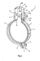
- a clamp 1 according to the invention is shown, which is arranged to be attached to a profile for suspending a pipe.
- the clamp 1 has a ring-shaped clamp body 2 comprising two clamp halves 3 and 4, respectively.
- the clamp body is preferably made from a steel strip or strip material from another type of metal.
- the clamp halves 3 and 4, respectively, are connected to each other through hinging means 5.
- the hinging means 5 comprise a flange 7 respectively 8 with a hole through which a screw 6 is running.
- the hinge construction shown here is only one of the many hinge constructions that are possible in a clamp according to the current invention.
- the clamp 1 also comprises a separately made suspension part 10 that is connected to the clamp body 2.
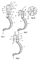
- Fig. 2 shows the suspension part 10 together with the clamp half 4 in an as yet uncoupled situation.
- the suspension part 10 is made as a mainly U-shaped clamp and in the example shown has two substantially parallel legs 11 and 12 and a connection piece 13 that connects the two legs 11, 12.
- the legs 11, 12 and the connection piece 13 are made out of one piece, preferably a steel strip or another type of metal. In practice, this strip can have a thickness of, for example, 3 mm.
- the material of the clamp body 2 is thinner than the material of the suspension part 10.
- a positioning protrusion 14 is provided at the free end of one of the legs 11 of the suspension part 10 .
- the leg 11 is furthermore provided with a hole 15 for inserting a screw 30 or the like.
- the flange 9 is provided with a hole 17 for inserting the abovementioned screw 30 or the like.
- a positioning recess 16 is made for receiving the positioning protrusion 14. During assembly, the leg is placed against the flange 9 and the positioning protrusion 14 is inserted in the positioning recess 16.
- the holes 15 or 17 in the leg 11 or the flange 9 are in line, so that a screw 30 or the like can be run through it.
- the hole 17 in the flange 9 is preferably provided with an internal thread in order to cooperate with an external thread on a screw 30 or the like.
- a lip 18 is made at each of the sides, which, in an unassembled situation (see Fig. 2 ), extends mainly perpendicular with respect to the surface of the flange 9.
- recesses 19 are made with a length that mainly corresponds with the lips 18, so that the lips 18, when they extend along the flange, can fall into the recesses, as a result of which the flange 9 and the leg 11 are fixed with respect to each other in the longitudinal direction of the leg.
- the lips 18 are bent around the edges of the leg, at the height of the recesses 19, as shown in Fig 3a by the arrows 20, so that the flange 9 and the leg 11 are fixed with respect to each other.
- the flange 9 and the bent part of the clamp half are provided with a raised edge 21, which contributes to the rigidity of the clamp half 4. It is also possible that reinforcement ribs or the like ilar are made in the clamp halves 3, 4.
- the other leg 12 of the suspension element 10 is provided at its end with a hook member 22. Furthermore, the leg 12 is provided with a hole 23 that is in line with the hole 15 in the other leg 11.
- the clamp half 3 has an end part formed as flange 24. In the flange 24 a hook opening 25 is arranged, through which the hook device 22 can be inserted in order to then hook behind the upper edge 25a of the hook opening 25.
- the flange 24 is furthermore provided with a hole 26 for inserting a screw 30 or the like.
- the suspension part 10 and the clamp half 4 are preferably pre-assembled, i.e. already attached to each other when supplied to the installer.
- the attachment can (partly) take place by means of a machine in the factory where the parts are manufactured.
- the clamp halves 3 and 4 can also be supplied to the installer pre-assembled, but can also be supplied separately so that the installer will have to attach the clamp halves to each other, in the shown example he will do this by coupling flanges 7 and 8 by inserting and tightening the screw 6.
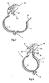
- the clamp 1 When the clamp half 4 is connected to the suspension part and the clamp halves 3 and 4 are connected to each other, the clamp 1 is ready for use. This situation is shown in Fig. 5 , wherein the clamp is open.
- the suspension part 10 can be attached over a profile 40 as illustrated in Fig. 6 and 7 .
- the bottom 43 can be provided with assembly holes that can be used to attach the profile 40 to a support part or support surface.
- Such a C-profile is an assembly means that is often used in the installation industry and it can be attached to a support surface such as a ceiling in a familiar way, for instance through threaded rods or other assembly means.
- Other profile forms are also possible of course without taking anything away from the soundness of the invention, e.g. profiles with a square, rectangular or round diameter.
- the suspension part 10 surrounds three sides of the profile 40, wherein the connection part 13 of the suspension element 10 will be adjacent to the bottom 43 of the profile and the legs 11, 12 of the suspension element 10 lie along the side walls 44 of the profile 40 as you can see in Fig. 7 .
- a pipe (not shown) can be inserted in the opened clamp body 2.
- the hinging means 5 are not directly under the centre line of the pipe, as a result of which the circle arch of the clamp half 4 attached to the suspension means 10 is longer than the circle arch of the other clamp half 3, the pipe - when being installed - will be laid in the clamp half 4, after which the clamp half 3 will be hinged close ( Fig. 7 ).
- the hook connection between the hook opening 25 and the hook member 22 is established, so that the clamp 1 is in a temporary assembly condition.
- the holes 15, 17, 23 and 26 are now in line, so that the screw 30 can be inserted.
- the screw 30 is screwed in the screw hole 17 in the flange 9 and tightened.
- the leg 12 of the suspension element 10 and the flange 24 of the clamp half 3 are fixed with respect to each other.
- the profile is locked between the legs 11, 12 and the connection piece 13 of the suspension part 10 and the screw 30.
- the legs 11, 12 of the suspension part 10 can be clamped against the side walls 44 of the profile 40, so that the clamp 1 is securely attached to the profile 40.
- connection piece 13 of the suspension part 10 is provided with a hole 13a for inserting a male attachment element such as a threaded rod or a bolt.
- a male attachment element such as a threaded rod or a bolt.
- the hole 13a could be provided with internal thread in order to work together with an external thread of a threaded end, bolt or the like.
- the hole 13a in the connection piece 13 of the suspension part 10 is continued, i.e. there is an edge 13b protruding from hole 13a in the direction of the clamp body.
- This edge can be used to position the suspension part 10 in the holes in the bottom of the profile.
- the edge 13b is fixed in longitudinal direction of the profile 40.
- the edge 13b is received while still movable in the longitudinal direction of the profile 40.
- the suspension part 10 if required, can be fixed to the profile 40 by clamping the legs 11, 12 of the suspension part 10 against the side walls 44 of the profile 40.
Landscapes
- Engineering & Computer Science (AREA)
- General Engineering & Computer Science (AREA)
- Mechanical Engineering (AREA)
- Clamps And Clips (AREA)
- Supports For Pipes And Cables (AREA)
Claims (12)
- Klemme (1) für ein Rohr oder dergleichen, die im Gebrauch an einem Profil (40) anzubringen ist, wobei die Klemme (1) einen hauptsächlich ringförmigen Klemmenkörper (2) zur Aufnahme des Rohrs und darüber hinaus ein Aufhängeteil (10) aufweist, das im Gebrauch das Profil zumindest teilweise umschließt, um den Klemmenkörper (2) am Profil (40) aufzuhängen, wobei der Klemmenkörper (2) und das Aufhängeteil (10) zwei separate Teile sind, die im Gebrauch miteinander verbunden sind, dadurch gekennzeichnet, dass das Aufhängeteil (10) Schenkel (11, 12) hat, die sich, wenn sie in Gebrauch sind, entlang der Seiten (44) des Profils (40) erstrecken, wobei der Klemmenkörper (2) ein Endteil (9) hat, das mit Anbringungseinrichtungen (16, 17, 18) versehen ist, die einen der Schenkel (11) des Aufhängeteils (10) fest am Klemmenkörper (2) anbringen werden, und wobei die Anbringungseinrichtungen eine oder mehrere Fixierungslippe/n (18) aufweisen, die um den Schenkel (11) des Aufhängeteils (10) herum gebogen werden kann bzw. können oder gebogen ist bzw. sind, um den Schenkel (11) des Aufhängeteils (10) am Endteil (9) des Klemmenkörpers (2) zu fixieren.
- Klemme nach Anspruch 1, wobei das Aufhängeteil (10) so angepasst ist, dass es zu dem Teil des Profils (40) komplementär ist, den es umschließt.
- Klemme nach Anspruch 1, wobei das Aufhängeteil aus einer hauptsächlich U-förmigen Klemme mit Schenkeln (11, 12) besteht, die durch ein Verbindungsstück (13) verbunden sind.
- Klemme nach Anspruch 1, wobei das Endteil (9) des Klemmenkörpers (2) an seinen Seiten mit Ausnehmungen versehen ist, mit denen die Fixierungslippen (18) in Eingriff gelangen.
- Klemme nach einem der vorhergehenden Ansprüche, wobei der Schenkel (11), der fest am Klemmenkörper (2) angebracht angeordnet ist, mit einem Positionierungsvorsprung (14) versehen ist, und wobei das Endteil (9) des Klemmenkörpers mit einer Öffnung (16) zur Aufnahme des Positionierungsvorsprungs (14) versehen ist.
- Klemme nach einem der vorhergehenden Ansprüche, wobei einer der Schenkel (12) des Aufhängeteils (10) und ein Endteil (24) des Klemmenkörpers (2) mit Hakeneinrichtungen (22, 26) versehen sind, um das Endteil (24) des Klemmenkörpers (2) am Schenkel (12) einzuhaken.
- Klemme nach einem der vorhergehenden Ansprüche, wobei in jedem der Schenkel (11, 12) des Aufhängeteils (10) gegenüberliegende Öffnungen (15, 23) angeordnet sind, um ein Fixierungselement (30) hindurchtreten zu lassen.
- Klemme nach einem der vorhergehenden Ansprüche, wobei in den Endteilen (9, 24) des Klemmenkörpers (2) gegenüberliegende Öffnungen (17, 26) angeordnet sind, um ein Fixierungselement (30) hindurchtreten zu lassen.
- Klemme nach den Ansprüchen 7 und 8, wobei die Öffnungen (15, 23) in den jeweiligen Schenkeln (11, 12) des Aufhängeteils (10) und die Öffnungen (17, 26) in den jeweiligen Endteilen (9, 24) des Klemmenkörpers (2) übereinstimmend angeordnet sind und ein Fixierungselement (30) durch die zuvor erwähnten Öffnungen (17, 26, 15, 23) hindurchtritt.
- Klemme nach einem der vorhergehenden Ansprüche, die eines oder mehrere der folgenden Merkmale aufweist:- der Klemmenkörper (2) hat zwei Klemmenhälften, die durch Anlenkeinrichtungen aneinander angelenkt sind;- das Aufhängeteil (10) besteht aus einem Metall-, vorzugsweise Stahlband;- der Klemmenkörper (2) besteht aus einem Metall-, vorzugsweise Stahlband;- der Klemmenkörper (2) und das Aufhängeteil (10) bestehen aus Metall-, vorzugsweise Stahlbändern mit unterschiedlichen Dicken;- das Aufhängeteil (10) und der Klemmenkörper (2) bestehen aus unterschiedlichen Materialien.
- Klemme nach Anspruch 3, wobei eine Öffnung (13a) im Verbindungsstück (13) des Aufhängeteils (10) vorgesehen ist, um ein Einsteckbefestigungselement hindurchtreten zu lassen, wobei das Verbindungsstück (13) des Aufhängeteils (10) vorzugsweise mit einem Umfangsrand (13b) versehen ist, der in Bezug auf die Seite des Verbindungsstücks (13) vorsteht, die dem Klemmenkörper zugewandt ist.
- Befestigungssystem zum Aufhängen eines Rohrs oder dergleichen, ein Profil (40) und eine Klemme (1) nach einem der vorhergehenden Ansprüche umfassend.
Priority Applications (1)
| Application Number | Priority Date | Filing Date | Title |
|---|---|---|---|
| PL08766708T PL2156083T3 (pl) | 2007-05-24 | 2008-05-26 | Zacisk do zawieszania rury |
Applications Claiming Priority (2)
| Application Number | Priority Date | Filing Date | Title |
|---|---|---|---|
| NL1033884A NL1033884C2 (nl) | 2007-05-24 | 2007-05-24 | Beugel voor het ophangen van een buis. |
| PCT/NL2008/000135 WO2008143501A1 (en) | 2007-05-24 | 2008-05-26 | Clamp for suspending a pipe |
Publications (2)
| Publication Number | Publication Date |
|---|---|
| EP2156083A1 EP2156083A1 (de) | 2010-02-24 |
| EP2156083B1 true EP2156083B1 (de) | 2015-07-08 |
Family
ID=38880986
Family Applications (1)
| Application Number | Title | Priority Date | Filing Date |
|---|---|---|---|
| EP08766708.5A Active EP2156083B1 (de) | 2007-05-24 | 2008-05-26 | Schelle für die aufhängung eines rohres |
Country Status (4)
| Country | Link |
|---|---|
| EP (1) | EP2156083B1 (de) |
| NL (1) | NL1033884C2 (de) |
| PL (1) | PL2156083T3 (de) |
| WO (1) | WO2008143501A1 (de) |
Cited By (1)
| Publication number | Priority date | Publication date | Assignee | Title |
|---|---|---|---|---|
| NL2016119B1 (en) * | 2016-01-19 | 2017-07-25 | Walraven Holding Bv J Van | Pipe hanger. |
Families Citing this family (3)
| Publication number | Priority date | Publication date | Assignee | Title |
|---|---|---|---|---|
| NL2002420C2 (en) | 2009-01-16 | 2010-07-19 | Flamco Bv | Improved pipe-suspension bracket. |
| FR2946409B1 (fr) * | 2009-06-09 | 2015-03-20 | Snecma | Support d'equipement en aeronautique. |
| JP5972826B2 (ja) * | 2013-04-30 | 2016-08-17 | 三喜工業株式会社 | 配管支持金具 |
Family Cites Families (4)
| Publication number | Priority date | Publication date | Assignee | Title |
|---|---|---|---|---|
| JP2844062B2 (ja) * | 1996-11-22 | 1999-01-06 | 日栄インテック株式会社 | 単一箇所締着用立バンド |
| JPH11230418A (ja) * | 1998-02-13 | 1999-08-27 | Nhk Spring Co Ltd | 配管支持装置 |
| DK1411286T3 (da) | 2002-10-16 | 2007-03-05 | Geberit Technik Ag | Rörbærer |
| KR200343996Y1 (ko) * | 2003-12-04 | 2004-03-11 | 김대식 | 배관용 파이프 행거 |
-
2007
- 2007-05-24 NL NL1033884A patent/NL1033884C2/nl not_active IP Right Cessation
-
2008
- 2008-05-26 PL PL08766708T patent/PL2156083T3/pl unknown
- 2008-05-26 WO PCT/NL2008/000135 patent/WO2008143501A1/en not_active Ceased
- 2008-05-26 EP EP08766708.5A patent/EP2156083B1/de active Active
Cited By (5)
| Publication number | Priority date | Publication date | Assignee | Title |
|---|---|---|---|---|
| NL2016119B1 (en) * | 2016-01-19 | 2017-07-25 | Walraven Holding Bv J Van | Pipe hanger. |
| WO2017126957A1 (en) * | 2016-01-19 | 2017-07-27 | J. Van Walraven Holding B.V. | Pipe hanger |
| CN108474501A (zh) * | 2016-01-19 | 2018-08-31 | J·范瓦尔拉芬私人控股有限公司 | 管吊架 |
| US10295086B2 (en) | 2016-01-19 | 2019-05-21 | J. Van Walraven Holding B.V. | Pipe hanger |
| CN108474501B (zh) * | 2016-01-19 | 2020-06-09 | J·范瓦尔拉芬私人控股有限公司 | 管吊架 |
Also Published As
| Publication number | Publication date |
|---|---|
| WO2008143501A1 (en) | 2008-11-27 |
| NL1033884C2 (nl) | 2008-11-25 |
| EP2156083A1 (de) | 2010-02-24 |
| PL2156083T3 (pl) | 2015-12-31 |
Similar Documents
| Publication | Publication Date | Title |
|---|---|---|
| US8882056B2 (en) | Top beam clamp | |
| US6273372B1 (en) | Sway brace fitting | |
| EP3256765B1 (de) | Rohrschelle | |
| KR20150129842A (ko) | 추가의 기능적 측면을 구비하는 채널 프레이밍 및 이것을 위한 피팅부 | |
| WO2010082818A1 (en) | Improved pipe-suspension bracket | |
| WO2008143501A1 (en) | Clamp for suspending a pipe | |
| JP5433119B2 (ja) | 配設体支持具 | |
| KR20110080434A (ko) | 배관용 파이프 행거 | |
| JP5096243B2 (ja) | 配設体の支持具 | |
| KR20090054179A (ko) | 사이드클램프 | |
| JP7325746B2 (ja) | 配管固定具用支持材 | |
| JP2010084498A (ja) | 排水竪管の支持構造 | |
| KR200417712Y1 (ko) | 파이프용 크램프가 결합된 케이블 행거 | |
| JP4446353B2 (ja) | 形鋼用吊ボルト支持金具 | |
| US7806375B1 (en) | Retaining key | |
| KR101370455B1 (ko) | 기능성 클램프 | |
| JP2001186621A (ja) | 子桁増設用金具 | |
| JP7813026B2 (ja) | ケーブル支持具 | |
| US20250354649A1 (en) | Clamp assembly using pins | |
| KR100886970B1 (ko) | 고정클램프 | |
| JP2017189055A (ja) | 分線金物留め具 | |
| JP2023050854A (ja) | 補強材及び雨樋固定構造 | |
| JP5308313B2 (ja) | 配設体支持具及び配設体支持具の設置構造 | |
| KR200452852Y1 (ko) | 배관지지용 행거 | |
| KR20100007401U (ko) | 행거용 찬넬 클램프 |
Legal Events
| Date | Code | Title | Description |
|---|---|---|---|
| PUAI | Public reference made under article 153(3) epc to a published international application that has entered the european phase |
Free format text: ORIGINAL CODE: 0009012 |
|
| 17P | Request for examination filed |
Effective date: 20091214 |
|
| AK | Designated contracting states |
Kind code of ref document: A1 Designated state(s): AT BE BG CH CY CZ DE DK EE ES FI FR GB GR HR HU IE IS IT LI LT LU LV MC MT NL NO PL PT RO SE SI SK TR |
|
| AX | Request for extension of the european patent |
Extension state: AL BA MK RS |
|
| DAX | Request for extension of the european patent (deleted) | ||
| 17Q | First examination report despatched |
Effective date: 20120906 |
|
| RIC1 | Information provided on ipc code assigned before grant |
Ipc: F16L 3/24 20060101ALI20150115BHEP Ipc: F16L 3/133 20060101AFI20150115BHEP Ipc: F16L 3/11 20060101ALI20150115BHEP |
|
| GRAP | Despatch of communication of intention to grant a patent |
Free format text: ORIGINAL CODE: EPIDOSNIGR1 |
|
| INTG | Intention to grant announced |
Effective date: 20150226 |
|
| GRAS | Grant fee paid |
Free format text: ORIGINAL CODE: EPIDOSNIGR3 |
|
| GRAA | (expected) grant |
Free format text: ORIGINAL CODE: 0009210 |
|
| AK | Designated contracting states |
Kind code of ref document: B1 Designated state(s): AT BE BG CH CY CZ DE DK EE ES FI FR GB GR HR HU IE IS IT LI LT LU LV MC MT NL NO PL PT RO SE SI SK TR |
|
| REG | Reference to a national code |
Ref country code: GB Ref legal event code: FG4D |
|
| REG | Reference to a national code |
Ref country code: AT Ref legal event code: REF Ref document number: 735678 Country of ref document: AT Kind code of ref document: T Effective date: 20150715 Ref country code: CH Ref legal event code: EP |
|
| REG | Reference to a national code |
Ref country code: IE Ref legal event code: FG4D |
|
| REG | Reference to a national code |
Ref country code: DE Ref legal event code: R096 Ref document number: 602008038934 Country of ref document: DE |
|
| REG | Reference to a national code |
Ref country code: NL Ref legal event code: T3 |
|
| REG | Reference to a national code |
Ref country code: AT Ref legal event code: MK05 Ref document number: 735678 Country of ref document: AT Kind code of ref document: T Effective date: 20150708 |
|
| REG | Reference to a national code |
Ref country code: LT Ref legal event code: MG4D |
|
| REG | Reference to a national code |
Ref country code: PL Ref legal event code: T3 |
|
| PG25 | Lapsed in a contracting state [announced via postgrant information from national office to epo] |
Ref country code: LV Free format text: LAPSE BECAUSE OF FAILURE TO SUBMIT A TRANSLATION OF THE DESCRIPTION OR TO PAY THE FEE WITHIN THE PRESCRIBED TIME-LIMIT Effective date: 20150708 Ref country code: FI Free format text: LAPSE BECAUSE OF FAILURE TO SUBMIT A TRANSLATION OF THE DESCRIPTION OR TO PAY THE FEE WITHIN THE PRESCRIBED TIME-LIMIT Effective date: 20150708 Ref country code: NO Free format text: LAPSE BECAUSE OF FAILURE TO SUBMIT A TRANSLATION OF THE DESCRIPTION OR TO PAY THE FEE WITHIN THE PRESCRIBED TIME-LIMIT Effective date: 20151008 Ref country code: LT Free format text: LAPSE BECAUSE OF FAILURE TO SUBMIT A TRANSLATION OF THE DESCRIPTION OR TO PAY THE FEE WITHIN THE PRESCRIBED TIME-LIMIT Effective date: 20150708 Ref country code: GR Free format text: LAPSE BECAUSE OF FAILURE TO SUBMIT A TRANSLATION OF THE DESCRIPTION OR TO PAY THE FEE WITHIN THE PRESCRIBED TIME-LIMIT Effective date: 20151009 |
|
| PG25 | Lapsed in a contracting state [announced via postgrant information from national office to epo] |
Ref country code: ES Free format text: LAPSE BECAUSE OF FAILURE TO SUBMIT A TRANSLATION OF THE DESCRIPTION OR TO PAY THE FEE WITHIN THE PRESCRIBED TIME-LIMIT Effective date: 20150708 Ref country code: SE Free format text: LAPSE BECAUSE OF FAILURE TO SUBMIT A TRANSLATION OF THE DESCRIPTION OR TO PAY THE FEE WITHIN THE PRESCRIBED TIME-LIMIT Effective date: 20150708 Ref country code: HR Free format text: LAPSE BECAUSE OF FAILURE TO SUBMIT A TRANSLATION OF THE DESCRIPTION OR TO PAY THE FEE WITHIN THE PRESCRIBED TIME-LIMIT Effective date: 20150708 Ref country code: PT Free format text: LAPSE BECAUSE OF FAILURE TO SUBMIT A TRANSLATION OF THE DESCRIPTION OR TO PAY THE FEE WITHIN THE PRESCRIBED TIME-LIMIT Effective date: 20151109 Ref country code: IS Free format text: LAPSE BECAUSE OF FAILURE TO SUBMIT A TRANSLATION OF THE DESCRIPTION OR TO PAY THE FEE WITHIN THE PRESCRIBED TIME-LIMIT Effective date: 20151108 Ref country code: AT Free format text: LAPSE BECAUSE OF FAILURE TO SUBMIT A TRANSLATION OF THE DESCRIPTION OR TO PAY THE FEE WITHIN THE PRESCRIBED TIME-LIMIT Effective date: 20150708 |
|
| REG | Reference to a national code |
Ref country code: DE Ref legal event code: R097 Ref document number: 602008038934 Country of ref document: DE |
|
| PG25 | Lapsed in a contracting state [announced via postgrant information from national office to epo] |
Ref country code: SK Free format text: LAPSE BECAUSE OF FAILURE TO SUBMIT A TRANSLATION OF THE DESCRIPTION OR TO PAY THE FEE WITHIN THE PRESCRIBED TIME-LIMIT Effective date: 20150708 Ref country code: IT Free format text: LAPSE BECAUSE OF FAILURE TO SUBMIT A TRANSLATION OF THE DESCRIPTION OR TO PAY THE FEE WITHIN THE PRESCRIBED TIME-LIMIT Effective date: 20150708 Ref country code: DK Free format text: LAPSE BECAUSE OF FAILURE TO SUBMIT A TRANSLATION OF THE DESCRIPTION OR TO PAY THE FEE WITHIN THE PRESCRIBED TIME-LIMIT Effective date: 20150708 Ref country code: CZ Free format text: LAPSE BECAUSE OF FAILURE TO SUBMIT A TRANSLATION OF THE DESCRIPTION OR TO PAY THE FEE WITHIN THE PRESCRIBED TIME-LIMIT Effective date: 20150708 Ref country code: EE Free format text: LAPSE BECAUSE OF FAILURE TO SUBMIT A TRANSLATION OF THE DESCRIPTION OR TO PAY THE FEE WITHIN THE PRESCRIBED TIME-LIMIT Effective date: 20150708 |
|
| PLBE | No opposition filed within time limit |
Free format text: ORIGINAL CODE: 0009261 |
|
| STAA | Information on the status of an ep patent application or granted ep patent |
Free format text: STATUS: NO OPPOSITION FILED WITHIN TIME LIMIT |
|
| PG25 | Lapsed in a contracting state [announced via postgrant information from national office to epo] |
Ref country code: RO Free format text: LAPSE BECAUSE OF FAILURE TO SUBMIT A TRANSLATION OF THE DESCRIPTION OR TO PAY THE FEE WITHIN THE PRESCRIBED TIME-LIMIT Effective date: 20150708 |
|
| 26N | No opposition filed |
Effective date: 20160411 |
|
| PG25 | Lapsed in a contracting state [announced via postgrant information from national office to epo] |
Ref country code: SI Free format text: LAPSE BECAUSE OF FAILURE TO SUBMIT A TRANSLATION OF THE DESCRIPTION OR TO PAY THE FEE WITHIN THE PRESCRIBED TIME-LIMIT Effective date: 20150708 |
|
| PG25 | Lapsed in a contracting state [announced via postgrant information from national office to epo] |
Ref country code: LU Free format text: LAPSE BECAUSE OF FAILURE TO SUBMIT A TRANSLATION OF THE DESCRIPTION OR TO PAY THE FEE WITHIN THE PRESCRIBED TIME-LIMIT Effective date: 20160526 |
|
| REG | Reference to a national code |
Ref country code: CH Ref legal event code: PL |
|
| GBPC | Gb: european patent ceased through non-payment of renewal fee |
Effective date: 20160526 |
|
| PG25 | Lapsed in a contracting state [announced via postgrant information from national office to epo] |
Ref country code: CH Free format text: LAPSE BECAUSE OF NON-PAYMENT OF DUE FEES Effective date: 20160531 Ref country code: LI Free format text: LAPSE BECAUSE OF NON-PAYMENT OF DUE FEES Effective date: 20160531 |
|
| REG | Reference to a national code |
Ref country code: IE Ref legal event code: MM4A |
|
| REG | Reference to a national code |
Ref country code: FR Ref legal event code: ST Effective date: 20170131 |
|
| PG25 | Lapsed in a contracting state [announced via postgrant information from national office to epo] |
Ref country code: FR Free format text: LAPSE BECAUSE OF NON-PAYMENT OF DUE FEES Effective date: 20160531 |
|
| PG25 | Lapsed in a contracting state [announced via postgrant information from national office to epo] |
Ref country code: IE Free format text: LAPSE BECAUSE OF NON-PAYMENT OF DUE FEES Effective date: 20160526 Ref country code: GB Free format text: LAPSE BECAUSE OF NON-PAYMENT OF DUE FEES Effective date: 20160526 |
|
| PG25 | Lapsed in a contracting state [announced via postgrant information from national office to epo] |
Ref country code: CY Free format text: LAPSE BECAUSE OF FAILURE TO SUBMIT A TRANSLATION OF THE DESCRIPTION OR TO PAY THE FEE WITHIN THE PRESCRIBED TIME-LIMIT Effective date: 20150708 Ref country code: HU Free format text: LAPSE BECAUSE OF FAILURE TO SUBMIT A TRANSLATION OF THE DESCRIPTION OR TO PAY THE FEE WITHIN THE PRESCRIBED TIME-LIMIT; INVALID AB INITIO Effective date: 20080526 |
|
| PG25 | Lapsed in a contracting state [announced via postgrant information from national office to epo] |
Ref country code: TR Free format text: LAPSE BECAUSE OF FAILURE TO SUBMIT A TRANSLATION OF THE DESCRIPTION OR TO PAY THE FEE WITHIN THE PRESCRIBED TIME-LIMIT Effective date: 20150708 Ref country code: MC Free format text: LAPSE BECAUSE OF FAILURE TO SUBMIT A TRANSLATION OF THE DESCRIPTION OR TO PAY THE FEE WITHIN THE PRESCRIBED TIME-LIMIT Effective date: 20150708 Ref country code: MT Free format text: LAPSE BECAUSE OF NON-PAYMENT OF DUE FEES Effective date: 20160531 |
|
| PG25 | Lapsed in a contracting state [announced via postgrant information from national office to epo] |
Ref country code: BG Free format text: LAPSE BECAUSE OF FAILURE TO SUBMIT A TRANSLATION OF THE DESCRIPTION OR TO PAY THE FEE WITHIN THE PRESCRIBED TIME-LIMIT Effective date: 20150708 |
|
| PGFP | Annual fee paid to national office [announced via postgrant information from national office to epo] |
Ref country code: NL Payment date: 20240524 Year of fee payment: 17 |
|
| PGFP | Annual fee paid to national office [announced via postgrant information from national office to epo] |
Ref country code: DE Payment date: 20240517 Year of fee payment: 17 |
|
| PGFP | Annual fee paid to national office [announced via postgrant information from national office to epo] |
Ref country code: BE Payment date: 20240524 Year of fee payment: 17 |
|
| PGFP | Annual fee paid to national office [announced via postgrant information from national office to epo] |
Ref country code: PL Payment date: 20250516 Year of fee payment: 18 |
|
| REG | Reference to a national code |
Ref country code: DE Ref legal event code: R119 Ref document number: 602008038934 Country of ref document: DE |
|
| REG | Reference to a national code |
Ref country code: NL Ref legal event code: MM Effective date: 20250601 |
|
| REG | Reference to a national code |
Ref country code: BE Ref legal event code: MM Effective date: 20250531 |
|
| PG25 | Lapsed in a contracting state [announced via postgrant information from national office to epo] |
Ref country code: NL Free format text: LAPSE BECAUSE OF NON-PAYMENT OF DUE FEES Effective date: 20250601 |
|
| PG25 | Lapsed in a contracting state [announced via postgrant information from national office to epo] |
Ref country code: DE Free format text: LAPSE BECAUSE OF NON-PAYMENT OF DUE FEES Effective date: 20251202 |
|
| PG25 | Lapsed in a contracting state [announced via postgrant information from national office to epo] |
Ref country code: BE Free format text: LAPSE BECAUSE OF NON-PAYMENT OF DUE FEES Effective date: 20250531 |