EP2156104B1 - Système de ventilation - Google Patents
Système de ventilation Download PDFInfo
- Publication number
- EP2156104B1 EP2156104B1 EP08766786.1A EP08766786A EP2156104B1 EP 2156104 B1 EP2156104 B1 EP 2156104B1 EP 08766786 A EP08766786 A EP 08766786A EP 2156104 B1 EP2156104 B1 EP 2156104B1
- Authority
- EP
- European Patent Office
- Prior art keywords
- air
- ceiling
- supply channel
- air supply
- room
- Prior art date
- Legal status (The legal status is an assumption and is not a legal conclusion. Google has not performed a legal analysis and makes no representation as to the accuracy of the status listed.)
- Not-in-force
Links
- 238000009423 ventilation Methods 0.000 title claims description 22
- 238000000034 method Methods 0.000 claims description 10
- 238000002955 isolation Methods 0.000 claims description 7
- 238000005265 energy consumption Methods 0.000 description 5
- 238000010276 construction Methods 0.000 description 4
- 238000010438 heat treatment Methods 0.000 description 4
- 230000006698 induction Effects 0.000 description 4
- 230000035515 penetration Effects 0.000 description 4
- 238000011835 investigation Methods 0.000 description 3
- 238000007664 blowing Methods 0.000 description 2
- 230000003247 decreasing effect Effects 0.000 description 2
- 230000002349 favourable effect Effects 0.000 description 2
- 238000004519 manufacturing process Methods 0.000 description 2
- 238000013021 overheating Methods 0.000 description 2
- 210000001747 pupil Anatomy 0.000 description 2
- 238000011084 recovery Methods 0.000 description 2
- 230000008439 repair process Effects 0.000 description 2
- 206010034568 Peripheral coldness Diseases 0.000 description 1
- 238000004378 air conditioning Methods 0.000 description 1
- 230000033228 biological regulation Effects 0.000 description 1
- 238000001816 cooling Methods 0.000 description 1
- 239000000203 mixture Substances 0.000 description 1
- 230000000149 penetrating effect Effects 0.000 description 1
- 230000000630 rising effect Effects 0.000 description 1
- 238000000926 separation method Methods 0.000 description 1
Images

Classifications
-
- F—MECHANICAL ENGINEERING; LIGHTING; HEATING; WEAPONS; BLASTING
- F24—HEATING; RANGES; VENTILATING
- F24F—AIR-CONDITIONING; AIR-HUMIDIFICATION; VENTILATION; USE OF AIR CURRENTS FOR SCREENING
- F24F7/00—Ventilation
- F24F7/04—Ventilation with ducting systems, e.g. by double walls; with natural circulation
- F24F7/06—Ventilation with ducting systems, e.g. by double walls; with natural circulation with forced air circulation, e.g. by fan positioning of a ventilator in or against a conduit
- F24F7/10—Ventilation with ducting systems, e.g. by double walls; with natural circulation with forced air circulation, e.g. by fan positioning of a ventilator in or against a conduit with air supply, or exhaust, through perforated wall, floor or ceiling
-
- E—FIXED CONSTRUCTIONS
- E04—BUILDING
- E04B—GENERAL BUILDING CONSTRUCTIONS; WALLS, e.g. PARTITIONS; ROOFS; FLOORS; CEILINGS; INSULATION OR OTHER PROTECTION OF BUILDINGS
- E04B9/00—Ceilings; Construction of ceilings, e.g. false ceilings; Ceiling construction with regard to insulation
- E04B9/02—Ceilings; Construction of ceilings, e.g. false ceilings; Ceiling construction with regard to insulation having means for ventilation or vapour discharge
-
- F—MECHANICAL ENGINEERING; LIGHTING; HEATING; WEAPONS; BLASTING
- F24—HEATING; RANGES; VENTILATING
- F24F—AIR-CONDITIONING; AIR-HUMIDIFICATION; VENTILATION; USE OF AIR CURRENTS FOR SCREENING
- F24F12/00—Use of energy recovery systems in air conditioning, ventilation or screening
- F24F12/001—Use of energy recovery systems in air conditioning, ventilation or screening with heat-exchange between supplied and exhausted air
- F24F12/006—Use of energy recovery systems in air conditioning, ventilation or screening with heat-exchange between supplied and exhausted air using an air-to-air heat exchanger
-
- F—MECHANICAL ENGINEERING; LIGHTING; HEATING; WEAPONS; BLASTING
- F24—HEATING; RANGES; VENTILATING
- F24F—AIR-CONDITIONING; AIR-HUMIDIFICATION; VENTILATION; USE OF AIR CURRENTS FOR SCREENING
- F24F11/00—Control or safety arrangements
- F24F11/0001—Control or safety arrangements for ventilation
- F24F2011/0002—Control or safety arrangements for ventilation for admittance of outside air
-
- Y—GENERAL TAGGING OF NEW TECHNOLOGICAL DEVELOPMENTS; GENERAL TAGGING OF CROSS-SECTIONAL TECHNOLOGIES SPANNING OVER SEVERAL SECTIONS OF THE IPC; TECHNICAL SUBJECTS COVERED BY FORMER USPC CROSS-REFERENCE ART COLLECTIONS [XRACs] AND DIGESTS
- Y02—TECHNOLOGIES OR APPLICATIONS FOR MITIGATION OR ADAPTATION AGAINST CLIMATE CHANGE
- Y02B—CLIMATE CHANGE MITIGATION TECHNOLOGIES RELATED TO BUILDINGS, e.g. HOUSING, HOUSE APPLIANCES OR RELATED END-USER APPLICATIONS
- Y02B30/00—Energy efficient heating, ventilation or air conditioning [HVAC]
- Y02B30/56—Heat recovery units
Definitions
- the invention refers to a ventilation system especially for classrooms and other dwelling, living and/or working spaces, hereinafter, for the sake of simplicity - however, not to be understood in any limiting sense - indicated as classrooms or rooms.
- Air conditioning of classrooms etc. is a difficult problem, because large amounts of outside air have to be let in into the classroom without causing draught.
- the CO 2 level which legally is allowed to be 1200 ppm, often is a multiple of this value during some parts of the day. Recent investigations have shown that this also influences the school results. At arithmetic, for instance, it appears that even at small exceedings of the CO 2 level of 1200 ppm, the results are rewarded with a report mark 6 while it would have been a 7.5 when the CO 2 level would have been about 800 ppm.
- the present invention aims to offer a solution for the problems indicated in the foregoing.
- the invention preferably provides a method for ventilating rooms, especially classrooms (1) and similar rooms, comprising:
- a further embodiment concerns a method for ventilating classrooms and similar rooms, comprising next steps:
- the whole ceiling surface is used to supply air to the classroom instead of blowing air concentratedly ("cold spots") via windows or grids in the façade or the ceiling.
- air concentratedly Via a pattern of air outlet openings in the (lowered) ceiling the air is blown into the room.
- the air blown in will be mixed with the room air and thus the possible temperature difference will be equalized before the air comes into the living zone (height of about ⁇ 1.80 m).
- the lowered ceiling is used as a distribution element having a maximum distribution surface which is incomparably much larger than the surface of the inflow opening(s) via which the outside air is let in (also much larger than when - according to the prior art - supplied via open windows or ceiling grids). Because the distribution surface is much larger, no draught will occur.
- the system has a relative low flow resistance, which is favourable for the energy consumption.
- For the air distribution use may be made of existing components, which often are already present in classrooms, thus reducing the costs.
- the inflow speed lies between 1 and 4 m/s, depending on the remaining parameters, e.g. 2 m/s.
- the means for forced air inlet from the outside air into the room above the lowered ceiling are formed by an electrical ventilator.
- the energy consumption for heating may be reduced by - optionally - providing a (more or less heat conducting) heat recovery (HR) plate between an air supply channel and an air exhaust channel, thus enabling the exhaust air to warm up the supply air.
- HR heat recovery
- isolation plate By means of a more or less isolating separation plate, indicated hereinafter as isolation plate, it can be achieved that the supply air can be blown via the underside of the (e.g. concrete) floor of the above storey (or the roof). A relatively high air speed will increase heat exchange with the concrete mass. By doing so it is possible to cool (during warm weather) this concrete floor at night. By day this cold can be used then to cool the supply air. In winter the isolation in this isolation plate, but certainly also the stationary air in the (small) room between the isolation plate and the ceiling, provides an isolating layer. By this it can be prevented that heat will be withdrawn from the ceiling, which possibly would lead to complaints (cold feet) at the higher floor.
- isolation plate By means of a more or less isolating separation plate, indicated hereinafter as isolation plate, it can be achieved that the supply air can be blown via the underside of the (e.g. concrete) floor of the above storey (or the roof). A relatively high air speed will increase heat exchange with the concrete mass
- the large surface is also advantageous for the standing time and pressure drop of a filter possibly provided. Due to this the energy consumption remains low and it is possible to achieve a long filter standing time. This offers the possibility to replace filters during "major repairs”.
- a distribution valve or slide By means of, e.g., a distribution valve or slide it can be adjusted whether the supply air will be transferred to the outlet room via the first or via the second channel.
- the method according to the invention has the advantage that the components which are required for the method have more or less the shape of a lowered ceiling, i.e. are shaped of plates and may be installed in classrooms already in use by means of parts which are often used for installing lowered ceilings etc., e.g. hanging staves or wires.
- the invention also provides for a ventilation system for ventilating rooms like classrooms (1) and the like, comprising a surface structure (3) mainly extending parallel to a wall, ceiling (4) or floor of that room (1), and means (5) for forced air inlet from the outside air (6) into the room (2) between said surface structure and said wall, ceiling (4) or floor, and air outlet openings (7) mainly evenly spaced over the whole surface of the surface structure (3), wherein the ratio between the pitch and the diameter of said outlet openings is between 6 and 20:1, preferably between 10 and 16:1, more preferably around 13:1.
- Figure 1 shows a classroom 1 provided with a ventilation system using the room 2 between a lowered ceiling 3 and a ceiling 4.
- a ventilator 5 provides forced air inflow from the outside air 6 into the room 2 above the lowered ceiling.
- the fresh outside air sucked inward is mainly distributed to the classroom over the whole surface of the lowered ceiling 3, via air outlet openings 7 which are made evenly spaced in the lowered ceiling 3, as a result of which the whole surface of the lowered ceiling 3 will be used to supply fresh air to the classroom 1.
- the arrows in the figure indicate that the air blown in via the openings 7 will be mixed up by induction with the air already present in the classroom 1, causing that the possible temperature difference between blown in air and the air already present in the classroom 1 will be equalized before the air enters the living zone (below the height of about 1.80 m).
- the air let in from the outside will additionally be warmed-up with heat originating from the classroom by the lowered ceiling, and from other construction parts like e.g. the roof, causing that the air given off by the outlet openings will be less cold than the air let in from the outside.
- the ventilation system may be used to cool down the construction above the lowered ceiling during the night. By doing so it is possible to blow in fresh air by day at a lower temperature than the outside temperature.
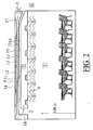
- heat may be recovered from the exhaust air, which option will be treated in the discussion of figure 2 .
- the pitch between the openings (7) is such that induction air, i.e. the room air rising towards the ceiling, will rise between the air blowing out of the openings (7), such that advantageous mixing may be achieved.
- the openings (7) preferably have such small surface areas and/or diameters that the travelling distance of the blown air is such that no or hardly any draft is felt by people in the room, or at least by most people in the room. For example, the travelling distance may be relatively short. Furthermore, it has been found that for optimal room ventilation that has above advantages, there may be a relation between the pitch between the openings (7) and the surface area of the openings (7).
- the ratio between said pitch and said surface area is between 6 and 20:1, preferably between 10 and 16:1, more preferably around 13:1. In this way, an advantage mixture of air in the room (1) and air from outside can be achieved so that draft, or a sense of draft, is prevented.
- the draft and/or the blown air will not be sensed at a relatively small distance from the ceiling (3), i.e. the penetration depth of the blown air will be relatively small. From investigation it has been found that at a penetration depth of thirty times the diameter of the opening (7) the speed of the blown air has decreased to 10% of the inflow speed.
- the openings (7) have a diameter of approximately 23 millimetres, wherein at a penetrating depth of the blown air of 700 millimetre from the opening (7), an original inflow speed of 2 meters per second can be decreased to approximately 0,2 meters per second. Smaller openings (7) could also be applied, wherein the penetration of the blown air has a smaller depth. For example, openings (7) having a diameter of 10 millimetres, and having a pitch of approximately 130 millimetres could be applied. In this case, the penetration depth could be approximately 300 millimetres.
- the diameter of the opening (7) is to be understood as the distance between two opposite points on the edge of the opening (7).
- the openings (7) may for example have a circular or square shaped cross section but could also have any other shape, for example slot-shaped.
- the invention could also comprise another surface structure that is parallel to the wall or floor of the room 1. In this case, the same advantages can be achieved.
- the room could in principle be any room.
- the main components shown in figures 1 and 2 have more or less the shape of plates and may be installed by means of constructions which are commonly used for lowered ceilings in new or existing classrooms, e.g. hanging staves or wires.
- Figure 2 shows how inside the room between the lowered ceiling 3 and the roof or the upper storey floor 4 an additional number of flat layers may be installed, e.g. by means of, like for the lowered ceiling 3, hanging wires or staves (not shown).
- first supply channel 11 there are visible a first supply channel 11, a plate 12, a second supply channel 13, a plate 14, an exhaust channel 15 and a plate 16.
- plates 14 and 16 heat may be exchanged and those may thus be indicated as HR plates.
- plate 12 has heat isolating properties.
- a valve or slide 17 can open and close the entries of the first and second supply channel.
- Exhaust channel 15 is connected with the classroom 1 via one or more connection channels 18. Those connection channels 18 are narrower than the plates 12, 14 and 16 (which is not visible well in the figure).
- the energy consumption for heating may be reduced by warming-up the supply air by the exhaust air, viz. by - different from figure 2 - setting the valve 17 so that the supply air is sent to the room 2 via channel 13. In that case heat exchange will occur via the plate 14 between the supply channel 13 and the exhaust channel 15. Because this plate 14 extends over the whole surface of the classroom, the heat exchanging surface is very large.
- valve 17 By sending the supply air via the upper supply channel - by setting the valve 17 in the position drawn in figure 2 - it will be achieved that the supply air is blown directly under the floor of the above storey or the roof 4. A relatively high air speed will increase the heat exchange with the concrete mass. By doing so it is possible to cool this concrete floor at night. By day this cold may be used to cool the supply air.
- the valve 17 also may be put into various intermediate positions, thus enabling that - the openings of both air supply channels 11 and 13 are freely accessible then - the outside air can be supplied to the room 1 to be ventilated via both air supply channels, the lowered ceiling 3 and the air outlet openings 7. In that way the extent of heat recovery can be adjusted.
- the valve 17 may set manually and/or by control means, e.g. an electronic processor and a servomotor (both not shown).
- the large surface is advantageous too for the standing time and the pressure drop of any filter 18 in channel 11 and any filter 19 in channel 13. Because of this the energy consumption will remain low and it will be possible to achieve long filter standing times. This offers the possibility to perform filter replacement during "major repairs". As can be seen, the filters 18 and 19 can extend - placed askew - over almost the whole surface of the relevant plates 12 and 14 respectively.
Landscapes
- Engineering & Computer Science (AREA)
- Chemical & Material Sciences (AREA)
- Combustion & Propulsion (AREA)
- Mechanical Engineering (AREA)
- General Engineering & Computer Science (AREA)
- Architecture (AREA)
- Physics & Mathematics (AREA)
- Electromagnetism (AREA)
- Civil Engineering (AREA)
- Structural Engineering (AREA)
- Building Environments (AREA)
- Ventilation (AREA)
Claims (13)
- Procédé pour ventiler des salles, en particulier des salles de classe (1) et des salles similaires, consistant à :- agencer une structure de surface parallèle à une paroi, un plafond ou un plancher d'une salle (3) ;- agencer une entrée d'air pulsé (5) depuis l'air extérieur (6) jusque dans la salle (2) entre la structure de surface (3) et la paroi, le plafond ou le plancher ;- agencer des ouvertures de sortie d'air (7), espacées de manière régulière sur toute la surface de la structure de surface, le procédé étant caractérisé en ce que le rapport entre le pas et le diamètre des ouvertures de sortie est situé entre 6 et 20:1.
- Procédé selon la revendication 1, dans lequel le rapport entre le pas et le diamètre des ouvertures de sortie est entre 10 et 16:1, de préférence d'environ 13:1.
- Procédé selon les revendications 1 ou 2 pour ventiler des salles de classe (1) et des salles similaires, consistant à :- agencer un plafond abaissé (3) ;- agencer une entrée d'air pulsé (5) depuis l'air extérieur (6) dans la salle (2) au-dessus du plafond abaissé ;- agencer des ouvertures de sortie d'air (7), principalement espacées de manière régulière sur toute la surface du plafond abaissé.
- Système de ventilation pour ventiler des salles telles que des salles de classe (1) et analogues, comprenant une structure de surface (3) s'étendant parallèlement à une paroi, un plafond (4) ou un plancher de cette salle (1), et des moyens (5) d'entrée d'air pulsé depuis l'air extérieur (6) dans la salle (2) entre la structure de surface et la paroi, le plafond (4) ou le plancher, et des ouvertures de sortie d'air (7) espacées de manière régulière sur toute la surface de la structure de surface (3), le système de ventilation étant caractérisé en ce que le rapport entre le pas et le diamètre des ouvertures de sortie est situé entre 6 et 20:1.
- Système de ventilation selon la revendication 4, dans lequel le rapport entre le pas et le diamètre des ouvertures de sortie est entre 10 et 16:1, de préférence d'environ 13:1.
- Système de ventilation selon les revendications 4 ou 5, dans lequel la structure de surface constitue un plafond abaissé (3) parallèle au plafond (4).
- Système de ventilation selon l'une quelconque des revendications 4 à 6, dans lequel le diamètre hydraulique des ouvertures de sortie est entre 0,1 et 6 cm.
- Système de ventilation selon l'une quelconque des revendications 4 à 7, dans lequel les moyens d'entrée d'air pulsé depuis l'air extérieur dans la salle entre la structure de surface et la paroi, le plafond (4) ou le plancher sont formés par un ventilateur électrique (5).
- Système de ventilation selon l'une quelconque des revendications 4 à 8, comprenant un premier canal d'alimentation d'air (11), formé par la salle entre, d'un côté, le plafond (4) et, de l'autre côté, d'une plaque d'isolation (12) s'étendant principalement parallèlement au plafond, lequel premier canal d'alimentation d'air (11) peut former une liaison entre les moyens (5) d'entrée d'air pulsé et les ouvertures de sortie d'air (7) du plafond abaissé.
- Système de ventilation selon l'une quelconque des revendications 4 à 9, comprenant un second canal d'alimentation d'air (13) formé par la salle entre, d'un côté, la plaque d'isolation (12) et, de l'autre côté, une plaque haute résilience HR (14) s'étendant principalement parallèlement au plafond, entre ce second canal d'alimentation d'air (13) et un canal de sortie d'air (16) s'étendant également principalement parallèlement au plafond, qui forme, par l'intermédiaire de moyens de liaison (18) reliés à la salle (1) à ventiler, une liaison entre la salle à ventiler et l'air extérieur, lequel second canal d'alimentation d'air (13) peut également former une liaison entre les moyens (5) d'entrée d'air pulsé et les ouvertures de sortie d'air (7) du plafond abaissé.
- Système de ventilation selon la revendication 10, comprenant des moyens (17) pour alimenter au choix, manuellement ou par des moyens de commande, de l'air extérieur par l'intermédiaire du premier canal d'alimentation d'air (11) et/ou du second canal d'alimentation d'air (13).
- Système de ventilation selon les revendications 10 ou 11, muni d'un filtre (18, 19) dans le premier et/ou le second canal d'alimentation d'air (11, 13).
- Système de ventilation selon la revendication 12, dans lequel le filtre (18, 19) s'étend sur une partie importante de la longueur du canal d'alimentation d'air concerné (11, 13) et soit, au niveau du côté entrée de ce canal d'alimentation d'air, est fixé sur le côté supérieur du canal d'alimentation d'air et, au niveau du côté sortie du canal d'alimentation d'air, est fixé sur le côté inférieur du canal d'alimentation d'air, soit, au niveau du côté entrée de ce canal d'alimentation d'air, est fixé sur le côté inférieur du canal d'alimentation d'air et, au niveau du côté sortie du canal d'alimentation d'air, est fixé sur le côté supérieur du canal d'alimentation d'air.
Priority Applications (1)
| Application Number | Priority Date | Filing Date | Title |
|---|---|---|---|
| EP08766786.1A EP2156104B1 (fr) | 2007-06-07 | 2008-06-09 | Système de ventilation |
Applications Claiming Priority (3)
| Application Number | Priority Date | Filing Date | Title |
|---|---|---|---|
| EP07109827A EP2017539A1 (fr) | 2007-06-07 | 2007-06-07 | Système de ventilation |
| EP08766786.1A EP2156104B1 (fr) | 2007-06-07 | 2008-06-09 | Système de ventilation |
| PCT/NL2008/050363 WO2009005344A2 (fr) | 2007-06-07 | 2008-06-09 | Système de ventilation |
Publications (2)
| Publication Number | Publication Date |
|---|---|
| EP2156104A2 EP2156104A2 (fr) | 2010-02-24 |
| EP2156104B1 true EP2156104B1 (fr) | 2015-10-07 |
Family
ID=38649919
Family Applications (2)
| Application Number | Title | Priority Date | Filing Date |
|---|---|---|---|
| EP07109827A Withdrawn EP2017539A1 (fr) | 2007-06-07 | 2007-06-07 | Système de ventilation |
| EP08766786.1A Not-in-force EP2156104B1 (fr) | 2007-06-07 | 2008-06-09 | Système de ventilation |
Family Applications Before (1)
| Application Number | Title | Priority Date | Filing Date |
|---|---|---|---|
| EP07109827A Withdrawn EP2017539A1 (fr) | 2007-06-07 | 2007-06-07 | Système de ventilation |
Country Status (3)
| Country | Link |
|---|---|
| US (1) | US20100167637A1 (fr) |
| EP (2) | EP2017539A1 (fr) |
| WO (1) | WO2009005344A2 (fr) |
Families Citing this family (10)
| Publication number | Priority date | Publication date | Assignee | Title |
|---|---|---|---|---|
| US8382565B2 (en) * | 2008-06-09 | 2013-02-26 | International Business Machines Corporation | System and method to redirect and/or reduce airflow using actuators |
| EP2365152A1 (fr) | 2010-03-05 | 2011-09-14 | Nederlandse Organisatie voor toegepast -natuurwetenschappelijk onderzoek TNO | Système de plafond doté d'un cadre et de panneaux et incluant un moyen pour la création d'écarts de ventilation |
| EP2378023A1 (fr) | 2010-04-14 | 2011-10-19 | Nederlandse Organisatie voor toegepast -natuurwetenschappelijk onderzoek TNO | Système de plafond doté d'un cadre et de panneaux et incluant un moyen pour la création de trouées de ventilation |
| RU2495333C2 (ru) * | 2011-12-21 | 2013-10-10 | Закрытое акционерное общество "БЮРО ТЕХНИКИ" | Отопительно-охладительное потолочное устройство |
| DE102014204432B4 (de) * | 2014-03-11 | 2025-10-09 | Dauphin Entwicklungs- U. Beteiligungs-Gmbh | Belüftungs-Anordnung sowie Raum-Modul |
| FI20140087A7 (fi) * | 2014-03-26 | 2015-09-27 | Janovent Oy | Huonetilakohtainen ilmanvaihtopalkki sekä ilmanvaihtopalkkijono |
| FR3034793A1 (fr) * | 2015-04-13 | 2016-10-14 | Jean Paul Lefaucheux | Plafond recuperateur d'energie |
| WO2020191501A1 (fr) * | 2019-03-27 | 2020-10-01 | Algernon Pharmaceuticals Inc. | Procédés et utilisations de bémithyle et de dérivés pour le traitement d'une maladie pulmonaire, d'une stéatose hépatique et de troubles rénaux |
| CA3180431A1 (fr) | 2020-05-29 | 2021-12-02 | Norbert Peter Vroege | Systeme de ventilation |
| NL2025707B1 (en) | 2020-05-29 | 2022-01-13 | Goflow Tech Ip B V | Ventilation system |
Family Cites Families (22)
| Publication number | Priority date | Publication date | Assignee | Title |
|---|---|---|---|---|
| GB489423A (en) * | 1935-12-17 | 1938-07-24 | Burgess Lab Inc C F | Improvements in ventilating system |
| US2221001A (en) * | 1936-10-27 | 1940-11-12 | Johns Manville | Ventilating ceiling |
| US2198867A (en) * | 1937-09-18 | 1940-04-30 | Gordon M Fair | Method of and apparatus for preventing infection |
| US2807993A (en) * | 1955-01-03 | 1957-10-01 | Airson Co Inc | Ventilating ceiling construction |
| US3058411A (en) * | 1959-12-30 | 1962-10-16 | Johns Manville | Ventilated ceiling constructions |
| US3099200A (en) * | 1960-07-14 | 1963-07-30 | Charles E Harrison | Air-distribution system |
| DE1253431B (de) * | 1960-11-30 | 1967-11-02 | Johann Aristides Raftopoulo Dr | Anlage zum Belueften und Klimatisieren von Gebaeuden, insbesondere Krankenhaeusern |
| US3255687A (en) * | 1963-07-25 | 1966-06-14 | Hauserman Co E F | Ventilating ceiling |
| US3303771A (en) * | 1965-02-11 | 1967-02-14 | Robert J Sigel Inc | Ventilated ceiling construction |
| US3403614A (en) * | 1967-04-28 | 1968-10-01 | Bendix Corp | Environmental enclosure with ceiling air plenum |
| FR2076813A5 (fr) * | 1970-01-29 | 1971-10-15 | Tunzini | |
| US3998142A (en) * | 1975-07-03 | 1976-12-21 | Sterilaire Medical, Inc. | Air circulating system for ultra clean areas |
| US4184538A (en) * | 1977-12-22 | 1980-01-22 | Rauenhorst George W | Ventilating heat exchanger for barns |
| DE3330536C2 (de) * | 1983-08-24 | 1985-08-22 | Fläkt AB, Nacka | Deckenkonstruktion für Reinräume |
| SE8803536L (sv) * | 1988-10-05 | 1990-04-06 | Givent Roger Ericsson Ab | Foerfarande foer vaermning och/eller kylning av till en byggnad inkommande luft |
| US5454756A (en) * | 1991-08-21 | 1995-10-03 | Pace Company | Clean room ventilation system |
| DE4201595C2 (de) * | 1992-01-22 | 1995-03-09 | Schmidt Reuter | Raumkühldecke |
| DE19730180C2 (de) * | 1997-07-15 | 2000-11-30 | Wilhelmi Werke Ag | Verfahren zur Raumklimatisierung und Klimadecke für ein solches Verfahren |
| SE513220C2 (sv) * | 1998-12-02 | 2000-07-31 | Johnson Medical Dev Pte Ltd | Sätt och anordning vid rumsventilation för s.k. renrum |
| DK174537B1 (da) * | 2000-11-17 | 2003-05-19 | L Hammerich & Co As | System og fremgangsmåde til klimakontrol i et rum, et loft til brug herved samt en fremgangsmåde til installation heraf |
| US6817941B1 (en) * | 2001-10-25 | 2004-11-16 | Lsi Logic Corporation | Uniform airflow diffuser |
| US6945866B2 (en) * | 2002-05-17 | 2005-09-20 | Airfixture L.L.C. | Method and apparatus for delivering conditioned air using pulse modulation |
-
2007
- 2007-06-07 EP EP07109827A patent/EP2017539A1/fr not_active Withdrawn
-
2008
- 2008-06-09 US US12/663,331 patent/US20100167637A1/en not_active Abandoned
- 2008-06-09 EP EP08766786.1A patent/EP2156104B1/fr not_active Not-in-force
- 2008-06-09 WO PCT/NL2008/050363 patent/WO2009005344A2/fr not_active Ceased
Also Published As
| Publication number | Publication date |
|---|---|
| US20100167637A1 (en) | 2010-07-01 |
| EP2156104A2 (fr) | 2010-02-24 |
| WO2009005344A3 (fr) | 2009-02-26 |
| WO2009005344A2 (fr) | 2009-01-08 |
| EP2017539A1 (fr) | 2009-01-21 |
Similar Documents
| Publication | Publication Date | Title |
|---|---|---|
| EP2156104B1 (fr) | Système de ventilation | |
| DE69031540T2 (de) | Vorrichtung zur Vorwärmung von Luft zur Gebäudelüftung | |
| DE3321612A1 (de) | Klimageraet | |
| JP5370880B2 (ja) | 省エネルギー建物 | |
| Almazmumi et al. | A novel wall windcatcher (WWC) natural ventilation system evaluated through CFD and experimental field testing-a solution to single-sided ventilation in multi-story buildings? | |
| CN101059279B (zh) | 空气式太阳能集热换气系统 | |
| US20210262679A1 (en) | Convection-enhanced central air conditioning system | |
| EP2378216A2 (fr) | Dispositif d'aération | |
| JP2008076015A (ja) | 地熱利用による建築物空調システム | |
| DE19736998C1 (de) | Anordnung zur Klimatisierung von Gebäuden | |
| Liddament et al. | Achieving natural and hybrid ventilation in practice | |
| WO2013087224A1 (fr) | Module multifonctionnel pour commande de l'amenée d'eau et de l'amenée d'air dans une dalle active de climatisation | |
| US7698903B1 (en) | Energy efficient ventilation system | |
| CN205558358U (zh) | 节能型轻钢活动房 | |
| EP0932799B1 (fr) | Immeuble avec un systeme de chauffage | |
| JP2015086566A (ja) | 通気採熱型融雪および滑雪方法 | |
| JPS5950033B2 (ja) | 冷暖房装置 | |
| DE2542234A1 (de) | Doppelbodensystem aus platten auf stuetzfuessen zur bildung einer installationszone | |
| CN223909684U (zh) | 一种空调水系统控制装置 | |
| HK1051398A1 (zh) | 在建築物外墻和建築物中導引外界空氣的方法及建築物控溫方法 | |
| DE102006053355B4 (de) | Heiz- und Belüftungsvorrichtung | |
| CN219177796U (zh) | 一种有吊顶的高大空间建筑用节能供暖系统 | |
| WO2008082370A2 (fr) | Panneau à activation thermique | |
| JP2846913B2 (ja) | ビルの空気予熱方法および装置 | |
| WO1990011476A1 (fr) | Methode et dispositif de regulation de la temperature dans les bâtiments |
Legal Events
| Date | Code | Title | Description |
|---|---|---|---|
| PUAI | Public reference made under article 153(3) epc to a published international application that has entered the european phase |
Free format text: ORIGINAL CODE: 0009012 |
|
| 17P | Request for examination filed |
Effective date: 20091210 |
|
| AK | Designated contracting states |
Kind code of ref document: A2 Designated state(s): AT BE BG CH CY CZ DE DK EE ES FI FR GB GR HR HU IE IS IT LI LT LU LV MC MT NL NO PL PT RO SE SI SK TR |
|
| AX | Request for extension of the european patent |
Extension state: AL BA MK RS |
|
| 111L | Licence recorded |
Designated state(s): AT BE BG CH CY CZ DE DK EE ES FI FR GB GR HR HU IE IS IT LT LU LV MC MT NL NO PL PT RO SE SI SK TR Free format text: EXCLUSIVE LICENSE Name of requester: DELFT PATENTS B.V., NL Effective date: 20100914 |
|
| DAX | Request for extension of the european patent (deleted) | ||
| RIC1 | Information provided on ipc code assigned before grant |
Ipc: F24F 12/00 20060101ALI20150128BHEP Ipc: F24F 7/00 20060101ALI20150128BHEP Ipc: F24F 7/10 20060101AFI20150128BHEP Ipc: E04B 9/02 20060101ALI20150128BHEP Ipc: F24F 11/00 20060101ALI20150128BHEP |
|
| GRAP | Despatch of communication of intention to grant a patent |
Free format text: ORIGINAL CODE: EPIDOSNIGR1 |
|
| INTG | Intention to grant announced |
Effective date: 20150324 |
|
| RAP1 | Party data changed (applicant data changed or rights of an application transferred) |
Owner name: NEDERLANDSE ORGANISATIE VOOR TOEGEPAST- NATUURWETE |
|
| GRAS | Grant fee paid |
Free format text: ORIGINAL CODE: EPIDOSNIGR3 |
|
| GRAA | (expected) grant |
Free format text: ORIGINAL CODE: 0009210 |
|
| 111L | Licence recorded |
Designated state(s): AT BE BG CH CY CZ DE DK EE ES FI FR GB GR HR HU IE IS IT LT LU LV MC MT NL NO PL PT RO SE SI SK TR Free format text: EXCLUSIVE LICENSE Name of requester: DELFT PATENTS B.V., NL Effective date: 20100914 |
|
| AK | Designated contracting states |
Kind code of ref document: B1 Designated state(s): AT BE BG CH CY CZ DE DK EE ES FI FR GB GR HR HU IE IS IT LI LT LU LV MC MT NL NO PL PT RO SE SI SK TR |
|
| REG | Reference to a national code |
Ref country code: GB Ref legal event code: FG4D |
|
| REG | Reference to a national code |
Ref country code: AT Ref legal event code: REF Ref document number: 753984 Country of ref document: AT Kind code of ref document: T Effective date: 20151015 Ref country code: CH Ref legal event code: EP Ref country code: CH Ref legal event code: PK Free format text: ERGAENZUNG LIZENZEINTRAG: AUSSCHLIESSLICHE LIZENZ |
|
| REG | Reference to a national code |
Ref country code: IE Ref legal event code: FG4D |
|
| REG | Reference to a national code |
Ref country code: DE Ref legal event code: R096 Ref document number: 602008040533 Country of ref document: DE |
|
| REG | Reference to a national code |
Ref country code: AT Ref legal event code: MK05 Ref document number: 753984 Country of ref document: AT Kind code of ref document: T Effective date: 20151007 |
|
| REG | Reference to a national code |
Ref country code: LT Ref legal event code: MG4D |
|
| REG | Reference to a national code |
Ref country code: NL Ref legal event code: FP |
|
| PG25 | Lapsed in a contracting state [announced via postgrant information from national office to epo] |
Ref country code: HR Free format text: LAPSE BECAUSE OF FAILURE TO SUBMIT A TRANSLATION OF THE DESCRIPTION OR TO PAY THE FEE WITHIN THE PRESCRIBED TIME-LIMIT Effective date: 20151007 Ref country code: IS Free format text: LAPSE BECAUSE OF FAILURE TO SUBMIT A TRANSLATION OF THE DESCRIPTION OR TO PAY THE FEE WITHIN THE PRESCRIBED TIME-LIMIT Effective date: 20160207 Ref country code: NO Free format text: LAPSE BECAUSE OF FAILURE TO SUBMIT A TRANSLATION OF THE DESCRIPTION OR TO PAY THE FEE WITHIN THE PRESCRIBED TIME-LIMIT Effective date: 20160107 Ref country code: IT Free format text: LAPSE BECAUSE OF FAILURE TO SUBMIT A TRANSLATION OF THE DESCRIPTION OR TO PAY THE FEE WITHIN THE PRESCRIBED TIME-LIMIT Effective date: 20151007 Ref country code: ES Free format text: LAPSE BECAUSE OF FAILURE TO SUBMIT A TRANSLATION OF THE DESCRIPTION OR TO PAY THE FEE WITHIN THE PRESCRIBED TIME-LIMIT Effective date: 20151007 Ref country code: LT Free format text: LAPSE BECAUSE OF FAILURE TO SUBMIT A TRANSLATION OF THE DESCRIPTION OR TO PAY THE FEE WITHIN THE PRESCRIBED TIME-LIMIT Effective date: 20151007 |
|
| PG25 | Lapsed in a contracting state [announced via postgrant information from national office to epo] |
Ref country code: AT Free format text: LAPSE BECAUSE OF FAILURE TO SUBMIT A TRANSLATION OF THE DESCRIPTION OR TO PAY THE FEE WITHIN THE PRESCRIBED TIME-LIMIT Effective date: 20151007 Ref country code: GR Free format text: LAPSE BECAUSE OF FAILURE TO SUBMIT A TRANSLATION OF THE DESCRIPTION OR TO PAY THE FEE WITHIN THE PRESCRIBED TIME-LIMIT Effective date: 20160108 Ref country code: PT Free format text: LAPSE BECAUSE OF FAILURE TO SUBMIT A TRANSLATION OF THE DESCRIPTION OR TO PAY THE FEE WITHIN THE PRESCRIBED TIME-LIMIT Effective date: 20160208 Ref country code: LV Free format text: LAPSE BECAUSE OF FAILURE TO SUBMIT A TRANSLATION OF THE DESCRIPTION OR TO PAY THE FEE WITHIN THE PRESCRIBED TIME-LIMIT Effective date: 20151007 Ref country code: FI Free format text: LAPSE BECAUSE OF FAILURE TO SUBMIT A TRANSLATION OF THE DESCRIPTION OR TO PAY THE FEE WITHIN THE PRESCRIBED TIME-LIMIT Effective date: 20151007 Ref country code: PL Free format text: LAPSE BECAUSE OF FAILURE TO SUBMIT A TRANSLATION OF THE DESCRIPTION OR TO PAY THE FEE WITHIN THE PRESCRIBED TIME-LIMIT Effective date: 20151007 Ref country code: SE Free format text: LAPSE BECAUSE OF FAILURE TO SUBMIT A TRANSLATION OF THE DESCRIPTION OR TO PAY THE FEE WITHIN THE PRESCRIBED TIME-LIMIT Effective date: 20151007 |
|
| REG | Reference to a national code |
Ref country code: DE Ref legal event code: R097 Ref document number: 602008040533 Country of ref document: DE |
|
| PG25 | Lapsed in a contracting state [announced via postgrant information from national office to epo] |
Ref country code: CZ Free format text: LAPSE BECAUSE OF FAILURE TO SUBMIT A TRANSLATION OF THE DESCRIPTION OR TO PAY THE FEE WITHIN THE PRESCRIBED TIME-LIMIT Effective date: 20151007 |
|
| PGFP | Annual fee paid to national office [announced via postgrant information from national office to epo] |
Ref country code: LU Payment date: 20160622 Year of fee payment: 9 |
|
| PLBE | No opposition filed within time limit |
Free format text: ORIGINAL CODE: 0009261 |
|
| STAA | Information on the status of an ep patent application or granted ep patent |
Free format text: STATUS: NO OPPOSITION FILED WITHIN TIME LIMIT |
|
| PG25 | Lapsed in a contracting state [announced via postgrant information from national office to epo] |
Ref country code: RO Free format text: LAPSE BECAUSE OF FAILURE TO SUBMIT A TRANSLATION OF THE DESCRIPTION OR TO PAY THE FEE WITHIN THE PRESCRIBED TIME-LIMIT Effective date: 20151007 Ref country code: DK Free format text: LAPSE BECAUSE OF FAILURE TO SUBMIT A TRANSLATION OF THE DESCRIPTION OR TO PAY THE FEE WITHIN THE PRESCRIBED TIME-LIMIT Effective date: 20151007 Ref country code: SK Free format text: LAPSE BECAUSE OF FAILURE TO SUBMIT A TRANSLATION OF THE DESCRIPTION OR TO PAY THE FEE WITHIN THE PRESCRIBED TIME-LIMIT Effective date: 20151007 Ref country code: EE Free format text: LAPSE BECAUSE OF FAILURE TO SUBMIT A TRANSLATION OF THE DESCRIPTION OR TO PAY THE FEE WITHIN THE PRESCRIBED TIME-LIMIT Effective date: 20151007 |
|
| PGFP | Annual fee paid to national office [announced via postgrant information from national office to epo] |
Ref country code: BE Payment date: 20160620 Year of fee payment: 9 |
|
| 26N | No opposition filed |
Effective date: 20160708 |
|
| PG25 | Lapsed in a contracting state [announced via postgrant information from national office to epo] |
Ref country code: SI Free format text: LAPSE BECAUSE OF FAILURE TO SUBMIT A TRANSLATION OF THE DESCRIPTION OR TO PAY THE FEE WITHIN THE PRESCRIBED TIME-LIMIT Effective date: 20151007 |
|
| REG | Reference to a national code |
Ref country code: DE Ref legal event code: R119 Ref document number: 602008040533 Country of ref document: DE |
|
| PG25 | Lapsed in a contracting state [announced via postgrant information from national office to epo] |
Ref country code: MC Free format text: LAPSE BECAUSE OF FAILURE TO SUBMIT A TRANSLATION OF THE DESCRIPTION OR TO PAY THE FEE WITHIN THE PRESCRIBED TIME-LIMIT Effective date: 20151007 |
|
| REG | Reference to a national code |
Ref country code: CH Ref legal event code: PL |
|
| GBPC | Gb: european patent ceased through non-payment of renewal fee |
Effective date: 20160609 |
|
| REG | Reference to a national code |
Ref country code: IE Ref legal event code: MM4A |
|
| REG | Reference to a national code |
Ref country code: FR Ref legal event code: ST Effective date: 20170228 |
|
| PG25 | Lapsed in a contracting state [announced via postgrant information from national office to epo] |
Ref country code: FR Free format text: LAPSE BECAUSE OF NON-PAYMENT OF DUE FEES Effective date: 20160630 Ref country code: DE Free format text: LAPSE BECAUSE OF NON-PAYMENT OF DUE FEES Effective date: 20170103 Ref country code: CH Free format text: LAPSE BECAUSE OF NON-PAYMENT OF DUE FEES Effective date: 20160630 Ref country code: LI Free format text: LAPSE BECAUSE OF NON-PAYMENT OF DUE FEES Effective date: 20160630 |
|
| PG25 | Lapsed in a contracting state [announced via postgrant information from national office to epo] |
Ref country code: IE Free format text: LAPSE BECAUSE OF NON-PAYMENT OF DUE FEES Effective date: 20160609 Ref country code: GB Free format text: LAPSE BECAUSE OF NON-PAYMENT OF DUE FEES Effective date: 20160609 |
|
| PG25 | Lapsed in a contracting state [announced via postgrant information from national office to epo] |
Ref country code: LU Free format text: LAPSE BECAUSE OF NON-PAYMENT OF DUE FEES Effective date: 20170609 |
|
| PG25 | Lapsed in a contracting state [announced via postgrant information from national office to epo] |
Ref country code: HU Free format text: LAPSE BECAUSE OF FAILURE TO SUBMIT A TRANSLATION OF THE DESCRIPTION OR TO PAY THE FEE WITHIN THE PRESCRIBED TIME-LIMIT; INVALID AB INITIO Effective date: 20080609 Ref country code: CY Free format text: LAPSE BECAUSE OF FAILURE TO SUBMIT A TRANSLATION OF THE DESCRIPTION OR TO PAY THE FEE WITHIN THE PRESCRIBED TIME-LIMIT Effective date: 20151007 |
|
| REG | Reference to a national code |
Ref country code: BE Ref legal event code: FP Effective date: 20151228 Ref country code: BE Ref legal event code: MM Effective date: 20170630 |
|
| PG25 | Lapsed in a contracting state [announced via postgrant information from national office to epo] |
Ref country code: TR Free format text: LAPSE BECAUSE OF FAILURE TO SUBMIT A TRANSLATION OF THE DESCRIPTION OR TO PAY THE FEE WITHIN THE PRESCRIBED TIME-LIMIT Effective date: 20151007 Ref country code: MT Free format text: LAPSE BECAUSE OF NON-PAYMENT OF DUE FEES Effective date: 20160630 |
|
| PG25 | Lapsed in a contracting state [announced via postgrant information from national office to epo] |
Ref country code: BG Free format text: LAPSE BECAUSE OF FAILURE TO SUBMIT A TRANSLATION OF THE DESCRIPTION OR TO PAY THE FEE WITHIN THE PRESCRIBED TIME-LIMIT Effective date: 20151007 |
|
| PGFP | Annual fee paid to national office [announced via postgrant information from national office to epo] |
Ref country code: NL Payment date: 20180620 Year of fee payment: 11 |
|
| PG25 | Lapsed in a contracting state [announced via postgrant information from national office to epo] |
Ref country code: BE Free format text: LAPSE BECAUSE OF NON-PAYMENT OF DUE FEES Effective date: 20170630 |
|
| REG | Reference to a national code |
Ref country code: NL Ref legal event code: MM Effective date: 20190701 |
|
| PG25 | Lapsed in a contracting state [announced via postgrant information from national office to epo] |
Ref country code: NL Free format text: LAPSE BECAUSE OF NON-PAYMENT OF DUE FEES Effective date: 20190701 |