EP2156203B1 - Verfahren und einrichtung zur vorhersage eines zustands eines stromversorgungssystems im zeitbereich - Google Patents
Verfahren und einrichtung zur vorhersage eines zustands eines stromversorgungssystems im zeitbereich Download PDFInfo
- Publication number
- EP2156203B1 EP2156203B1 EP07730024A EP07730024A EP2156203B1 EP 2156203 B1 EP2156203 B1 EP 2156203B1 EP 07730024 A EP07730024 A EP 07730024A EP 07730024 A EP07730024 A EP 07730024A EP 2156203 B1 EP2156203 B1 EP 2156203B1
- Authority
- EP
- European Patent Office
- Prior art keywords
- power system
- frequencies
- time
- state
- power
- Prior art date
- Legal status (The legal status is an assumption and is not a legal conclusion. Google has not performed a legal analysis and makes no representation as to the accuracy of the status listed.)
- Active
Links
Images


Classifications
-
- G—PHYSICS
- G01—MEASURING; TESTING
- G01R—MEASURING ELECTRIC VARIABLES; MEASURING MAGNETIC VARIABLES
- G01R31/00—Arrangements for testing electric properties; Arrangements for locating electric faults; Arrangements for electrical testing characterised by what is being tested not provided for elsewhere
- G01R31/08—Locating faults in cables, transmission lines, or networks
- G01R31/088—Aspects of digital computing
-
- H—ELECTRICITY
- H02—GENERATION; CONVERSION OR DISTRIBUTION OF ELECTRIC POWER
- H02J—ELECTRIC POWER NETWORKS; CIRCUIT ARRANGEMENTS OR SYSTEMS FOR SUPPLYING OR DISTRIBUTING ELECTRIC POWER; SYSTEMS FOR STORING ELECTRIC ENERGY
- H02J13/00—Circuit arrangements for providing remote monitoring or remote control of equipment in a power distribution network
- H02J13/14—Circuit arrangements for providing remote monitoring or remote control of equipment in a power distribution network the power network being locally controlled, e.g. home energy management systems [HEMS]
-
- H—ELECTRICITY
- H02—GENERATION; CONVERSION OR DISTRIBUTION OF ELECTRIC POWER
- H02J—ELECTRIC POWER NETWORKS; CIRCUIT ARRANGEMENTS OR SYSTEMS FOR SUPPLYING OR DISTRIBUTING ELECTRIC POWER; SYSTEMS FOR STORING ELECTRIC ENERGY
- H02J13/00—Circuit arrangements for providing remote monitoring or remote control of equipment in a power distribution network
- H02J13/18—Circuit arrangements for providing remote monitoring or remote control of equipment in a power distribution network characterised by the remotely-controlled equipment, e.g. converters or transformers
- H02J13/34—Circuit arrangements for providing remote monitoring or remote control of equipment in a power distribution network characterised by the remotely-controlled equipment, e.g. converters or transformers the equipment being switches, relays or circuit breakers
- H02J13/36—Circuit arrangements for providing remote monitoring or remote control of equipment in a power distribution network characterised by the remotely-controlled equipment, e.g. converters or transformers the equipment being switches, relays or circuit breakers specially adapted for protection systems
-
- G—PHYSICS
- G01—MEASURING; TESTING
- G01R—MEASURING ELECTRIC VARIABLES; MEASURING MAGNETIC VARIABLES
- G01R19/00—Arrangements for measuring currents or voltages or for indicating presence or sign thereof
- G01R19/25—Arrangements for measuring currents or voltages or for indicating presence or sign thereof using digital measurement techniques
- G01R19/2513—Arrangements for monitoring electric power systems, e.g. power lines or loads; Logging
-
- H—ELECTRICITY
- H02—GENERATION; CONVERSION OR DISTRIBUTION OF ELECTRIC POWER
- H02J—ELECTRIC POWER NETWORKS; CIRCUIT ARRANGEMENTS OR SYSTEMS FOR SUPPLYING OR DISTRIBUTING ELECTRIC POWER; SYSTEMS FOR STORING ELECTRIC ENERGY
- H02J13/00—Circuit arrangements for providing remote monitoring or remote control of equipment in a power distribution network
- H02J13/12—Monitoring network conditions, e.g. electrical magnitudes or operational status
-
- Y—GENERAL TAGGING OF NEW TECHNOLOGICAL DEVELOPMENTS; GENERAL TAGGING OF CROSS-SECTIONAL TECHNOLOGIES SPANNING OVER SEVERAL SECTIONS OF THE IPC; TECHNICAL SUBJECTS COVERED BY FORMER USPC CROSS-REFERENCE ART COLLECTIONS [XRACs] AND DIGESTS
- Y02—TECHNOLOGIES OR APPLICATIONS FOR MITIGATION OR ADAPTATION AGAINST CLIMATE CHANGE
- Y02E—REDUCTION OF GREENHOUSE GAS [GHG] EMISSIONS, RELATED TO ENERGY GENERATION, TRANSMISSION OR DISTRIBUTION
- Y02E60/00—Enabling technologies; Technologies with a potential or indirect contribution to GHG emissions mitigation
-
- Y—GENERAL TAGGING OF NEW TECHNOLOGICAL DEVELOPMENTS; GENERAL TAGGING OF CROSS-SECTIONAL TECHNOLOGIES SPANNING OVER SEVERAL SECTIONS OF THE IPC; TECHNICAL SUBJECTS COVERED BY FORMER USPC CROSS-REFERENCE ART COLLECTIONS [XRACs] AND DIGESTS
- Y04—INFORMATION OR COMMUNICATION TECHNOLOGIES HAVING AN IMPACT ON OTHER TECHNOLOGY AREAS
- Y04S—SYSTEMS INTEGRATING TECHNOLOGIES RELATED TO POWER NETWORK OPERATION, COMMUNICATION OR INFORMATION TECHNOLOGIES FOR IMPROVING THE ELECTRICAL POWER GENERATION, TRANSMISSION, DISTRIBUTION, MANAGEMENT OR USAGE, i.e. SMART GRIDS
- Y04S10/00—Systems supporting electrical power generation, transmission or distribution
- Y04S10/30—State monitoring, e.g. fault, temperature monitoring, insulator monitoring, corona discharge
Definitions
- the invention relates to a method and a device to predict a state of a power system by performing a Fast Fourier Transform on samples of a periodic waveform signal in order to determine a frequency spectrum of the periodic waveform signal, where the periodic waveform signal was derived from at least one measurable electric quantity of the power system and is representative for the state of the power system.
- the Fast Fourier Transform is performed by at least one processing unit which receives the samples of the periodic waveform signal from at least one storage unit.
- the term power system comprises power generation as well as power transmission and distribution systems and their power related components, such as power generators, power transformers, breakers, transmission and distribution lines etc.
- power generators power generators
- power transformers power transformers
- breakers transmission and distribution lines etc.
- the monitoring is usually based on measurements of electric quantities of the power system. As a result, to monitor means nowadays to detect events only after they have occurred.
- US 6,597,999 B1 disclose a method for predicting zero crossings of fault currents, using Fourier transforms.
- US 5,966,675 A discloses the use of frequency domain values for fault monitoring.
- the frequency spectrum of the periodic waveform signal is used to determine frequencies and related complex amplitudes at selected peaks in the frequency spectrum.
- the frequencies and corresponding complex amplitudes are stored together with a time stamp.
- a list of several frequencies and corresponding complex amplitudes is derivable.
- the list of frequencies and complex amplitudes is used in the next step to determine a predicted value of the periodic waveform signal in the time domain. Therefore a prediction time is chosen and a sum of sinusoidal signals is calculated at the prediction time, where each of the sinusoidal signals is characterized by one of the determined frequencies and its related complex amplitude as well as the time stamp.
- the frequencies and related complex amplitudes are determined from those peaks in the frequency spectrum whose amplitude exceeds a predetermined amplitude limit. Additionally or alternatively, the frequencies and related complex amplitudes may be determined after the frequency spectrum was filtered with a frequency filter.
- control actions usually require that the information the control decision is based upon is determined reliably and with shortest possible delay time, it is suggest in an embodiment to carry out the method on a computing device with a real-time operating system and to perform the step of determining the predicted value simultaneously with the steps of performing a Fast Fourier Transform and of determining the frequencies and related complex amplitudes.
- the periodic waveform signal reaches a certain predetermined amplitude or phase angle
- a control action can then be initiated in the power system at the best suitable point in time, when for example negative side effects of the control action are at a minimum or when the impact of the control action is at a maximum.
- the control action can be initiated either when the real time reaches precisely the predetermined point in time or it can be initiated at a certain time before the predetermined point in time, where the certain time is chosen in dependence on an expected delay in the reaction of the power system to the control action.
- the prediction of amplitude or phase angle of the periodic waveform signal can for example be applied to the switching of a power breaker.
- a breaker should ideally be switched at zero current through the breaker, so that no current is interrupted during the switching operation which would lead to increased wear of the breaker contacts. Accordingly, it is advantageous to predict the zero current crossing of the breaker current by determining the point in time when the breaker current is supposed to reach zero Ampere and to initiate the switching of the breaker to occur at exactly the zero current crossing in order to reduce the breaker wear.
- the method to predict a value of a periodic waveform signal in the time domain is used to detect a fault in the power system. Therefore the predicted value is compared with a measured value derived from a measurement of the at least one electric quantity of the power system, where the prediction time equals the point in time when the measurement is taken. Since it is often hardly possible to measure at a precisely given point in time, it is regarded as an inferior solution to first predict a value and then to try to measure at exactly the prediction time.
- a better way is first to determine the list of frequencies and related complex amplitudes from the frequency spectrum, second to measure the at least one electric quantity, third to determine the point in time when the measurement actually was taken, fourth to predict the value at a prediction time which equals the measuring instant and fifth to compare the measured and the predicted value. If a difference between the predicted value and the measured value exceeds a predetermined limit, an unexpected change in the state of the power system is notified in order to initiate further actions.
- the further actions can be different depending on the kind of the electric quantity and on the features of the power system. In the simplest case, a faulty state of the power system can be notified right away if the difference between the predicted value and the measured value exceeds the predetermined limit.
- Such analysis can include searching for specific patterns in the time development of the at least one electric quantity, which requires further measurements, which can be measurements derived before or after the prediction time.
- the further analysis may be performed either on-line on the same or a connected processing unit or off-line. Since the prediction method provides not only an indication of an unexpected change of the state of the power system but also an exact point in time when the state changed, all necessary data from before and after the event can be stored in order to be used for the further analysis. This enables the development and use of advanced algorithms for fault and state detection in the power system.
- the method according to this embodiment can be performed on-line, where the at least one electric quantity of the power system is measured constantly and compared to predicted values as fast as the measurements are performed.
- the measured values are stored and are used to continuously derive an updated frequency spectrum and an updated set of frequencies and related complex amplitudes from the frequency spectrum.
- the notification of the unexpected change in state may be done in various ways known in the art such as outputting an acoustic, visual or haptic information to an operator or to generate a message and to display and store the message.
- the initiation of further actions can then be performed either automatically or manually by the operator.
- the state of the power system which is to be predicted can be for example the absence of short-circuits, the availability of a power transmission line in a power grid or the quality of operation of a tap changer of a power transformer.
- An unexpected change in state would in these examples be an indication for that a short-circuit is detected or that the power transmission line is lost or that the tap changer does not function properly.
- a change in the periodic waveform signal is intentionally provoked and the change is recorded by storing a consecutive sequence of predicted values at consecutive prediction times.
- the change in the periodic waveform signal can for example be provoked by stepwise changing a reference signal for a control unit in the power system, the control unit being for example connected to a converter or filter unit in the power system.
- Another example for a provoked change is the stepping of a tap changer of a power transformer.
- the recorded sequence of predicted values is compared with an expected sequence of the periodic waveform signal and the result of the comparison is used to evaluate the state of the power system.
- the at least one processing unit is arranged to determine frequencies and related complex amplitudes at selected peaks in the frequency spectrum, to store the frequencies and amplitudes together with a time stamp in the storage unit, to determine a predicted value of the periodic waveform signal in the time domain at a prediction time by calculating a sum of sinusoidal signals at the prediction time, each of the sinusoidal signals being characterized by one of the determined frequencies and its related complex amplitude as well as the time stamp, and to store the predicted value in the storage unit.
- the storage unit can be either a contemporary storage unit such as a RAM from where data can be transmitted to a permanent storage unit afterwards or the storage unit can be a permanent storage unit such as ROM, hard disk, memory or flash memory card etc.
- the processing unit can be any unit able to receive, process and output digital information, such as a CPU, a microcontroller, a digital signal processor, an ASIC, a FPGA or a higher level processing device like an embedded computer.
- the processing unit is a digital processing unit running under a real-time operating system, where the processing unit determines the predicted value in a thread with high priority and performs the Fast Fourier Transform and determines the frequencies and related complex amplitudes in a thread with low priority.
- the device can for example be part of a protective relay or of a monitoring system distributed in a wide area.
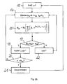
- Figure 1 shows a flowchart of a method to predict a future point in time when a current i through a breaker crosses zero.
- step 1 the samples of a periodic waveform signal ⁇ are recorded at consecutive points in time t, beginning at time to, where the periodic waveform signal ⁇ is equal to the current i through the breaker.
- step 2 a FFT is performed on the samples of the periodic waveform signal ⁇ in order to generate a frequency spectrum S( ⁇ ).
- An example for a frequency spectrum is shown in Figure 6 . From the frequency spectrum S( ⁇ ) certain peaks are selected by comparing the amplitudes A(S) in the spectrum with a predetermined amplitude limit A lim .
- Those peaks whose amplitude A(S) exceeds the predetermined amplitude limit A lim are selected and stored with the timestamp to (step 3), where the timestamp to indicates the point in time when the measurement samples to determine the frequencies f i and the corresponding complex amplitudes A i were recorded.
- the timestamp to indicates the point in time when the measurement samples to determine the frequencies f i and the corresponding complex amplitudes A i were recorded.
- five frequencies f i and their related complex amplitudes A i are determined.
- a loop is run to determine predicted values ⁇ pj of the periodic waveform signal in the time domain at consecutive prediction times t pj by calculating a sum of sinusoidal signals at the corresponding prediction time t pj , where each of the sinusoidal signals is characterized by one of the determined frequencies f i and its related complex amplitude A i as well as the time stamp to.
- For each of the predicted values ⁇ pj it is checked in step 6 if the value is closest to zero, i.e. if the predicted value ⁇ pj indicates the zero crossing of the current i. If a predicted value ⁇ pj is not equal or closest to zero, the next predicted value ⁇ p(j+1) is calculated.
- the switching time t s when the breaker is to be switched is calculated as difference between the zero crossing time t pa and a predetermined delay time t delay , which corresponds to the reaction time of the breaker to a switching signal (step 8).
- the real point in time t now is compared with the switching time t s , and when the switching time t s is reached a switching signal is sent to the breaker in step 10.
- Figure 2a shows the first routine of a method where two routines run in parallel.
- the first routine samples a periodic waveform signal ⁇ and processes the samples in order to provide continuously updated sets of frequencies f i and related complex amplitudes A i .
- the second routine uses the respective latest set to determine predicted values and to compare them with newly measured values of the periodic waveform signal.
- Steps 11 to 13 of Figure 2a are the same as steps 1 to 3 of Figure 1 , with the only difference that any periodic waveform signal ⁇ derived from at least one measurable electric quantity of a power system can be subject of the method.
- the number of samples to be taken in step 11 is predefined as X.
- step 14 it is checked if meanwhile enough new samples of the periodic waveform signal ⁇ were taken to reach the predetermined number X again. If not, it is waited until the predetermined number X is reached. When enough new samples are taken, the method returns to step 12 in order to perform an FFT on the new samples and to generate an updated set of frequencies f i and amplitudes A i from the resulting frequency spectrum S( ⁇ ). The updated frequencies f i and amplitudes A i are then stored together with their updated timestamp to, so that the former set of data is overwritten.
- a second routine is run which is depicted in Figure 2b .
- a counter k is set to zero and an index j is set to one.
- a new sample ⁇ mj of the periodic waveform signal ⁇ is taken, derived from a new measurement of the at least one electric quantity of the power system, where the measurement is taken at the measuring instant t mj .
- the sample ⁇ mj is called measured value ⁇ mi in the following.
- step 17 the predicted value ⁇ pj is determined at the prediction time t pj in an analogue way to step 5 of Figure 1 , where the determination is based on the latest result of the first routine of Figure 2a , i.e. the latest set of frequencies f i and their related complex amplitude A i as well as the time stamp to.
- the exceeding of the counter limit k lim indicates that a predetermined number of differences between the predicted values ⁇ pj and the corresponding measured values ⁇ mj each exceed the predetermined limit ⁇ lim .
- the method returns to step 15 in order to start with the second routine from the beginning, using an updated set of frequencies f i and related complex amplitudes A i ..
- Figure 7 shows the time diagrams of predicted values ⁇ pj and of measured values ⁇ mj given in normalised values, where the corresponding periodic waveform signal ⁇ is a voltage signal of a power distribution line. Additionally, the difference between the predicted values ⁇ pj and the measured values ⁇ mj , ( ⁇ pj - ⁇ mj ), is depicted. In the example of Figure 9 , the difference is always smaller than a predetermined limit ⁇ lim of 0,02.
- Figure 3 shows a flow chart of a method, where the quality of operation of a tap changer is evaluated.
- the tap changer is connected to a power transformer and the power transformer is part of a power transmission or distribution system.
- the recording of samples of a periodic waveform signal ⁇ is started, where the periodic waveform signal ⁇ is derived from measuring the voltage u in the power transmission or distribution system.
- a control action is performed by stepping the tap changer so that the transformation ratio of the power transformer changes. As a result, the voltage in the power transmission or distribution system should change, too.
- the next steps 25 and 26 are the same as steps 12 and 13 of Figure 2a .
- step 27 a number of N predicted values ⁇ pj of the periodic waveform signal ⁇ is determined at consecutive prediction times t pj .
- step 28 an expected sequence of values ⁇ ej of the periodic waveform signal ⁇ is determined where it is assumed that no tap changer step occurred. Accordingly, the expected values ⁇ ej reflect the expected voltage of the power transmission or distribution system without a change in the transformation ratio.
- the predicted values ⁇ pj and the expected values ⁇ ej are compared and the result of the comparison is used to evaluate the quality of the tap changer operation. Since the predicted and expected values are both time dependent, it can not only be evaluated if the expected amplitude of voltage change was accomplished but also if the voltage change occurred within the expected time frame and if disturbances on the voltage remained within the required limits.
- Figures 8 and 9 are included with the time diagrams of normalised predicted and measured consecutive values of a periodic voltage signal and of their difference ( ⁇ pj - ⁇ mj ) while a tap changer was stepped.
- the tap changer step was not taken into account when determining the predicted values ⁇ pj but instead it was the aim to see how clearly a voltage change can be detected and if a problematic tap changer step could be distinguished from normal operation.
- Figure 8 which shows a normal tap changer step, the voltage amplitude changed significantly and afterwards remained on a constant level, while the voltage frequency stayed unchanged during the whole operation.
- Figure 9 depicts a tap changer step where an arcing occurred.
- the difference between the predicted and the expected values ( ⁇ pj - ⁇ mj ) which is reached during the arcing has a multiple order of magnitude of the normal difference level of Figure 8 .
- an indication for the arcing could also be derived from the highly frequent oscillations in the voltage signal.
- the problematic tap changer step is clearly distinguishable from the normal one, so that in the case of Figure 9 a notification could be saved in a log file and/or sent to an operator in form of a text message stating that the arcing occurred but that the tap changer step was still successful since the voltage was adjusted afterwards on the expected level and frequency.
- a device 30 is shown with a processing unit 31 and a storage unit 32.
- the device 30 receives via input ports 33 measurements of electric quantities of a power system such as measured voltages u meas and currents i meas .
- At least one output port 34 is connected to an external unit, which can be an external storage device, a display, a loudspeaker, a remote control device or a central monitoring device.
- the at least one output port 34 is used to transmit a possible notification information to the external unit in order to output or save it, where the notification information can be in the form of text, graphics or an acoustic signal.
- the at least one output port 34 is used additionally or alternatively to transmit various data derived during performing of one of the methods presented above in order to store, display or otherwise further process the data, where the data can be for example the predicted and expected or measured values as well as the results of their comparison.
- FIG. 5 shows a power system comprising four generation units G.
- the power system comprises a power network where electrical energy is transmitted from the generation units G to loads 35 indicated by arrows.
- the power network comprises four nodes, a first node 36, a second 37, a third node 38 and a fourth node 39, which are connected by power lines.
- an active device 40 is installed in a first power line [36, 37] between the first node 36 and the second node 37, which is controlled by a local control unit 41 and whose function is to adjust an electric quantity of the power system such as the current or the active or reactive power flowing along the first power line [36, 37].
- Every control action in the active device 40 affects not only the electric quantity in the first power line [36, 37] but also in all other power line connections between the first and the second node, where the magnitude of change in each line depends on the overall topology of the power network.
- the other power line connections between the first and the second node 36 and 37 are for example the connection along a second power line [36, 38] between the first and the third node plus a third power line [38, 37] between the third and the second node as well as a connection along the second power line [36, 38] plus a fourth power line [38, 39] between the third and the fourth node plus a fifth power line [39, 37] between the fourth and the second node.
- the control actions in the active device 40 which are all originated and controlled by the local control unit 41, are time stamped and stored together with the time stamp in the local control unit 41.
- a remote measurement unit 42 is installed which comprises a device 30 according to Figure 4 to perform the prediction method according to the invention.
- the local control unit 41 and the remote measurement unit 42 are connected via a communication channel 43, which can be wired or wireless.
- the remote measurement unit 42 monitors the state of the power system by predicting values of the at least one electric quantity of the power system based on measurements taken in the third power line [38, 37] and by comparing the predicted values with corresponding measurements. If a change in the state of the power system is detected by the remote measurement unit 42, the unit 42 sends out a notification together with time stamped data to the local control unit 41. Alternatively, the local control unit 41 may request the latest data determined by the remote measurement unit 42 to be sent, if a control action has been performed. The local control unit 41 compares the received time stamped data with the locally stored time stamped information about control actions in order to determine if and to what extent the fourth power line [38, 39] can be influenced by a control action in the active device 40.
- a certain magnitude of control action should result in a certain magnitude of change in the state of the power system at the point where the remote measurement unit 42 is installed. Therefore the local control unit 41 tries to find those of the data from the remote measurement unit 42 whose timestamp matches the timestamp of one of the control actions. For these data, the ratio between the magnitude of the control action and the resulting change in the state of the power system measured by the remote measurement unit 42 is determined and analysed.
- the local control unit 41 either initializes a special control action in the active device 40 and analyses the data then received from the remote measurement unit 42 or the local control unit 41 uses the latest data matching to a control action which has just recently taken place, after the problem in the fourth power line [38, 39] occurred.
- the updated information about the ratio between the magnitude of control action and the resulting change in the state of the power system can then be used to directly adjust the next control actions or to initiate further analysis.
- a special example is the case where one or more of the power lines are disconnected from the network. If for example the second power line [36, 38] is disconnected, a control action in the active device 40 will not result in any change in the state of the power system as is detectable from the remote measurement unit 42.
- a device 30 to predict a state of a power system can therefore be used advantageously to determine to what extent it is possible to influence the current or power flow of remote power lines, where the remote power lines form parallel connections to a power line with an active device 40.
- this information about the controllability of the flow in remote power lines is used to determine the connectivity of at least a part of the power network. This is advantageous especially in the aftermath of a disturbance of the power network when the actual status and configuration of the power network is unclear.
- the information about the controllability of the flow in remote power lines is used for thermal control of at least one remote power line in the power network, i.e. the flow through that line is adjusted in order to respect thermal limits of the line.
- more than just one prediction devices 30 can be installed remotely from the active device 40, where all devices 30 would communicate with the local control unit 41.
Landscapes
- Engineering & Computer Science (AREA)
- Power Engineering (AREA)
- Physics & Mathematics (AREA)
- Mathematical Physics (AREA)
- Theoretical Computer Science (AREA)
- General Physics & Mathematics (AREA)
- Supply And Distribution Of Alternating Current (AREA)
- Remote Monitoring And Control Of Power-Distribution Networks (AREA)
- Generation Of Surge Voltage And Current (AREA)
- Emergency Protection Circuit Devices (AREA)
- Cable Transmission Systems, Equalization Of Radio And Reduction Of Echo (AREA)
- Measurement Of Resistance Or Impedance (AREA)
- Measuring Frequencies, Analyzing Spectra (AREA)
- Control Of Eletrric Generators (AREA)
Claims (10)
- Verfahren zum Prognostizieren eines Zustands eines Stromversorgungssystems, umfassend den Schritt Durchführen einer schnellen Fourier-Transformation auf Proben eines periodischen Wellenformsignals (Φ), um ein Frequenzspektrum (S(Φ)) des periodischen Wellenformsignals (Φ) zu bestimmen, wobei das periodische Wellenformsignal (Φ) von zumindest einer messbaren elektrischen Größe des Stromversorgungssystems stammt und für den Zustand des Stromversorgungssystems repräsentativ ist, gekennzeichnet durch- Bestimmen von Frequenzen (fi) und zugehörigen komplexen Amplituden (Ai) an ausgewählten Spitzen in dem Frequenzspektrum (S(Φ)) und Speichern der Frequenzen (fi) und Amplituden (Ai) zusammen mit einem Zeitstempel (t0),- Bestimmen und Speichern eines oder mehrerer prognostizierter Werte (Φp, Φpj) des periodischen Wellenformsignals (Φ) im Zeitbereich zu einer oder mehreren Prognostizierzeiten (tp, tpj) durch Berechnen einer Summe von sinusartigen Signalen zu den entsprechenden Prognostizierzeiten (tp, tpj), wobei jedes der sinusartigen Signale sowohl durch eine der bestimmten Frequenzen (fi) und ihre zugehörige komplexe Amplitude (Ai) als auch durch den Zeitstempel (t0) gekennzeichnet ist,- Vergleichen jedes des einen oder der mehreren prognostizierten Werte (Φp, Φpj) mit einem gemessenen Wert (Φm, Φmj), der von einer Messung der zumindest einen elektrischen Größe des Stromversorgungssystems stammt, wobei jede der einen oder der mehreren Prognostizierzeiten (tp, tpj) mit dem Zeitpunkt gleich ist, wenn die entsprechende Messung aufgenommen wurde, und- Melden einer unerwarteten Änderung des Zustands des Stromversorgungssystems, wenn eine vorbestimmte Anzahl von Unterschieden zwischen den ein oder mehreren prognostizierten Werten (Φp, Φpj) und dem entsprechenden gemessenen Werten (Φm, Φmj) jeder einen vorbestimmten Grenzwert (Φlim) überschreitet.
- Verfahren nach Anspruch 1, wobei der prognostizierte Wert basierend auf der Gleichung

bestimmt wird, wobei Φp der prognostizierte Wert ist, i ein Index ist, um die bestimmten Frequenzen fi und deren entsprechende komplexe Amplituden Ai fortlaufend zu nummerieren, t0 der Zeitstempel ist, wenn die Frequenzen ti und Amplituden Ai bestimmt worden sind und tp die Prognostizierzeit ist. - Verfahren nach Anspruch 1 oder 2, wobei die Frequenzen (fi) und zugehörigen komplexen Amplituden (Ai) von jenen Spitzen in dem Frequenzspektrum (S(Φ)) bestimmt werden, deren Amplituden einen vorbestimmten Amplitudengrenzwert (Alim) überschreiten.
- Verfahren nach einem der Ansprüche 1 bis 3, wobei die Frequenzen (fi) und zugehörigen komplexen Amplituden (Ai) bestimmt werden, nachdem das Frequenzspektrum (S(Φ)) mit einem Frequenzfilter gefiltert wurde.
- Verfahren nach einem der Ansprüche 1 bis 4, wobei das Verfahren auf einer Rechenvorrichtung mit einem Echtzeitbetriebssystem ausgeführt wird und wobei der Schritt des Bestimmens des prognostizierten Wertes (Φp) gleichzeitig durchgeführt wird mit den Schritten des Durchführens einer schnellen Fourier-Transformation und des Bestimmens der Frequenzen (fi) und der zugehörigen komplexen Amplituden (Ai).
- Verfahren nach einem der Ansprüche 1 bis 5, wobei das Verfahren online durchgeführt wird und wobei gemessene Werte (Φmj) konstant bezogen werden und mit den entsprechenden der Vielzahl der prognostizierten Werten (Φpj) verglichen werden so schnell wie die Messungen durchgeführt werden.
- Verfahren nach einem der Anasprüche 1 bis 6, wobei der Zustand die Abwesendheit von Kurzschlüssen in dem Stromversorgungssystem ist.
- Verfahren nach einem der Ansprüche 1 bis 6, wobei das Stromversorgungssystem ein Stromnetz ist und wobei der Zustand die Verfügbarkeit einer Stromübertragungsleitung in dem Netz ist.
- Verfahren nach einem der Ansprüche 1 bis 6, wobei das Stromversorgungssystem einen Leistungswandler mit einem Lastschalter umfasst und wobei der Zustand die Qualität des Betriebs des Lastschalters ist.
- Vorrichtung zum Prognostizieren eines Zustands eines Stromversorgungssystems umfassend zumindest eine Prozesseinheit und zumindest eine Speichereinheit, wobei die Vorrichtung eingerichtet ist, das Verfahren nach einem der Ansprüche 1 bis 9 auszuführen.
Applications Claiming Priority (1)
| Application Number | Priority Date | Filing Date | Title |
|---|---|---|---|
| PCT/EP2007/055670 WO2008148428A1 (en) | 2007-06-08 | 2007-06-08 | Method and device to predict a state of a power system in the time domain |
Publications (2)
| Publication Number | Publication Date |
|---|---|
| EP2156203A1 EP2156203A1 (de) | 2010-02-24 |
| EP2156203B1 true EP2156203B1 (de) | 2010-10-13 |
Family
ID=39322653
Family Applications (1)
| Application Number | Title | Priority Date | Filing Date |
|---|---|---|---|
| EP07730024A Active EP2156203B1 (de) | 2007-06-08 | 2007-06-08 | Verfahren und einrichtung zur vorhersage eines zustands eines stromversorgungssystems im zeitbereich |
Country Status (7)
| Country | Link |
|---|---|
| US (1) | US8095326B2 (de) |
| EP (1) | EP2156203B1 (de) |
| CN (1) | CN101688892B (de) |
| AT (1) | ATE484755T1 (de) |
| DE (1) | DE602007009878D1 (de) |
| ES (1) | ES2352590T3 (de) |
| WO (1) | WO2008148428A1 (de) |
Families Citing this family (21)
| Publication number | Priority date | Publication date | Assignee | Title |
|---|---|---|---|---|
| US8326589B2 (en) * | 2008-03-26 | 2012-12-04 | The Tokyo Electric Power Company, Incorporated | Stable equilibrium point (SEP) calculation apparatus of power system |
| JP5386444B2 (ja) * | 2010-06-30 | 2014-01-15 | 株式会社日立製作所 | 蓄電池制御装置及び蓄電池の制御方法、及び蓄電池の仕様決定方法 |
| WO2012060883A2 (en) * | 2010-11-03 | 2012-05-10 | Osisoft, Inc. | Power grid failure prediction and detection |
| CN102313857B (zh) * | 2011-07-04 | 2014-04-16 | 武汉大学 | 一种电力系统故障录波数据分析方法及其装置 |
| EP2624397B1 (de) * | 2012-02-03 | 2014-04-02 | ABB Technology AG | Verfahren und Vorrichtung zur Bestimmung der Fehlerrichtung |
| US9500710B2 (en) * | 2012-10-15 | 2016-11-22 | Siemens Energy, Inc. | Generator neutral ground monitoring system and method |
| US9103865B2 (en) * | 2012-12-26 | 2015-08-11 | General Electric Company | Methods for locating ground faults and insulation degradation condition in energy conversion systems |
| JP5857228B2 (ja) * | 2013-04-12 | 2016-02-10 | パナソニックIpマネジメント株式会社 | 周波数制御方法および周波数制御システム |
| CN103457247B (zh) * | 2013-08-09 | 2015-10-14 | 福州大学 | 低压系统多层级全范围选择性协调保护技术 |
| CN103543332A (zh) * | 2013-10-31 | 2014-01-29 | 广东电网公司佛山供电局 | 一种电力谐波预测方法及装置 |
| JP6181589B2 (ja) * | 2014-03-31 | 2017-08-16 | 株式会社Ihi | 計測値解析装置及び計測値解析方法 |
| DE102016204859B3 (de) | 2016-03-23 | 2017-06-29 | Hirschvogel Umformtechnik Gmbh | Mehrteiliger Kolben für Verbrennungsmotor |
| EP3288134B1 (de) | 2016-08-26 | 2020-06-24 | ABB Power Grids Switzerland AG | Überwachung eines transformators mit einem stufenschalter |
| WO2018071344A1 (en) * | 2016-10-10 | 2018-04-19 | Utilidata, Inc. | Systems and methods for system measurements integrity determination |
| CN109374966A (zh) * | 2018-10-23 | 2019-02-22 | 国网重庆市电力公司电力科学研究院 | 一种电网频率估计方法 |
| CN111055722B (zh) * | 2019-12-20 | 2023-11-17 | 华为技术有限公司 | 一种预估充电时间的方法,装置及存储介质 |
| CN112465268B (zh) * | 2020-12-16 | 2022-04-26 | 北京航空航天大学 | 一种在线家庭负荷用电组合识别与耗电预测的方法 |
| CN113037721B (zh) * | 2021-02-26 | 2021-10-15 | 珠海市鸿瑞信息技术股份有限公司 | 基于大数据的电力监控系统的网络安全态势感知预警系统 |
| CN113098131B (zh) * | 2021-03-24 | 2022-02-22 | 浙江瑞银电子有限公司 | 一种基于电流信号的电网拓扑识别方法 |
| ES3042523T3 (en) | 2022-02-17 | 2025-11-21 | Hitachi Energy Ltd | Monitoring a transformer comprising a tap changer |
| GB202214326D0 (en) * | 2022-09-29 | 2022-11-16 | Pulsiv Ltd | Monitoring arrangement |
Family Cites Families (8)
| Publication number | Priority date | Publication date | Assignee | Title |
|---|---|---|---|---|
| US5483462A (en) * | 1990-05-07 | 1996-01-09 | Cornell Research Foundation, Inc. | On-line method for determining power system transient stability |
| DE4430246C2 (de) * | 1994-08-25 | 1997-08-28 | Siemens Ag | Verfahren und Anordnung zum Überwachen von Stromversorgungsnetzen |
| US5719787A (en) * | 1996-05-15 | 1998-02-17 | Cornell Research Foundation, Inc. | Method for on-line dynamic contingency screening of electric power systems |
| US6597999B1 (en) * | 1999-12-20 | 2003-07-22 | General Electric Company | Method and system for real-time prediction of zero crossings of fault currents |
| SE516437C2 (sv) * | 2000-06-07 | 2002-01-15 | Abb Ab | Förfarande, anordning, apparat och användning, dataprogram med dataprodukt för prediktering av en nollgenomgång hos en växelström |
| AU2003234448A1 (en) | 2002-05-06 | 2003-11-11 | Enikia Llc | Method and system for power line network fault detection and quality monitoring |
| CN1696987A (zh) * | 2005-06-17 | 2005-11-16 | 成都钦琦科技发展有限责任公司 | 综合型电力负荷预测报警系统 |
| US20070052426A1 (en) * | 2005-08-01 | 2007-03-08 | Wells Charles H | On-line transformer condition monitoring |
-
2007
- 2007-06-08 DE DE602007009878T patent/DE602007009878D1/de active Active
- 2007-06-08 ES ES07730024T patent/ES2352590T3/es active Active
- 2007-06-08 EP EP07730024A patent/EP2156203B1/de active Active
- 2007-06-08 CN CN200780053099XA patent/CN101688892B/zh active Active
- 2007-06-08 AT AT07730024T patent/ATE484755T1/de not_active IP Right Cessation
- 2007-06-08 WO PCT/EP2007/055670 patent/WO2008148428A1/en not_active Ceased
-
2009
- 2009-12-08 US US12/633,444 patent/US8095326B2/en active Active
Also Published As
| Publication number | Publication date |
|---|---|
| US20100088048A1 (en) | 2010-04-08 |
| CN101688892B (zh) | 2012-07-25 |
| ATE484755T1 (de) | 2010-10-15 |
| ES2352590T3 (es) | 2011-02-21 |
| EP2156203A1 (de) | 2010-02-24 |
| US8095326B2 (en) | 2012-01-10 |
| WO2008148428A1 (en) | 2008-12-11 |
| CN101688892A (zh) | 2010-03-31 |
| DE602007009878D1 (de) | 2010-11-25 |
Similar Documents
| Publication | Publication Date | Title |
|---|---|---|
| EP2156203B1 (de) | Verfahren und einrichtung zur vorhersage eines zustands eines stromversorgungssystems im zeitbereich | |
| EP2082246B1 (de) | Kabelfehlerdetektion | |
| JP2024513381A (ja) | 配電網の低電圧部分からの測定値を使用して中低電圧配電網の故障を識別し故障位置を特定する方法 | |
| KR102419753B1 (ko) | 운전 중인 전력설비 내부 전기회로정수 측정에 의한 설비 건전상태 감시 방법 | |
| CN118209853B (zh) | 一种高压断路器的有效剩余电寿命预测方法和系统 | |
| US20210165032A1 (en) | System and Method for Analyzing Fault Data of a Power Transmission Network | |
| CN119125782B (zh) | 一种中压线路故障定位方法、装置及系统 | |
| US11249137B2 (en) | Diagnostic method of switchgear and device thereof | |
| CN118837669A (zh) | 一种基于多源信息融合分析的配网故障严重程度评估方法 | |
| Padhee et al. | Identifying unique power system signatures for determining vulnerability of critical power system assets | |
| CN111133324B (zh) | 用于识别电运行机构中的局部放电的方法和装置 | |
| CN109932591B (zh) | 电力设备的故障检测的方法与装置 | |
| JP4971285B2 (ja) | 電気設備事故予兆検出装置および電気設備事故予兆検出システム | |
| Duong et al. | An empirical method for online detection of power oscillations in power systems | |
| CN111697689B (zh) | 一种供电设备隐性故障监测方法和系统 | |
| US10962608B1 (en) | High-impedance fault detection using wireless current transformers | |
| US20030167138A1 (en) | Plausibility checking of voltage transformers in substations | |
| CN109900387B (zh) | 用于确定电力设备的报警温升阈值的方法与装置 | |
| CN118040601A (zh) | 一种基于电力保护的跌落式智能开断控制方法及系统 | |
| US12463414B2 (en) | Method and system for detecting phenomenon in electrical power network | |
| Bengtsson et al. | Power transformer performance monitoring presented in SCADA | |
| Singh et al. | Distributed health monitoring system for control in smart grid network | |
| JP7420324B1 (ja) | 配電系統管理装置、配電系統管理方法および配電系統管理システム | |
| Rasoulnia et al. | Zero Sequence Current-Based Synchronized Lissajous Curves for Event Detection in Distribution Networks Using Waveform Measurement Units | |
| CN121545956A (zh) | 一种真空断路器灭弧室真空度在线监测与预警方法 |
Legal Events
| Date | Code | Title | Description |
|---|---|---|---|
| PUAI | Public reference made under article 153(3) epc to a published international application that has entered the european phase |
Free format text: ORIGINAL CODE: 0009012 |
|
| 17P | Request for examination filed |
Effective date: 20091008 |
|
| AK | Designated contracting states |
Kind code of ref document: A1 Designated state(s): AT BE BG CH CY CZ DE DK EE ES FI FR GB GR HU IE IS IT LI LT LU LV MC MT NL PL PT RO SE SI SK TR |
|
| AX | Request for extension of the european patent |
Extension state: AL BA HR MK RS |
|
| GRAP | Despatch of communication of intention to grant a patent |
Free format text: ORIGINAL CODE: EPIDOSNIGR1 |
|
| GRAS | Grant fee paid |
Free format text: ORIGINAL CODE: EPIDOSNIGR3 |
|
| GRAA | (expected) grant |
Free format text: ORIGINAL CODE: 0009210 |
|
| DAX | Request for extension of the european patent (deleted) | ||
| AK | Designated contracting states |
Kind code of ref document: B1 Designated state(s): AT BE BG CH CY CZ DE DK EE ES FI FR GB GR HU IE IS IT LI LT LU LV MC MT NL PL PT RO SE SI SK TR |
|
| REG | Reference to a national code |
Ref country code: GB Ref legal event code: FG4D |
|
| REG | Reference to a national code |
Ref country code: CH Ref legal event code: EP |
|
| REG | Reference to a national code |
Ref country code: IE Ref legal event code: FG4D |
|
| REF | Corresponds to: |
Ref document number: 602007009878 Country of ref document: DE Date of ref document: 20101125 Kind code of ref document: P |
|
| REG | Reference to a national code |
Ref country code: NL Ref legal event code: VDEP Effective date: 20101013 |
|
| REG | Reference to a national code |
Ref country code: ES Ref legal event code: FG2A Effective date: 20110209 |
|
| LTIE | Lt: invalidation of european patent or patent extension |
Effective date: 20101013 |
|
| PG25 | Lapsed in a contracting state [announced via postgrant information from national office to epo] |
Ref country code: LT Free format text: LAPSE BECAUSE OF FAILURE TO SUBMIT A TRANSLATION OF THE DESCRIPTION OR TO PAY THE FEE WITHIN THE PRESCRIBED TIME-LIMIT Effective date: 20101013 |
|
| PG25 | Lapsed in a contracting state [announced via postgrant information from national office to epo] |
Ref country code: AT Free format text: LAPSE BECAUSE OF FAILURE TO SUBMIT A TRANSLATION OF THE DESCRIPTION OR TO PAY THE FEE WITHIN THE PRESCRIBED TIME-LIMIT Effective date: 20101013 Ref country code: BG Free format text: LAPSE BECAUSE OF FAILURE TO SUBMIT A TRANSLATION OF THE DESCRIPTION OR TO PAY THE FEE WITHIN THE PRESCRIBED TIME-LIMIT Effective date: 20110113 Ref country code: FI Free format text: LAPSE BECAUSE OF FAILURE TO SUBMIT A TRANSLATION OF THE DESCRIPTION OR TO PAY THE FEE WITHIN THE PRESCRIBED TIME-LIMIT Effective date: 20101013 Ref country code: SI Free format text: LAPSE BECAUSE OF FAILURE TO SUBMIT A TRANSLATION OF THE DESCRIPTION OR TO PAY THE FEE WITHIN THE PRESCRIBED TIME-LIMIT Effective date: 20101013 Ref country code: LV Free format text: LAPSE BECAUSE OF FAILURE TO SUBMIT A TRANSLATION OF THE DESCRIPTION OR TO PAY THE FEE WITHIN THE PRESCRIBED TIME-LIMIT Effective date: 20101013 Ref country code: NL Free format text: LAPSE BECAUSE OF FAILURE TO SUBMIT A TRANSLATION OF THE DESCRIPTION OR TO PAY THE FEE WITHIN THE PRESCRIBED TIME-LIMIT Effective date: 20101013 Ref country code: SE Free format text: LAPSE BECAUSE OF FAILURE TO SUBMIT A TRANSLATION OF THE DESCRIPTION OR TO PAY THE FEE WITHIN THE PRESCRIBED TIME-LIMIT Effective date: 20101013 Ref country code: PT Free format text: LAPSE BECAUSE OF FAILURE TO SUBMIT A TRANSLATION OF THE DESCRIPTION OR TO PAY THE FEE WITHIN THE PRESCRIBED TIME-LIMIT Effective date: 20110214 Ref country code: IS Free format text: LAPSE BECAUSE OF FAILURE TO SUBMIT A TRANSLATION OF THE DESCRIPTION OR TO PAY THE FEE WITHIN THE PRESCRIBED TIME-LIMIT Effective date: 20110213 |
|
| PG25 | Lapsed in a contracting state [announced via postgrant information from national office to epo] |
Ref country code: GR Free format text: LAPSE BECAUSE OF FAILURE TO SUBMIT A TRANSLATION OF THE DESCRIPTION OR TO PAY THE FEE WITHIN THE PRESCRIBED TIME-LIMIT Effective date: 20110114 Ref country code: BE Free format text: LAPSE BECAUSE OF FAILURE TO SUBMIT A TRANSLATION OF THE DESCRIPTION OR TO PAY THE FEE WITHIN THE PRESCRIBED TIME-LIMIT Effective date: 20101013 |
|
| PG25 | Lapsed in a contracting state [announced via postgrant information from national office to epo] |
Ref country code: EE Free format text: LAPSE BECAUSE OF FAILURE TO SUBMIT A TRANSLATION OF THE DESCRIPTION OR TO PAY THE FEE WITHIN THE PRESCRIBED TIME-LIMIT Effective date: 20101013 Ref country code: CZ Free format text: LAPSE BECAUSE OF FAILURE TO SUBMIT A TRANSLATION OF THE DESCRIPTION OR TO PAY THE FEE WITHIN THE PRESCRIBED TIME-LIMIT Effective date: 20101013 |
|
| PLBE | No opposition filed within time limit |
Free format text: ORIGINAL CODE: 0009261 |
|
| STAA | Information on the status of an ep patent application or granted ep patent |
Free format text: STATUS: NO OPPOSITION FILED WITHIN TIME LIMIT |
|
| PG25 | Lapsed in a contracting state [announced via postgrant information from national office to epo] |
Ref country code: PL Free format text: LAPSE BECAUSE OF FAILURE TO SUBMIT A TRANSLATION OF THE DESCRIPTION OR TO PAY THE FEE WITHIN THE PRESCRIBED TIME-LIMIT Effective date: 20101013 Ref country code: SK Free format text: LAPSE BECAUSE OF FAILURE TO SUBMIT A TRANSLATION OF THE DESCRIPTION OR TO PAY THE FEE WITHIN THE PRESCRIBED TIME-LIMIT Effective date: 20101013 Ref country code: RO Free format text: LAPSE BECAUSE OF FAILURE TO SUBMIT A TRANSLATION OF THE DESCRIPTION OR TO PAY THE FEE WITHIN THE PRESCRIBED TIME-LIMIT Effective date: 20101013 Ref country code: DK Free format text: LAPSE BECAUSE OF FAILURE TO SUBMIT A TRANSLATION OF THE DESCRIPTION OR TO PAY THE FEE WITHIN THE PRESCRIBED TIME-LIMIT Effective date: 20101013 |
|
| 26N | No opposition filed |
Effective date: 20110714 |
|
| REG | Reference to a national code |
Ref country code: DE Ref legal event code: R097 Ref document number: 602007009878 Country of ref document: DE Effective date: 20110714 |
|
| PG25 | Lapsed in a contracting state [announced via postgrant information from national office to epo] |
Ref country code: MT Free format text: LAPSE BECAUSE OF FAILURE TO SUBMIT A TRANSLATION OF THE DESCRIPTION OR TO PAY THE FEE WITHIN THE PRESCRIBED TIME-LIMIT Effective date: 20101013 Ref country code: IT Free format text: LAPSE BECAUSE OF FAILURE TO SUBMIT A TRANSLATION OF THE DESCRIPTION OR TO PAY THE FEE WITHIN THE PRESCRIBED TIME-LIMIT Effective date: 20101013 |
|
| REG | Reference to a national code |
Ref country code: CH Ref legal event code: PL |
|
| REG | Reference to a national code |
Ref country code: IE Ref legal event code: MM4A |
|
| PG25 | Lapsed in a contracting state [announced via postgrant information from national office to epo] |
Ref country code: CH Free format text: LAPSE BECAUSE OF NON-PAYMENT OF DUE FEES Effective date: 20110630 Ref country code: LI Free format text: LAPSE BECAUSE OF NON-PAYMENT OF DUE FEES Effective date: 20110630 Ref country code: IE Free format text: LAPSE BECAUSE OF NON-PAYMENT OF DUE FEES Effective date: 20110608 |
|
| PG25 | Lapsed in a contracting state [announced via postgrant information from national office to epo] |
Ref country code: MC Free format text: LAPSE BECAUSE OF NON-PAYMENT OF DUE FEES Effective date: 20110630 |
|
| PG25 | Lapsed in a contracting state [announced via postgrant information from national office to epo] |
Ref country code: CY Free format text: LAPSE BECAUSE OF EXPIRATION OF PROTECTION Effective date: 20101013 Ref country code: LU Free format text: LAPSE BECAUSE OF NON-PAYMENT OF DUE FEES Effective date: 20110608 |
|
| PG25 | Lapsed in a contracting state [announced via postgrant information from national office to epo] |
Ref country code: TR Free format text: LAPSE BECAUSE OF FAILURE TO SUBMIT A TRANSLATION OF THE DESCRIPTION OR TO PAY THE FEE WITHIN THE PRESCRIBED TIME-LIMIT Effective date: 20101013 |
|
| PG25 | Lapsed in a contracting state [announced via postgrant information from national office to epo] |
Ref country code: HU Free format text: LAPSE BECAUSE OF FAILURE TO SUBMIT A TRANSLATION OF THE DESCRIPTION OR TO PAY THE FEE WITHIN THE PRESCRIBED TIME-LIMIT Effective date: 20101013 |
|
| PGFP | Annual fee paid to national office [announced via postgrant information from national office to epo] |
Ref country code: GB Payment date: 20150618 Year of fee payment: 9 Ref country code: ES Payment date: 20150626 Year of fee payment: 9 |
|
| REG | Reference to a national code |
Ref country code: FR Ref legal event code: PLFP Year of fee payment: 10 |
|
| GBPC | Gb: european patent ceased through non-payment of renewal fee |
Effective date: 20160608 |
|
| PG25 | Lapsed in a contracting state [announced via postgrant information from national office to epo] |
Ref country code: GB Free format text: LAPSE BECAUSE OF NON-PAYMENT OF DUE FEES Effective date: 20160608 |
|
| REG | Reference to a national code |
Ref country code: FR Ref legal event code: PLFP Year of fee payment: 11 |
|
| PG25 | Lapsed in a contracting state [announced via postgrant information from national office to epo] |
Ref country code: ES Free format text: LAPSE BECAUSE OF NON-PAYMENT OF DUE FEES Effective date: 20160609 |
|
| REG | Reference to a national code |
Ref country code: FR Ref legal event code: PLFP Year of fee payment: 12 |
|
| REG | Reference to a national code |
Ref country code: ES Ref legal event code: FD2A Effective date: 20181204 |
|
| REG | Reference to a national code |
Ref country code: DE Ref legal event code: R081 Ref document number: 602007009878 Country of ref document: DE Owner name: HITACHI ENERGY SWITZERLAND AG, CH Free format text: FORMER OWNER: ABB RESEARCH LTD., ZUERICH, CH Ref country code: DE Ref legal event code: R081 Ref document number: 602007009878 Country of ref document: DE Owner name: ABB SCHWEIZ AG, CH Free format text: FORMER OWNER: ABB RESEARCH LTD., ZUERICH, CH Ref country code: DE Ref legal event code: R081 Ref document number: 602007009878 Country of ref document: DE Owner name: ABB POWER GRIDS SWITZERLAND AG, CH Free format text: FORMER OWNER: ABB RESEARCH LTD., ZUERICH, CH |
|
| REG | Reference to a national code |
Ref country code: DE Ref legal event code: R081 Ref document number: 602007009878 Country of ref document: DE Owner name: HITACHI ENERGY SWITZERLAND AG, CH Free format text: FORMER OWNER: ABB SCHWEIZ AG, BADEN, CH Ref country code: DE Ref legal event code: R081 Ref document number: 602007009878 Country of ref document: DE Owner name: HITACHI ENERGY LTD, CH Free format text: FORMER OWNER: ABB SCHWEIZ AG, BADEN, CH Ref country code: DE Ref legal event code: R081 Ref document number: 602007009878 Country of ref document: DE Owner name: ABB POWER GRIDS SWITZERLAND AG, CH Free format text: FORMER OWNER: ABB SCHWEIZ AG, BADEN, CH |
|
| REG | Reference to a national code |
Ref country code: DE Ref legal event code: R081 Ref document number: 602007009878 Country of ref document: DE Owner name: HITACHI ENERGY SWITZERLAND AG, CH Free format text: FORMER OWNER: ABB POWER GRIDS SWITZERLAND AG, BADEN, CH Ref country code: DE Ref legal event code: R081 Ref document number: 602007009878 Country of ref document: DE Owner name: HITACHI ENERGY LTD, CH Free format text: FORMER OWNER: ABB POWER GRIDS SWITZERLAND AG, BADEN, CH |
|
| P01 | Opt-out of the competence of the unified patent court (upc) registered |
Effective date: 20230527 |
|
| REG | Reference to a national code |
Ref country code: DE Ref legal event code: R082 Ref document number: 602007009878 Country of ref document: DE Representative=s name: DENNEMEYER & ASSOCIATES RECHTSANWALTSGESELLSCH, DE Ref country code: DE Ref legal event code: R082 Ref document number: 602007009878 Country of ref document: DE Representative=s name: DENNEMEYER & ASSOCIATES S.A., DE Ref country code: DE Ref legal event code: R081 Ref document number: 602007009878 Country of ref document: DE Owner name: HITACHI ENERGY LTD, CH Free format text: FORMER OWNER: HITACHI ENERGY SWITZERLAND AG, BADEN, CH |
|
| REG | Reference to a national code |
Ref country code: DE Ref legal event code: R082 Ref document number: 602007009878 Country of ref document: DE Representative=s name: DENNEMEYER & ASSOCIATES RECHTSANWALTSGESELLSCH, DE |
|
| PGFP | Annual fee paid to national office [announced via postgrant information from national office to epo] |
Ref country code: DE Payment date: 20250618 Year of fee payment: 19 |
|
| PGFP | Annual fee paid to national office [announced via postgrant information from national office to epo] |
Ref country code: FR Payment date: 20250624 Year of fee payment: 19 |