EP2156251B1 - Appareil de terrain comprenant une unité de mise en oeuvre de procédés de diagnostics - Google Patents
Appareil de terrain comprenant une unité de mise en oeuvre de procédés de diagnostics Download PDFInfo
- Publication number
- EP2156251B1 EP2156251B1 EP08760481.5A EP08760481A EP2156251B1 EP 2156251 B1 EP2156251 B1 EP 2156251B1 EP 08760481 A EP08760481 A EP 08760481A EP 2156251 B1 EP2156251 B1 EP 2156251B1
- Authority
- EP
- European Patent Office
- Prior art keywords
- user
- field device
- unit
- available
- monitoring
- Prior art date
- Legal status (The legal status is an assumption and is not a legal conclusion. Google has not performed a legal analysis and makes no representation as to the accuracy of the status listed.)
- Not-in-force
Links
Images

Classifications
-
- G—PHYSICS
- G05—CONTROLLING; REGULATING
- G05B—CONTROL OR REGULATING SYSTEMS IN GENERAL; FUNCTIONAL ELEMENTS OF SUCH SYSTEMS; MONITORING OR TESTING ARRANGEMENTS FOR SUCH SYSTEMS OR ELEMENTS
- G05B19/00—Program-control systems
- G05B19/02—Program-control systems electric
- G05B19/04—Program control other than numerical control, i.e. in sequence controllers or logic controllers
- G05B19/042—Program control other than numerical control, i.e. in sequence controllers or logic controllers using digital processors
- G05B19/0428—Safety, monitoring
-
- G—PHYSICS
- G05—CONTROLLING; REGULATING
- G05B—CONTROL OR REGULATING SYSTEMS IN GENERAL; FUNCTIONAL ELEMENTS OF SUCH SYSTEMS; MONITORING OR TESTING ARRANGEMENTS FOR SUCH SYSTEMS OR ELEMENTS
- G05B2219/00—Program-control systems
- G05B2219/20—Pc systems
- G05B2219/24—Pc safety
- G05B2219/24038—Several test signals stored in memory and used as input signals
-
- G—PHYSICS
- G05—CONTROLLING; REGULATING
- G05B—CONTROL OR REGULATING SYSTEMS IN GENERAL; FUNCTIONAL ELEMENTS OF SUCH SYSTEMS; MONITORING OR TESTING ARRANGEMENTS FOR SUCH SYSTEMS OR ELEMENTS
- G05B2219/00—Program-control systems
- G05B2219/20—Pc systems
- G05B2219/24—Pc safety
- G05B2219/24054—Self diagnostic
-
- G—PHYSICS
- G05—CONTROLLING; REGULATING
- G05B—CONTROL OR REGULATING SYSTEMS IN GENERAL; FUNCTIONAL ELEMENTS OF SUCH SYSTEMS; MONITORING OR TESTING ARRANGEMENTS FOR SUCH SYSTEMS OR ELEMENTS
- G05B2219/00—Program-control systems
- G05B2219/20—Pc systems
- G05B2219/24—Pc safety
- G05B2219/24063—Select signals as function of priority, importance for diagnostic
-
- G—PHYSICS
- G05—CONTROLLING; REGULATING
- G05B—CONTROL OR REGULATING SYSTEMS IN GENERAL; FUNCTIONAL ELEMENTS OF SUCH SYSTEMS; MONITORING OR TESTING ARRANGEMENTS FOR SUCH SYSTEMS OR ELEMENTS
- G05B2219/00—Program-control systems
- G05B2219/20—Pc systems
- G05B2219/25—Pc structure of the system
- G05B2219/25428—Field device
Definitions
- field devices are used regularly to measure process variables (sensors) or control variables (actuators) during the process.
- the field devices include e.g. Flow, level, pressure or differential pressure and temperature measuring instruments. They are usually arranged decentrally in the immediate vicinity of the process component to be measured or controlled, and provide a measurement signal that corresponds to the measured value of the detected process variables.
- the measuring signals of the field devices are sent to a higher-level unit, e.g. a central control unit, such as e.g. a control room or a process control system, forwarded.
- a higher-level unit e.g. a central control unit, such as e.g. a control room or a process control system
- the entire process control takes place via the higher-level unit, which receives and evaluates the measuring signals of the individual measuring devices and, depending on their evaluation, generates control signals for the actuators that control the process flow.
- a flow through a pipe section can be adjusted by means of a controllable valve as a function of a measured flow.
- a flawless and smooth operation of the field devices is of great importance for the safety of the applications in which they are used. Accordingly, the functionality of field devices is closely monitored and errors that occur are indicated by appropriate error messages, eg in the form of a warning or an alarm.
- the monitoring is preferably carried out by the field device itself, in that the field device carries out self-monitoring and / or diagnosis.
- field devices are today partially equipped with a device for carrying out diagnostic procedures. These are able to diagnose the occurrence of certain errors or states of the field device on the basis of input variables available in the field device. For this purpose, the input variables are analyzed on the basis of evaluation methods permanently implemented in the field device and the occurrence of monitoring criteria characteristic of the error or the state is monitored. If such a monitoring criterion occurs, the field device outputs the associated diagnosis.
- Such field devices are for example in the US 6,397,114 B1 described.
- the field devices described there are capable of diagnosing and displaying predetermined errors or states on the basis of input variables available in the field device by subjecting the input variables to predetermined evaluation methods, the result of which is then monitored on the basis of fixed predetermined monitoring criteria.
- the evaluation methods comprise static evaluations and the monitoring criteria include comparisons and / or logic operations.
- the evaluation unit is assigned an internal clock.
- the interface is connected to a user interface arranged directly on the field device with a display and an input device.
- the diagnosis includes a user-defined content stored in a memory in the field device to be diagnosed error or condition indicative message.
- the diagnosis additionally includes a cause and / or remedial measure stored by the user in a memory in the field device, which is output together with the associated message.
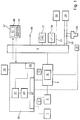
- Fig. 1 shows a simplified block diagram of a field device according to the invention.
- a measuring device This comprises a sensor 1, for detecting a physical measured variable, for example a filling level, a pressure or a temperature, which generates a sensor signal corresponding to the physical measured variable.
- a physical measured variable for example a filling level, a pressure or a temperature
- a signal conditioning 3 which processes the sensor signal for further processing and / or evaluation.
- the signal conditioning 3 can be, for example, that the sensor signal is filtered, amplified and / or digitized.
- a compensation of measurement errors such as a compensation of temperature-dependent deviations can be made.
- stored parameters, characteristic curves and / or calibration data can be used in a memory 5.
- the processed sensor signal is fed to a signal processor 7, which determines the physical quantity to be measured on the basis of the processed sensor signal, and makes available a corresponding output signal via an output unit 9 of the field device.
- the signal processing 7 preferably comprises an electronic unit 11, e.g. a microprocessor on which the conditioned sensor signal is supplied.
- the electronic unit 11 determines the quantity to be measured, for example, by means of calculation instructions stored in a memory 13, wherein it also for example also in the field device, e.g. in the memories 5 and / or 13, stored parameters, characteristics and / or calibration data draws.
- further information can be supplied to the signal processor 7 for determining the physical quantity. This information can be derived within the field device or else be supplied from outside via corresponding interfaces 15. An example of such information is additional measurands or manipulated variables, for example internally in the field device, e.g. are derived from other sensors, or which are supplied via the interface 15 from the outside.
- the output unit 9 comprises, for example, a local display 17, a relay 19, or connecting lines 21, 23 via which the output signal in analog or digital form a superordinate unit 18, eg a programmable logic controller (PLC), a process control system (PLS) or a personal computer (PC ) can be fed.
- a superordinate unit 18 eg a programmable logic controller (PLC), a process control system (PLS) or a personal computer (PC ) can be fed.
- PLC programmable logic controller
- PLS process control system
- PC personal computer
- the output of a digital output signal can be effected, for example, via a data bus line connected to the output unit 9, here the connection line 21.
- a data bus line connected to the output unit 9, here the connection line 21.
- Known international standards for this type of signal transmission are Profibus, Foundation Fieldbus or CAN bus.
- the output of analog output signals is very often via a connected to the output unit 9 line pair, here the two connecting lines 23, via which both the supply of the field device and the output of the output signal.
- These devices are often referred to as 2-wire devices.
- Such devices are supplied with voltages in the range of 12 V to 36 V and the field device controls a current flowing across the line pair in dependence on a current measured value.
- the output signal is a signal current in these field devices.
- the signal current is set to values between a minimum signal current of 4 mA and a maximum signal current of 20 mA as a function of the instantaneous measured value.
- a communication signal can be superimposed on the signal current, via which bidirectional communication with the field device can take place. Also for this purpose are in the measurement and control standard standards, such. Hard, before.
- the field device has a device 25 for carrying out user-defined diagnostic methods.
- This device 25 may be part of the signal processing 7, but it may also be designed as an independent unit. Alternatively, of course, a plurality of decentralized subunits may be arranged at functionally relevant locations in the field device, which are interconnected. In the in Fig. 1 illustrated embodiment, it is shown as a separate unit. The device 25 is in Fig. 2 shown in detail.
- an input circuit 27 via which the device is supplied with at least one input variable E.
- An example of an input variable E is the sensor signal, which can be supplied to the input circuit 27 as a raw signal or in a conditioned form. In the case of fill level measuring devices operating according to the transit time principle, this is, for example, the received echo signal which is supplied as input signal E as raw signal or in processed form, eg in the form of an envelope derived therefrom.
- Another input E are additional measuring or manipulated variables, which are derived, for example, internally in the field device, for example from additional sensors, such as temperature sensors, or which are supplied via the interface 15 from the outside. With a temperature sensor, for example, the temperature of the meter electronics can be determined and provided as an input quantity E.
- the available input quantities E can be supplied in the device 25 to individual or several evaluation methods AV.
- the evaluation methods AV1... AVm available for this purpose are implemented in the field device as modularly usable function blocks which serve to execute the respective evaluation method AV.
- An evaluation unit 29 is connected to the input circuit 27 and serves to derive at least one parameter K based on at least one input variable E selected by the user and at least one evaluation method AV selected by the user.
- the evaluation methods AV include, in particular, averaging, integral formations, summation formations, the determination of extreme values, such as minimum and maximum, the determination of the number or frequency of zero crossings, the derivation of correlation functions or Fourier transforms, as well as the determination of frequencies and / or amplitudes of the input quantities E.
- the evaluation methods AV can be present, for example, in the form of software modules in the field device, which are executed by a microprocessor 31 provided in the evaluation unit 29, to which the input quantities E are supplied in digital form.
- individual or all evaluation methods AV can also be executed by circuits 33 provided specifically for this purpose, which are connected in accordance with the specifications of the user.
- Commercially available prefabricated building blocks, for example, which are specially designed for carrying out specific tasks, can be used for this purpose. Examples include digital signal processors for performing Fourier transforms and filters or similar components that can be used, for example, for signal selection and subsequent processing, for example averaging.
- time available via this internal clock 35 can be made available as a further input variable E.
- the user determines by suitable specifications to the field device which input quantities E in the field device are subjected to which evaluation method AV, and thus specifies the type and number of the characteristic quantities K available at the output of the evaluation unit 29.
- This can be done, for example, such that an input variable E is subjected to an evaluation process AV, which then directly generates the desired characteristic K.
- an input variable E can be subjected to a plurality of evaluation methods AV, wherein each evaluation method AV generates a characteristic variable K in each case. It is likewise possible to apply a plurality of evaluation methods AV in succession by using one or more parameters K generated by an evaluation method AV as input variables E for a further evaluation method AV.
- the parameters K are fed to a monitoring unit 37.
- monitoring criteria UK are available to the user, to which the parameters K can be checked.
- the monitoring criteria UK are implemented in the field device as modules UK 1 ... UK n , which serve to monitor the application of the respective monitoring criterion UK.
- Such a monitoring criterion UK is, for example, above or below a threshold defined by the user.
- a monitoring criterion UK may contain a single condition, but it may also be composed of several subcriteria, for example defined by logical links, such as e.g. AND and / or OR links, are connected together to form a criterion.
- the user has the option of combining several monitoring criteria UK with each other by another monitoring criterion UK or by logical links.
- the monitoring criteria UK may e.g. in the form of software modules in the field device, which are checked by a microprocessor 39 provided in the monitoring unit 37, to which the parameters K generated in accordance with the specifications of the user are supplied in digital form.
- individual or all monitoring criteria UK can also be checked by specially provided circuits 41, which are connected according to the specifications of the user.
- commercially available prefabricated building blocks such as e.g. Comparators, are used.
- a diagnostic output 43 is connected to the monitoring unit 37 and outputs a diagnosis D associated with this monitoring criterion UK when a monitoring criterion UK, such as the exceeding of a threshold value, occurs.
- the diagnosis D to be provided upon the occurrence of the respective monitoring criterion UK is predefined by the user and stored in a memory 56. It includes, for example, a user-specified in the memory 56 stored message containing the error or condition to be diagnosed denotes, for example, 'amplitude of the sensor signal exceeds limit value'.
- each diagnosis D preferably includes a cause also stored by the user in the memory 56 stored cause and / or a remedial action, which is issued as part of the diagnosis D together with the message.
- the user knows his process very precisely and therefore knows which input quantities E contain important information for his application and how this information can be obtained. He has now for the first time by the field device according to the invention the possibility to have this information determined by the definition of a corresponding user-defined diagnostic method directly from the field device and display in the form of an optimally adapted for his application diagnosis D, in which he both the name of the error or condition, as well as its cause and possible remedies.
- the output of the diagnosis D preferably takes place via the output unit 9.
- the output unit 9 can have a separate output 45, via which the diagnoses D are output.
- it can also be transmitted via the same output, via which the measuring signal is also transmitted, for example, by being output via the bus line 21 or being superimposed on the signal current in the connecting lines 23 in the form of a communication signal.
- the field device has an interface 47 via which a user selects the input quantities E x for each user-defined diagnostic method X desired by him, selects the evaluation method AV x to be used for the input quantities E x , selects the monitoring criteria UK x , and sets the diagnosis D x pretends.
- the interface 47 is in the in Fig. 1 illustrated embodiment with a directly on the field device arranged user interface with a display 49 and an input device 51, such as a keypad, connected.
- the interface 47 is connected to the output unit 9 and allows via the output unit 9 a bidirectional communication with the field device. Via this bidirectional connection, the user receives information that he needs to specify his user-defined diagnostic procedure.
- interfaces are used which the field device already possesses.
- the interface can be integrated in the higher-level unit 24, for example.
- a user interface with a display and an input device is regularly provided anyway, via which the user communicates with the field device.
- the user receives via the higher-level unit 24 the possibility of specifying his user-defined diagnostic method.
- a mobile operating tool 55 that can be connected to the connecting lines 23 of the output unit 9 and communicates with the field device via a communication signal superimposed on the signal stream is suitable as the interface.
- At least one memory 56 is provided in the field device, in which the input variables E 1 ... E L available for the user-defined diagnostic methods, the available evaluation methods AV 1 ... AV m , and the available monitoring criteria UK 1 ... UK n are listed.
- the interface 47 has a display, here for example the display 49, which serves to provide the user with the available information Input variables E 1 ... E L , the available evaluation methods AV 1 ... AV m and the available monitoring criteria UK 1 ... UK n display, and it has an input device, here the input device 51, on
- the user specifies the associated input variables E x , evaluation method AV x , monitoring criteria UK x , and the diagnosis D x .
- These specifications are stored in the field device, for example in the memory 56, where they are retrieved by the evaluation unit 29, the monitoring unit 37 and the diagnostic output 43.
- the implementation of a user-defined diagnostic method preferably takes place in a menu-guided form during the commissioning of the field device.
- the procedure is preferably such that the user places the field device in a mode for implementing a user-defined diagnostic method.
- the user first receives the available input variables E 1 ... E L listed in the memory 56.
- the user selects from the available input variables E 1 ... E L the input variables E x that are relevant for his diagnostic method X and stores them in the field device, here in the memory 56.
- the user is presented with the evaluation methods AV 1 ... AV m listed in the memory 56. From the available evaluation methods AV 1 ...
- the user selects the evaluation method AV x that is relevant for his diagnostic method X and specifies to which of the selected input quantities E x they should be applied. These inputs are also stored in the memory 56. Examples of this are in Fig. 2 shown. This results directly in the type and number of the evaluation unit 29 in the context of this diagnostic method X to be generated parameters K x . These can be determined automatically by the device, for example, by means of a corresponding software module implemented in the field device.
- an evaluation method AV is selected, for its execution additional information, such as a period of time, over which an averaging is to be executed, threshold values, reference values or reference values are required, the user is prompted immediately after the selection of this evaluation method AV to supplement the required information with appropriate inputs.
- a next step the user selects from the available monitoring criteria UK 1 ... UK n the monitoring criteria UK x that are relevant for his diagnostic method X and in each case specifies the parameter K to which it is to be applied.
- this step can be carried out, for example, such that the field device internally determines the type and number of characteristics K x , and displays the user K for each characteristic, based on which input quantities E they derive and of which evaluation methods AV they is generated and the user acknowledges each of these displays by selecting the monitoring criteria UK to apply to each characteristic K.
- These specifications are then stored accordingly in the memory 56 in the field device. If a monitoring criterion UK is selected, the execution of which requires additional information such as thresholds, reference values or reference values, the user will be prompted immediately after the selection of this monitoring criterion UK to supplement the required information with corresponding inputs.
- the user specifies an associated diagnosis D x , which is output from the diagnostic output 43 when this monitoring criterion UK x occurs .
- an associated diagnosis D x which is output from the diagnostic output 43 when this monitoring criterion UK x occurs .
- the text may include the cause of the error or condition and / or the indication of a remedial action.
- Such a message text may be, for example: rate of change of the level too low; Supply line clogged; Please carry out system cleaning '.
- each diagnosis D x can be associated with a safety-related response of the field device to the occurrence of the respective state or fault that is triggered by the corresponding diagnosis D x in the device.
- a reaction is, for example, the triggering of an alarm or the freezing of the measurement results.
- Such reactions can be made available to the user as function blocks, which the user can assign to his diagnoses D x when implementing his diagnostic method.
- the implementation of the user-defined diagnostic procedure is very simple and quick to carry out, since the user only has to specify the structure and the sequence.
- the individual evaluation methods and monitoring criteria are available as flexible modules in the field device and do not have to be created by the user.
- a very simple diagnostic method consists in determining the operating time of the field device as parameter K in an evaluation method AV on the basis of the time provided by the internal clock as input variable E.
- the corresponding monitoring criterion UK is in this case the exceeding of a permissible operating time. If this monitoring criterion occurs, the diagnosis will be e.g. a maintenance requirement issued.
- the input E for example, the echo signal of a running on the transit time principle level gauge in which electromagnetic signals are guided along a waveguide selected.
- This input quantity E is subjected to an evaluation method AV, which determines the amplitude of an echo caused by a reflection at the waveguide end as a parameter K.
- the monitoring criterion UK determines whether the amplitude has a positive polarity. This is the case when condensate jumps to a smaller waveguide impedance, while without condensate the free end of the probe produces a negative signal by jumping to a larger waveguide impedance. If the monitoring criterion occurs, the diagnosis is the presence of condensate in the tank.
- a diagnostic method allows, for example, the detection of foam on the product surface.
- the echo signal is also used as the input variable E.
- AV1 the amplitude of the echo originating from the reflection at the product surface is determined as parameter K1.
- K1 is determined by means of a corresponding monitoring criterion UK1, whether this amplitude is small.
- the monitoring criterion UK1 is eg a comparison of the characteristic K1 with a reference value.
- a small amplitude of the level echo may be due either to the presence of foam or to a low dielectric constant product.
- the input variable E is subjected to a second evaluation method AV2, which determines the amplitude of an echo caused by reflection at the waveguide end as a further characteristic K2.
- AV2 determines the amplitude of an echo caused by reflection at the waveguide end as a further characteristic K2.
- this second characteristic K2 it is determined by means of a corresponding monitoring criterion UK1 whether the amplitude of the reflection originating from the waveguide end falls below a predetermined reference value or whether no such echo is present. If this is the case, the contents have a high dielectric constant.
- the final diagnosis then results from the logical combination of the two monitoring criteria. If both monitoring criteria UK1 and UK2 are met, foam on the product surface is diagnosed as the cause of the low amplitude of the echo originating from the product surface.
- the field device automatically carries out tailor-made diagnostic methods for its application and only supplies a diagnosis if an error or condition to be diagnosed actually occurs. If this is not the case, no communication with the field device is required in this context.
Landscapes
- Physics & Mathematics (AREA)
- General Physics & Mathematics (AREA)
- Engineering & Computer Science (AREA)
- Automation & Control Theory (AREA)
- Testing And Monitoring For Control Systems (AREA)
- Testing Or Calibration Of Command Recording Devices (AREA)
Claims (9)
- Appareil de terrain avec- un dispositif destiné à l'exécution de procédures de diagnostic (25) définies par l'utilisateur,-- lequel dispositif comprend un circuit d'entrée (27), par l'intermédiaire duquel au moins une grandeur d'entrée (E) est acheminée au dispositif (25),-- lequel dispositif comprend une unité d'exploitation (29),--- qui sert, au moyen d'au moins une grandeur d'entrée (Ex) sélectionnée par l'utilisateur et au moyen d'au moins une procédure d'exploitation (AVx) sélectionnée par l'utilisateur, de déduire au moins une grandeur caractéristique (Kx),-- lequel dispositif comprend une unité de surveillance (37),--- qui est configurée de manière à surveiller les grandeurs caractéristiques (Kx) dérivées au moyen de critères de surveillance (UKx) sélectionnés par l'utilisateur, et-- lequel dispositif comprend une unité de sortie (43), configuré, en cas de survenue d'un critère de surveillance (UKx), de telle manière à délivrer un diagnostic (Dx) attribué à ce critère de surveillance (UKx), et- une interface, configurée de telle manière qu'un utilisateur sélectionne par le biais de celle-ci, pour chaque procédure de diagnostic définie par l'utilisateur,caractérisé--- les grandeurs d'entrée (Ex),--- les procédures d'exploitation à utiliser pour les grandeurs d'entrée (Ex),--- les critères de surveillance (UKx), et--- spécifie le diagnostic (Dx) pour la sortie par l'intermédiaire de l'unité de sortie (43),
en ce que les procédures d'exploitation (AVx) disponibles sont réalisées dans l'appareil de terrain en tant que blocs fonctionnels utilisables de façon modulaire, sont implémentées de façon fixe dans l'appareil de terrain dans les blocs fonctionnels correspondants, sont activées au moyen de spécifications appropriées de l'utilisateur et sont appliquées aux grandeurs d'entrée (Ex) sélectionnées par l'utilisateur, et en ce que chaque critère de surveillance (UK1 ... UKn) est prévu en tant que module dans l'appareil de terrain. - Appareil de terrain selon la revendication 1, pour lequel- est prévue au moins une mémoire (56), dans laquelle sont répertoriées les grandeurs d'entrée (E1 ... En) disponibles, les procédures d'exploitation (AV1 ... AVm) disponibles et les critères de surveillance (UK1 ... UKn) disponibles,- l'interface (47) est reliée avec l'afficheur (49), qui sert à afficher les grandeurs d'entrée (E1 ... En) disponibles, les procédures d'exploitation (AV1 ... AVm) disponibles et les critères de surveillance (UK1 ... UKn) disponibles pour l'utilisateur, et- l'interface (47) est reliée avec un dispositif d'entrée (51), par l'intermédiaire duquel l'utilisateur spécifie pour chaque procédure de diagnostic définie par l'utilisateur les grandeurs d'entrée (Ex), les procédures d'exploitation (AVx), les procédures de surveillance (UKx) et les diagnostics (Dx).
- Appareil de terrain selon la revendication 1, pour lequel les procédures d'exploitation (AV) comprennent des exploitations statiques.
- Appareil de terrain selon la revendication 1, pour lequel les critères de surveillance (UK) comprennent des comparaisons et des combinaisons logiques.
- Appareil de terrain selon la revendication 1, pour lequel une horloge interne (35) est attribuée à l'unité d'exploitation (29).
- Appareil de terrain selon la revendication 1, pour lequel l'interface (47) est reliée avec une interface utilisateur disposée directement sur l'appareil de terrain, laquelle interface utilisateur comporte un afficheur (49) et un dispositif d'entrée (51).
- Appareil de terrain selon la revendication 1, pour lequel le diagnostic (D) comprend un message dont le contenu est spécifié par l'utilisateur, enregistré dans une mémoire (56) au sein de l'appareil de terrain, message désignant une erreur ou un état à diagnostiquer.
- Appareil de terrain selon la revendication 7, pour lequel le diagnostic comprend une cause et/ou une mesure corrective dont le contenu est/sont spécifié(s) par l'utilisateur, enregistrée(s) dans une mémoire (56) au sein de l'appareil de terrain, laquelle cause et/ou laquelle mesure corrective est/sont délivrée(s) conjointement avec le message correspondant.
- Procédé destiné à l'implémentation d'une procédure de diagnostic définie par l'utilisateur dans un appareil de terrain selon l'une des revendications précédentes, pour lequel- l'utilisateur sélectionne, à partir des grandeurs d'entrée (E1 ... EL) disponibles, les grandeurs d'entrées (Ex) pertinentes pour sa procédure de diagnostic (X), et les enregistre dans l'appareil de terrain,- l'utilisateur sélectionne, à partir des procédures d'exploitation (AV1 ... AVm) disponibles, les procédures d'exploitation (AVx) pertinentes pour sa procédure de diagnostic (X), et spécifie à quelles grandeurs d'entrée (Ex) sélectionnées elles doivent être appliquées,- l'utilisateur sélectionne, à partir des critères de surveillance (UK1 ... UKn) disponibles, les critères de surveillance (UKx) pertinents pour sa procédure de diagnostic (X), et spécifie la grandeur caractéristique (K) à laquelle elles doivent être appliquées, et- l'utilisateur spécifie pour chaque critère de surveillance (UKx) un diagnostic (Dx) correspondant, qui est délivré à chaque survenue de ce critère de surveillance (UKx) par l'unité de sortie de diagnostic (43),caractérisé
en ce que les procédures d'exploitation (AVx) disponibles sont réalisées dans l'appareil de terrain en tant que blocs fonctionnels utilisables de façon modulaire, les différentes procédures d'exploitation (AVx) sont implémentées de façon fixe dans les blocs fonctionnels correspondants au sein de l'appareil de terrain, sont activées au moyen de spécifications appropriées de l'utilisateur et sont appliquées aux grandeurs d'entrée (Ex) sélectionnées par l'utilisateur,
et en ce que chaque critère de surveillance (UK1 ... UKn) est prévu en tant que module dans l'appareil de terrain.
Applications Claiming Priority (2)
| Application Number | Priority Date | Filing Date | Title |
|---|---|---|---|
| DE102007027276A DE102007027276A1 (de) | 2007-06-11 | 2007-06-11 | Feldgerät mit einer Vorrichtung zur Durchführung von Diagnoseverfahren |
| PCT/EP2008/056899 WO2008151971A1 (fr) | 2007-06-11 | 2008-06-04 | Appareil de terrain comprenant une unité de mise en oeuvre de procédés de diagnostics |
Publications (2)
| Publication Number | Publication Date |
|---|---|
| EP2156251A1 EP2156251A1 (fr) | 2010-02-24 |
| EP2156251B1 true EP2156251B1 (fr) | 2017-08-09 |
Family
ID=39873955
Family Applications (1)
| Application Number | Title | Priority Date | Filing Date |
|---|---|---|---|
| EP08760481.5A Not-in-force EP2156251B1 (fr) | 2007-06-11 | 2008-06-04 | Appareil de terrain comprenant une unité de mise en oeuvre de procédés de diagnostics |
Country Status (4)
| Country | Link |
|---|---|
| US (1) | US8683366B2 (fr) |
| EP (1) | EP2156251B1 (fr) |
| DE (1) | DE102007027276A1 (fr) |
| WO (1) | WO2008151971A1 (fr) |
Families Citing this family (18)
| Publication number | Priority date | Publication date | Assignee | Title |
|---|---|---|---|---|
| US20100274528A1 (en) * | 2009-04-22 | 2010-10-28 | Rosemount Inc. | Field device with measurement accuracy reporting |
| DE102009046691B4 (de) * | 2009-11-13 | 2013-06-06 | Balluff Gmbh | Sensorvorrichtung |
| EP2386920A1 (fr) * | 2010-05-06 | 2011-11-16 | Siemens Aktiengesellschaft | Procédé d'évaluation d'alertes de diagnostic |
| DE102010044184B4 (de) * | 2010-11-19 | 2018-05-09 | Endress + Hauser Process Solutions Ag | Verfahren und Kommunikationseinheit zum Erstellen einer Diagnose eines Feldgerätes |
| DE102010063430A1 (de) * | 2010-12-17 | 2012-06-21 | Endress + Hauser Gmbh + Co. Kg | Verfahren zur Überwachung der Funktion eines Feldgeräts |
| CN103748524A (zh) * | 2011-03-31 | 2014-04-23 | Abb技术有限公司 | 工程设计并诊断现场装置的方法及其系统 |
| DE102011075764A1 (de) | 2011-05-12 | 2012-11-29 | Endress + Hauser Gmbh + Co. Kg | Bewertungsvorrichtung für Feldgerätparameter |
| US8744604B2 (en) * | 2012-05-09 | 2014-06-03 | Fisher Controls International Llc | Method and apparatus for configuring a blackout period for scheduled diagnostic checks of a field device in a process plant |
| DE202012006550U1 (de) * | 2012-07-06 | 2012-08-06 | Abb Technology Ag | Prozessleitsystem |
| DE102013100799A1 (de) * | 2012-12-21 | 2014-06-26 | Endress + Hauser Flowtec Ag | Umformerschaltung mit einer Stromschnittstelle sowie Meßgerät mit einer solchen Umformerschaltung |
| EP2799946B1 (fr) * | 2013-05-03 | 2016-10-05 | Pepperl + Fuchs GmbH | Procédé de réalisation d'une compatibilité entre d'un appareil de terrain et un dispositif de diagnostique et dispositif d'interface |
| EP2803956A1 (fr) * | 2013-05-13 | 2014-11-19 | VEGA Grieshaber KG | Module de service pour un appareil de mesure du niveau de remplissage et procédé de service automatisé |
| JP2016027457A (ja) | 2014-06-26 | 2016-02-18 | 横河電機株式会社 | 電子機器 |
| DE102015011910A1 (de) * | 2015-09-11 | 2017-03-16 | Kuka Roboter Gmbh | Verfahren und System zum Steuern einer Roboteranordnung |
| US9915167B2 (en) * | 2015-11-20 | 2018-03-13 | Ansaldo Energia Switzerland AG | Detection of deficient sensors in a gas turbine system |
| DE102018110084A1 (de) * | 2018-04-26 | 2019-10-31 | Fibro Gmbh | Diagnoseeinheit |
| DE102018129590A1 (de) * | 2018-11-23 | 2020-05-28 | Endress + Hauser Wetzer Gmbh + Co. Kg | Feldgerät mit prozessspezifischer Zustandsüberwachung |
| DE102023101668A1 (de) | 2023-01-24 | 2024-07-25 | Krohne Messtechnik Gmbh | Verfahren zum Betreiben eines Feldgerätes der Prozessmesstechnik und Abfüllanlage, mit der das Verfahren ausgeführt wird |
Family Cites Families (22)
| Publication number | Priority date | Publication date | Assignee | Title |
|---|---|---|---|---|
| US5311562A (en) * | 1992-12-01 | 1994-05-10 | Westinghouse Electric Corp. | Plant maintenance with predictive diagnostics |
| DE19537694A1 (de) * | 1995-10-10 | 1997-04-17 | Schenck Ag Carl | Verfahren zur Überwachung einer Maschine oder Anlage |
| US5844795A (en) * | 1995-11-01 | 1998-12-01 | Allen Bradley Company, Llc | Diagnostic aid for industrial controller using multi-tasking architecture |
| US6017143A (en) | 1996-03-28 | 2000-01-25 | Rosemount Inc. | Device in a process system for detecting events |
| JP3617196B2 (ja) * | 1996-07-02 | 2005-02-02 | 豊田工機株式会社 | 数値制御装置 |
| US6298308B1 (en) | 1999-05-20 | 2001-10-02 | Reid Asset Management Company | Diagnostic network with automated proactive local experts |
| EP1348296B8 (fr) * | 2000-12-01 | 2006-08-16 | Magus Intellectual Property GmbH | Surveillance d'etat de machine a commande incorporee |
| IT1319716B1 (it) * | 2000-12-28 | 2003-11-03 | Abb Ricerca Spa | Sistema computerizzato per effettuare operazioni di configurazione ediagnostica remota su un dispositivo di campo |
| US6973410B2 (en) * | 2001-05-15 | 2005-12-06 | Chillergy Systems, Llc | Method and system for evaluating the efficiency of an air conditioning apparatus |
| US7050863B2 (en) * | 2002-09-11 | 2006-05-23 | Fisher-Rosemount Systems, Inc. | Integrated model predictive control and optimization within a process control system |
| DE10252892A1 (de) * | 2002-11-12 | 2004-06-09 | Endress + Hauser Process Solutions Ag | Verfahren zur Diagnose von Feldgeräten der Prozessautomatisierungsechnik |
| DE10255288A1 (de) * | 2002-11-26 | 2004-07-08 | Endress + Hauser Gmbh + Co. Kg | Verfahren zur Bestimmung des Zustandes eines Fleldmessgerätes für die Prozessautomatisierung und Prozessmesstechnik und Feldmessgerät zur Durchführung des Verfahrens |
| US7003417B2 (en) * | 2003-06-06 | 2006-02-21 | Invensys Systems, Inc. | Multiple calibration ranges stored in a process transmitter |
| US7024319B2 (en) * | 2003-07-17 | 2006-04-04 | Endress & Hauser Gmbh & Co. Kg | Device for determining and/or monitoring a process parameter |
| US7363195B2 (en) * | 2004-07-07 | 2008-04-22 | Sensarray Corporation | Methods of configuring a sensor network |
| DE102004036957B3 (de) * | 2004-07-30 | 2006-06-14 | Infineon Technologies Ag | Verfahren zum Erzeugen von Testsignalen und Verwendung eines Testsystems zur Durchführung des Verfahrens |
| US7349746B2 (en) * | 2004-09-10 | 2008-03-25 | Exxonmobil Research And Engineering Company | System and method for abnormal event detection in the operation of continuous industrial processes |
| DE102004055472A1 (de) * | 2004-11-17 | 2006-06-14 | Siemens Ag | Mittel zur Selektion eines statistischen Auswerteverfahrens für eine empirische Untersuchung |
| DE102005041632A1 (de) * | 2005-09-01 | 2007-03-08 | Siemens Ag | Verfahren und Vorrichtung zur Überwachung einer technischen Einrichtung |
| DE102005051769A1 (de) * | 2005-10-27 | 2007-05-03 | Endress + Hauser Flowtec Ag | Vorrichtung zum Betreiben einer Prozessanlage |
| US20080065706A1 (en) * | 2006-09-12 | 2008-03-13 | Fisher-Rosemount Systems, Inc. | Process Data Storage For Process Plant Diagnostics Development |
| US8489360B2 (en) * | 2006-09-29 | 2013-07-16 | Fisher-Rosemount Systems, Inc. | Multivariate monitoring and diagnostics of process variable data |
-
2007
- 2007-06-11 DE DE102007027276A patent/DE102007027276A1/de not_active Withdrawn
-
2008
- 2008-06-04 WO PCT/EP2008/056899 patent/WO2008151971A1/fr not_active Ceased
- 2008-06-04 EP EP08760481.5A patent/EP2156251B1/fr not_active Not-in-force
- 2008-06-04 US US12/663,839 patent/US8683366B2/en active Active
Non-Patent Citations (1)
| Title |
|---|
| None * |
Also Published As
| Publication number | Publication date |
|---|---|
| US20100169816A1 (en) | 2010-07-01 |
| WO2008151971A1 (fr) | 2008-12-18 |
| EP2156251A1 (fr) | 2010-02-24 |
| US8683366B2 (en) | 2014-03-25 |
| DE102007027276A1 (de) | 2008-12-18 |
Similar Documents
| Publication | Publication Date | Title |
|---|---|---|
| EP2156251B1 (fr) | Appareil de terrain comprenant une unité de mise en oeuvre de procédés de diagnostics | |
| EP2153288B1 (fr) | Appareil de terrain | |
| DE102008036968A1 (de) | Diagnoseverfahren eines Prozessautomatisierungssystem | |
| DE102019216393A1 (de) | Feldgerät zur prozessautomatisierung im industriellen umfeld | |
| EP2338091B1 (fr) | Procédé pour l'adaptation dynamique d'un système de diagnostic | |
| DE102010044184B4 (de) | Verfahren und Kommunikationseinheit zum Erstellen einer Diagnose eines Feldgerätes | |
| WO2012079992A1 (fr) | Procédé pour surveiller le fonctionnement d'un appareil de terrain | |
| DE102016120444A1 (de) | Verfahren zum Betreiben eines Feldgerätes für die Automatisierungstechnik | |
| EP2021736B1 (fr) | Transducteur de mesure | |
| DE102012109132A1 (de) | Verbessertes Verfahren und verbesserte Vorrichtung zur Vermeidung von Aliasing | |
| WO2010046246A1 (fr) | Procédé et dispositif pour la détection d'états de processus dans des processus de production alternés | |
| EP3282233B1 (fr) | Procédé de fonctionnement d'un appareil de mesure de niveau de remplissage et appareil de mesure de niveau de remplissage | |
| DE102010044186A1 (de) | Verfahren zum Bereitstellen einer Feldgerätetyp-übergreifenden Diagnosemeldung | |
| EP4018277B1 (fr) | Transmission des valeurs mesurées de processus orientée événements | |
| DE10326627A1 (de) | Verfahren zur Funktionsanzeige eines Feldgerätes der Prozessautomatisierungstechnik | |
| EP4002040B1 (fr) | Procédé de surveillance des grandeurs de mesure mesurées à l'aide d'un appareil de mesure dans une installation technique | |
| DE102011075764A1 (de) | Bewertungsvorrichtung für Feldgerätparameter | |
| DE102004048766A1 (de) | Feldbusanwendung mit mehreren Feldgeräten | |
| EP3692422A1 (fr) | Montre intelligente et procédé de maintenance d'une installation de la technique d'automatisation | |
| DE102018129944B4 (de) | Verfahren zum Überwachen eines Automatisierungssystems | |
| EP3555714B1 (fr) | Procédé de réglage, spécifique à une application, d'un appareil de terrain | |
| DE202009010293U1 (de) | Elektronisches Auswertemodul für Sensorsignale | |
| DE102008033336B4 (de) | Verfahren zur Überprüfung eines Messgerätes | |
| EP4323845B1 (fr) | Procédé de contrôle d'un trajet de signal d'un circuit de capteur électronique pour un appareil de terrain dans une technologie d'automatisation | |
| DE102005029615A1 (de) | Verfahren zur Erkennung von Bauteilefehlern einer analogen Signalverarbeitungsschaltung insbesondere für einen Messumformer |
Legal Events
| Date | Code | Title | Description |
|---|---|---|---|
| PUAI | Public reference made under article 153(3) epc to a published international application that has entered the european phase |
Free format text: ORIGINAL CODE: 0009012 |
|
| 17P | Request for examination filed |
Effective date: 20091109 |
|
| AK | Designated contracting states |
Kind code of ref document: A1 Designated state(s): AT BE BG CH CY CZ DE DK EE ES FI FR GB GR HR HU IE IS IT LI LT LU LV MC MT NL NO PL PT RO SE SI SK TR |
|
| AX | Request for extension of the european patent |
Extension state: AL BA MK RS |
|
| 17Q | First examination report despatched |
Effective date: 20100413 |
|
| DAX | Request for extension of the european patent (deleted) | ||
| GRAP | Despatch of communication of intention to grant a patent |
Free format text: ORIGINAL CODE: EPIDOSNIGR1 |
|
| INTG | Intention to grant announced |
Effective date: 20170208 |
|
| GRAS | Grant fee paid |
Free format text: ORIGINAL CODE: EPIDOSNIGR3 |
|
| GRAA | (expected) grant |
Free format text: ORIGINAL CODE: 0009210 |
|
| AK | Designated contracting states |
Kind code of ref document: B1 Designated state(s): AT BE BG CH CY CZ DE DK EE ES FI FR GB GR HR HU IE IS IT LI LT LU LV MC MT NL NO PL PT RO SE SI SK TR |
|
| REG | Reference to a national code |
Ref country code: GB Ref legal event code: FG4D Free format text: NOT ENGLISH |
|
| REG | Reference to a national code |
Ref country code: CH Ref legal event code: EP Ref country code: AT Ref legal event code: REF Ref document number: 917499 Country of ref document: AT Kind code of ref document: T Effective date: 20170815 |
|
| REG | Reference to a national code |
Ref country code: IE Ref legal event code: FG4D Free format text: LANGUAGE OF EP DOCUMENT: GERMAN |
|
| REG | Reference to a national code |
Ref country code: DE Ref legal event code: R096 Ref document number: 502008015522 Country of ref document: DE |
|
| REG | Reference to a national code |
Ref country code: NL Ref legal event code: MP Effective date: 20170809 |
|
| REG | Reference to a national code |
Ref country code: LT Ref legal event code: MG4D |
|
| PG25 | Lapsed in a contracting state [announced via postgrant information from national office to epo] |
Ref country code: LT Free format text: LAPSE BECAUSE OF FAILURE TO SUBMIT A TRANSLATION OF THE DESCRIPTION OR TO PAY THE FEE WITHIN THE PRESCRIBED TIME-LIMIT Effective date: 20170809 Ref country code: FI Free format text: LAPSE BECAUSE OF FAILURE TO SUBMIT A TRANSLATION OF THE DESCRIPTION OR TO PAY THE FEE WITHIN THE PRESCRIBED TIME-LIMIT Effective date: 20170809 Ref country code: NO Free format text: LAPSE BECAUSE OF FAILURE TO SUBMIT A TRANSLATION OF THE DESCRIPTION OR TO PAY THE FEE WITHIN THE PRESCRIBED TIME-LIMIT Effective date: 20171109 Ref country code: SE Free format text: LAPSE BECAUSE OF FAILURE TO SUBMIT A TRANSLATION OF THE DESCRIPTION OR TO PAY THE FEE WITHIN THE PRESCRIBED TIME-LIMIT Effective date: 20170809 Ref country code: NL Free format text: LAPSE BECAUSE OF FAILURE TO SUBMIT A TRANSLATION OF THE DESCRIPTION OR TO PAY THE FEE WITHIN THE PRESCRIBED TIME-LIMIT Effective date: 20170809 Ref country code: HR Free format text: LAPSE BECAUSE OF FAILURE TO SUBMIT A TRANSLATION OF THE DESCRIPTION OR TO PAY THE FEE WITHIN THE PRESCRIBED TIME-LIMIT Effective date: 20170809 |
|
| PG25 | Lapsed in a contracting state [announced via postgrant information from national office to epo] |
Ref country code: ES Free format text: LAPSE BECAUSE OF FAILURE TO SUBMIT A TRANSLATION OF THE DESCRIPTION OR TO PAY THE FEE WITHIN THE PRESCRIBED TIME-LIMIT Effective date: 20170809 Ref country code: LV Free format text: LAPSE BECAUSE OF FAILURE TO SUBMIT A TRANSLATION OF THE DESCRIPTION OR TO PAY THE FEE WITHIN THE PRESCRIBED TIME-LIMIT Effective date: 20170809 Ref country code: GR Free format text: LAPSE BECAUSE OF FAILURE TO SUBMIT A TRANSLATION OF THE DESCRIPTION OR TO PAY THE FEE WITHIN THE PRESCRIBED TIME-LIMIT Effective date: 20171110 Ref country code: BG Free format text: LAPSE BECAUSE OF FAILURE TO SUBMIT A TRANSLATION OF THE DESCRIPTION OR TO PAY THE FEE WITHIN THE PRESCRIBED TIME-LIMIT Effective date: 20171109 Ref country code: PL Free format text: LAPSE BECAUSE OF FAILURE TO SUBMIT A TRANSLATION OF THE DESCRIPTION OR TO PAY THE FEE WITHIN THE PRESCRIBED TIME-LIMIT Effective date: 20170809 Ref country code: IS Free format text: LAPSE BECAUSE OF FAILURE TO SUBMIT A TRANSLATION OF THE DESCRIPTION OR TO PAY THE FEE WITHIN THE PRESCRIBED TIME-LIMIT Effective date: 20171209 |
|
| REG | Reference to a national code |
Ref country code: DE Ref legal event code: R081 Ref document number: 502008015522 Country of ref document: DE Owner name: ENDRESS+HAUSER SE+CO. KG, DE Free format text: FORMER OWNER: ENDRESS + HAUSER GMBH + CO. KG, 79689 MAULBURG, DE |
|
| RAP2 | Party data changed (patent owner data changed or rights of a patent transferred) |
Owner name: ENDRESS+HAUSER SE+CO. KG |
|
| PG25 | Lapsed in a contracting state [announced via postgrant information from national office to epo] |
Ref country code: RO Free format text: LAPSE BECAUSE OF FAILURE TO SUBMIT A TRANSLATION OF THE DESCRIPTION OR TO PAY THE FEE WITHIN THE PRESCRIBED TIME-LIMIT Effective date: 20170809 Ref country code: CZ Free format text: LAPSE BECAUSE OF FAILURE TO SUBMIT A TRANSLATION OF THE DESCRIPTION OR TO PAY THE FEE WITHIN THE PRESCRIBED TIME-LIMIT Effective date: 20170809 Ref country code: DK Free format text: LAPSE BECAUSE OF FAILURE TO SUBMIT A TRANSLATION OF THE DESCRIPTION OR TO PAY THE FEE WITHIN THE PRESCRIBED TIME-LIMIT Effective date: 20170809 |
|
| REG | Reference to a national code |
Ref country code: DE Ref legal event code: R097 Ref document number: 502008015522 Country of ref document: DE |
|
| PG25 | Lapsed in a contracting state [announced via postgrant information from national office to epo] |
Ref country code: IT Free format text: LAPSE BECAUSE OF FAILURE TO SUBMIT A TRANSLATION OF THE DESCRIPTION OR TO PAY THE FEE WITHIN THE PRESCRIBED TIME-LIMIT Effective date: 20170809 Ref country code: EE Free format text: LAPSE BECAUSE OF FAILURE TO SUBMIT A TRANSLATION OF THE DESCRIPTION OR TO PAY THE FEE WITHIN THE PRESCRIBED TIME-LIMIT Effective date: 20170809 Ref country code: SK Free format text: LAPSE BECAUSE OF FAILURE TO SUBMIT A TRANSLATION OF THE DESCRIPTION OR TO PAY THE FEE WITHIN THE PRESCRIBED TIME-LIMIT Effective date: 20170809 |
|
| PLBE | No opposition filed within time limit |
Free format text: ORIGINAL CODE: 0009261 |
|
| STAA | Information on the status of an ep patent application or granted ep patent |
Free format text: STATUS: NO OPPOSITION FILED WITHIN TIME LIMIT |
|
| REG | Reference to a national code |
Ref country code: FR Ref legal event code: PLFP Year of fee payment: 11 |
|
| 26N | No opposition filed |
Effective date: 20180511 |
|
| PG25 | Lapsed in a contracting state [announced via postgrant information from national office to epo] |
Ref country code: SI Free format text: LAPSE BECAUSE OF FAILURE TO SUBMIT A TRANSLATION OF THE DESCRIPTION OR TO PAY THE FEE WITHIN THE PRESCRIBED TIME-LIMIT Effective date: 20170809 |
|
| PG25 | Lapsed in a contracting state [announced via postgrant information from national office to epo] |
Ref country code: MT Free format text: LAPSE BECAUSE OF FAILURE TO SUBMIT A TRANSLATION OF THE DESCRIPTION OR TO PAY THE FEE WITHIN THE PRESCRIBED TIME-LIMIT Effective date: 20170809 |
|
| REG | Reference to a national code |
Ref country code: CH Ref legal event code: PL |
|
| REG | Reference to a national code |
Ref country code: BE Ref legal event code: MM Effective date: 20180630 |
|
| REG | Reference to a national code |
Ref country code: IE Ref legal event code: MM4A |
|
| PG25 | Lapsed in a contracting state [announced via postgrant information from national office to epo] |
Ref country code: LU Free format text: LAPSE BECAUSE OF NON-PAYMENT OF DUE FEES Effective date: 20180604 Ref country code: MC Free format text: LAPSE BECAUSE OF FAILURE TO SUBMIT A TRANSLATION OF THE DESCRIPTION OR TO PAY THE FEE WITHIN THE PRESCRIBED TIME-LIMIT Effective date: 20170809 |
|
| PG25 | Lapsed in a contracting state [announced via postgrant information from national office to epo] |
Ref country code: LI Free format text: LAPSE BECAUSE OF NON-PAYMENT OF DUE FEES Effective date: 20180630 Ref country code: IE Free format text: LAPSE BECAUSE OF NON-PAYMENT OF DUE FEES Effective date: 20180604 Ref country code: CH Free format text: LAPSE BECAUSE OF NON-PAYMENT OF DUE FEES Effective date: 20180630 |
|
| PG25 | Lapsed in a contracting state [announced via postgrant information from national office to epo] |
Ref country code: BE Free format text: LAPSE BECAUSE OF NON-PAYMENT OF DUE FEES Effective date: 20180630 |
|
| REG | Reference to a national code |
Ref country code: AT Ref legal event code: MM01 Ref document number: 917499 Country of ref document: AT Kind code of ref document: T Effective date: 20180604 |
|
| PG25 | Lapsed in a contracting state [announced via postgrant information from national office to epo] |
Ref country code: AT Free format text: LAPSE BECAUSE OF NON-PAYMENT OF DUE FEES Effective date: 20180604 |
|
| PG25 | Lapsed in a contracting state [announced via postgrant information from national office to epo] |
Ref country code: TR Free format text: LAPSE BECAUSE OF FAILURE TO SUBMIT A TRANSLATION OF THE DESCRIPTION OR TO PAY THE FEE WITHIN THE PRESCRIBED TIME-LIMIT Effective date: 20170809 |
|
| PG25 | Lapsed in a contracting state [announced via postgrant information from national office to epo] |
Ref country code: PT Free format text: LAPSE BECAUSE OF FAILURE TO SUBMIT A TRANSLATION OF THE DESCRIPTION OR TO PAY THE FEE WITHIN THE PRESCRIBED TIME-LIMIT Effective date: 20170809 Ref country code: HU Free format text: LAPSE BECAUSE OF FAILURE TO SUBMIT A TRANSLATION OF THE DESCRIPTION OR TO PAY THE FEE WITHIN THE PRESCRIBED TIME-LIMIT; INVALID AB INITIO Effective date: 20080604 |
|
| PG25 | Lapsed in a contracting state [announced via postgrant information from national office to epo] |
Ref country code: CY Free format text: LAPSE BECAUSE OF FAILURE TO SUBMIT A TRANSLATION OF THE DESCRIPTION OR TO PAY THE FEE WITHIN THE PRESCRIBED TIME-LIMIT Effective date: 20170809 |
|
| PGFP | Annual fee paid to national office [announced via postgrant information from national office to epo] |
Ref country code: DE Payment date: 20200618 Year of fee payment: 13 Ref country code: FR Payment date: 20200619 Year of fee payment: 13 |
|
| PGFP | Annual fee paid to national office [announced via postgrant information from national office to epo] |
Ref country code: GB Payment date: 20200625 Year of fee payment: 13 |
|
| REG | Reference to a national code |
Ref country code: DE Ref legal event code: R119 Ref document number: 502008015522 Country of ref document: DE |
|
| GBPC | Gb: european patent ceased through non-payment of renewal fee |
Effective date: 20210604 |
|
| PG25 | Lapsed in a contracting state [announced via postgrant information from national office to epo] |
Ref country code: GB Free format text: LAPSE BECAUSE OF NON-PAYMENT OF DUE FEES Effective date: 20210604 Ref country code: DE Free format text: LAPSE BECAUSE OF NON-PAYMENT OF DUE FEES Effective date: 20220101 |
|
| PG25 | Lapsed in a contracting state [announced via postgrant information from national office to epo] |
Ref country code: FR Free format text: LAPSE BECAUSE OF NON-PAYMENT OF DUE FEES Effective date: 20210630 |