EP2156406B1 - Détection de corps etrangers utilisant la imagerie à rayons x - Google Patents
Détection de corps etrangers utilisant la imagerie à rayons x Download PDFInfo
- Publication number
- EP2156406B1 EP2156406B1 EP08750931.1A EP08750931A EP2156406B1 EP 2156406 B1 EP2156406 B1 EP 2156406B1 EP 08750931 A EP08750931 A EP 08750931A EP 2156406 B1 EP2156406 B1 EP 2156406B1
- Authority
- EP
- European Patent Office
- Prior art keywords
- value
- pixel
- suspect
- grey
- pixels
- Prior art date
- Legal status (The legal status is an assumption and is not a legal conclusion. Google has not performed a legal analysis and makes no representation as to the accuracy of the status listed.)
- Not-in-force
Links
Images

Classifications
-
- G—PHYSICS
- G01—MEASURING; TESTING
- G01N—INVESTIGATING OR ANALYSING MATERIALS BY DETERMINING THEIR CHEMICAL OR PHYSICAL PROPERTIES
- G01N23/00—Investigating or analysing materials by the use of wave or particle radiation, e.g. X-rays or neutrons, not covered by groups G01N3/00 – G01N17/00, G01N21/00 or G01N22/00
- G01N23/02—Investigating or analysing materials by the use of wave or particle radiation, e.g. X-rays or neutrons, not covered by groups G01N3/00 – G01N17/00, G01N21/00 or G01N22/00 by transmitting the radiation through the material
- G01N23/04—Investigating or analysing materials by the use of wave or particle radiation, e.g. X-rays or neutrons, not covered by groups G01N3/00 – G01N17/00, G01N21/00 or G01N22/00 by transmitting the radiation through the material and forming images of the material
-
- G—PHYSICS
- G06—COMPUTING OR CALCULATING; COUNTING
- G06T—IMAGE DATA PROCESSING OR GENERATION, IN GENERAL
- G06T7/00—Image analysis
- G06T7/0002—Inspection of images, e.g. flaw detection
- G06T7/0004—Industrial image inspection
-
- G—PHYSICS
- G06—COMPUTING OR CALCULATING; COUNTING
- G06T—IMAGE DATA PROCESSING OR GENERATION, IN GENERAL
- G06T2207/00—Indexing scheme for image analysis or image enhancement
- G06T2207/30—Subject of image; Context of image processing
- G06T2207/30108—Industrial image inspection
- G06T2207/30128—Food products
Definitions
- This invention relates to X-ray imaging.
- it relates to an X-ray imaging means for identifying contaminants such as foreign bodies, for example metallic particles, in products, particularly foodstuffs.
- X-ray imaging identifies contaminants in products by a simple comparison of all the pixels in an image of the product against some value (or "threshold"). For example, every pixel in the image is assigned a grey value and these grey values are compared to a threshold grey value, wherein any pixels having a grey value lower than the threshold (dark pixels), are considered to represent contaminants.
- threshold some value
- This technique may be adequate when the product is homogeneous, however, if the product is non-homogenous and contains light and dark regions, such as a bag of randomly arranged sweets, it is impossible to set a suitable threshold level. If the threshold level is set too high then bags not containing contaminants will trigger false alarms and have to be discarded.
- More advanced imaging techniques involve looking at more localized changes in an image. Such techniques again involve assigning every pixel in the image a grey value. However, the grey value of each pixel is compared with an average grey value of pixels surrounding a pixel being considered. A threshold value is set and if the difference between the grey value of the pixel and the average grey value of the surrounding pixels is above the threshold, the pixel is deemed to represent a contaminant.
- This technique is more effective than the simple comparison technique, discussed above, but suffers similar drawbacks since there may be a great difference in grey values between an adjacent pixel bridging an edge of a product, resulting in false contaminant identification. This is particularly a problem with products of uneven shape, for example the bag of sweets, where the edge of the product cannot be predicted.
- US patent application publication number 6,023,497 describes apparatus for detecting foreign matter by imaging processing. It is an object of the present invention to provide an improved means for identifying contaminants in a product, particularly foodstuffs, that is more effective with nonhomogeneous and/or unevenly shaped products.
- an X-ray scanning apparatus for locating a contaminant in a product, the apparatus comprising: means for generating an X-ray image of the product; means for assigning a grey scale value to a plurality of pixels; means for identifying a plurality of suspect pixels; means, which for each suspect pixel: selects two neighbouring pixels in a first direction lying on opposed sides of the suspect pixel and determines which of the first direction pixels has the lowest grey value; selects two neighbouring pixels in a second direction lying on opposed sides of the suspect pixel and determines which of the second direction pixels has the lowest grey value; determines a first direction difference value by taking the grey value difference between the lowest grey value first direction pixel and the grey value of the suspect; determines a second direction difference value by taking the grey value difference between the lowest grey value second direction pixel and the grey value of the suspect; determines a first direction score from the first direction difference value; determines a second direction score from the second direction difference value; compares said scores
- the maximum possible grey value is the highest possible grey value in the image (i.e. the grey value of the lightest possible pixel in the image - a white pixel). For example, in an 8-bit image this value is 255 and in a 16-bit image it is 65535.
- an image may not exist in the sense that it is displayed, rather it may be generated and held within a computer, or similar, for processing without being displayed.
- the apparatus may however be provided with a screen on which the image is displayed.
- the neighbouring pixels need not be the pixels immediately adjacent the suspect pixel, rather they may be spaced from the suspect pixel by one or more intervening pixels.
- the neighbouring pixels may however be the pixels immediately adjacent the suspect pixel. The pixel spacing may be dependent on the contaminant particle size to be detected.
- the pixels with the highest grey values are ignored. This greatly reduces the chance of false triggering as a result of detecting an edge of a product or a free space (light) within a homogenous product, since the pixels in an image falling off the edge of a product or in a space within a homogeneous product would generally be those pixels having the highest grey values.
- a pixel within the image that falls off the edge of a product i.e.
- a pixel in a portion of the image outside the product is considered to have a grey value of 255 in the case of an 8-bit bitmap (the grey values of which range from 0 to 255) or a grey value of 65535 in the case of a 16-bit bitmap (the grey values of which range from 0 to 65535), etc.
- the scores are individually compared with said threshold, with the suspect pixel being identified as representing a contaminant if one score exceeds the threshold value, if both scores exceed the threshold value, or if the average of the scores exceeds the threshold value.
- the suspect pixel is compared to its neighbours in both directions, which reduces false triggering.
- it may not always be appropriate to average the scores for example, if the contaminants are very thin pieces of metal (such as needles) which may be vertically or horizontally aligned in the image. The measurement in one direction will be much larger than the measurement in the other direction and averaging the scores could result in sensitivity reduction for such contaminants.
- a pixel is identified as a suspect pixel if it has a grey value that is lower than a predetermined value.
- the apparatus may check a product for contaminants.
- the predetermined value may be set in accordance with the product being checked or the contaminants to be detected, where it is known that pixels having a grey value above the predetermined value cannot be contaminants.
- a high predetermined value is selected, since this increases the chances of finding contaminants in lighter parts of the image.
- the calculation for all pixels in the image may take more than 100 ms and it may be practical to use a lower threshold value in order to speed the calculation up.
- the first direction is orthogonal to the second direction.
- each neighbouring pixel is spaced from the suspect pixel by such a distance that a contaminant of the maximum size may not span the suspect pixel and one of the neighbouring pixels.
- the distance between the suspect pixel and each of the neighbouring pixels is such that a contaminant of maximum size may not span the suspect pixel and one of the neighbouring pixels it is ensured that any contaminant up to the user defined maximum contaminant size will be detected, since the contaminant will result in the suspect pixel (representative of the contaminant) having a low grey value relative to its neighbours, thereby providing a high difference value and high score.
- the apparatus may be multiple user defined maximum contaminant sizes input, such that for each suspect pixel the apparatus selects multiple pairs of neighbouring pixels in each direction, each pair selected being spaced a different distance in accordance with the multiple contaminant sizes. The neighbouring pixels spaced closer to the suspect pixel for smaller contaminants and further away for larger contaminants.
- X-ray scanning method for locating a contaminant in a product, the method comprising the steps of: generating an X-ray image of the product; assigning a grey scale value to a plurality of pixels; identifying a plurality of suspect pixels; selecting two neighbouring pixels in a first direction lying on opposed sides of the suspect pixel and determining which of the first direction pixels has the lowest grey value; selecting two neighbouring pixels in a second direction lying on opposed sides of the suspect pixel and determining which of the second direction pixels has the lowest grey value; determining a first direction difference value by taking the grey value difference between the lowest grey value first direction pixel and the grey value of the suspect; determining a second direction difference value by taking the grey value difference between the lowest grey value second direction pixel and the grey value of the suspect; determining a first direction score from the first direction difference value; determining a second direction score from the second direction difference value; comparing said scores with a threshold value; identifying the suspect pixel as representing a
- the apparatus comprises an X-ray tube 1, a sensor array 2 for detecting contaminants and a computer 3 for processing the sensor data.
- a conveyer belt 4 is provided, along which products 5 to be scanned are conveyed.
- a high voltage is applied to the X-ray tube, which emits a stream of X-rays that are focused and reduced to a fan beam that passes through a product on the conveyer belt before entering the sensor array 2, as is well known in the art.
- the sensor converts the X-ray signal into an 8-bit pixilated image. Each pixel has a grey value ranging from 0 to 255, where 0 represents black and 255 represents white.
- the image is passed to the computer for processing. There may or may not be a screen provided for displaying the image.
- a predetermined grey value is specified to limit the number of pixels within the image that are compared to their neighbours so as to increase the speed at which the apparatus may check a product for contaminants
- the predetermined grey value may be omitted in alternative arrangements, or set to a value of 255 so that the algorithm instead compares every pixel in the image to their neighbours.
- the algorithm selects a pair of neighbouring pixels in a vertical (first) direction that lie on opposed sides of the suspect pixel and determines which of the vertical pixels has the lowest grey value, and selects a pair of neighbouring pixels in a horizontal (second) direction that lie on opposed sides of the suspect pixel and determines which of the horizontal pixels has the lowest grey value:
- the algorithm selects a pair of neighbouring pixels in the vertical (UpDown) direction and a pair of neighbouring pixels in the horizontal (LeftRight) direction.
- the opposed neighbouring pixels in each of the vertical and horizontal directions are spaced from each other in accordance with the user defined maximum particle size so that a contaminant of maximum size may not span the suspect pixel and one of the neighbouring pixels.
- the neighbouring pixels will generally not be immediately adjacent the suspect pixel, although they can be if the contaminant to be detected is very small.
- first and second directions are selected to be the horizontal and vertical directions, they may be any directions and the first and second directions do not need to be orthogonal to one another. They may for example, be arranged diagonally to each other.
- the algorithm determines a vertical direction difference value by subtracting the grey value of the suspect from the lowest grey value vertical direction pixel, and determines a vertical direction difference value by subtracting the grey value of the suspect from the lowest grey value horizontal direction pixel.
- the algorithm determines a vertical (first) direction score by weighting the vertical direction difference value in dependence on the grey value of the lowest grey value vertical direction pixel, and determines a horizontal (second) direction score by weighting the horizontal direction difference value in dependence on the grey value of the lowest grey value horizontal direction pixel:
- UpDownScore UpDownVal * 1 + 256 ⁇ UpDownMin / UpDownMin + 1
- LeftRightScore LeftRightVal * 1 + 256 ⁇ LeftRightMin / LeftRightMin + 1
- the algorithm determines the vertical (first) direction score by taking the vertical direction difference value and multiplying it by a sum.
- the vertical direction lowest grey value i.e. the grey value of the lowest grey value vertical direction pixel
- the maximum possible grey value 255 in the present embodiment
- the vertical direction lowest grey value is added to the minimum grey value (0) to give a second value
- the first value is divided by the second value to give a third value
- an arbitrary value of 1 is added to the third value.
- An arbitrary value of 1 is also added to each of the maximum and minimum grey values (giving values of 256 and 1 respectively). The arbitrary values of 1 are added to avoid products of 0, which could give rise to a null value.
- the algorithm determines the horizontal (second) direction score in the same manner, using the relevant horizontal values. It should be noted that in alternative embodiments, in which the image is not an 8-bit image, the maximum possible grey value in the sum is substituted with the appropriate value. For example, in a 16-bit greyscale image the maximum possible grey value would be 65535.
- the first and second direction scores are weighted, they need not be, the first direction score may be determined from the first direction difference value and the second direction score may be determined from the second direction difference value.
- the scores small changes is dark regions of a homogeneous product are emphasised, which allows for detection of contaminants in dark regions of the associated image and reduces false triggering in lighter regions of the image.
- the algorithm compares the vertical (first) direction score with a threshold, and compares the horizontal (second) direction score with the threshold, identifying the suspect pixel as a contaminant if the threshold value is exceeded: If UpDownScore > Slope change then contaminant If LeftRightScore > Slope Change then contaminant
- a threshold value (Slope Change) is set in accordance with the product being checked and the likely contaminants.
- the slope change is preferably set by passing a good (non-contaminated) product through the apparatus and analysing the image to determine the largest difference value between neighbouring pixels in the image.
- a threshold value input parameter is offset from this largest difference value by an amount that is dependent on how consistent the production process is (i.e. it is offset by a smaller amount for more tightly controlled processes and by a larger amount for more variable processes).
- a typical offset is around 15. For example, if the product was a homogenous product like a block of butter, then the largest difference value might be a value of 30, in which case the threshold value might be set to 45.
- the algorithm compares the vertical and horizontal scores to the threshold value and if either the vertical score or the horizontal score exceeds the threshold value, i.e. the suspect pixel varies from its selected neighbouring pixels by more than this value, then the algorithm determines the suspect pixel to be representative of a contaminant within the product.
- the algorithm may require both of the scores to exceed the threshold.
- the vertical and horizontal scores may be averaged, with the average score being compared to the threshold and the suspect pixel being identified as being representative of a contaminant if the average of the scores exceeds the threshold.
- the computer runs the algorithm until every pixel in the image having a grey level that is lower than the predetermined value (or every pixel in the image assuming no predetermined value is set) has been processed.
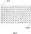
- FIG. 2 shows a raw 13x9 pixel image of a portion of a block of butter that contains a small contaminant (a 0.9mm stainless steel fragment).
- a pure white (255) line has been added on the left of the image (column 1) in order to demonstrate how the apparatus of the present invention avoids edge detection.
- the contaminant pixels (10,5) and (10,6) in the image) has been highlighted.
- the settings for the algorithm in this example are:
- Table 1 is populated with the grey values of the pixels in Figure 2 .
- the columns and rows of table 1 represent the columns and rows of the pixels within Figure 2 .
- the first column of pixels in Figure 2 is white, representing a portion of the image falling off the butter (an edge of the butter), and the grey values of each of these pixels is 255 accordingly, as shown in table 1.
- Pixels (10, 5) and (10,6) within Figure 2 represent the contaminant and these have corresponding low grey values of 51 and 57, as also shown in table 1.
- Table 2 is populated with the scores obtained by processing each pixel in Figure 2 using the algorithm, with the settings described above, including a threshold value of 35.
- the scores in table 2 the pixels in the first column that represent the edge have not given rise to false triggering, since the scores in respect of the pixels adjacent to the first column all fall below the threshold of 35, whilst the contaminant has been detected, since the scores of the pixels, (10, 5) and (10,6), representing the contaminant are the only scores that exceed the threshold of 35.
- the contaminant is two pixels high in the vertical direction and spans pixels (10,5) and (10,6).
- pixels (10,5) since the maximum particle size is set at two pixels, its immediately adjacent pixels, pixels (10,4) and (10,6) are not selected as neighbours. Were they to be selected then pixel (10,6) which has the lowest grey value (since the contaminant spans this pixel) would be compared to pixel (10,5), which would give rise to a low difference value and resulting score and would prevent detection of the contaminant in the vertical direction.
- pixels (10,3) and (10,7) are selected as neighbours, by virtue of the user defined maximum particle setting, and the contaminant does not span these particles, there is a large difference value and the contaminant is detected in the vertical direction.
- the present invention provides an X-ray imaging apparatus that is effective in locating contaminants within an article whilst avoiding false triggering as a result of edge detection or similar.
- the algorithm may be applied to any alternative greyscale image, for example a 16-bit greyscale image having grey values from 0 to 65535.
- the algorithm could be extended to 24-bit colour images by considering each red, green and blue component as a separate 8-bit bitmap.
Landscapes
- Engineering & Computer Science (AREA)
- Physics & Mathematics (AREA)
- General Physics & Mathematics (AREA)
- Chemical & Material Sciences (AREA)
- Biochemistry (AREA)
- Theoretical Computer Science (AREA)
- Health & Medical Sciences (AREA)
- Life Sciences & Earth Sciences (AREA)
- Quality & Reliability (AREA)
- Analytical Chemistry (AREA)
- Computer Vision & Pattern Recognition (AREA)
- General Health & Medical Sciences (AREA)
- Immunology (AREA)
- Pathology (AREA)
- Analysing Materials By The Use Of Radiation (AREA)
- Image Processing (AREA)
- Apparatus For Radiation Diagnosis (AREA)
- Image Analysis (AREA)
Claims (14)
- Appareil d'inspection par rayons X permettant de localiser un contaminant dans un produit (5), l'appareil comprenant :un moyen de génération d'une image par rayons X du produit ;un moyen d'affectation d'une valeur d'échelle de gris à une pluralité de pixels de ladite image ; caractérisé en ce qu'il comprend en outre :un moyen d'identification d'une pluralité de pixels suspects ;un moyen adapté pour, pour chaque pixel suspect :sélectionner deux pixels voisins dans une première direction se situant sur des côtés opposés du pixel suspect et déterminer lequel des pixels de la première direction a la plus faible valeur de gris ;sélectionner deux pixels voisins dans une seconde direction se situant sur des côtés opposés du pixel suspect et déterminer lequel des pixels de la seconde direction a la plus faible valeur de gris ;déterminer une valeur de différence de première direction en prenant la différence de valeur de gris entre le pixel de première direction de valeur de gris la plus faible et la valeur de gris du suspect ;déterminer une valeur de différence de seconde direction en prenant la différence de valeur de gris entre le pixel de seconde direction de valeur de gris la plus faible et la valeur de gris du suspect ;pondérer la valeur de différence de première direction en dépendance de la valeur de gris du pixel de première direction de valeur de gris la plus faible ;pondérer la valeur de différence de seconde direction en dépendance de la valeur de gris du pixel de seconde direction de valeur de gris la plus faible ;déterminer un score de première direction à partir de la valeur de différence de première direction pondérée;déterminer un score de seconde direction à partir de la valeur de différence de seconde direction pondérée ;comparer lesdits scores à une valeur seuil ; etidentifier le pixel suspect comme représentant un contaminant si ladite valeur seuil est dépassée.
- Appareil selon la revendication 1, dans lequel ladite pondération est réalisée en conformité avec l'équation :

- Appareil selon la revendication 1 ou 2, dans lequel les scores sont individuellement comparés audit seuil.
- Appareil selon la revendication 3, dans lequel le pixel suspect est identifié comme représentant un contaminant si un score dépasse la valeur seuil, ou le pixel suspect est identifié comme représentant un contaminant si chaque score dépasse la valeur seuil, ou le pixel suspect est identifié comme représentant un contaminant si la moyenne des scores dépasse la valeur seuil.
- Appareil selon l'une quelconque des revendications précédentes, dans lequel un pixel est identifié comme un pixel suspect s'il a une valeur de gris qui est inférieure à une valeur prédéterminée.
- Appareil selon l'une quelconque des revendications précédentes, dans lequel la première direction est orthogonale à la seconde direction.
- Appareil selon l'une quelconque des revendications précédentes, comprenant un moyen d'établissement d'une distance entre chacun des pixels voisins et le pixel suspect, en dépendance d'une taille de contaminant maximale définie par utilisateur, dans lequel chaque pixel voisin est espacé du pixel suspect d'une distance telle qu'un contaminant de la taille maximale ne puisse pas enjamber le pixel suspect et l'un des pixels voisins.
- Procédé d'inspection par rayons X implémenté par ordinateur destiné à localiser un contaminant dans un produit (5), le procédé comprenant les étapes de :génération d'une image par rayons X du produit ;affectation d'une valeur d'échelle de gris à une pluralité de pixels de ladite image ;identification d'une pluralité de pixels suspects ;sélection de deux pixels voisins dans une première direction se situant sur des côtés opposés d'un pixel suspect et fait de déterminer lequel des pixels de la première direction a la plus faible valeur de gris ;sélection de deux pixels voisins dans une seconde direction se situant sur des côtés opposés du pixel suspect sélectionné et fait de déterminer lequel des pixels de la seconde direction a la plus faible valeur de gris ;détermination d'une valeur de différence de première direction en prenant la différence de valeur de gris entre le pixel de première direction de valeur de gris la plus faible et la valeur de gris du suspect ;détermination d'une valeur de différence de seconde direction en prenant la différence de valeur de gris entre le pixel de seconde direction de valeur de gris la plus faible et la valeur de gris du suspect ;pondération de la valeur de différence de première direction en dépendance de la valeur de gris du pixel de première direction de valeur de gris la plus faible ; pondération de la valeur de différence de seconde direction en dépendance de la valeur de gris du pixel de seconde direction de valeur de gris la plus faible ; détermination d'un score de première direction à partir de la valeur de différence de première direction pondérée; détermination d'un score de seconde direction à partir de la valeur de différence de seconde direction pondérée ;comparaison desdits scores avec une valeur seuil ;identification du pixel suspect comme représentant un contaminant si ladite valeur seuil est dépassée.
- Procédé selon la revendication 8, dans lequel ladite pondération est réalisée en conformité avec l'équation :

- Procédé selon la revendication 8 ou 9, dans lequel les scores sont individuellement comparés audit seuil.
- Procédé selon la revendication 10, dans lequel le pixel suspect est identifié comme représentant un contaminant si un score dépasse la valeur seuil, ou le pixel suspect est identifié comme représentant un contaminant si chaque score dépasse la valeur seuil, ou le pixel suspect est identifié comme représentant un contaminant si la moyenne des scores dépasse la valeur seuil.
- Procédé selon l'une quelconque des revendications 8 à 11, dans lequel un pixel est identifié comme un pixel suspect s'il a une valeur de gris qui est inférieure à une valeur prédéterminée.
- Procédé selon l'une quelconque des revendications 8 à 12, dans lequel la première direction est orthogonale à la seconde direction.
- Procédé selon l'une quelconque des revendications 8 à 13, comprenant l'étape d'établissement d'une distance entre chacun des pixels voisins et le pixel suspect, en dépendance d'une taille de contaminant maximale définie par utilisateur, dans lequel chaque pixel voisin est espacé du pixel suspect d'une distance telle qu'un contaminant de la taille maximale ne puisse pas enjamber le pixel suspect et l'un des pixels voisins.
Applications Claiming Priority (2)
| Application Number | Priority Date | Filing Date | Title |
|---|---|---|---|
| GB0709183A GB2449239B (en) | 2007-05-14 | 2007-05-14 | X-ray imaging |
| PCT/IB2008/001190 WO2008139316A2 (fr) | 2007-05-14 | 2008-05-13 | Imagerie à rayons x |
Publications (2)
| Publication Number | Publication Date |
|---|---|
| EP2156406A2 EP2156406A2 (fr) | 2010-02-24 |
| EP2156406B1 true EP2156406B1 (fr) | 2017-10-25 |
Family
ID=38219319
Family Applications (1)
| Application Number | Title | Priority Date | Filing Date |
|---|---|---|---|
| EP08750931.1A Not-in-force EP2156406B1 (fr) | 2007-05-14 | 2008-05-13 | Détection de corps etrangers utilisant la imagerie à rayons x |
Country Status (7)
| Country | Link |
|---|---|
| US (1) | US8712107B2 (fr) |
| EP (1) | EP2156406B1 (fr) |
| CN (1) | CN101675457B (fr) |
| CA (1) | CA2683577A1 (fr) |
| GB (1) | GB2449239B (fr) |
| TW (1) | TW200905190A (fr) |
| WO (1) | WO2008139316A2 (fr) |
Families Citing this family (4)
| Publication number | Priority date | Publication date | Assignee | Title |
|---|---|---|---|---|
| US8457366B2 (en) | 2008-12-12 | 2013-06-04 | At&T Intellectual Property I, L.P. | System and method for matching faces |
| JP5864404B2 (ja) * | 2012-12-07 | 2016-02-17 | 株式会社イシダ | X線検査装置 |
| WO2017003665A1 (fr) * | 2015-06-30 | 2017-01-05 | Illinois Tool Works Inc. | Appareil et procédé de mesure à rayons x en ligne |
| US11386642B2 (en) * | 2020-10-12 | 2022-07-12 | Home Box Office, Inc. | Image difference detection |
Family Cites Families (11)
| Publication number | Priority date | Publication date | Assignee | Title |
|---|---|---|---|---|
| US5774573A (en) * | 1984-12-20 | 1998-06-30 | Orbotech Ltd. | Automatic visual inspection system |
| US5365596A (en) | 1992-12-17 | 1994-11-15 | Philip Morris Incorporated | Methods and apparatus for automatic image inspection of continuously moving objects |
| JPH08145904A (ja) | 1994-11-15 | 1996-06-07 | Toshiba Eng Co Ltd | 明欠陥/暗欠陥検査装置 |
| JP3310677B2 (ja) * | 1996-09-12 | 2002-08-05 | アンリツ株式会社 | 選択性の高い画像処理による高感度な異物検出装置 |
| US6687395B1 (en) | 1999-07-21 | 2004-02-03 | Surromed, Inc. | System for microvolume laser scanning cytometry |
| US6914611B2 (en) * | 2000-07-07 | 2005-07-05 | Koninklijke Philips Electronics N.V. | Window detection |
| JP3526263B2 (ja) | 2000-09-08 | 2004-05-10 | 株式会社イシダ | X線異物検査装置 |
| WO2005008223A2 (fr) | 2003-07-18 | 2005-01-27 | Applied Materials Israel, Ltd. | Procedes de detection de defauts et de surveillance de traitement base sur des images de microscope electronique a balayage (sem) |
| CN100472206C (zh) | 2004-09-15 | 2009-03-25 | 中国农业大学 | 食品中异物的检测方法 |
| US7190819B2 (en) * | 2004-10-29 | 2007-03-13 | Stereotaxis, Inc. | Image-based medical device localization |
| US8264526B2 (en) * | 2008-06-27 | 2012-09-11 | The University Of Southern Mississippi | Method for front matching stereo vision |
-
2007
- 2007-05-14 GB GB0709183A patent/GB2449239B/en not_active Expired - Fee Related
-
2008
- 2008-05-09 TW TW097117262A patent/TW200905190A/zh unknown
- 2008-05-13 WO PCT/IB2008/001190 patent/WO2008139316A2/fr not_active Ceased
- 2008-05-13 US US12/600,247 patent/US8712107B2/en active Active
- 2008-05-13 CA CA002683577A patent/CA2683577A1/fr not_active Abandoned
- 2008-05-13 CN CN2008800148478A patent/CN101675457B/zh not_active Expired - Fee Related
- 2008-05-13 EP EP08750931.1A patent/EP2156406B1/fr not_active Not-in-force
Non-Patent Citations (1)
| Title |
|---|
| None * |
Also Published As
| Publication number | Publication date |
|---|---|
| CN101675457A (zh) | 2010-03-17 |
| GB2449239A (en) | 2008-11-19 |
| CA2683577A1 (fr) | 2008-11-20 |
| WO2008139316A2 (fr) | 2008-11-20 |
| WO2008139316A3 (fr) | 2009-08-13 |
| CN101675457B (zh) | 2012-05-30 |
| US8712107B2 (en) | 2014-04-29 |
| GB0709183D0 (en) | 2007-06-20 |
| US20100303304A1 (en) | 2010-12-02 |
| EP2156406A2 (fr) | 2010-02-24 |
| GB2449239B (en) | 2009-11-04 |
| TW200905190A (en) | 2009-02-01 |
Similar Documents
| Publication | Publication Date | Title |
|---|---|---|
| US5828725A (en) | Processing images for removal of artifacts | |
| EP1767927B1 (fr) | Dispositif d'inspection aux rayons x, et méthode pour créer un procédé de traitement d'images pour le dispositif d'inspection aux rayons x | |
| US6023497A (en) | Apparatus for detecting foreign matter with high selectivity and high sensitivity by image processing | |
| EP0574831B1 (fr) | Appareil de contrÔle de produits | |
| EP2156406B1 (fr) | Détection de corps etrangers utilisant la imagerie à rayons x | |
| US20100246930A1 (en) | Inspection apparatus and method using penetrating radiation | |
| JPWO1998011456A1 (ja) | 選択性の高い画像処理による高感度な異物検出装置 | |
| CN115880241B (zh) | 一种红外图像盲元的检测处理方法及系统 | |
| US11598729B2 (en) | X-ray inspection device | |
| JP2007017163A (ja) | 粒状製品の評価方法 | |
| JP5243008B2 (ja) | X線異物検出装置 | |
| JP4574478B2 (ja) | X線異物検出方法及びx線異物検出装置 | |
| JP2024160948A (ja) | 製品の二次元のデジタル画像で異常を検出する方法および装置 | |
| JP5864404B2 (ja) | X線検査装置 | |
| JP2016156647A (ja) | 電磁波を使用した検査装置 | |
| JP2005031069A (ja) | X線検査装置 | |
| JPH10208046A (ja) | X線異物検出方法 | |
| JP5875878B2 (ja) | 密度算出装置 | |
| JP2025144156A (ja) | X線検査装置 | |
| CN114140456B (zh) | 一种基于图像识别的智能食品检测方法及系统 | |
| As et al. | Identification and classification of the quality of snake fruit using image processing techniques: A computer vision approach | |
| JP6306352B2 (ja) | X線検査装置 | |
| JPWO2010070755A1 (ja) | Tftアレイ検査方法およびtftアレイ検査装置 | |
| JP6774895B2 (ja) | X線検査装置 | |
| JP6901294B2 (ja) | X線検査装置 |
Legal Events
| Date | Code | Title | Description |
|---|---|---|---|
| PUAI | Public reference made under article 153(3) epc to a published international application that has entered the european phase |
Free format text: ORIGINAL CODE: 0009012 |
|
| 17P | Request for examination filed |
Effective date: 20091207 |
|
| AK | Designated contracting states |
Kind code of ref document: A2 Designated state(s): AT BE BG CH CY CZ DE DK EE ES FI FR GB GR HR HU IE IS IT LI LT LU LV MC MT NL NO PL PT RO SE SI SK TR |
|
| AX | Request for extension of the european patent |
Extension state: AL BA MK RS |
|
| DAX | Request for extension of the european patent (deleted) | ||
| RAP1 | Party data changed (applicant data changed or rights of an application transferred) |
Owner name: ILLINOIS TOOL WORKS INC. |
|
| 17Q | First examination report despatched |
Effective date: 20140707 |
|
| GRAP | Despatch of communication of intention to grant a patent |
Free format text: ORIGINAL CODE: EPIDOSNIGR1 |
|
| RIC1 | Information provided on ipc code assigned before grant |
Ipc: G06T 7/00 20060101AFI20160822BHEP Ipc: G01N 23/04 20060101ALI20160822BHEP |
|
| INTG | Intention to grant announced |
Effective date: 20160915 |
|
| GRAJ | Information related to disapproval of communication of intention to grant by the applicant or resumption of examination proceedings by the epo deleted |
Free format text: ORIGINAL CODE: EPIDOSDIGR1 |
|
| STAA | Information on the status of an ep patent application or granted ep patent |
Free format text: STATUS: EXAMINATION IS IN PROGRESS |
|
| INTC | Intention to grant announced (deleted) | ||
| GRAP | Despatch of communication of intention to grant a patent |
Free format text: ORIGINAL CODE: EPIDOSNIGR1 |
|
| STAA | Information on the status of an ep patent application or granted ep patent |
Free format text: STATUS: GRANT OF PATENT IS INTENDED |
|
| INTG | Intention to grant announced |
Effective date: 20170323 |
|
| GRAS | Grant fee paid |
Free format text: ORIGINAL CODE: EPIDOSNIGR3 |
|
| GRAJ | Information related to disapproval of communication of intention to grant by the applicant or resumption of examination proceedings by the epo deleted |
Free format text: ORIGINAL CODE: EPIDOSDIGR1 |
|
| GRAL | Information related to payment of fee for publishing/printing deleted |
Free format text: ORIGINAL CODE: EPIDOSDIGR3 |
|
| STAA | Information on the status of an ep patent application or granted ep patent |
Free format text: STATUS: EXAMINATION IS IN PROGRESS |
|
| INTC | Intention to grant announced (deleted) | ||
| GRAR | Information related to intention to grant a patent recorded |
Free format text: ORIGINAL CODE: EPIDOSNIGR71 |
|
| STAA | Information on the status of an ep patent application or granted ep patent |
Free format text: STATUS: GRANT OF PATENT IS INTENDED |
|
| GRAA | (expected) grant |
Free format text: ORIGINAL CODE: 0009210 |
|
| STAA | Information on the status of an ep patent application or granted ep patent |
Free format text: STATUS: THE PATENT HAS BEEN GRANTED |
|
| AK | Designated contracting states |
Kind code of ref document: B1 Designated state(s): AT BE BG CH CY CZ DE DK EE ES FI FR GB GR HR HU IE IS IT LI LT LU LV MC MT NL NO PL PT RO SE SI SK TR |
|
| INTG | Intention to grant announced |
Effective date: 20170918 |
|
| REG | Reference to a national code |
Ref country code: GB Ref legal event code: FG4D |
|
| REG | Reference to a national code |
Ref country code: CH Ref legal event code: EP |
|
| REG | Reference to a national code |
Ref country code: AT Ref legal event code: REF Ref document number: 940565 Country of ref document: AT Kind code of ref document: T Effective date: 20171115 |
|
| REG | Reference to a national code |
Ref country code: IE Ref legal event code: FG4D |
|
| REG | Reference to a national code |
Ref country code: DE Ref legal event code: R096 Ref document number: 602008052652 Country of ref document: DE |
|
| REG | Reference to a national code |
Ref country code: NL Ref legal event code: MP Effective date: 20171025 |
|
| REG | Reference to a national code |
Ref country code: LT Ref legal event code: MG4D |
|
| REG | Reference to a national code |
Ref country code: AT Ref legal event code: MK05 Ref document number: 940565 Country of ref document: AT Kind code of ref document: T Effective date: 20171025 |
|
| PG25 | Lapsed in a contracting state [announced via postgrant information from national office to epo] |
Ref country code: NL Free format text: LAPSE BECAUSE OF FAILURE TO SUBMIT A TRANSLATION OF THE DESCRIPTION OR TO PAY THE FEE WITHIN THE PRESCRIBED TIME-LIMIT Effective date: 20171025 |
|
| PG25 | Lapsed in a contracting state [announced via postgrant information from national office to epo] |
Ref country code: SE Free format text: LAPSE BECAUSE OF FAILURE TO SUBMIT A TRANSLATION OF THE DESCRIPTION OR TO PAY THE FEE WITHIN THE PRESCRIBED TIME-LIMIT Effective date: 20171025 Ref country code: NO Free format text: LAPSE BECAUSE OF FAILURE TO SUBMIT A TRANSLATION OF THE DESCRIPTION OR TO PAY THE FEE WITHIN THE PRESCRIBED TIME-LIMIT Effective date: 20180125 Ref country code: ES Free format text: LAPSE BECAUSE OF FAILURE TO SUBMIT A TRANSLATION OF THE DESCRIPTION OR TO PAY THE FEE WITHIN THE PRESCRIBED TIME-LIMIT Effective date: 20171025 Ref country code: FI Free format text: LAPSE BECAUSE OF FAILURE TO SUBMIT A TRANSLATION OF THE DESCRIPTION OR TO PAY THE FEE WITHIN THE PRESCRIBED TIME-LIMIT Effective date: 20171025 Ref country code: LT Free format text: LAPSE BECAUSE OF FAILURE TO SUBMIT A TRANSLATION OF THE DESCRIPTION OR TO PAY THE FEE WITHIN THE PRESCRIBED TIME-LIMIT Effective date: 20171025 |
|
| PG25 | Lapsed in a contracting state [announced via postgrant information from national office to epo] |
Ref country code: BG Free format text: LAPSE BECAUSE OF FAILURE TO SUBMIT A TRANSLATION OF THE DESCRIPTION OR TO PAY THE FEE WITHIN THE PRESCRIBED TIME-LIMIT Effective date: 20180125 Ref country code: LV Free format text: LAPSE BECAUSE OF FAILURE TO SUBMIT A TRANSLATION OF THE DESCRIPTION OR TO PAY THE FEE WITHIN THE PRESCRIBED TIME-LIMIT Effective date: 20171025 Ref country code: GR Free format text: LAPSE BECAUSE OF FAILURE TO SUBMIT A TRANSLATION OF THE DESCRIPTION OR TO PAY THE FEE WITHIN THE PRESCRIBED TIME-LIMIT Effective date: 20180126 Ref country code: IS Free format text: LAPSE BECAUSE OF FAILURE TO SUBMIT A TRANSLATION OF THE DESCRIPTION OR TO PAY THE FEE WITHIN THE PRESCRIBED TIME-LIMIT Effective date: 20180225 Ref country code: AT Free format text: LAPSE BECAUSE OF FAILURE TO SUBMIT A TRANSLATION OF THE DESCRIPTION OR TO PAY THE FEE WITHIN THE PRESCRIBED TIME-LIMIT Effective date: 20171025 Ref country code: HR Free format text: LAPSE BECAUSE OF FAILURE TO SUBMIT A TRANSLATION OF THE DESCRIPTION OR TO PAY THE FEE WITHIN THE PRESCRIBED TIME-LIMIT Effective date: 20171025 |
|
| REG | Reference to a national code |
Ref country code: DE Ref legal event code: R097 Ref document number: 602008052652 Country of ref document: DE |
|
| PG25 | Lapsed in a contracting state [announced via postgrant information from national office to epo] |
Ref country code: CZ Free format text: LAPSE BECAUSE OF FAILURE TO SUBMIT A TRANSLATION OF THE DESCRIPTION OR TO PAY THE FEE WITHIN THE PRESCRIBED TIME-LIMIT Effective date: 20171025 Ref country code: CY Free format text: LAPSE BECAUSE OF FAILURE TO SUBMIT A TRANSLATION OF THE DESCRIPTION OR TO PAY THE FEE WITHIN THE PRESCRIBED TIME-LIMIT Effective date: 20171025 Ref country code: EE Free format text: LAPSE BECAUSE OF FAILURE TO SUBMIT A TRANSLATION OF THE DESCRIPTION OR TO PAY THE FEE WITHIN THE PRESCRIBED TIME-LIMIT Effective date: 20171025 Ref country code: DK Free format text: LAPSE BECAUSE OF FAILURE TO SUBMIT A TRANSLATION OF THE DESCRIPTION OR TO PAY THE FEE WITHIN THE PRESCRIBED TIME-LIMIT Effective date: 20171025 Ref country code: SK Free format text: LAPSE BECAUSE OF FAILURE TO SUBMIT A TRANSLATION OF THE DESCRIPTION OR TO PAY THE FEE WITHIN THE PRESCRIBED TIME-LIMIT Effective date: 20171025 |
|
| PG25 | Lapsed in a contracting state [announced via postgrant information from national office to epo] |
Ref country code: IT Free format text: LAPSE BECAUSE OF FAILURE TO SUBMIT A TRANSLATION OF THE DESCRIPTION OR TO PAY THE FEE WITHIN THE PRESCRIBED TIME-LIMIT Effective date: 20171025 Ref country code: RO Free format text: LAPSE BECAUSE OF FAILURE TO SUBMIT A TRANSLATION OF THE DESCRIPTION OR TO PAY THE FEE WITHIN THE PRESCRIBED TIME-LIMIT Effective date: 20171025 Ref country code: PL Free format text: LAPSE BECAUSE OF FAILURE TO SUBMIT A TRANSLATION OF THE DESCRIPTION OR TO PAY THE FEE WITHIN THE PRESCRIBED TIME-LIMIT Effective date: 20171025 |
|
| PLBE | No opposition filed within time limit |
Free format text: ORIGINAL CODE: 0009261 |
|
| STAA | Information on the status of an ep patent application or granted ep patent |
Free format text: STATUS: NO OPPOSITION FILED WITHIN TIME LIMIT |
|
| 26N | No opposition filed |
Effective date: 20180726 |
|
| PG25 | Lapsed in a contracting state [announced via postgrant information from national office to epo] |
Ref country code: SI Free format text: LAPSE BECAUSE OF FAILURE TO SUBMIT A TRANSLATION OF THE DESCRIPTION OR TO PAY THE FEE WITHIN THE PRESCRIBED TIME-LIMIT Effective date: 20171025 |
|
| REG | Reference to a national code |
Ref country code: DE Ref legal event code: R119 Ref document number: 602008052652 Country of ref document: DE |
|
| REG | Reference to a national code |
Ref country code: CH Ref legal event code: PL |
|
| GBPC | Gb: european patent ceased through non-payment of renewal fee |
Effective date: 20180513 |
|
| REG | Reference to a national code |
Ref country code: BE Ref legal event code: MM Effective date: 20180531 |
|
| PG25 | Lapsed in a contracting state [announced via postgrant information from national office to epo] |
Ref country code: MC Free format text: LAPSE BECAUSE OF FAILURE TO SUBMIT A TRANSLATION OF THE DESCRIPTION OR TO PAY THE FEE WITHIN THE PRESCRIBED TIME-LIMIT Effective date: 20171025 |
|
| REG | Reference to a national code |
Ref country code: IE Ref legal event code: MM4A |
|
| PG25 | Lapsed in a contracting state [announced via postgrant information from national office to epo] |
Ref country code: CH Free format text: LAPSE BECAUSE OF NON-PAYMENT OF DUE FEES Effective date: 20180531 Ref country code: LI Free format text: LAPSE BECAUSE OF NON-PAYMENT OF DUE FEES Effective date: 20180531 |
|
| PG25 | Lapsed in a contracting state [announced via postgrant information from national office to epo] |
Ref country code: LU Free format text: LAPSE BECAUSE OF NON-PAYMENT OF DUE FEES Effective date: 20180513 |
|
| PG25 | Lapsed in a contracting state [announced via postgrant information from national office to epo] |
Ref country code: IE Free format text: LAPSE BECAUSE OF NON-PAYMENT OF DUE FEES Effective date: 20180513 Ref country code: DE Free format text: LAPSE BECAUSE OF NON-PAYMENT OF DUE FEES Effective date: 20181201 Ref country code: GB Free format text: LAPSE BECAUSE OF NON-PAYMENT OF DUE FEES Effective date: 20180513 Ref country code: FR Free format text: LAPSE BECAUSE OF NON-PAYMENT OF DUE FEES Effective date: 20180531 |
|
| PG25 | Lapsed in a contracting state [announced via postgrant information from national office to epo] |
Ref country code: BE Free format text: LAPSE BECAUSE OF NON-PAYMENT OF DUE FEES Effective date: 20180531 |
|
| PG25 | Lapsed in a contracting state [announced via postgrant information from national office to epo] |
Ref country code: MT Free format text: LAPSE BECAUSE OF NON-PAYMENT OF DUE FEES Effective date: 20180513 |
|
| PG25 | Lapsed in a contracting state [announced via postgrant information from national office to epo] |
Ref country code: TR Free format text: LAPSE BECAUSE OF FAILURE TO SUBMIT A TRANSLATION OF THE DESCRIPTION OR TO PAY THE FEE WITHIN THE PRESCRIBED TIME-LIMIT Effective date: 20171025 |
|
| PG25 | Lapsed in a contracting state [announced via postgrant information from national office to epo] |
Ref country code: HU Free format text: LAPSE BECAUSE OF FAILURE TO SUBMIT A TRANSLATION OF THE DESCRIPTION OR TO PAY THE FEE WITHIN THE PRESCRIBED TIME-LIMIT; INVALID AB INITIO Effective date: 20080513 Ref country code: PT Free format text: LAPSE BECAUSE OF FAILURE TO SUBMIT A TRANSLATION OF THE DESCRIPTION OR TO PAY THE FEE WITHIN THE PRESCRIBED TIME-LIMIT Effective date: 20171025 |