EP2156592B1 - Réponse à otuk-bdi pour interfaces otn en vue de restaurer des communications bidirectionnelles - Google Patents
Réponse à otuk-bdi pour interfaces otn en vue de restaurer des communications bidirectionnelles Download PDFInfo
- Publication number
- EP2156592B1 EP2156592B1 EP08769868.4A EP08769868A EP2156592B1 EP 2156592 B1 EP2156592 B1 EP 2156592B1 EP 08769868 A EP08769868 A EP 08769868A EP 2156592 B1 EP2156592 B1 EP 2156592B1
- Authority
- EP
- European Patent Office
- Prior art keywords
- network element
- otn
- signal
- bdi
- unidirectional
- Prior art date
- Legal status (The legal status is an assumption and is not a legal conclusion. Google has not performed a legal analysis and makes no representation as to the accuracy of the status listed.)
- Not-in-force
Links
Images
Classifications
-
- H—ELECTRICITY
- H04—ELECTRIC COMMUNICATION TECHNIQUE
- H04J—MULTIPLEX COMMUNICATION
- H04J14/00—Optical multiplex systems
- H04J14/02—Wavelength-division multiplex systems
- H04J14/0287—Protection in WDM systems
- H04J14/0293—Optical channel protection
-
- H—ELECTRICITY
- H04—ELECTRIC COMMUNICATION TECHNIQUE
- H04J—MULTIPLEX COMMUNICATION
- H04J14/00—Optical multiplex systems
- H04J14/02—Wavelength-division multiplex systems
- H04J14/0278—WDM optical network architectures
- H04J14/0283—WDM ring architectures
-
- H—ELECTRICITY
- H04—ELECTRIC COMMUNICATION TECHNIQUE
- H04J—MULTIPLEX COMMUNICATION
- H04J14/00—Optical multiplex systems
- H04J14/02—Wavelength-division multiplex systems
- H04J14/0278—WDM optical network architectures
- H04J14/0284—WDM mesh architectures
-
- H—ELECTRICITY
- H04—ELECTRIC COMMUNICATION TECHNIQUE
- H04J—MULTIPLEX COMMUNICATION
- H04J3/00—Time-division multiplex systems
- H04J3/02—Details
- H04J3/14—Monitoring arrangements
-
- H—ELECTRICITY
- H04—ELECTRIC COMMUNICATION TECHNIQUE
- H04J—MULTIPLEX COMMUNICATION
- H04J2203/00—Aspects of optical multiplex systems other than those covered by H04J14/05 and H04J14/07
- H04J2203/0001—Provisions for broadband connections in integrated services digital network using frames of the Optical Transport Network [OTN] or using synchronous transfer mode [STM], e.g. SONET, SDH
- H04J2203/0057—Operations, administration and maintenance [OAM]
- H04J2203/006—Fault tolerance and recovery
Definitions
- the present invention is generally related to techniques of ensuring bidirectional notification of a unidirectional failure in an optical network and, more specifically, to ensuring protection switching in both directions upon a unidirectional failure in an OTN (Optical Transport Network).
- OTN Optical Transport Network
- optical networks had been confined mostly to the so-called long-haul telephone networks which were based upon SONET/SDH technology.
- the rise of the Internet increased the demand upon these optical networks which were based on less demanding telephonic requirements.
- IP Internet Packet
- protocols were developed for the IP packets to be transported by the SONET/SDH networks, sometimes characterized as POS (Packets over SONET).
- POS Packets over SONET
- VoIP voice over IP
- IPTV IP-based television
- VoD high-definition video-on-demand
- POS Packet over SONET
- OTN Optical Transport Network
- ITU-T the Telecommunications Standardization Sector of the International Telecommunications Union
- OAM&P Operations, Administration, Management and Provisioning
- EP 1737145 discloses a method for meshwork restoration, which includes the steps of: a) reserving channel resource for restoration path in the link by which the path passes and assigning identifier for each channel, and determining the associated signaling channels in which the said identifier is conveyed; b) when detecting the said work path failure, activating the restoration path of the said work path according to the identifier which is conveyed by the associated signaling channel and whose value is identifying restoration.
- EP 1531566 discloses a method for enhancing a trail/path protection function in a SDH/SONET network, the network comprising a number of working resources and a number of protection resources and transmitting signal frames having a section overhead in SDH technology, or a Line OverHead in SONET technology, and a POH, the protection function comprising linear MSP N:1 trail protection function based on transmission of protection information through K1 and K2 bytes of Section OverHead in SDH or Line OverHead in SONET.
- OTN does not necessarily provide a seamless fit for transporting IP data over a transport network.
- the present invention addresses this problem so that switching can be performed bidirectionally to protect the communications on the optical network.
- the OTN interface apparatus comprises at least one integrated circuit having circuits adapted to generate an alarm indication signal for the first network element upon receiving a BDI signal from a remote network element so that the first network element switches routing to the remote network element in response.
- Another aspect provides for a method of operating an OTN.
- the method comprises: sending a plurality of OTN frames from a first network element to a second network element; detecting a failure in the sending step; switching routing from second network element to the first network element in response to the failure detecting step and sending a BDI signal from the second network element to the first network element; and generating an alarm indication signal for the first network element so that the first network element switches routing from the first network element to the second network element in response; whereby the routing switching is performed bidirectionally.
- Still another aspect provides for an OTN interface apparatus for a first network element in an optical network.
- the OTN interface apparatus comprises: means for sending a plurality of OTN frames to a remote network element; means for receiving a BDI signal from the remote network element in response to a transmission failure of the plurality of OTN frames to the remote network element; and means for generating an alarm indication signal for the first network element so that the first network element switches routing to the remote network element in response.
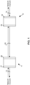
- Fig. 1 illustrates an example pair of network elements 11 and 12, such as client access points or 3R (Regeneration, Reshape and Re-time) points, of a representative OTN.
- the network elements 11 and 12 are connected by bidirectional communication channels 10 and are shown as being connected to another network element by bidirectional communication channels 13 and 14 respectively.
- the channels 10, 13 and 14 are carried by one or more optical fibers.
- the Fig. 1 network might be considered part of a ring network, the relatively simple arrangement is selected for the purposes of ease of illustration and the network of Fig. 1 should not be considered so limited. More networks, such as mesh networks, can likewise be contemplated.
- the network element 11 has a port 20 which is connected to the bidirectional communication channels 10 and a port 21 to the bidirectional communication channels 13.
- the network element 12 port 23 which is connected to the bidirectional communication channels 20 and a port 22 which is connected to the bidirectional communication channels 14.
- the two network elements 11 and 12 with respective OTN interfaces 20 and 23 of Fig. 1 parts of an OTN, communicate over a communications channel 10A from the node 11 to the network element 12 and over a communications channel 10B from the network element 12 to the network element 11. Together both channels 10A and 10B form the bidirectional communication channels 10.
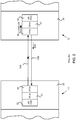
- Fig. 2 represents the encapsulation of client data 32 in an ODU (Optical Data Unit) layer 31 and then in an OTU (Optical Transport Unit) layer 30 for transport in an OTN frame from network element 11 to network element 12.
- the client data 32 are decapsulated from the OTU and ODU layers 30 and 31.
- the client data 32 are transported directly and in this example are Gigabit Ethernet or 10 Gigabit Ethernet data which, it should be noted, has increasingly become the protocol of choice of IP traffic.
- the client data 32 is native, to be distinguished from Ethernet data first encapsulated into SONET/SDH frames according to the older POS procedure.
- the network element 12 When a failure on one of the communications channels occurs, as represented in this example by the "X" on the unidirectional communications channel 10A, the network element 12 which is receiving the transported data determines the failure occurrence and issues an AIS (Alarm Indication Signal), such as an LOS (Loss of Signal) and LOF (Loss of Frame). From these signals the interface 21 shuts down and switches to another communications channel for protection. Also, the network element 12 through the port 23 injects an OTUk-BDI (Backward Defect Indication) signal back toward the network element 11.
- the BDI signal which is an OTN maintenance signal, is asserted in the OTU frames being sent back from the network element 12 to the network element 11.
- the port 20 and the network element 11 detect the BDI signal and notifies the network management. No protection switching to route around the failure is performed.
- the detection of a maintenance OTN signal, the OTUk-BDI does not generate any action in the network element 11 and the port 20.
- the OTN standards specifically ITU-T G. 798, do not require any action for the OTUk-BDI signal toward the client interface. The net result is that the protection switching is unidirectional, i.e., the communications channel 10B is rerouted, but not the communications channel 10A.
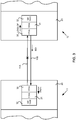
- Fig. 3 illustrates an embodiment of the present invention.
- the port for the sending network element i.e., the port 20 and network element 11 in this example, generates an AIS (Alarm Indicator Signal) for the network element 11.
- the AIS is preferably a PN-11 signal, a 2047-bit polynomial sequence which covers an entire OTU frame including the framing bytes (FAS (Frame Alignment Signals)).
- FAS Framing bytes
- the network element represents an IP router with an OTN interface
- MPLS MultiProtocol Label Switching
- An improved or newer version of MPLS is GMPLS (Generalized MPLS) which is expected to be widely used future optical networks.
- MPLS operates at an OSI (Open Systems Interconnection) Reference Model layer that is generally considered to lie between traditional definitions of Layer 2 (the data link layer) and Layer 3 (the network layer) and provides a unified data-carrying service for both circuit-based clients and packet-switching clients.
- MPLS is used to carry many different kinds of traffic, including IP packets, as well as native ATM (Asynchronous Transfer Mode), SONET, and Ethernet frames.
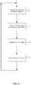
- Fig. 4 illustrates the operations by a flow chart of operations of the OTN frame transmitting network element 11 and its OTN interface 20.
- the dotted line to step 30 indicates that the step 40 is part of continuing operations, including initialization steps, which are not shown.
- the network element transmits OTN frames to the far end network element 12 and its interface 23.
- the network element 12 Upon a failure in the transmission of the OTN frames to the far end network element 12, the network element 12 generates a BDI signal in the OTN frames being sent to the first network element 11 which receives the signal in step 41.
- the interface 20 In response to the BDI signal, the interface 20 generates an AIS, specifically the PN-11 signal for the network element 11 in step 42.
- the network element 11 switches routing to the far end network element 12 and a feedback loop ensures that the OTN frames continue to be sent to the network element 12.
- the network element ports are preferably implemented as line cards, cards for network interfaces.
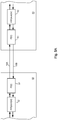
- Fig. 5A illustrates how an example network interface card might be arranged according to one embodiment of the present invention.
- two network interface cards 50 and 53 for the ports 20 and 23 respectively each have one FEC (Forward Error Correction) integrated circuit 51 and one FPGA (Field Programmable Gate Array) integrated circuit 52.
- the integrated circuit 52 can be an ASIC (Application Specific Integrated Circuit). Data is transmitted bidirectionally over the communication channels 10A and 10B (see Fig. 3 ).
- the FEC integrated circuits 51 encode OTN frames by a Reed-Solomon code for transmission and decode them after reception.
- the encoding of the OTN frames helps ensure the integrity of the transmitted data and allows the data to be transmitted successfully at high rates.
- the FPGA/ASIC integrated circuit 52 handles other operations of the port. With respect to the present invention, the FPGA/ASIC 52 generates the AIS, the PN-11 signal, upon reception of the OTUk-BDI signal from the network element to which OTN frames had previously been transmitted. The PN-11 signal then engages the switching mechanisms in the network element so that protection switching is bidirectional.
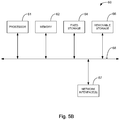
- Fig. 5B illustrates an alternative arrangement for the network interface cards.
- the network interface cards use a generalized arrangement.
- operations and functions of the FPGA/ASIC integrated circuit 52 are carried out by a computer system 60 which includes a memory subsystem 62 which can store and retrieve software programs incorporating computer code that implements aspects of the invention, data for use with the invention, and the like, and a central processor subsystem 61 which, among other functions, processes the instructions and data of the computer code.
- Example computer readable storage media for the memory 62 include semiconductor system memory preferably, CD-ROM, floppy disk, tape, flash memory, and hard drive.
- the computer system 60 further includes subsystems, such as fixed storage 64 (e.g., hard drive), removable storage 66 (e.g., CD-ROM drive), and one or more network interfaces 67, all connected by a system bus 68.
- the network interface 67 might provide the pathway to and from the FEC integrated circuit 51, and to and from the rest of the network interface card (not shown). Additional or fewer subsystems may be used.
- the computer system arrangement 60 may include more than one processor in the subsystem 61 (i.e., a multi-processor system), or a cache memory.
- the computer system 60 arrangement can be used to generate the AIS in response to a received OTUk-BDI signal.
- the computer system 60 could also integrate the functions of the FEC integrated circuit 51, but for most situations the higher speeds of the FEC integrated circuit 51 dedicated to the complex operations of encoding and decoding the Reed-Solomon algorithm of OTN FEC is more suitable.
- OTN optical network
- OAM&P Operations, Administration, Management and Provisioning
Landscapes
- Engineering & Computer Science (AREA)
- Computer Networks & Wireless Communication (AREA)
- Signal Processing (AREA)
- Data Exchanges In Wide-Area Networks (AREA)
Claims (13)
- Procédé de fonctionnement d'une interface OTN pour un premier élément de réseau dans un réseau optique, ledit procédé comprenant :l'envoi (40) de plusieurs trames de réseau de transport optique (OTN) depuis une interface OTN d'un premier élément de réseau à un élément de réseau distant via un premier canal de communication unidirectionnel d'un canal de communication bidirectionnel ;la réception (41) via un deuxième canal unidirectionnel dudit canal de communication bidirectionnel d'un signal indicateur de défaut vers l'arrière (BDI) d'unité de transport optique (OTU) à ladite interface OTN en provenance dudit élément de réseau distant qui est configuré pour indiquer un défaut de transmission dudit premier canal de communication unidirectionnel ; eten réponse à la réception dudit signal OTU BDI, génération (42) d'un signal d'alarme comprenant une séquence polynomiale configurée pour déclencher des opérations de commutation au niveau d'une couche multi-protocol label switching (MPLS) de façon que ledit premier élément de réseau commute l'acheminement audit premier élément de réseau distant.
- Procédé selon la revendication 1, dans lequel générer ledit signal d'alarme comprend de générer un signal PN-11.
- Procédé selon la revendication 1 ou 2, dans lequel l'envoi comprend d'envoyer ladite pluralité de trames OTN encapsulant des données de client Ethernet natives.
- Appareil d'interface OTN pour un élément de réseau dans un réseau optique, ledit appareil d'interface de réseau de transport optique (OTN) comprenant :un récepteur conçu pour être couplé à un canal de communication bidirectionnel ;au moins un circuit intégré (11, 20) ayant des circuits adaptés pour générer un signal d'indication d'alarme comprenant une séquence polynomiale pour ledit premier élément de réseau à réception d'un signal indicateur de défaut vers l'arrière (BDI) d'unité de transport optique (OTU) depuis un élément de réseau distant via un premier canal de communication unidirectionnel dudit canal de communication bidirectionnel, ledit signal BDI étant configuré pour indiquer un défaut de transmission unidirectionnel d'un deuxième canal de communication dudit canal de communication bidirectionnel, où ledit signal d'alarme est conçu pour déclencher des opérations de commutation au niveau d'une fonction logicielle multi-protocol label switching (MPLS) ; etun processeur conçu pour commuter l'acheminement audit premier élément de réseau distant en utilisant ladite fonction logicielle MPLS en réponse audit signal d'alarme.
- Appareil d'interface OTN selon la revendication 4, dans lequel ledit au moins un circuit intégré est conçu pour générer ledit signal d'alarme comprenant un signal PN-11.
- Appareil d'interface OTN selon la revendication 4 ou 5, dans lequel ledit au moins un circuit intégré est en outre conçu pour générer ledit signal d'alarme à réception dudit signal OTU BDI en réponse à une transmission d'une pluralité de cadres OTN audit élément de réseau distant quand lesdits cadres OTU ne sont pas reçus par ledit élément de réseau distant, indiquant ledit défaut dudit deuxième canal unidirectionnel.
- Appareil d'interface OTN selon la revendication 6, dans lequel ladite pluralité de trames OTN comprend des données de client Ethernet natives.
- Appareil d'interface OTN selon la revendication 4, dans lequel ledit au moins un circuit intégré est configuré pour générer ledit signal d'alarme comprenant une séquence polynomiale.
- Procédé de fonctionnement d'une OTN comprenant : l'envoi (40) de plusieurs trames de réseau de transport optique (OTN) depuis un premier élément de réseau à un deuxième élément de réseau via un canal unidirectionnel d'un canal de communication bidirectionnel ;
la détection d'un défaut dans ledit canal unidirectionnel ;
une première commutation d'acheminement depuis ledit deuxième élément de réseau vers ledit premier élément de réseau en réponse à la détection dudit défaut ;
l'envoi d'un signal indicateur de défaut vers l'arrière (BDI) d'unité de transport optique (OTU) depuis ledit deuxième élément de réseau audit premier élément de réseau ; et
en réponse à la réception (41) dudit signal OTU BDI, la génération (42) d'un signal d'alarme comprenant une séquence polynomiale configurée pour déclencher une deuxième commutation d'acheminement depuis ledit premier élément de réseau audit deuxième élément de réseau à une couche multi-protocol label switching (MPLS) ;
où lesdites première et deuxième commutation d'acheminement fournissent une protection de canal bidirectionnelle pour ledit canal de communication bidirectionnelle quand ledit défaut survient dans ledit canal unidirectionnel. - Procédé selon la revendication 9, dans lequel générer ledit signal d'alarme comprend de générer un signal PN-11.
- Procédé selon la revendication 9 ou 10, dans lequel l'envoi comprend d'envoyer ladite pluralité de trames OTN encapsulant des données de client Ethernet natives.
- Procédé selon la revendication 1 ou 9, dans lequel générer ledit signal d'alarme comprend de générer une séquence polynomiale.
- Appareil d'interface OTN conçu pour effectuer toutes les étapes d'un procédé selon l'une quelconque des revendications 1 à 3 ou 9 à 12.
Applications Claiming Priority (2)
| Application Number | Priority Date | Filing Date | Title |
|---|---|---|---|
| US11/758,197 US8666242B2 (en) | 2007-06-05 | 2007-06-05 | Response to OTUk-BDI for OTN interfaces to restore bidirectional communications |
| PCT/US2008/065246 WO2008154181A1 (fr) | 2007-06-05 | 2008-05-30 | Réponse à otuk-bdi pour interfaces otn en vue de restaurer des communications bidirectionnelles |
Publications (2)
| Publication Number | Publication Date |
|---|---|
| EP2156592A1 EP2156592A1 (fr) | 2010-02-24 |
| EP2156592B1 true EP2156592B1 (fr) | 2017-08-30 |
Family
ID=39870091
Family Applications (1)
| Application Number | Title | Priority Date | Filing Date |
|---|---|---|---|
| EP08769868.4A Not-in-force EP2156592B1 (fr) | 2007-06-05 | 2008-05-30 | Réponse à otuk-bdi pour interfaces otn en vue de restaurer des communications bidirectionnelles |
Country Status (4)
| Country | Link |
|---|---|
| US (1) | US8666242B2 (fr) |
| EP (1) | EP2156592B1 (fr) |
| CN (1) | CN101682459B (fr) |
| WO (1) | WO2008154181A1 (fr) |
Families Citing this family (15)
| Publication number | Priority date | Publication date | Assignee | Title |
|---|---|---|---|---|
| CN101883295B (zh) * | 2009-05-06 | 2014-04-30 | 华为技术有限公司 | 业务传输处理方法、节点设备及网络系统 |
| ES2843024T3 (es) | 2009-07-27 | 2021-07-15 | Huawei Tech Co Ltd | Método y aparato de tratamiento de transmisión de señal y estación de base distribuida |
| CN101826918B (zh) * | 2010-05-05 | 2015-01-28 | 中兴通讯股份有限公司 | 光传送网电交叉单元测试方法、单元、系统、单板与背板 |
| US8750707B2 (en) * | 2011-04-13 | 2014-06-10 | Tyco Electronics Subsea Communications Llc | System and method for establishing secure communications between transceivers in undersea optical communication systems |
| CN102349310B (zh) * | 2011-08-16 | 2014-10-08 | 华为技术有限公司 | 一种可变速率信号的处理方法、装置及系统 |
| CN102413391B (zh) * | 2011-12-28 | 2014-07-02 | 烽火通信科技股份有限公司 | 一种实现分组和otn信号联合自路由的方法及装置 |
| EP2679210B1 (fr) | 2012-06-28 | 2015-01-28 | The Procter & Gamble Company | Articles absorbants avec noyau amélioré |
| CN102904634B (zh) * | 2012-09-25 | 2017-05-31 | 中兴通讯股份有限公司 | 一种otn系统中电路层维护信号的检测方法及装置 |
| US10284290B2 (en) * | 2015-09-30 | 2019-05-07 | Juniper Networks, Inc. | Packet routing using optical supervisory channel data for an optical transport system |
| EP3389201A1 (fr) * | 2017-04-13 | 2018-10-17 | Nokia Solutions and Networks Oy | Procédé de fonctionnement d'un élément de réseau d'un réseau de transport optique, réseau de transport optique et élément de réseau |
| US10491324B2 (en) * | 2017-09-29 | 2019-11-26 | Ciena Corporation | Virtualized sections for sectional control of optical links |
| CN107846247B (zh) * | 2017-11-14 | 2019-08-06 | 烽火通信科技股份有限公司 | 一种保护倒换系统及方法 |
| CN113114406B (zh) * | 2021-03-11 | 2022-08-05 | 烽火通信科技股份有限公司 | 防止otn光通道保护死锁方法、装置、设备及存储介质 |
| CN115580345A (zh) * | 2021-06-21 | 2023-01-06 | 华为技术有限公司 | 异常定位的方法、装置、系统及存储介质 |
| US12028661B2 (en) * | 2022-07-11 | 2024-07-02 | Mellanox Technologies, Ltd. | Synchronization of optically switched networks |
Family Cites Families (8)
| Publication number | Priority date | Publication date | Assignee | Title |
|---|---|---|---|---|
| US7298700B1 (en) * | 2001-05-24 | 2007-11-20 | At&T Corp. | Method for unidirectional and bidirectional label switched path setup in a label switched network |
| IL143815A0 (en) * | 2001-06-18 | 2002-04-21 | Lightscape Networks Ltd | Failure determination in a communication optical network |
| US7143161B2 (en) * | 2001-11-16 | 2006-11-28 | Nortel Networks Limited | Tandem connection monitoring parallel processing |
| US20040076151A1 (en) * | 2002-10-21 | 2004-04-22 | Walter Fant | Connection identifiers and restoration in optical networks |
| US7451340B2 (en) * | 2003-03-31 | 2008-11-11 | Lucent Technologies Inc. | Connection set-up extension for restoration path establishment in mesh networks |
| EP1531566B1 (fr) | 2003-11-12 | 2009-03-18 | Alcatel Lucent | Protection de chemin pour réseaux SDH/SONET |
| CN100555922C (zh) * | 2004-09-10 | 2009-10-28 | 华为技术有限公司 | 一种实现网格状光网络业务恢复的方法 |
| US7724676B2 (en) * | 2007-03-21 | 2010-05-25 | Cisco Technology, Inc. | Proactive protection mechanism based on advanced failure warning |
-
2007
- 2007-06-05 US US11/758,197 patent/US8666242B2/en active Active
-
2008
- 2008-05-30 EP EP08769868.4A patent/EP2156592B1/fr not_active Not-in-force
- 2008-05-30 CN CN200880019087.XA patent/CN101682459B/zh active Active
- 2008-05-30 WO PCT/US2008/065246 patent/WO2008154181A1/fr not_active Ceased
Non-Patent Citations (1)
| Title |
|---|
| None * |
Also Published As
| Publication number | Publication date |
|---|---|
| US8666242B2 (en) | 2014-03-04 |
| US20080304822A1 (en) | 2008-12-11 |
| WO2008154181A1 (fr) | 2008-12-18 |
| CN101682459A (zh) | 2010-03-24 |
| EP2156592A1 (fr) | 2010-02-24 |
| CN101682459B (zh) | 2014-08-20 |
Similar Documents
| Publication | Publication Date | Title |
|---|---|---|
| EP2156592B1 (fr) | Réponse à otuk-bdi pour interfaces otn en vue de restaurer des communications bidirectionnelles | |
| US7570643B2 (en) | Efficient framing procedure for variable length packets | |
| US7606886B1 (en) | Method and system for providing operations, administration, and maintenance capabilities in packet over optics networks | |
| US8958701B2 (en) | Methods and systems of preserving client overhead bytes in optical transport network tunneling applications | |
| US20040076151A1 (en) | Connection identifiers and restoration in optical networks | |
| US7054262B2 (en) | Line-level path protection in the optical layer | |
| US8837936B2 (en) | Method and system for dynamic selection of transport path with lowest latency | |
| US7213178B1 (en) | Method and system for transporting faults across a network | |
| EP2249526B1 (fr) | Protection de la transmission de données d'utilisateur via un réseau de transport | |
| US8045477B2 (en) | Smart protection escalation mechanism prevention | |
| US20070133564A1 (en) | Method for propagating maintenance signal in VPWS network using SDH/SONET | |
| US7602703B2 (en) | Method and system for providing ethernet protection | |
| CN101951532B (zh) | Otn网络业务缺陷信息传输、获取方法及装置、系统 | |
| US10985837B2 (en) | Generic non-client specific protection via TCM status and enhanced OTN network propagation of client faults | |
| EP1100222B1 (fr) | Détection de panne dans la section précédente pour une unité tributaire transparente | |
| KR101353183B1 (ko) | 시분할 멀티플렉싱 의사회선을 포함하는 패킷 교환 네트워크에서 사용을 위한 네트워크 노드 및 시분할 의사회선을 통해 시분할 멀티플렉싱 접속을 유지하는 방법 | |
| US11309984B2 (en) | TCM control for physical layer on OTU ports | |
| Muchanga et al. | Inter-layer communication for improving restoration time in optical networks | |
| CN104115456B (zh) | 重路由方法及自动交换光网络 |
Legal Events
| Date | Code | Title | Description |
|---|---|---|---|
| PUAI | Public reference made under article 153(3) epc to a published international application that has entered the european phase |
Free format text: ORIGINAL CODE: 0009012 |
|
| 17P | Request for examination filed |
Effective date: 20091210 |
|
| AK | Designated contracting states |
Kind code of ref document: A1 Designated state(s): AT BE BG CH CY CZ DE DK EE ES FI FR GB GR HR HU IE IS IT LI LT LU LV MC MT NL NO PL PT RO SE SI SK TR |
|
| AX | Request for extension of the european patent |
Extension state: AL BA MK RS |
|
| RIN1 | Information on inventor provided before grant (corrected) |
Inventor name: PARTHASARATHY, ANAND GIRISH Inventor name: BIANCHI, DAVID Inventor name: XU, YA |
|
| DAX | Request for extension of the european patent (deleted) | ||
| 17Q | First examination report despatched |
Effective date: 20110113 |
|
| REG | Reference to a national code |
Ref country code: DE Ref legal event code: R079 Ref document number: 602008051907 Country of ref document: DE Free format text: PREVIOUS MAIN CLASS: H04J0014020000 Ipc: H04J0003140000 |
|
| GRAP | Despatch of communication of intention to grant a patent |
Free format text: ORIGINAL CODE: EPIDOSNIGR1 |
|
| RIC1 | Information provided on ipc code assigned before grant |
Ipc: H04J 3/14 20060101AFI20170215BHEP Ipc: H04J 14/02 20060101ALI20170215BHEP |
|
| INTG | Intention to grant announced |
Effective date: 20170315 |
|
| RIN1 | Information on inventor provided before grant (corrected) |
Inventor name: PARTHASARATHY, ANAND GIRISH Inventor name: BIANCHI, DAVID Inventor name: XU, YA |
|
| GRAS | Grant fee paid |
Free format text: ORIGINAL CODE: EPIDOSNIGR3 |
|
| GRAA | (expected) grant |
Free format text: ORIGINAL CODE: 0009210 |
|
| AK | Designated contracting states |
Kind code of ref document: B1 Designated state(s): AT BE BG CH CY CZ DE DK EE ES FI FR GB GR HR HU IE IS IT LI LT LU LV MC MT NL NO PL PT RO SE SI SK TR |
|
| REG | Reference to a national code |
Ref country code: GB Ref legal event code: FG4D |
|
| REG | Reference to a national code |
Ref country code: CH Ref legal event code: EP |
|
| REG | Reference to a national code |
Ref country code: AT Ref legal event code: REF Ref document number: 924573 Country of ref document: AT Kind code of ref document: T Effective date: 20170915 |
|
| REG | Reference to a national code |
Ref country code: IE Ref legal event code: FG4D |
|
| REG | Reference to a national code |
Ref country code: DE Ref legal event code: R096 Ref document number: 602008051907 Country of ref document: DE |
|
| REG | Reference to a national code |
Ref country code: NL Ref legal event code: MP Effective date: 20170830 |
|
| REG | Reference to a national code |
Ref country code: LT Ref legal event code: MG4D |
|
| REG | Reference to a national code |
Ref country code: AT Ref legal event code: MK05 Ref document number: 924573 Country of ref document: AT Kind code of ref document: T Effective date: 20170830 |
|
| PG25 | Lapsed in a contracting state [announced via postgrant information from national office to epo] |
Ref country code: SE Free format text: LAPSE BECAUSE OF FAILURE TO SUBMIT A TRANSLATION OF THE DESCRIPTION OR TO PAY THE FEE WITHIN THE PRESCRIBED TIME-LIMIT Effective date: 20170830 Ref country code: FI Free format text: LAPSE BECAUSE OF FAILURE TO SUBMIT A TRANSLATION OF THE DESCRIPTION OR TO PAY THE FEE WITHIN THE PRESCRIBED TIME-LIMIT Effective date: 20170830 Ref country code: NO Free format text: LAPSE BECAUSE OF FAILURE TO SUBMIT A TRANSLATION OF THE DESCRIPTION OR TO PAY THE FEE WITHIN THE PRESCRIBED TIME-LIMIT Effective date: 20171130 Ref country code: AT Free format text: LAPSE BECAUSE OF FAILURE TO SUBMIT A TRANSLATION OF THE DESCRIPTION OR TO PAY THE FEE WITHIN THE PRESCRIBED TIME-LIMIT Effective date: 20170830 Ref country code: HR Free format text: LAPSE BECAUSE OF FAILURE TO SUBMIT A TRANSLATION OF THE DESCRIPTION OR TO PAY THE FEE WITHIN THE PRESCRIBED TIME-LIMIT Effective date: 20170830 Ref country code: LT Free format text: LAPSE BECAUSE OF FAILURE TO SUBMIT A TRANSLATION OF THE DESCRIPTION OR TO PAY THE FEE WITHIN THE PRESCRIBED TIME-LIMIT Effective date: 20170830 |
|
| PG25 | Lapsed in a contracting state [announced via postgrant information from national office to epo] |
Ref country code: IS Free format text: LAPSE BECAUSE OF FAILURE TO SUBMIT A TRANSLATION OF THE DESCRIPTION OR TO PAY THE FEE WITHIN THE PRESCRIBED TIME-LIMIT Effective date: 20171230 Ref country code: BG Free format text: LAPSE BECAUSE OF FAILURE TO SUBMIT A TRANSLATION OF THE DESCRIPTION OR TO PAY THE FEE WITHIN THE PRESCRIBED TIME-LIMIT Effective date: 20171130 Ref country code: ES Free format text: LAPSE BECAUSE OF FAILURE TO SUBMIT A TRANSLATION OF THE DESCRIPTION OR TO PAY THE FEE WITHIN THE PRESCRIBED TIME-LIMIT Effective date: 20170830 Ref country code: GR Free format text: LAPSE BECAUSE OF FAILURE TO SUBMIT A TRANSLATION OF THE DESCRIPTION OR TO PAY THE FEE WITHIN THE PRESCRIBED TIME-LIMIT Effective date: 20171201 Ref country code: LV Free format text: LAPSE BECAUSE OF FAILURE TO SUBMIT A TRANSLATION OF THE DESCRIPTION OR TO PAY THE FEE WITHIN THE PRESCRIBED TIME-LIMIT Effective date: 20170830 |
|
| PG25 | Lapsed in a contracting state [announced via postgrant information from national office to epo] |
Ref country code: NL Free format text: LAPSE BECAUSE OF FAILURE TO SUBMIT A TRANSLATION OF THE DESCRIPTION OR TO PAY THE FEE WITHIN THE PRESCRIBED TIME-LIMIT Effective date: 20170830 |
|
| PG25 | Lapsed in a contracting state [announced via postgrant information from national office to epo] |
Ref country code: RO Free format text: LAPSE BECAUSE OF FAILURE TO SUBMIT A TRANSLATION OF THE DESCRIPTION OR TO PAY THE FEE WITHIN THE PRESCRIBED TIME-LIMIT Effective date: 20170830 Ref country code: CZ Free format text: LAPSE BECAUSE OF FAILURE TO SUBMIT A TRANSLATION OF THE DESCRIPTION OR TO PAY THE FEE WITHIN THE PRESCRIBED TIME-LIMIT Effective date: 20170830 Ref country code: DK Free format text: LAPSE BECAUSE OF FAILURE TO SUBMIT A TRANSLATION OF THE DESCRIPTION OR TO PAY THE FEE WITHIN THE PRESCRIBED TIME-LIMIT Effective date: 20170830 Ref country code: PL Free format text: LAPSE BECAUSE OF FAILURE TO SUBMIT A TRANSLATION OF THE DESCRIPTION OR TO PAY THE FEE WITHIN THE PRESCRIBED TIME-LIMIT Effective date: 20170830 |
|
| REG | Reference to a national code |
Ref country code: FR Ref legal event code: PLFP Year of fee payment: 11 |
|
| PG25 | Lapsed in a contracting state [announced via postgrant information from national office to epo] |
Ref country code: EE Free format text: LAPSE BECAUSE OF FAILURE TO SUBMIT A TRANSLATION OF THE DESCRIPTION OR TO PAY THE FEE WITHIN THE PRESCRIBED TIME-LIMIT Effective date: 20170830 Ref country code: SK Free format text: LAPSE BECAUSE OF FAILURE TO SUBMIT A TRANSLATION OF THE DESCRIPTION OR TO PAY THE FEE WITHIN THE PRESCRIBED TIME-LIMIT Effective date: 20170830 Ref country code: IT Free format text: LAPSE BECAUSE OF FAILURE TO SUBMIT A TRANSLATION OF THE DESCRIPTION OR TO PAY THE FEE WITHIN THE PRESCRIBED TIME-LIMIT Effective date: 20170830 |
|
| REG | Reference to a national code |
Ref country code: DE Ref legal event code: R097 Ref document number: 602008051907 Country of ref document: DE |
|
| PLBE | No opposition filed within time limit |
Free format text: ORIGINAL CODE: 0009261 |
|
| STAA | Information on the status of an ep patent application or granted ep patent |
Free format text: STATUS: NO OPPOSITION FILED WITHIN TIME LIMIT |
|
| 26N | No opposition filed |
Effective date: 20180531 |
|
| PG25 | Lapsed in a contracting state [announced via postgrant information from national office to epo] |
Ref country code: SI Free format text: LAPSE BECAUSE OF FAILURE TO SUBMIT A TRANSLATION OF THE DESCRIPTION OR TO PAY THE FEE WITHIN THE PRESCRIBED TIME-LIMIT Effective date: 20170830 |
|
| REG | Reference to a national code |
Ref country code: CH Ref legal event code: PL |
|
| REG | Reference to a national code |
Ref country code: BE Ref legal event code: MM Effective date: 20180531 |
|
| PG25 | Lapsed in a contracting state [announced via postgrant information from national office to epo] |
Ref country code: MC Free format text: LAPSE BECAUSE OF FAILURE TO SUBMIT A TRANSLATION OF THE DESCRIPTION OR TO PAY THE FEE WITHIN THE PRESCRIBED TIME-LIMIT Effective date: 20170830 |
|
| REG | Reference to a national code |
Ref country code: IE Ref legal event code: MM4A |
|
| PG25 | Lapsed in a contracting state [announced via postgrant information from national office to epo] |
Ref country code: CH Free format text: LAPSE BECAUSE OF NON-PAYMENT OF DUE FEES Effective date: 20180531 Ref country code: LI Free format text: LAPSE BECAUSE OF NON-PAYMENT OF DUE FEES Effective date: 20180531 |
|
| PG25 | Lapsed in a contracting state [announced via postgrant information from national office to epo] |
Ref country code: LU Free format text: LAPSE BECAUSE OF NON-PAYMENT OF DUE FEES Effective date: 20180530 |
|
| PG25 | Lapsed in a contracting state [announced via postgrant information from national office to epo] |
Ref country code: IE Free format text: LAPSE BECAUSE OF NON-PAYMENT OF DUE FEES Effective date: 20180530 |
|
| PG25 | Lapsed in a contracting state [announced via postgrant information from national office to epo] |
Ref country code: BE Free format text: LAPSE BECAUSE OF NON-PAYMENT OF DUE FEES Effective date: 20180531 |
|
| PG25 | Lapsed in a contracting state [announced via postgrant information from national office to epo] |
Ref country code: MT Free format text: LAPSE BECAUSE OF NON-PAYMENT OF DUE FEES Effective date: 20180530 |
|
| PG25 | Lapsed in a contracting state [announced via postgrant information from national office to epo] |
Ref country code: TR Free format text: LAPSE BECAUSE OF FAILURE TO SUBMIT A TRANSLATION OF THE DESCRIPTION OR TO PAY THE FEE WITHIN THE PRESCRIBED TIME-LIMIT Effective date: 20170830 |
|
| PG25 | Lapsed in a contracting state [announced via postgrant information from national office to epo] |
Ref country code: PT Free format text: LAPSE BECAUSE OF FAILURE TO SUBMIT A TRANSLATION OF THE DESCRIPTION OR TO PAY THE FEE WITHIN THE PRESCRIBED TIME-LIMIT Effective date: 20170830 Ref country code: HU Free format text: LAPSE BECAUSE OF FAILURE TO SUBMIT A TRANSLATION OF THE DESCRIPTION OR TO PAY THE FEE WITHIN THE PRESCRIBED TIME-LIMIT; INVALID AB INITIO Effective date: 20080530 |
|
| PG25 | Lapsed in a contracting state [announced via postgrant information from national office to epo] |
Ref country code: CY Free format text: LAPSE BECAUSE OF FAILURE TO SUBMIT A TRANSLATION OF THE DESCRIPTION OR TO PAY THE FEE WITHIN THE PRESCRIBED TIME-LIMIT Effective date: 20170830 |
|
| P01 | Opt-out of the competence of the unified patent court (upc) registered |
Effective date: 20230525 |
|
| PGFP | Annual fee paid to national office [announced via postgrant information from national office to epo] |
Ref country code: GB Payment date: 20240521 Year of fee payment: 17 |
|
| PGFP | Annual fee paid to national office [announced via postgrant information from national office to epo] |
Ref country code: DE Payment date: 20240430 Year of fee payment: 17 |
|
| PGFP | Annual fee paid to national office [announced via postgrant information from national office to epo] |
Ref country code: FR Payment date: 20240524 Year of fee payment: 17 |
|
| REG | Reference to a national code |
Ref country code: DE Ref legal event code: R119 Ref document number: 602008051907 Country of ref document: DE |
|
| GBPC | Gb: european patent ceased through non-payment of renewal fee |
Effective date: 20250530 |
|
| PG25 | Lapsed in a contracting state [announced via postgrant information from national office to epo] |
Ref country code: GB Free format text: LAPSE BECAUSE OF NON-PAYMENT OF DUE FEES Effective date: 20250530 |
|
| PG25 | Lapsed in a contracting state [announced via postgrant information from national office to epo] |
Ref country code: DE Free format text: LAPSE BECAUSE OF NON-PAYMENT OF DUE FEES Effective date: 20251202 |
|
| PG25 | Lapsed in a contracting state [announced via postgrant information from national office to epo] |
Ref country code: FR Free format text: LAPSE BECAUSE OF NON-PAYMENT OF DUE FEES Effective date: 20250531 |