EP2156811A1 - Récipient extérieur pour un support d'implant - Google Patents
Récipient extérieur pour un support d'implant Download PDFInfo
- Publication number
- EP2156811A1 EP2156811A1 EP08162751A EP08162751A EP2156811A1 EP 2156811 A1 EP2156811 A1 EP 2156811A1 EP 08162751 A EP08162751 A EP 08162751A EP 08162751 A EP08162751 A EP 08162751A EP 2156811 A1 EP2156811 A1 EP 2156811A1
- Authority
- EP
- European Patent Office
- Prior art keywords
- outer container
- implant carrier
- implant
- lid
- body part
- Prior art date
- Legal status (The legal status is an assumption and is not a legal conclusion. Google has not performed a legal analysis and makes no representation as to the accuracy of the status listed.)
- Granted
Links
Images


Classifications
-
- A—HUMAN NECESSITIES
- A61—MEDICAL OR VETERINARY SCIENCE; HYGIENE
- A61C—DENTISTRY; APPARATUS OR METHODS FOR ORAL OR DENTAL HYGIENE
- A61C8/00—Means to be fixed to the jaw-bone for consolidating natural teeth or for fixing dental prostheses thereon; Dental implants; Implanting tools
- A61C8/0087—Means for sterile storage or manipulation of dental implants
Definitions
- the present invention relates to an outer container for receiving an implant carrier, in particular for implant carriers for dental technology or dental implant carriers, which receive a screw or cylindrical implant .
- This outer container serves to protect the implant carrier with an attached implant from external influences, such as damage and / or pollution.
- Such outer containers have the function of safely transporting the implant assembly comprising the dental implant, the implant carrier and a holding element and providing a sterile environment for storage.
- the implant carrier To remove the implant carrier, during a surgical procedure, one removes the implant carrier from the outer container, then removes the dental implant from the implant carrier and sets the dental implant on the prepared implant site of the patient and finally removes the holding element.
- an outer container for an implant carrier in which an outer capsule is closed by screwing a lid.
- the lid is bolted to secure closure with the cylindrical body part and glued if necessary.
- the outer container has a button for releasing the implant carrier.
- the lid is formed in two parts, wherein a first part forms the lid for screwing with the cylindrical body part and a second part, which is designed as a button, can release the implant carrier located in the outer container.
- An annular element which is located on a tongue of the lid, snaps when screwing the lid to a corresponding recess on Implant carrier and thus fixes the implant carrier in the outer container and holds it when removing the implant carrier.
- the screw has the consequence that gets the annular element by the solid screwing of the lid from a relaxed storage condition.
- the spring becomes fatigued and thus loses its elasticity, since it constantly remains in a tensioned state.
- the implant carrier when removing or unscrewing the lid fall from this, as a sufficient holding force is no longer given.
- such implants must be kept sterile until implantation and have, inter alia, very filigree structures, therefore, an outer container must provide both a germ-free environment, as well as a resistance to shocks to avoid damage to the implant.
- a further object of the present invention is to provide an outer container for an implant carrier with an improved connection technique between the outer container and an implant carrier.
- an additional object of the present invention is to realize an outer container for an implant carrier, which is tightly sealed in order to fill it with a protective liquid.
- Another object of the present invention is that the outer container for an implant carrier uncomplicated and inexpensive with conventional methods and materials can be produced.
- an outer container 1 for an implant carrier 20 which is formed from a substantially cylindrical body part 10 and a cover 50 which is screwed onto the cylindrical body part 10.
- FIG. 1 shows a longitudinal section of an outer container 1 for an implant carrier 20 with a fixed therein dental implant 30.
- the dental implant 30 is provided with a thread 31 (hereinafter second thread) for screwing in the jaw of a patient, wherein the dental implant 30 is screwed onto a holding member 32 and the to be implanted part of the dental implant 30 is enclosed within the implant carrier 20.
- the implant carrier 20 has a carrier shaft 21, in which the dental implant 30 is placed. Adjoining the carrier shaft 21 on one side is a mouth-like region 23, which is formed between a first plate 22 and a second plate 24 and serves to insert the dental implant 30. On the side on which reinforcing ribs 28 are arranged, an opening 27 is arranged.
- an implant holder 19 is provided within a cylindrical leg 17, in which a polygonal region 34 of the holding member 32 is inserted, wherein for additional stabilization of Holding member 32 at the inlet opening of the implant holder 19, a support ring 33 is inserted.
- the implant carrier 20 inserted in the outer container 1 is supported by the surface of the implant holder 19 facing the interior of the outer container 1, and thus forms a first stop A1, which is suitable for bonding.
- a second stop A2 forms on the outer wall edge 12 (FIG. Fig.2 ), which is screwed lid 50 with the outer wall edge 12, which is located between a tongue-like element 75 and a thread 65 (hereinafter third thread) of the lid 50 and also advantageously glued.
- a first rotationally symmetrical region 25A and a second rotationally symmetric region 25B are arranged together on a reinforcing plate 26 of the implant carrier 20.
- a third stop A3 may also be formed at the point of contact between the second rotationally symmetric region 25B and the edge formed between a truncated cone-like element 74 of the lid 50 described below and a first cavity 76 of the lid 50 also described below. be glued.
- the area of an annular sleeve 73 of the cover 50 described below also forms a fourth stop A4 when the implant carrier 20 is mounted, which likewise can advantageously be glued.
- the cylindrical body part 10 is provided on the lid 50 facing side with a thread 13 (hereinafter first thread) so as to fix the cover 50 on the cylindrical shaft 10 screwed, the lid 50 in the screwed state with a first bead 14 and a second bead 16 is in communication.
- a button 40, with a button side wall 41 and a stabilizing sleeve 43 and an intermediate sleeve 44 can be plugged onto the cover 50, as described below FIG. 3A describe.
- FIG. 1A shows clearly the already described elements FIG. 1 in a perspective view.
- the lid 50 may also be glued or integrally formed with the button 40.
- FIG. 3 shows a side view of a lid 50 of an outer container 1 with a tapered end face 51 to which an end face edge 52A connects, wherein between the end face 51 and the cap-shaped portion 64 of the FIG. 3B a neck 53 is formed.
- the cap-shaped portion 64 has on its outer surface strip-shaped gripping means 54 which provide a good grip both when mounting and when unscrewing the lid 50.
- the cap-shaped region 64 is followed Lid removal 55 with subsequent circlip 56 at.
- a predetermined breaking point 57 in the form of rectangular cutouts, which is arranged in a perimetrically circumferential recess 68, and are suitable for detachment of the lid 50.
- the retaining ring 56 is closed by a lower edge 58.
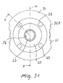
- FIG. 3A shows further features of the lid 50 in a plan view, wherein the substantially beveled end face 51 of two arranged symmetrically to the central axis M End laketeneinbuchtitch 52B (see FIG. 3B ) interrupted at its surface with at least one pin 61 (see FIG. 3B ) are provided. Following the end face 51 in the direction of the center is a first trough 59, which then merges into a second trough 62. A rotationally symmetrical pin 63 rises centrally from the second trough 62. The rotationally symmetric pin 63 has, on the inside, a first cavity 76, which is designed for the positive reception of the stabilizing sleeve 43 FIG. 1 suitable is.
- the rotationally symmetrical pin 63 together with the first 59 and the second 62 trough, form a receptacle for the attachable button 40, the identified by means of an attached coding, eg color coding, different located in the outer container 1 dental implants 30 and confusion among the different versions of dental implants 30 excludes
- FIG. 3B shows a sectional view of the lid 50 of an outer container 1 at the section line AA of FIG. 3A wherein the lid 50 has centrally a truncated cone-like element 74 on which the implant carrier 20 can be placed, as in FIG FIG. 1 shown.
- the annular sleeve 73 protruding from the surface.
- the annular sleeve 73 is formed as a continuous perimetric peripheral edge.
- the annular sleeve 73 may also be formed by a plurality of perimetric protrusions.
- a tongue-like element 75 is arranged, which in the assembled state has a substantially first rotationally symmetrical region 25A (FIG. Fig. 1 ) of the implant carrier 20 is associated with a certain play and serves to guide the implant carrier 20 during insertion. Moreover, in the assembled state, there is a clearance between the reinforcing plate 26 and the lower portion of the tongue-like member 75.
- a second cavity 77 of the lid 50 serves to receive the in the FIG. 1
- the cap-shaped portion 64 connects to the neck 53, then there is a step 66 which is adjacent to the lid removal portion 55.
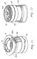
- FIG. 3C shows a top perspective view of the lid 50, wherein a plurality of recesses 60 are arranged symmetrically in the surface of the first trough 59, which are suitable for fixing the lid 50.
- a lid removal area 55 is a to the perimetrically circumferential recess 68 ( Fig. 3D ) adjacent latching tongue 79 which engages in a cutout in the locking ring 56.
- the latching tongue 79 serves to clearly define the direction of rotation of the cover 50 with respect to the securing ring 56.
- the Figure 3D shows a bottom perspective view of a lid 50 of the outer container 1, wherein the in FIG. 3 shown retaining ring 56 on its inner surface on the cylindrical body part 10 facing peripheral surface drop-shaped bulges 70 and 70A identifies, which engage in the in FIG. 2 represented recess 15 are suitable.
- the reference numeral 70 serves to clarify the drop-shaped bulges in the sectional view.
- the drop-shaped protrusions 70 A adjacent is in the direction of the body interior of the lid 50 which Predetermined breaking point 57, and between the teardrop-shaped bulges 70A and the third thread 65, a crenelated portion 72 is formed, which is in the screwed state of the cover 50 and cylindrical body portion 10, with the first bead 14 is engaged.
- the components of the outer container 1, formed from cylindrical body part 10, cover 50 and knob 40, can advantageously be obtained by conventional methods, for. B. are produced in the casting and are preferably made of plastic.
- Possible plastic materials for the outer housing is cyclo-olefin copolymer (COC), which is FDA and CE certified, as a medically applicable material and for the cap is high-density polyethylene (HDPE) or low-density polyethylene (LDPE) applicable, but also other materials that have the same or similar properties can be used.
- COC cyclo-olefin copolymer
- HDPE high-density polyethylene
- LDPE low-density polyethylene
- an outer container 1 for an implant carrier 20 comprising: a cylindrical body portion 10 and a lid 50 closing off the cylindrical body portion 10, the lid 50 being provided with a frusto-conical member 74 projecting into the cylindrical body portion 10 wherein the implant carrier 20 has a hole 25B formed complementary to the frusto-conical member 74, which tightly surrounds the frusto-conical member 74 when the implant carrier 20 is attached to the lid 50, and the frusto-conical member 74 has an annular means 73 which the hole 25B engages at a distance when the implant carrier 20 is attached to the lid 50.
Landscapes
- Health & Medical Sciences (AREA)
- Oral & Maxillofacial Surgery (AREA)
- Orthopedic Medicine & Surgery (AREA)
- Dentistry (AREA)
- Epidemiology (AREA)
- Life Sciences & Earth Sciences (AREA)
- Animal Behavior & Ethology (AREA)
- General Health & Medical Sciences (AREA)
- Public Health (AREA)
- Veterinary Medicine (AREA)
- Prostheses (AREA)
- Closures For Containers (AREA)
Priority Applications (1)
| Application Number | Priority Date | Filing Date | Title |
|---|---|---|---|
| EP08162751.5A EP2156811B1 (fr) | 2008-08-21 | 2008-08-21 | Récipient extérieur pour un support d'implant |
Applications Claiming Priority (1)
| Application Number | Priority Date | Filing Date | Title |
|---|---|---|---|
| EP08162751.5A EP2156811B1 (fr) | 2008-08-21 | 2008-08-21 | Récipient extérieur pour un support d'implant |
Publications (2)
| Publication Number | Publication Date |
|---|---|
| EP2156811A1 true EP2156811A1 (fr) | 2010-02-24 |
| EP2156811B1 EP2156811B1 (fr) | 2017-03-22 |
Family
ID=40328776
Family Applications (1)
| Application Number | Title | Priority Date | Filing Date |
|---|---|---|---|
| EP08162751.5A Not-in-force EP2156811B1 (fr) | 2008-08-21 | 2008-08-21 | Récipient extérieur pour un support d'implant |
Country Status (1)
| Country | Link |
|---|---|
| EP (1) | EP2156811B1 (fr) |
Cited By (2)
| Publication number | Priority date | Publication date | Assignee | Title |
|---|---|---|---|---|
| US7694812B2 (en) | 2007-08-09 | 2010-04-13 | Straumann Holding Ag Peter | External container for an implant carrier |
| CN105120794A (zh) * | 2013-01-23 | 2015-12-02 | 牙科材料工贸有限公司 | 用于储存、取出和携带牙科种植体的包装系统 |
Citations (5)
| Publication number | Priority date | Publication date | Assignee | Title |
|---|---|---|---|---|
| WO2000002496A1 (fr) * | 1998-07-13 | 2000-01-20 | Nobel Biocare Ab | Combinaison de support d'implant et capuchon d'etui |
| EP1145692A2 (fr) * | 2000-04-14 | 2001-10-17 | Arruga Artal, Alberto, Dr. | Implant dentaire et procédé d'implantation opératoire |
| EP1252866A1 (fr) * | 2001-04-27 | 2002-10-30 | Straumann Holding AG | Ensemble pour manipuler un implant |
| EP1523955A1 (fr) | 2003-10-16 | 2005-04-20 | Straumann Holding AG | Emballage pour la conservation d'un dispositif médical ou analogues |
| WO2006052478A1 (fr) * | 2004-10-26 | 2006-05-18 | Surgical Specialities Corporation | Appareil et procédé de stockage in vitro d’une cornée |
-
2008
- 2008-08-21 EP EP08162751.5A patent/EP2156811B1/fr not_active Not-in-force
Patent Citations (5)
| Publication number | Priority date | Publication date | Assignee | Title |
|---|---|---|---|---|
| WO2000002496A1 (fr) * | 1998-07-13 | 2000-01-20 | Nobel Biocare Ab | Combinaison de support d'implant et capuchon d'etui |
| EP1145692A2 (fr) * | 2000-04-14 | 2001-10-17 | Arruga Artal, Alberto, Dr. | Implant dentaire et procédé d'implantation opératoire |
| EP1252866A1 (fr) * | 2001-04-27 | 2002-10-30 | Straumann Holding AG | Ensemble pour manipuler un implant |
| EP1523955A1 (fr) | 2003-10-16 | 2005-04-20 | Straumann Holding AG | Emballage pour la conservation d'un dispositif médical ou analogues |
| WO2006052478A1 (fr) * | 2004-10-26 | 2006-05-18 | Surgical Specialities Corporation | Appareil et procédé de stockage in vitro d’une cornée |
Cited By (3)
| Publication number | Priority date | Publication date | Assignee | Title |
|---|---|---|---|---|
| US7694812B2 (en) | 2007-08-09 | 2010-04-13 | Straumann Holding Ag Peter | External container for an implant carrier |
| CN105120794A (zh) * | 2013-01-23 | 2015-12-02 | 牙科材料工贸有限公司 | 用于储存、取出和携带牙科种植体的包装系统 |
| CN105120794B (zh) * | 2013-01-23 | 2017-09-22 | 牙科材料工贸有限公司 | 用于储存、取出和运输牙科种植体的包装系统 |
Also Published As
| Publication number | Publication date |
|---|---|
| EP2156811B1 (fr) | 2017-03-22 |
Similar Documents
| Publication | Publication Date | Title |
|---|---|---|
| DE102007037593B4 (de) | Außenbehälter für einen Implantatträger | |
| AT404317B (de) | Verschlussvorrichtung, trennvorrichtung sowie aufnahmebehälter für eine aufnahmeeinrichtung | |
| DE69501278T2 (de) | Zwei-Komponentenpackung | |
| EP1009681B1 (fr) | Systeme de recipient a deux constituants | |
| DE69901271T2 (de) | Antiluxations-Hüftendoprothese | |
| EP0986342B1 (fr) | Conditionnement comportant un recipient et un implant dentaire dispose dans celui ci | |
| DE69605877T2 (de) | Behälter mit schraubkappe | |
| DE60019446T2 (de) | Flüssigkeitstransferset für phiolen und andere medizinische behälter | |
| DE69734248T2 (de) | Knochen-verankerungselement | |
| DE2902499A1 (de) | Behaelter mit verschluss | |
| DE69835722T2 (de) | Behälter zur getrennten Aufbewahrung und Mischung von zwei Produkten, und Verfahren zur Herstellung dieses Behälters | |
| EP1537834B1 (fr) | Appui d'implant ammélioré | |
| DE19913158A1 (de) | Vorrichtung zur Handhabung von Dental-Implantaten | |
| EP2666437A1 (fr) | Insert de rétention et dispositif de raccordement pour applications dentaires | |
| DE3325448A1 (de) | Hueftpfannen-endoprothese | |
| EP2156811B1 (fr) | Récipient extérieur pour un support d'implant | |
| DE60304443T2 (de) | Verschlussvorrichtung | |
| EP3727188A1 (fr) | Implant dentaire | |
| AT409725B (de) | Trennvorrichtung | |
| DE102018003627A1 (de) | Behälter für Anstrichmittel mit einer nachgiebigen Tasche | |
| EP1480686B1 (fr) | Conteneur sterile et ensemble de filtration destine a un conteneur sterile | |
| WO2019120607A1 (fr) | Récipient pour implant dentaire | |
| DE69603147T2 (de) | Manipulierbarer Behälter aus Kunststoff | |
| DE60036824T2 (de) | Verschlusskappe | |
| EP1963193A1 (fr) | Dispositif de fermeture universelle |
Legal Events
| Date | Code | Title | Description |
|---|---|---|---|
| PUAI | Public reference made under article 153(3) epc to a published international application that has entered the european phase |
Free format text: ORIGINAL CODE: 0009012 |
|
| AK | Designated contracting states |
Kind code of ref document: A1 Designated state(s): AT BE BG CH CY CZ DE DK EE ES FI FR GB GR HR HU IE IS IT LI LT LU LV MC MT NL NO PL PT RO SE SI SK TR |
|
| AX | Request for extension of the european patent |
Extension state: AL BA MK RS |
|
| 17P | Request for examination filed |
Effective date: 20100824 |
|
| 17Q | First examination report despatched |
Effective date: 20100917 |
|
| AKX | Designation fees paid |
Designated state(s): AT BE BG CH CY CZ DE DK EE ES FI FR GB GR HR HU IE IS IT LI LT LU LV MC MT NL NO PL PT RO SE SI SK TR |
|
| GRAP | Despatch of communication of intention to grant a patent |
Free format text: ORIGINAL CODE: EPIDOSNIGR1 |
|
| INTG | Intention to grant announced |
Effective date: 20161006 |
|
| GRAS | Grant fee paid |
Free format text: ORIGINAL CODE: EPIDOSNIGR3 |
|
| GRAA | (expected) grant |
Free format text: ORIGINAL CODE: 0009210 |
|
| AK | Designated contracting states |
Kind code of ref document: B1 Designated state(s): AT BE BG CH CY CZ DE DK EE ES FI FR GB GR HR HU IE IS IT LI LT LU LV MC MT NL NO PL PT RO SE SI SK TR |
|
| REG | Reference to a national code |
Ref country code: GB Ref legal event code: FG4D Free format text: NOT ENGLISH |
|
| REG | Reference to a national code |
Ref country code: CH Ref legal event code: EP |
|
| REG | Reference to a national code |
Ref country code: AT Ref legal event code: REF Ref document number: 876932 Country of ref document: AT Kind code of ref document: T Effective date: 20170415 |
|
| REG | Reference to a national code |
Ref country code: IE Ref legal event code: FG4D Free format text: LANGUAGE OF EP DOCUMENT: GERMAN |
|
| REG | Reference to a national code |
Ref country code: DE Ref legal event code: R096 Ref document number: 502008015136 Country of ref document: DE |
|
| REG | Reference to a national code |
Ref country code: CH Ref legal event code: NV Representative=s name: MODIANO AND PARTNERS S.A., CH |
|
| REG | Reference to a national code |
Ref country code: NL Ref legal event code: MP Effective date: 20170322 |
|
| PG25 | Lapsed in a contracting state [announced via postgrant information from national office to epo] |
Ref country code: NO Free format text: LAPSE BECAUSE OF FAILURE TO SUBMIT A TRANSLATION OF THE DESCRIPTION OR TO PAY THE FEE WITHIN THE PRESCRIBED TIME-LIMIT Effective date: 20170622 Ref country code: LT Free format text: LAPSE BECAUSE OF FAILURE TO SUBMIT A TRANSLATION OF THE DESCRIPTION OR TO PAY THE FEE WITHIN THE PRESCRIBED TIME-LIMIT Effective date: 20170322 Ref country code: HR Free format text: LAPSE BECAUSE OF FAILURE TO SUBMIT A TRANSLATION OF THE DESCRIPTION OR TO PAY THE FEE WITHIN THE PRESCRIBED TIME-LIMIT Effective date: 20170322 Ref country code: GR Free format text: LAPSE BECAUSE OF FAILURE TO SUBMIT A TRANSLATION OF THE DESCRIPTION OR TO PAY THE FEE WITHIN THE PRESCRIBED TIME-LIMIT Effective date: 20170623 Ref country code: FI Free format text: LAPSE BECAUSE OF FAILURE TO SUBMIT A TRANSLATION OF THE DESCRIPTION OR TO PAY THE FEE WITHIN THE PRESCRIBED TIME-LIMIT Effective date: 20170322 |
|
| REG | Reference to a national code |
Ref country code: LT Ref legal event code: MG4D |
|
| PG25 | Lapsed in a contracting state [announced via postgrant information from national office to epo] |
Ref country code: SE Free format text: LAPSE BECAUSE OF FAILURE TO SUBMIT A TRANSLATION OF THE DESCRIPTION OR TO PAY THE FEE WITHIN THE PRESCRIBED TIME-LIMIT Effective date: 20170322 Ref country code: LV Free format text: LAPSE BECAUSE OF FAILURE TO SUBMIT A TRANSLATION OF THE DESCRIPTION OR TO PAY THE FEE WITHIN THE PRESCRIBED TIME-LIMIT Effective date: 20170322 Ref country code: BG Free format text: LAPSE BECAUSE OF FAILURE TO SUBMIT A TRANSLATION OF THE DESCRIPTION OR TO PAY THE FEE WITHIN THE PRESCRIBED TIME-LIMIT Effective date: 20170622 |
|
| PG25 | Lapsed in a contracting state [announced via postgrant information from national office to epo] |
Ref country code: NL Free format text: LAPSE BECAUSE OF FAILURE TO SUBMIT A TRANSLATION OF THE DESCRIPTION OR TO PAY THE FEE WITHIN THE PRESCRIBED TIME-LIMIT Effective date: 20170322 |
|
| PG25 | Lapsed in a contracting state [announced via postgrant information from national office to epo] |
Ref country code: ES Free format text: LAPSE BECAUSE OF FAILURE TO SUBMIT A TRANSLATION OF THE DESCRIPTION OR TO PAY THE FEE WITHIN THE PRESCRIBED TIME-LIMIT Effective date: 20170322 Ref country code: CZ Free format text: LAPSE BECAUSE OF FAILURE TO SUBMIT A TRANSLATION OF THE DESCRIPTION OR TO PAY THE FEE WITHIN THE PRESCRIBED TIME-LIMIT Effective date: 20170322 Ref country code: RO Free format text: LAPSE BECAUSE OF FAILURE TO SUBMIT A TRANSLATION OF THE DESCRIPTION OR TO PAY THE FEE WITHIN THE PRESCRIBED TIME-LIMIT Effective date: 20170322 Ref country code: IT Free format text: LAPSE BECAUSE OF FAILURE TO SUBMIT A TRANSLATION OF THE DESCRIPTION OR TO PAY THE FEE WITHIN THE PRESCRIBED TIME-LIMIT Effective date: 20170322 Ref country code: EE Free format text: LAPSE BECAUSE OF FAILURE TO SUBMIT A TRANSLATION OF THE DESCRIPTION OR TO PAY THE FEE WITHIN THE PRESCRIBED TIME-LIMIT Effective date: 20170322 Ref country code: SK Free format text: LAPSE BECAUSE OF FAILURE TO SUBMIT A TRANSLATION OF THE DESCRIPTION OR TO PAY THE FEE WITHIN THE PRESCRIBED TIME-LIMIT Effective date: 20170322 |
|
| PG25 | Lapsed in a contracting state [announced via postgrant information from national office to epo] |
Ref country code: PT Free format text: LAPSE BECAUSE OF FAILURE TO SUBMIT A TRANSLATION OF THE DESCRIPTION OR TO PAY THE FEE WITHIN THE PRESCRIBED TIME-LIMIT Effective date: 20170724 Ref country code: PL Free format text: LAPSE BECAUSE OF FAILURE TO SUBMIT A TRANSLATION OF THE DESCRIPTION OR TO PAY THE FEE WITHIN THE PRESCRIBED TIME-LIMIT Effective date: 20170322 Ref country code: IS Free format text: LAPSE BECAUSE OF FAILURE TO SUBMIT A TRANSLATION OF THE DESCRIPTION OR TO PAY THE FEE WITHIN THE PRESCRIBED TIME-LIMIT Effective date: 20170722 |
|
| REG | Reference to a national code |
Ref country code: DE Ref legal event code: R097 Ref document number: 502008015136 Country of ref document: DE |
|
| PLBE | No opposition filed within time limit |
Free format text: ORIGINAL CODE: 0009261 |
|
| STAA | Information on the status of an ep patent application or granted ep patent |
Free format text: STATUS: NO OPPOSITION FILED WITHIN TIME LIMIT |
|
| PG25 | Lapsed in a contracting state [announced via postgrant information from national office to epo] |
Ref country code: DK Free format text: LAPSE BECAUSE OF FAILURE TO SUBMIT A TRANSLATION OF THE DESCRIPTION OR TO PAY THE FEE WITHIN THE PRESCRIBED TIME-LIMIT Effective date: 20170322 |
|
| 26N | No opposition filed |
Effective date: 20180102 |
|
| PG25 | Lapsed in a contracting state [announced via postgrant information from national office to epo] |
Ref country code: SI Free format text: LAPSE BECAUSE OF FAILURE TO SUBMIT A TRANSLATION OF THE DESCRIPTION OR TO PAY THE FEE WITHIN THE PRESCRIBED TIME-LIMIT Effective date: 20170322 |
|
| PG25 | Lapsed in a contracting state [announced via postgrant information from national office to epo] |
Ref country code: MC Free format text: LAPSE BECAUSE OF FAILURE TO SUBMIT A TRANSLATION OF THE DESCRIPTION OR TO PAY THE FEE WITHIN THE PRESCRIBED TIME-LIMIT Effective date: 20170322 |
|
| GBPC | Gb: european patent ceased through non-payment of renewal fee |
Effective date: 20170821 |
|
| REG | Reference to a national code |
Ref country code: FR Ref legal event code: ST Effective date: 20180430 |
|
| REG | Reference to a national code |
Ref country code: IE Ref legal event code: MM4A |
|
| REG | Reference to a national code |
Ref country code: BE Ref legal event code: MM Effective date: 20170831 |
|
| PG25 | Lapsed in a contracting state [announced via postgrant information from national office to epo] |
Ref country code: LU Free format text: LAPSE BECAUSE OF NON-PAYMENT OF DUE FEES Effective date: 20170821 |
|
| PG25 | Lapsed in a contracting state [announced via postgrant information from national office to epo] |
Ref country code: GB Free format text: LAPSE BECAUSE OF NON-PAYMENT OF DUE FEES Effective date: 20170821 Ref country code: IE Free format text: LAPSE BECAUSE OF NON-PAYMENT OF DUE FEES Effective date: 20170821 |
|
| PG25 | Lapsed in a contracting state [announced via postgrant information from national office to epo] |
Ref country code: BE Free format text: LAPSE BECAUSE OF NON-PAYMENT OF DUE FEES Effective date: 20170831 Ref country code: FR Free format text: LAPSE BECAUSE OF NON-PAYMENT OF DUE FEES Effective date: 20170831 |
|
| PG25 | Lapsed in a contracting state [announced via postgrant information from national office to epo] |
Ref country code: MT Free format text: LAPSE BECAUSE OF FAILURE TO SUBMIT A TRANSLATION OF THE DESCRIPTION OR TO PAY THE FEE WITHIN THE PRESCRIBED TIME-LIMIT Effective date: 20170322 |
|
| REG | Reference to a national code |
Ref country code: AT Ref legal event code: MM01 Ref document number: 876932 Country of ref document: AT Kind code of ref document: T Effective date: 20170821 |
|
| PGFP | Annual fee paid to national office [announced via postgrant information from national office to epo] |
Ref country code: DE Payment date: 20180823 Year of fee payment: 11 |
|
| PG25 | Lapsed in a contracting state [announced via postgrant information from national office to epo] |
Ref country code: AT Free format text: LAPSE BECAUSE OF NON-PAYMENT OF DUE FEES Effective date: 20170821 |
|
| PGFP | Annual fee paid to national office [announced via postgrant information from national office to epo] |
Ref country code: CH Payment date: 20180822 Year of fee payment: 11 |
|
| PG25 | Lapsed in a contracting state [announced via postgrant information from national office to epo] |
Ref country code: HU Free format text: LAPSE BECAUSE OF FAILURE TO SUBMIT A TRANSLATION OF THE DESCRIPTION OR TO PAY THE FEE WITHIN THE PRESCRIBED TIME-LIMIT; INVALID AB INITIO Effective date: 20080821 |
|
| PG25 | Lapsed in a contracting state [announced via postgrant information from national office to epo] |
Ref country code: CY Free format text: LAPSE BECAUSE OF NON-PAYMENT OF DUE FEES Effective date: 20170322 |
|
| REG | Reference to a national code |
Ref country code: DE Ref legal event code: R119 Ref document number: 502008015136 Country of ref document: DE |
|
| PG25 | Lapsed in a contracting state [announced via postgrant information from national office to epo] |
Ref country code: TR Free format text: LAPSE BECAUSE OF FAILURE TO SUBMIT A TRANSLATION OF THE DESCRIPTION OR TO PAY THE FEE WITHIN THE PRESCRIBED TIME-LIMIT Effective date: 20170322 |
|
| PG25 | Lapsed in a contracting state [announced via postgrant information from national office to epo] |
Ref country code: LI Free format text: LAPSE BECAUSE OF NON-PAYMENT OF DUE FEES Effective date: 20190831 Ref country code: CH Free format text: LAPSE BECAUSE OF NON-PAYMENT OF DUE FEES Effective date: 20190831 |
|
| PG25 | Lapsed in a contracting state [announced via postgrant information from national office to epo] |
Ref country code: DE Free format text: LAPSE BECAUSE OF NON-PAYMENT OF DUE FEES Effective date: 20200303 |