EP2156873A1 - Filterelement, Sicherungsring und Filterverfahren - Google Patents
Filterelement, Sicherungsring und Filterverfahren Download PDFInfo
- Publication number
- EP2156873A1 EP2156873A1 EP08014380A EP08014380A EP2156873A1 EP 2156873 A1 EP2156873 A1 EP 2156873A1 EP 08014380 A EP08014380 A EP 08014380A EP 08014380 A EP08014380 A EP 08014380A EP 2156873 A1 EP2156873 A1 EP 2156873A1
- Authority
- EP
- European Patent Office
- Prior art keywords
- connecting means
- securing ring
- tubular portion
- filter element
- filter
- Prior art date
- Legal status (The legal status is an assumption and is not a legal conclusion. Google has not performed a legal analysis and makes no representation as to the accuracy of the status listed.)
- Granted
Links
- 238000001914 filtration Methods 0.000 title claims abstract description 33
- 238000000034 method Methods 0.000 title claims description 12
- 239000002002 slurry Substances 0.000 claims abstract description 13
- 238000003825 pressing Methods 0.000 claims abstract description 6
- 239000012858 resilient material Substances 0.000 claims description 4
- 229920001971 elastomer Polymers 0.000 claims description 2
- 239000000463 material Substances 0.000 claims description 2
- 239000004744 fabric Substances 0.000 description 8
- 239000012065 filter cake Substances 0.000 description 4
- 239000007788 liquid Substances 0.000 description 4
- 239000000706 filtrate Substances 0.000 description 2
- 238000009434 installation Methods 0.000 description 2
- 239000007787 solid Substances 0.000 description 2
- 238000004026 adhesive bonding Methods 0.000 description 1
- 230000008602 contraction Effects 0.000 description 1
- 230000001419 dependent effect Effects 0.000 description 1
- 238000009826 distribution Methods 0.000 description 1
- 230000002708 enhancing effect Effects 0.000 description 1
- 238000003780 insertion Methods 0.000 description 1
- 230000037431 insertion Effects 0.000 description 1
- 238000005304 joining Methods 0.000 description 1
- 239000012528 membrane Substances 0.000 description 1
- 239000000203 mixture Substances 0.000 description 1
- 238000000926 separation method Methods 0.000 description 1
- 238000009958 sewing Methods 0.000 description 1
- 239000004753 textile Substances 0.000 description 1
- 229920002725 thermoplastic elastomer Polymers 0.000 description 1
- 238000003466 welding Methods 0.000 description 1
Images
Classifications
-
- B—PERFORMING OPERATIONS; TRANSPORTING
- B01—PHYSICAL OR CHEMICAL PROCESSES OR APPARATUS IN GENERAL
- B01D—SEPARATION
- B01D25/00—Filters formed by clamping together several filtering elements or parts of such elements
- B01D25/12—Filter presses, i.e. of the plate or plate and frame type
- B01D25/176—Filter presses, i.e. of the plate or plate and frame type attaching the filter element to the filter press plates, e.g. around the central feed hole in the plates
-
- Y—GENERAL TAGGING OF NEW TECHNOLOGICAL DEVELOPMENTS; GENERAL TAGGING OF CROSS-SECTIONAL TECHNOLOGIES SPANNING OVER SEVERAL SECTIONS OF THE IPC; TECHNICAL SUBJECTS COVERED BY FORMER USPC CROSS-REFERENCE ART COLLECTIONS [XRACs] AND DIGESTS
- Y10—TECHNICAL SUBJECTS COVERED BY FORMER USPC
- Y10S—TECHNICAL SUBJECTS COVERED BY FORMER USPC CROSS-REFERENCE ART COLLECTIONS [XRACs] AND DIGESTS
- Y10S277/00—Seal for a joint or juncture
- Y10S277/918—Seal combined with filter or fluid separator
Definitions
- the present invention relates to a filter element for a press filter comprising first and second filtering means, each having at least one opening for the passage of a slurry to be filtered, and first and second connecting means for connecting the openings of the first and second filtering means, each of the first and second connecting means comprising a flange portion and a tubular portion, wherein the flange portion of the first connecting means is fixedly attached to the first filtering means and the flange portion of the second connecting means is fixedly attached to the second filtering means, and wherein the tubular portion of the first connecting means is insertable into the tubular portion of the second connecting means, according to the preamble of claim 1.
- the invention further relates to a securing ring to be inserted into a filter element, according to the preamble of claim 10.
- the invention in a third aspect relates to a method for filtering a slurry by means of a press filter having at least one filter plate with a feed port, according to the preamble of claim 11.
- a filter press is a well-known and efficient apparatus for separating solids and liquids.
- Filter presses generally comprise a plurality of filter plates, which are stacked and clamped together on their peripheries, thereby forming filter chambers between the stacked filter plates.
- Each filter plate includes a feed port for a slurry to be filtered, which is formed as a through hole connecting two adjacent filter chambers.
- slurry refers to a mixture of liquid and solids that is introduced to a filter press for separation.
- Both sides of the filter plates are covered with filtering means, e.g. a filtering cloth or membrane.
- the filtering means are provided with a feed hole corresponding to the feed port of the filter plate.
- the filtering means are interconnected in a leak-proof manner in the region of the feed port, so as to prevent the slurry from escaping between the filter plate and the filtering means in the region of the feed port.
- the slurry to be filtered enters the filter press via an inlet port provided at one side of the filter press and is distributed to the filter chambers via the feed ports in the filter plates.
- the liquid is filtered by passing through the filtering means, forming a filter cake in the filter chambers.
- the filtered liquid (filtrate) leaves the press filter via filtrate ports in the filter plates.
- EP 1 925 351 A1 which forms the basis for the preamble of claim 1, discloses a connecting device for connecting two filtering means of a press filter.
- the connecting device comprises two flange elements, which can be connected to each other by an axial insertion of one flange element into the other and a subsequent relative turning.
- a sleeve comprising a flange portion at one side and an annular groove at another side is introduced into an opening formed by two flange rings.
- a locking ring is inserted into the annular groove for axially locking the two flange rings.
- US 6,971,526 B2 discloses a method for fixedly joining a filter cloth to a filter plate using a flanged cloth connector ring.
- the flanged cloth connector ring is attached to the filter cloth around a feed port of the cloth and inserted into a receiving channel in the filter plate.
- a locking ring or a distribution ring may be inserted into the channel adjacent to the connector ring to retain the connector ring in place.
- the object of the invention is to provide a filter element for a press filter and a method for filtering a slurry, which permit an easy assembly and a reliable connection of two filtering means.
- the object is in a first aspect of the invention achieved by a filter element for a press filter according to claim 1.
- the object is further achieved by a securing ring according to claim 10 and a method for filtering a slurry according to claim 11.
- Preferred embodiments of the invention are described in the dependent claims and the following description together with the accompanying drawings.
- the filter element is characterized in that a securing ring is provided, which is insertable into the tubular portion of the first connecting means and is adapted to exert a radial force on the tubular portion of the first connecting means, pressing the tubular portion of the first connecting means against the tubular portion of the second connecting means.
- One basic idea of the invention is to achieve a reliable and leak-proof connection of two connecting means by radially pressing one connecting means against the other.
- the radial pressing enhances the tightness of the connection and seals the two connecting means.
- An important aspect of the invention is to provide a separate element - namely the securing ring - in addition to the first and second connecting means in order to tightly couple the connecting means.
- the provision of a separate element allows for a quick and easy assembly of the filter element.
- the tubular portion of the first connecting means is introduced into the tubular portion of the second connecting means. This step can be easily accomplished without an excessively tight fit, i.e. high friction, between the two connecting means.
- the securing ring is inserted into the tubular portion of the first connecting means, pressing the tubular portion of the first connecting means against the tubular portion of the second connecting means. With the securing ring, the friction between the two elements is increased, achieving a friction fit and/or a sealed connection between the first and second connecting means.
- At least one of the first and second connecting means comprises a resilient material, particularly a rubber material.
- the resilient material can also be a thermoplastic elastomer.
- the first connecting means is made up of a resilient material.
- the first connecting means should be adapted to allow for an at least slight increase of the diameter of its for example tubular portion.
- the tubular portions of the first and second connecting means comprise corresponding engagement means provided on an outer surface of the tubular portion of the first connecting means and an inner surface of the tubular portion of the second connecting means, respectively.
- These additional engagement means enhance the tightness of the connection by providing a form-locking or snap connection in addition to the frictional connection.
- the engagement means can assist an operator in identifying a desired relative position of the two connecting means by providing a tactile feedback once the desired position is reached.
- the engagement means preferably include at least one protrusion and one recess, in particular a circular protrusion and a corresponding circular recess.
- the protrusion and the recess could also comprise another cross-sectional shape like a square or rectangle etc.
- the first connecting means comprises a ring-shaped receiving portion provided at an inner surface of its tubular portion for receiving the securing ring.
- the receiving portion is preferably constructed as a circular groove having a width substantially equal to a width of the securing ring.
- the receiving portion allows for a defined placement of the securing ring in the tubular portion of the first connecting means. Moreover, the receiving portion securely retains the securing ring in place.
- the securing ring has a relaxed state, in which an outer diameter is larger than an inner diameter of the tubular portion of the first connecting means, and a tensioned state, in which the diameter of the securing ring is smaller than the inner diameter of the tubular portion of the first connecting means.
- the securing ring when no force is applied to the securing ring, the securing ring has an outer diameter, which is larger than an inner diameter of the tubular portion of the first connecting means.
- the securing ring is adapted to be tensioned in a way that its diameter is reduced. In this tensioned state, the securing ring tends to expand, thereby exerting a force, which is directed radially outward.
- a preferred embodiment of the securing ring is given by a securing ring comprising an opening, thereby forming an open ring with two end portions adjacent to the opening.
- the open ring permits to contract the ring, thereby reducing its diameter.
- the end portions of the securing ring are formed in a stepped manner.
- the stepped end portions are preferably equally formed, such that the highest step of one end portion is flush with the lowest step of the other end portion and vice versa. This embodiment allow for a smaller opening of the ring in a transverse direction, while at the same time maintaining the degree of possible contraction of the ring.
- a particularly preferred embodiment of the securing ring is characterized in that the stepped end portions of the securing ring are formed by first and second lips, respectively, integrally formed with the securing ring, wherein the first lip has a parallel offset with regard to the second lip.
- the lips are equally sized and each lip takes up approximately half of the overall width of the securing ring. The provision of two lips provides the advantage that the surface for exerting the radial force is increased.
- Another preferred embodiment of the filter element is characterized in that in a relaxed and a tensioned state of the securing ring, the lips overlap in a transverse direction of the securing ring.
- This embodiment is particularly advantageous, as - although the ring is formed as an open ring - it can exert a radial force over its entire circumference.
- the securing ring is capable of exerting a pressure substantially equally distributed over a circumferential surface.
- a securing ring according to claim 10.
- the securing ring is to be inserted into a filter element of a press filter and comprises a ring body having a relaxed state with a predetermined diameter and a tensioned state, in which the diameter is reduced.
- the connecting means can be quickly and easily connected.
- the object is solved by a method for filtering a slurry by means of a press filter according to claim 11.
- the method is characterized in that a filter element is arranged on a filter plate and first and second connecting means are inserted into a feed port of a filter plate and connected therein by means of a securing ring. Subsequently the slurry is filtered, wherein a filter cake is built up on the filtering means. When the filter cake has reached a predetermined thickness, the filter is opened and the filter cake is removed. If necessary, the filter elements are cleaned and/or replaced. The filter is then closed again and the filtering process is repeated.
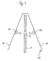
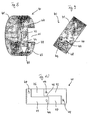
- Fig. 1 illustrates a general set-up of a filter element 10 comprising first and second connecting means 20, 30 and first and second filtering means 12, 14.
- the filter element 10 is mounted on a filter plate 5 by inserting the connecting means 20, 30 into a feed port 7, formed as a through hole.
- the feed port 7 is centrally arranged on the filter plate 5.
- the connecting means 20, 30 are interconnected, as will be described later.
- the filtering means 12, 14 are formed by a one-piece filter cloth, e.g. a textile. The filter cloth is wrapped around the filter plate 5.
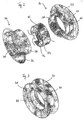
- Fig. 2 shows an embodiment of a first connecting means 20, a second connecting means 30 and a securing ring 40 in a disassembled state.
- the first connecting means 20 comprises a flange portion 22 and a tubular portion 24.
- the second connecting means 30 comprises a flange portion 32 and a tubular portion 34.
- the tubular portion 24 of the first connecting means 20 is adapted to fit into the tubular portion 34 of the second connecting means 30.
- An annular protrusion 26 is provided on an outer circumference of the tubular portion 24 of the first connecting means 20, corresponding to an annular groove 36 arranged on an inner surface of the tubular portion 34 of the second connecting means 30.
- the filtering means 12, 14, not shown in the embodiment of Fig. 2 are firmly connected to the flange portions 22, 32 of the connecting means 20, 30. Possible methods for the fixation of the filtering means 12, 14 to the flange portions 22, 32 include gluing, welding, sewing or other bonding techniques.
- Fig. 3 shows the connecting means 20, 30 and the securing ring 40 in an assembled state.
- the securing ring 40 is received in a receiving portion 28 provided at an inner surface of the tubular portion 24 of the first connecting means 20 (see Fig. 1 ).
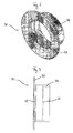
- Figures 4 and 5 show an embodiment of the first connecting means 20.
- Fig. 4 shows a perspective view of the first connecting means 20.
- Fig. 5 shows a side view of the first connecting means 20, wherein the inner circumferential surface is shown in dashed lines.
- the receiving portion 28 is formed as an annular groove arranged substantially centrally in the tubular portion 24. The width of the groove corresponds to the width of the securing ring 40.
- the connecting means 20 comprises a chamfered area 29 in the region of the flange portion 22. In this chamfered area 29 the inner diameter of the connecting means 20 increases towards the flange portion 22, from where the securing ring 40 is to be installed.
- Figures 6 and 7 show the second connecting means 30.
- Fig. 6 shows a perspective view of the second connecting means 30.
- Fig. 7 shows a side view of the second connecting means 30, wherein the inner circumferential surface is shown in dashed lines.
- An annular groove 36 corresponding to the annular protrusion 26 is formed on an inner surface of the tubular portion 34.
- the second connecting means 30 comprises a chamfered area 39 in the region of the flange portion 32. The provision of two chamfered areas 29, 39 allows for an installation of the securing ring 40 alternatively from the side of the first connecting means 20 or the second connecting means 30.
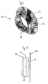
- Figures 8 to 10 show details of an embodiment of the securing ring 40.
- the securing ring 40 is formed as an open ring with an opening 45.
- the opening 45 is formed in the shape of a Z and comprises two substantially equally sized first and second opening portions 46, 47 and a narrow slit 48 (see Fig. 10 ).
- the first opening portion 46 is located on a first axial section of the securing ring 40, whereas the second opening portion 47 is located on a second axial section of the securing ring 40.
- first and second opening portions 46, 47 have an offset in a circumferential direction of the securing ring 40.
- the slit 48 extends in a circumferential direction of the ring 40 and interconnects the opening portions 46 and 47.
- the securing ring 40 comprises a main portion 41 and two lips 42, 43, which are integrally formed with the main portion 41.
- the main portion 41 has a width corresponding to the width of the securing ring 40.
- the lips 42, 43 each have a width being smaller than the width of the securing ring 40. In the embodiment shown, the lips have a width amounting to approximately half of the width of the securing ring 40.
- Each lip 42, 43 is aligned with one of the opening portions 46, 47.
- Fig. 9 shows the securing ring 40 in a tensioned state.
- the securing ring is tensioned by moving the lips 42, 43 into the opening portions 46, 47, thereby reducing the diameter of the securing ring 40.
- end portions of the lips 42, 43 abut on end portions of the main body 41.
- the diameter of the securing ring 40 in this maximally tensioned state is only slightly smaller than the inner diameter of the tubular portion 24 of the first connecting means 20.
- Fig. 10 shows a side view of the securing ring 40.
- the securing ring 40 are formed four holes 44, which can be engaged by an engagement device in order to convert the securing ring 40 from the un-tensioned state into the tensioned state.
- This engagement device can e.g. be a gripper or pliers.
- two pairs of holes a provided, each pair having one hole located on the main body 41 and a second hole on a lip 42, 43.
- the holes 44 are arranged such that the hole provided on the main portion 41 is aligned in a circumferential direction with the hole provided on the lip 42, 43.
- the opening 45 does not extend over the entire width of the ring 40, neither in the tensioned nor in the un-tensioned state. This very important feature results in a substantially equal radial force over the entire circumference of the securing ring 40, thereby enhancing the tightness of the fit between the first and the second connecting means 20, 30.
Landscapes
- Chemical & Material Sciences (AREA)
- Chemical Kinetics & Catalysis (AREA)
- Filtration Of Liquid (AREA)
Priority Applications (3)
| Application Number | Priority Date | Filing Date | Title |
|---|---|---|---|
| ES08014380T ES2391484T3 (es) | 2008-08-12 | 2008-08-12 | Elemento de filtro, anillo de fijación y procedimiento de filtrado |
| EP08014380A EP2156873B1 (de) | 2008-08-12 | 2008-08-12 | Filterelement, Sicherungsring und Filterverfahren |
| US12/538,667 US8197685B2 (en) | 2008-08-12 | 2009-08-10 | Filter element, securing ring and method for filtering |
Applications Claiming Priority (1)
| Application Number | Priority Date | Filing Date | Title |
|---|---|---|---|
| EP08014380A EP2156873B1 (de) | 2008-08-12 | 2008-08-12 | Filterelement, Sicherungsring und Filterverfahren |
Publications (2)
| Publication Number | Publication Date |
|---|---|
| EP2156873A1 true EP2156873A1 (de) | 2010-02-24 |
| EP2156873B1 EP2156873B1 (de) | 2012-07-18 |
Family
ID=40223712
Family Applications (1)
| Application Number | Title | Priority Date | Filing Date |
|---|---|---|---|
| EP08014380A Not-in-force EP2156873B1 (de) | 2008-08-12 | 2008-08-12 | Filterelement, Sicherungsring und Filterverfahren |
Country Status (3)
| Country | Link |
|---|---|
| US (1) | US8197685B2 (de) |
| EP (1) | EP2156873B1 (de) |
| ES (1) | ES2391484T3 (de) |
Families Citing this family (10)
| Publication number | Priority date | Publication date | Assignee | Title |
|---|---|---|---|---|
| US20080017592A1 (en) * | 2006-06-26 | 2008-01-24 | Christoph Maurer | Filter element for a filter press plate |
| EP2156873B1 (de) * | 2008-08-12 | 2012-07-18 | Sefar AG | Filterelement, Sicherungsring und Filterverfahren |
| DE102010007010B4 (de) * | 2010-02-05 | 2011-09-01 | Aktiebolaget Skf | Verschleißschutzhülse |
| KR101153286B1 (ko) * | 2010-03-24 | 2012-06-07 | 주식회사 코아비스 | 연료펌프 모듈의 인탱크필터 |
| WO2013091184A1 (zh) | 2011-12-21 | 2013-06-27 | Ng Ying Yuk | 针刺无纺布、其制造方法和由该无纺布形成的过滤器和吸音材料 |
| PL2897708T3 (pl) * | 2012-05-16 | 2017-09-29 | Flsmidth A/S | Tkanina filtracyjna do szybkiej wymiany |
| US9457297B2 (en) | 2012-12-04 | 2016-10-04 | Lawrence Livermore National Security, Llc | Method of securing filter elements |
| JP6380364B2 (ja) * | 2015-12-17 | 2018-08-29 | 株式会社デンソー | 燃料ポンプ及び燃料ポンプモジュール |
| CN115155123B (zh) * | 2022-07-14 | 2024-04-16 | 景津装备股份有限公司 | 一种角进料防腐板滤布的固定方法 |
| WO2026006380A1 (en) * | 2024-06-25 | 2026-01-02 | Micronics, Inc. | Filter assembly for a filter press |
Citations (6)
| Publication number | Priority date | Publication date | Assignee | Title |
|---|---|---|---|---|
| JPH0599491A (ja) * | 1990-05-02 | 1993-04-20 | Kiyoowa Nasuta:Kk | 換気用伸縮パイプ |
| DE9312880U1 (de) * | 1993-08-27 | 1993-10-14 | Pflitsch GmbH & Co KG, 42499 Hückeswagen | Kombinierte Schlauch- und Kabelverschraubung |
| WO1995007743A1 (en) * | 1993-09-14 | 1995-03-23 | Scapa Group Plc | Filter element fixation for filter presses |
| DE10156199C1 (de) | 2001-11-15 | 2002-11-21 | Lenser Filtration Gmbh & Co | Filterelement, insbesondere Kammerfilterplatte für eine Filterpresse |
| US6971526B2 (en) | 2002-09-30 | 2005-12-06 | Micronics, Inc. | Filter cloth connector |
| EP1925351A1 (de) | 2006-11-16 | 2008-05-28 | Sefar AG | Filterelement für eine Filterpressenplatte |
Family Cites Families (23)
| Publication number | Priority date | Publication date | Assignee | Title |
|---|---|---|---|---|
| US1316465A (en) * | 1919-09-16 | Eheet | ||
| US772132A (en) * | 1904-04-11 | 1904-10-11 | Joseph Crossley | Filter-cloth. |
| US1801933A (en) * | 1929-03-06 | 1931-04-21 | Andrew A Ouss | Filter press |
| US2383868A (en) * | 1943-12-02 | 1945-08-28 | Du Pont | Filtering device |
| DE1761556C3 (de) * | 1968-06-06 | 1974-05-22 | Passavant Werke | Filterplatte fuer Kammer- oder Rahmenfilterpressen |
| US4053416A (en) * | 1976-09-13 | 1977-10-11 | Air Filters, Inc. | Filter press assembly |
| US4237009A (en) * | 1978-11-28 | 1980-12-02 | Kurita Machinery Manufacturing Company Limited | Filtration-compression type filter press |
| US4217224A (en) * | 1978-11-28 | 1980-08-12 | Envirotech Corporation | Filter plate |
| AT365090B (de) * | 1980-04-16 | 1981-12-10 | Inkomag | Filtriereinrichtung |
| US4491519A (en) * | 1982-11-19 | 1985-01-01 | Kurita Machinery Manufacturing Company Limited | Filter cloth arrangement for use in fixed filter cloth type filter press |
| US4931178A (en) * | 1985-04-16 | 1990-06-05 | W. L. Gore & Associates, Inc. | Filter cloth assembly |
| GB8517311D0 (en) * | 1985-07-09 | 1985-08-14 | Heath C A | Filtercloths |
| US4954378A (en) * | 1988-11-18 | 1990-09-04 | Goodman Allan L | Repair kit for shower curtain and the like |
| DE3906537A1 (de) * | 1989-03-02 | 1990-09-06 | Passavant Werke | Filterplatten fuer plattenfilterpressen |
| DE4227670A1 (de) * | 1992-08-21 | 1994-02-24 | Friedrich Lob | Befestigungselement |
| US6149806A (en) * | 1995-05-12 | 2000-11-21 | Baer; William | Two piece frame and two piece diaphragm filter plate |
| US5958173A (en) * | 1998-01-22 | 1999-09-28 | Micronics | Method of fabricating a filter screen |
| DE19956617A1 (de) * | 1999-11-25 | 2001-06-07 | Hoesch & Soehne Eberhard | Filterplatte einer Filterpresse |
| GB0012585D0 (en) * | 2000-05-23 | 2000-07-12 | Madison Filter Ltd | Filter element fixation for filter presses |
| US7001322B2 (en) * | 2000-10-04 | 2006-02-21 | Zymequest, Inc. | Multiple processing chamber set and use thereof |
| US7635132B2 (en) * | 2002-09-30 | 2009-12-22 | Micronics, Inc. | Filter cloth connector |
| EP1923114B1 (de) * | 2006-11-16 | 2012-08-01 | Sefar AG | Filterelement, insbesondere Filterpressenplatte |
| EP2156873B1 (de) * | 2008-08-12 | 2012-07-18 | Sefar AG | Filterelement, Sicherungsring und Filterverfahren |
-
2008
- 2008-08-12 EP EP08014380A patent/EP2156873B1/de not_active Not-in-force
- 2008-08-12 ES ES08014380T patent/ES2391484T3/es active Active
-
2009
- 2009-08-10 US US12/538,667 patent/US8197685B2/en not_active Expired - Fee Related
Patent Citations (6)
| Publication number | Priority date | Publication date | Assignee | Title |
|---|---|---|---|---|
| JPH0599491A (ja) * | 1990-05-02 | 1993-04-20 | Kiyoowa Nasuta:Kk | 換気用伸縮パイプ |
| DE9312880U1 (de) * | 1993-08-27 | 1993-10-14 | Pflitsch GmbH & Co KG, 42499 Hückeswagen | Kombinierte Schlauch- und Kabelverschraubung |
| WO1995007743A1 (en) * | 1993-09-14 | 1995-03-23 | Scapa Group Plc | Filter element fixation for filter presses |
| DE10156199C1 (de) | 2001-11-15 | 2002-11-21 | Lenser Filtration Gmbh & Co | Filterelement, insbesondere Kammerfilterplatte für eine Filterpresse |
| US6971526B2 (en) | 2002-09-30 | 2005-12-06 | Micronics, Inc. | Filter cloth connector |
| EP1925351A1 (de) | 2006-11-16 | 2008-05-28 | Sefar AG | Filterelement für eine Filterpressenplatte |
Also Published As
| Publication number | Publication date |
|---|---|
| US20100200518A1 (en) | 2010-08-12 |
| ES2391484T3 (es) | 2012-11-27 |
| EP2156873B1 (de) | 2012-07-18 |
| US8197685B2 (en) | 2012-06-12 |
Similar Documents
| Publication | Publication Date | Title |
|---|---|---|
| EP2156873B1 (de) | Filterelement, Sicherungsring und Filterverfahren | |
| CA2858717C (en) | Clamp assembly with annular clamps and bridge | |
| KR100928760B1 (ko) | 여과부재 및 여과조립체의 조립방법 | |
| EP1088640B1 (de) | Verfahren zum Dichten eines Filterelements in einer Filterkassette und so hergestellte Filtervorrichtungen | |
| KR100398515B1 (ko) | 유체필터용필터요소 | |
| WO2012162454A1 (en) | Assembly with separately tightenable annular clamps | |
| PL174556B1 (pl) | Wkład filtracyjny do wieży filtracyjnej | |
| CA3068106A1 (en) | Assembly comprising a filter plate and an attachment part | |
| US6971526B2 (en) | Filter cloth connector | |
| CA2629386C (en) | Filter cloth connector | |
| US6007717A (en) | Filter cloths incorporating a feed passage connector for use with plate-type filter presses | |
| EP0808204B1 (de) | Filtervorrichtung | |
| US5603827A (en) | Membrane filter plate | |
| GB2088231A (en) | Improvements in filter cloths for filter presses | |
| EP4349447B1 (de) | Filtermembran für einen eingelassenen plattenfilter, membranfilterplatte, membranfüllplattenanordnung und versenkter plattenfilter | |
| US6183529B1 (en) | High temperature gas filter assembly | |
| US11478730B2 (en) | Filter press assembly | |
| US6835310B2 (en) | Device for coupling together a tube and a filter housing | |
| JP3751362B2 (ja) | フイルタープレスの濾板 | |
| CN110559727B (zh) | 用于真空和/或压力过滤装置的过滤鼓 | |
| KR101441249B1 (ko) | 필터프레스용 여과필터 및 이를 이용한 설치방법 | |
| CA1292955C (en) | Twist on disposable filter | |
| ITFO970011A1 (it) | Filtro a dischi perfezionato |
Legal Events
| Date | Code | Title | Description |
|---|---|---|---|
| PUAI | Public reference made under article 153(3) epc to a published international application that has entered the european phase |
Free format text: ORIGINAL CODE: 0009012 |
|
| 17P | Request for examination filed |
Effective date: 20090302 |
|
| AK | Designated contracting states |
Kind code of ref document: A1 Designated state(s): AT BE BG CH CY CZ DE DK EE ES FI FR GB GR HR HU IE IS IT LI LT LU LV MC MT NL NO PL PT RO SE SI SK TR |
|
| AX | Request for extension of the european patent |
Extension state: AL BA MK RS |
|
| AKX | Designation fees paid |
Designated state(s): AT BE BG CH CY CZ DE DK EE ES FI FR GB GR HR HU IE IS IT LI LT LU LV MC MT NL NO PL PT RO SE SI SK TR |
|
| 17Q | First examination report despatched |
Effective date: 20101103 |
|
| GRAP | Despatch of communication of intention to grant a patent |
Free format text: ORIGINAL CODE: EPIDOSNIGR1 |
|
| GRAS | Grant fee paid |
Free format text: ORIGINAL CODE: EPIDOSNIGR3 |
|
| GRAA | (expected) grant |
Free format text: ORIGINAL CODE: 0009210 |
|
| AK | Designated contracting states |
Kind code of ref document: B1 Designated state(s): AT BE BG CH CY CZ DE DK EE ES FI FR GB GR HR HU IE IS IT LI LT LU LV MC MT NL NO PL PT RO SE SI SK TR |
|
| REG | Reference to a national code |
Ref country code: GB Ref legal event code: FG4D |
|
| REG | Reference to a national code |
Ref country code: CH Ref legal event code: EP |
|
| REG | Reference to a national code |
Ref country code: AT Ref legal event code: REF Ref document number: 566802 Country of ref document: AT Kind code of ref document: T Effective date: 20120815 Ref country code: IE Ref legal event code: FG4D |
|
| REG | Reference to a national code |
Ref country code: DE Ref legal event code: R096 Ref document number: 602008017234 Country of ref document: DE Effective date: 20120913 |
|
| REG | Reference to a national code |
Ref country code: CH Ref legal event code: PL |
|
| PG25 | Lapsed in a contracting state [announced via postgrant information from national office to epo] |
Ref country code: LI Free format text: LAPSE BECAUSE OF THE APPLICANT RENOUNCES Effective date: 20120718 Ref country code: CH Free format text: LAPSE BECAUSE OF THE APPLICANT RENOUNCES Effective date: 20120718 |
|
| REG | Reference to a national code |
Ref country code: ES Ref legal event code: FG2A Ref document number: 2391484 Country of ref document: ES Kind code of ref document: T3 Effective date: 20121127 |
|
| REG | Reference to a national code |
Ref country code: NL Ref legal event code: VDEP Effective date: 20120718 |
|
| REG | Reference to a national code |
Ref country code: AT Ref legal event code: MK05 Ref document number: 566802 Country of ref document: AT Kind code of ref document: T Effective date: 20120718 |
|
| REG | Reference to a national code |
Ref country code: LT Ref legal event code: MG4D Effective date: 20120718 |
|
| PG25 | Lapsed in a contracting state [announced via postgrant information from national office to epo] |
Ref country code: AT Free format text: LAPSE BECAUSE OF FAILURE TO SUBMIT A TRANSLATION OF THE DESCRIPTION OR TO PAY THE FEE WITHIN THE PRESCRIBED TIME-LIMIT Effective date: 20120718 Ref country code: CY Free format text: LAPSE BECAUSE OF FAILURE TO SUBMIT A TRANSLATION OF THE DESCRIPTION OR TO PAY THE FEE WITHIN THE PRESCRIBED TIME-LIMIT Effective date: 20120718 Ref country code: LT Free format text: LAPSE BECAUSE OF FAILURE TO SUBMIT A TRANSLATION OF THE DESCRIPTION OR TO PAY THE FEE WITHIN THE PRESCRIBED TIME-LIMIT Effective date: 20120718 Ref country code: IS Free format text: LAPSE BECAUSE OF FAILURE TO SUBMIT A TRANSLATION OF THE DESCRIPTION OR TO PAY THE FEE WITHIN THE PRESCRIBED TIME-LIMIT Effective date: 20121118 Ref country code: FI Free format text: LAPSE BECAUSE OF FAILURE TO SUBMIT A TRANSLATION OF THE DESCRIPTION OR TO PAY THE FEE WITHIN THE PRESCRIBED TIME-LIMIT Effective date: 20120718 Ref country code: BE Free format text: LAPSE BECAUSE OF FAILURE TO SUBMIT A TRANSLATION OF THE DESCRIPTION OR TO PAY THE FEE WITHIN THE PRESCRIBED TIME-LIMIT Effective date: 20120718 Ref country code: NO Free format text: LAPSE BECAUSE OF FAILURE TO SUBMIT A TRANSLATION OF THE DESCRIPTION OR TO PAY THE FEE WITHIN THE PRESCRIBED TIME-LIMIT Effective date: 20121018 Ref country code: HR Free format text: LAPSE BECAUSE OF FAILURE TO SUBMIT A TRANSLATION OF THE DESCRIPTION OR TO PAY THE FEE WITHIN THE PRESCRIBED TIME-LIMIT Effective date: 20120718 |
|
| PG25 | Lapsed in a contracting state [announced via postgrant information from national office to epo] |
Ref country code: SI Free format text: LAPSE BECAUSE OF FAILURE TO SUBMIT A TRANSLATION OF THE DESCRIPTION OR TO PAY THE FEE WITHIN THE PRESCRIBED TIME-LIMIT Effective date: 20120718 Ref country code: PL Free format text: LAPSE BECAUSE OF FAILURE TO SUBMIT A TRANSLATION OF THE DESCRIPTION OR TO PAY THE FEE WITHIN THE PRESCRIBED TIME-LIMIT Effective date: 20120718 Ref country code: PT Free format text: LAPSE BECAUSE OF FAILURE TO SUBMIT A TRANSLATION OF THE DESCRIPTION OR TO PAY THE FEE WITHIN THE PRESCRIBED TIME-LIMIT Effective date: 20121119 Ref country code: GR Free format text: LAPSE BECAUSE OF FAILURE TO SUBMIT A TRANSLATION OF THE DESCRIPTION OR TO PAY THE FEE WITHIN THE PRESCRIBED TIME-LIMIT Effective date: 20121019 Ref country code: SE Free format text: LAPSE BECAUSE OF FAILURE TO SUBMIT A TRANSLATION OF THE DESCRIPTION OR TO PAY THE FEE WITHIN THE PRESCRIBED TIME-LIMIT Effective date: 20120718 Ref country code: LV Free format text: LAPSE BECAUSE OF FAILURE TO SUBMIT A TRANSLATION OF THE DESCRIPTION OR TO PAY THE FEE WITHIN THE PRESCRIBED TIME-LIMIT Effective date: 20120718 |
|
| PG25 | Lapsed in a contracting state [announced via postgrant information from national office to epo] |
Ref country code: NL Free format text: LAPSE BECAUSE OF FAILURE TO SUBMIT A TRANSLATION OF THE DESCRIPTION OR TO PAY THE FEE WITHIN THE PRESCRIBED TIME-LIMIT Effective date: 20120718 Ref country code: MC Free format text: LAPSE BECAUSE OF NON-PAYMENT OF DUE FEES Effective date: 20120831 |
|
| PG25 | Lapsed in a contracting state [announced via postgrant information from national office to epo] |
Ref country code: EE Free format text: LAPSE BECAUSE OF FAILURE TO SUBMIT A TRANSLATION OF THE DESCRIPTION OR TO PAY THE FEE WITHIN THE PRESCRIBED TIME-LIMIT Effective date: 20120718 Ref country code: CZ Free format text: LAPSE BECAUSE OF FAILURE TO SUBMIT A TRANSLATION OF THE DESCRIPTION OR TO PAY THE FEE WITHIN THE PRESCRIBED TIME-LIMIT Effective date: 20120718 Ref country code: DK Free format text: LAPSE BECAUSE OF FAILURE TO SUBMIT A TRANSLATION OF THE DESCRIPTION OR TO PAY THE FEE WITHIN THE PRESCRIBED TIME-LIMIT Effective date: 20120718 Ref country code: RO Free format text: LAPSE BECAUSE OF FAILURE TO SUBMIT A TRANSLATION OF THE DESCRIPTION OR TO PAY THE FEE WITHIN THE PRESCRIBED TIME-LIMIT Effective date: 20120718 |
|
| REG | Reference to a national code |
Ref country code: IE Ref legal event code: MM4A |
|
| PLBE | No opposition filed within time limit |
Free format text: ORIGINAL CODE: 0009261 |
|
| STAA | Information on the status of an ep patent application or granted ep patent |
Free format text: STATUS: NO OPPOSITION FILED WITHIN TIME LIMIT |
|
| PG25 | Lapsed in a contracting state [announced via postgrant information from national office to epo] |
Ref country code: SK Free format text: LAPSE BECAUSE OF FAILURE TO SUBMIT A TRANSLATION OF THE DESCRIPTION OR TO PAY THE FEE WITHIN THE PRESCRIBED TIME-LIMIT Effective date: 20120718 |
|
| 26N | No opposition filed |
Effective date: 20130419 |
|
| GBPC | Gb: european patent ceased through non-payment of renewal fee |
Effective date: 20121018 |
|
| PG25 | Lapsed in a contracting state [announced via postgrant information from national office to epo] |
Ref country code: IE Free format text: LAPSE BECAUSE OF NON-PAYMENT OF DUE FEES Effective date: 20120812 Ref country code: GB Free format text: LAPSE BECAUSE OF NON-PAYMENT OF DUE FEES Effective date: 20121018 Ref country code: BG Free format text: LAPSE BECAUSE OF FAILURE TO SUBMIT A TRANSLATION OF THE DESCRIPTION OR TO PAY THE FEE WITHIN THE PRESCRIBED TIME-LIMIT Effective date: 20121018 |
|
| REG | Reference to a national code |
Ref country code: DE Ref legal event code: R097 Ref document number: 602008017234 Country of ref document: DE Effective date: 20130419 |
|
| PG25 | Lapsed in a contracting state [announced via postgrant information from national office to epo] |
Ref country code: MT Free format text: LAPSE BECAUSE OF FAILURE TO SUBMIT A TRANSLATION OF THE DESCRIPTION OR TO PAY THE FEE WITHIN THE PRESCRIBED TIME-LIMIT Effective date: 20120718 |
|
| PG25 | Lapsed in a contracting state [announced via postgrant information from national office to epo] |
Ref country code: TR Free format text: LAPSE BECAUSE OF FAILURE TO SUBMIT A TRANSLATION OF THE DESCRIPTION OR TO PAY THE FEE WITHIN THE PRESCRIBED TIME-LIMIT Effective date: 20120718 |
|
| PG25 | Lapsed in a contracting state [announced via postgrant information from national office to epo] |
Ref country code: LU Free format text: LAPSE BECAUSE OF NON-PAYMENT OF DUE FEES Effective date: 20120812 |
|
| PG25 | Lapsed in a contracting state [announced via postgrant information from national office to epo] |
Ref country code: HU Free format text: LAPSE BECAUSE OF FAILURE TO SUBMIT A TRANSLATION OF THE DESCRIPTION OR TO PAY THE FEE WITHIN THE PRESCRIBED TIME-LIMIT Effective date: 20080812 |
|
| PGFP | Annual fee paid to national office [announced via postgrant information from national office to epo] |
Ref country code: DE Payment date: 20140827 Year of fee payment: 7 |
|
| PGFP | Annual fee paid to national office [announced via postgrant information from national office to epo] |
Ref country code: ES Payment date: 20140722 Year of fee payment: 7 Ref country code: FR Payment date: 20140825 Year of fee payment: 7 |
|
| PGFP | Annual fee paid to national office [announced via postgrant information from national office to epo] |
Ref country code: IT Payment date: 20140808 Year of fee payment: 7 |
|
| REG | Reference to a national code |
Ref country code: DE Ref legal event code: R119 Ref document number: 602008017234 Country of ref document: DE |
|
| PG25 | Lapsed in a contracting state [announced via postgrant information from national office to epo] |
Ref country code: IT Free format text: LAPSE BECAUSE OF NON-PAYMENT OF DUE FEES Effective date: 20150812 |
|
| REG | Reference to a national code |
Ref country code: FR Ref legal event code: ST Effective date: 20160429 |
|
| PG25 | Lapsed in a contracting state [announced via postgrant information from national office to epo] |
Ref country code: DE Free format text: LAPSE BECAUSE OF NON-PAYMENT OF DUE FEES Effective date: 20160301 |
|
| PG25 | Lapsed in a contracting state [announced via postgrant information from national office to epo] |
Ref country code: FR Free format text: LAPSE BECAUSE OF NON-PAYMENT OF DUE FEES Effective date: 20150831 |
|
| REG | Reference to a national code |
Ref country code: ES Ref legal event code: FD2A Effective date: 20160926 |
|
| PG25 | Lapsed in a contracting state [announced via postgrant information from national office to epo] |
Ref country code: ES Free format text: LAPSE BECAUSE OF NON-PAYMENT OF DUE FEES Effective date: 20150813 |