EP2156889A1 - Corps assemblé pour la fourniture d'analyses de fluides et son procédé de fabrication - Google Patents
Corps assemblé pour la fourniture d'analyses de fluides et son procédé de fabrication Download PDFInfo
- Publication number
- EP2156889A1 EP2156889A1 EP09166913A EP09166913A EP2156889A1 EP 2156889 A1 EP2156889 A1 EP 2156889A1 EP 09166913 A EP09166913 A EP 09166913A EP 09166913 A EP09166913 A EP 09166913A EP 2156889 A1 EP2156889 A1 EP 2156889A1
- Authority
- EP
- European Patent Office
- Prior art keywords
- pieces
- joined body
- adhesive
- fluid
- passages
- Prior art date
- Legal status (The legal status is an assumption and is not a legal conclusion. Google has not performed a legal analysis and makes no representation as to the accuracy of the status listed.)
- Withdrawn
Links
Images




Classifications
-
- B—PERFORMING OPERATIONS; TRANSPORTING
- B29—WORKING OF PLASTICS; WORKING OF SUBSTANCES IN A PLASTIC STATE IN GENERAL
- B29C—SHAPING OR JOINING OF PLASTICS; SHAPING OF MATERIAL IN A PLASTIC STATE, NOT OTHERWISE PROVIDED FOR; AFTER-TREATMENT OF THE SHAPED PRODUCTS, e.g. REPAIRING
- B29C45/00—Injection moulding, i.e. forcing the required volume of moulding material through a nozzle into a closed mould; Apparatus therefor
- B29C45/16—Making multilayered or multicoloured articles
-
- B—PERFORMING OPERATIONS; TRANSPORTING
- B01—PHYSICAL OR CHEMICAL PROCESSES OR APPARATUS IN GENERAL
- B01L—CHEMICAL OR PHYSICAL LABORATORY APPARATUS FOR GENERAL USE
- B01L3/00—Containers or dishes for laboratory use, e.g. laboratory glassware; Droppers
- B01L3/50—Containers for the purpose of retaining a material to be analysed, e.g. test tubes
- B01L3/502—Containers for the purpose of retaining a material to be analysed, e.g. test tubes with fluid transport, e.g. in multi-compartment structures
- B01L3/5027—Containers for the purpose of retaining a material to be analysed, e.g. test tubes with fluid transport, e.g. in multi-compartment structures by integrated microfluidic structures, i.e. dimensions of channels and chambers are such that surface tension forces are important, e.g. lab-on-a-chip
- B01L3/502707—Containers for the purpose of retaining a material to be analysed, e.g. test tubes with fluid transport, e.g. in multi-compartment structures by integrated microfluidic structures, i.e. dimensions of channels and chambers are such that surface tension forces are important, e.g. lab-on-a-chip characterised by the manufacture of the container or its components
-
- B—PERFORMING OPERATIONS; TRANSPORTING
- B29—WORKING OF PLASTICS; WORKING OF SUBSTANCES IN A PLASTIC STATE IN GENERAL
- B29C—SHAPING OR JOINING OF PLASTICS; SHAPING OF MATERIAL IN A PLASTIC STATE, NOT OTHERWISE PROVIDED FOR; AFTER-TREATMENT OF THE SHAPED PRODUCTS, e.g. REPAIRING
- B29C45/00—Injection moulding, i.e. forcing the required volume of moulding material through a nozzle into a closed mould; Apparatus therefor
- B29C45/0053—Injection moulding, i.e. forcing the required volume of moulding material through a nozzle into a closed mould; Apparatus therefor combined with a final operation, e.g. shaping
- B29C45/006—Joining parts moulded in separate cavities
- B29C45/0062—Joined by injection moulding
-
- B—PERFORMING OPERATIONS; TRANSPORTING
- B29—WORKING OF PLASTICS; WORKING OF SUBSTANCES IN A PLASTIC STATE IN GENERAL
- B29C—SHAPING OR JOINING OF PLASTICS; SHAPING OF MATERIAL IN A PLASTIC STATE, NOT OTHERWISE PROVIDED FOR; AFTER-TREATMENT OF THE SHAPED PRODUCTS, e.g. REPAIRING
- B29C45/00—Injection moulding, i.e. forcing the required volume of moulding material through a nozzle into a closed mould; Apparatus therefor
- B29C45/17—Component parts, details or accessories; Auxiliary operations
- B29C45/26—Moulds
-
- B—PERFORMING OPERATIONS; TRANSPORTING
- B29—WORKING OF PLASTICS; WORKING OF SUBSTANCES IN A PLASTIC STATE IN GENERAL
- B29C—SHAPING OR JOINING OF PLASTICS; SHAPING OF MATERIAL IN A PLASTIC STATE, NOT OTHERWISE PROVIDED FOR; AFTER-TREATMENT OF THE SHAPED PRODUCTS, e.g. REPAIRING
- B29C65/00—Joining or sealing of preformed parts, e.g. welding of plastics materials; Apparatus therefor
- B29C65/48—Joining or sealing of preformed parts, e.g. welding of plastics materials; Apparatus therefor using adhesives, i.e. using supplementary joining material; solvent bonding
- B29C65/52—Joining or sealing of preformed parts, e.g. welding of plastics materials; Apparatus therefor using adhesives, i.e. using supplementary joining material; solvent bonding characterised by the way of applying the adhesive
- B29C65/54—Joining or sealing of preformed parts, e.g. welding of plastics materials; Apparatus therefor using adhesives, i.e. using supplementary joining material; solvent bonding characterised by the way of applying the adhesive between pre-assembled parts
-
- B—PERFORMING OPERATIONS; TRANSPORTING
- B29—WORKING OF PLASTICS; WORKING OF SUBSTANCES IN A PLASTIC STATE IN GENERAL
- B29C—SHAPING OR JOINING OF PLASTICS; SHAPING OF MATERIAL IN A PLASTIC STATE, NOT OTHERWISE PROVIDED FOR; AFTER-TREATMENT OF THE SHAPED PRODUCTS, e.g. REPAIRING
- B29C66/00—General aspects of processes or apparatus for joining preformed parts
- B29C66/50—General aspects of joining tubular articles; General aspects of joining long products, i.e. bars or profiled elements; General aspects of joining single elements to tubular articles, hollow articles or bars; General aspects of joining several hollow-preforms to form hollow or tubular articles
- B29C66/51—Joining tubular articles, profiled elements or bars; Joining single elements to tubular articles, hollow articles or bars; Joining several hollow-preforms to form hollow or tubular articles
- B29C66/54—Joining several hollow-preforms, e.g. half-shells, to form hollow articles, e.g. for making balls, containers; Joining several hollow-preforms, e.g. half-cylinders, to form tubular articles
- B29C66/543—Joining several hollow-preforms, e.g. half-shells, to form hollow articles, e.g. for making balls, containers; Joining several hollow-preforms, e.g. half-cylinders, to form tubular articles joining more than two hollow-preforms to form said hollow articles
- B29C66/5432—Joining several hollow-preforms, e.g. half-shells, to form hollow articles, e.g. for making balls, containers; Joining several hollow-preforms, e.g. half-cylinders, to form tubular articles joining more than two hollow-preforms to form said hollow articles joining hollow covers and hollow bottoms to open ends of container bodies
-
- B—PERFORMING OPERATIONS; TRANSPORTING
- B29—WORKING OF PLASTICS; WORKING OF SUBSTANCES IN A PLASTIC STATE IN GENERAL
- B29C—SHAPING OR JOINING OF PLASTICS; SHAPING OF MATERIAL IN A PLASTIC STATE, NOT OTHERWISE PROVIDED FOR; AFTER-TREATMENT OF THE SHAPED PRODUCTS, e.g. REPAIRING
- B29C66/00—General aspects of processes or apparatus for joining preformed parts
- B29C66/80—General aspects of machine operations or constructions and parts thereof
- B29C66/83—General aspects of machine operations or constructions and parts thereof characterised by the movement of the joining or pressing tools
- B29C66/832—Reciprocating joining or pressing tools
- B29C66/8322—Joining or pressing tools reciprocating along one axis
-
- B—PERFORMING OPERATIONS; TRANSPORTING
- B01—PHYSICAL OR CHEMICAL PROCESSES OR APPARATUS IN GENERAL
- B01L—CHEMICAL OR PHYSICAL LABORATORY APPARATUS FOR GENERAL USE
- B01L2200/00—Solutions for specific problems relating to chemical or physical laboratory apparatus
- B01L2200/12—Specific details about manufacturing devices
-
- B—PERFORMING OPERATIONS; TRANSPORTING
- B01—PHYSICAL OR CHEMICAL PROCESSES OR APPARATUS IN GENERAL
- B01L—CHEMICAL OR PHYSICAL LABORATORY APPARATUS FOR GENERAL USE
- B01L2300/00—Additional constructional details
- B01L2300/08—Geometry, shape and general structure
- B01L2300/0803—Disc shape
-
- B—PERFORMING OPERATIONS; TRANSPORTING
- B01—PHYSICAL OR CHEMICAL PROCESSES OR APPARATUS IN GENERAL
- B01L—CHEMICAL OR PHYSICAL LABORATORY APPARATUS FOR GENERAL USE
- B01L2300/00—Additional constructional details
- B01L2300/08—Geometry, shape and general structure
- B01L2300/0887—Laminated structure
-
- B—PERFORMING OPERATIONS; TRANSPORTING
- B29—WORKING OF PLASTICS; WORKING OF SUBSTANCES IN A PLASTIC STATE IN GENERAL
- B29C—SHAPING OR JOINING OF PLASTICS; SHAPING OF MATERIAL IN A PLASTIC STATE, NOT OTHERWISE PROVIDED FOR; AFTER-TREATMENT OF THE SHAPED PRODUCTS, e.g. REPAIRING
- B29C65/00—Joining or sealing of preformed parts, e.g. welding of plastics materials; Apparatus therefor
- B29C65/02—Joining or sealing of preformed parts, e.g. welding of plastics materials; Apparatus therefor by heating, with or without pressure
- B29C65/14—Joining or sealing of preformed parts, e.g. welding of plastics materials; Apparatus therefor by heating, with or without pressure using wave energy, i.e. electromagnetic radiation, or particle radiation
- B29C65/1429—Joining or sealing of preformed parts, e.g. welding of plastics materials; Apparatus therefor by heating, with or without pressure using wave energy, i.e. electromagnetic radiation, or particle radiation characterised by the way of heating the interface
- B29C65/1435—Joining or sealing of preformed parts, e.g. welding of plastics materials; Apparatus therefor by heating, with or without pressure using wave energy, i.e. electromagnetic radiation, or particle radiation characterised by the way of heating the interface at least passing through one of the parts to be joined, i.e. transmission welding
-
- B—PERFORMING OPERATIONS; TRANSPORTING
- B29—WORKING OF PLASTICS; WORKING OF SUBSTANCES IN A PLASTIC STATE IN GENERAL
- B29C—SHAPING OR JOINING OF PLASTICS; SHAPING OF MATERIAL IN A PLASTIC STATE, NOT OTHERWISE PROVIDED FOR; AFTER-TREATMENT OF THE SHAPED PRODUCTS, e.g. REPAIRING
- B29C65/00—Joining or sealing of preformed parts, e.g. welding of plastics materials; Apparatus therefor
- B29C65/48—Joining or sealing of preformed parts, e.g. welding of plastics materials; Apparatus therefor using adhesives, i.e. using supplementary joining material; solvent bonding
- B29C65/4805—Joining or sealing of preformed parts, e.g. welding of plastics materials; Apparatus therefor using adhesives, i.e. using supplementary joining material; solvent bonding characterised by the type of adhesives
- B29C65/481—Non-reactive adhesives, e.g. physically hardening adhesives
- B29C65/4815—Hot melt adhesives, e.g. thermoplastic adhesives
-
- B—PERFORMING OPERATIONS; TRANSPORTING
- B29—WORKING OF PLASTICS; WORKING OF SUBSTANCES IN A PLASTIC STATE IN GENERAL
- B29C—SHAPING OR JOINING OF PLASTICS; SHAPING OF MATERIAL IN A PLASTIC STATE, NOT OTHERWISE PROVIDED FOR; AFTER-TREATMENT OF THE SHAPED PRODUCTS, e.g. REPAIRING
- B29C65/00—Joining or sealing of preformed parts, e.g. welding of plastics materials; Apparatus therefor
- B29C65/48—Joining or sealing of preformed parts, e.g. welding of plastics materials; Apparatus therefor using adhesives, i.e. using supplementary joining material; solvent bonding
- B29C65/52—Joining or sealing of preformed parts, e.g. welding of plastics materials; Apparatus therefor using adhesives, i.e. using supplementary joining material; solvent bonding characterised by the way of applying the adhesive
- B29C65/54—Joining or sealing of preformed parts, e.g. welding of plastics materials; Apparatus therefor using adhesives, i.e. using supplementary joining material; solvent bonding characterised by the way of applying the adhesive between pre-assembled parts
- B29C65/542—Joining or sealing of preformed parts, e.g. welding of plastics materials; Apparatus therefor using adhesives, i.e. using supplementary joining material; solvent bonding characterised by the way of applying the adhesive between pre-assembled parts by injection
-
- B—PERFORMING OPERATIONS; TRANSPORTING
- B29—WORKING OF PLASTICS; WORKING OF SUBSTANCES IN A PLASTIC STATE IN GENERAL
- B29L—INDEXING SCHEME ASSOCIATED WITH SUBCLASS B29C, RELATING TO PARTICULAR ARTICLES
- B29L2031/00—Other particular articles
- B29L2031/772—Articles characterised by their shape and not otherwise provided for
- B29L2031/7728—Disc-shaped
-
- Y—GENERAL TAGGING OF NEW TECHNOLOGICAL DEVELOPMENTS; GENERAL TAGGING OF CROSS-SECTIONAL TECHNOLOGIES SPANNING OVER SEVERAL SECTIONS OF THE IPC; TECHNICAL SUBJECTS COVERED BY FORMER USPC CROSS-REFERENCE ART COLLECTIONS [XRACs] AND DIGESTS
- Y10—TECHNICAL SUBJECTS COVERED BY FORMER USPC
- Y10T—TECHNICAL SUBJECTS COVERED BY FORMER US CLASSIFICATION
- Y10T156/00—Adhesive bonding and miscellaneous chemical manufacture
- Y10T156/10—Methods of surface bonding and/or assembly therefor
Definitions
- the present general inventive concept relates to a joined body for fluid analysis and a manufacturing method thereof, and more particularly to a joined body having an improved joining structure.
- the present general inventive concept provides a joined body for fluid analysis having an improved joining structure and a manufacturing method thereof.
- the joined body may further include at least one hollow portion, and the joint may prevent a material present in the hollow portion from leaking between the bonded pieces, or may prevent an external material from flowing into the hollow portion between the bonded pieces.
- a fluid may flow through the hollow portion.
- the position aligner may include a first position aligning portion provided at one of the pieces to be bonded to each other, and a second position aligning portion provided at the other one of the pieces and combined with the first position aligning portion.
- the plurality of pieces may be manufactured by an injection molding process.
- Embodiments of the present general inventive concept can also be achieved by providing a joined body including a plurality of pieces, the joined body including, a flow passage through which a fluid flows, and an adhesive passage formed inside the joined body and filled with an adhesive resin to form a joint, wherein the joint bonds at least two of the pieces to each other, and prevents the fluid flowing in the flow passage from leaking.
- the fluid analyzer may further include a flow passage through which an analysis object flows, and the adhesive resin may prevent the analysis object flowing in the flow passage from leaking between the bonded pieces, or may prevent an external material from flowing into the flow passage between the bonded pieces.
- the fluid to be analyzed may be blood.
- Embodiments of the present general inventive concept can also be achieved by providing a manufacturing method of a joined body including a plurality of joined pieces, the method including, forming the pieces such that the pieces have adhesive passages, aligning the pieces such that the adhesive passages communicate with one another, and filling an adhesive resin in the communicating adhesive passages.
- the fluid may be selected from the group consisting of blood, urine, saliva, semen, and sweat.
- Embodiments of the present general inventive concept can also be achieved by providing a method of manufacturing a fluid analyzer, including forming a plurality of pieces such that each of the plurality of pieces includes an adhesive passage, and filling the adhesive passages with an adhesive to bond the plurality of pieces together.
- the forming of a plurality of pieces may include forming at least one flow passage among the plurality of pieces to accommodate a fluid.
- the fluid may be selected from the group consisting of blood, urine, saliva, semen, and sweat.
- FIG. 1 is an exploded perspective view illustrating a joined body according to an exemplary embodiment of the present general inventive concept.
- FIG. 2 illustrates an assembled perspective view of the joined body according to the embodiment of FIG. 1 .
- FIGS. 1 and 2 schematically illustrate a fluid analyzing disk, to analyze fluids such as blood, as an example of a joined body manufactured according to an exemplary embodiment of the present general inventive concept.
- a joined body 100 includes a plurality of pieces 110, 120 and 130 joined together.
- the pieces 110, 120, and 130 of the joined body 100 are used as a main plate, an upper plate, and a lower plate, respectively.
- the pieces 110, 120, and 130 are referred to as the main, upper, and lower plates, respectively.
- the upper plate 120 and the lower plate 130 are joined to upper and lower surfaces of the main plate 110, respectively.
- a lower surface of the upper plate 120 is joined to the upper surface of the main plate 110, and an upper surface of the lower plate 130 is joined to the lower surface of the main plate 110, thus forming joined body 100.
- the upper plate 120 may include a plurality of inlets 121 through which an object to be inspected is introduced.
- the inspection object may be a bodily fluid such as blood, urine, saliva, semen, sweat, etc.
- the object to be inspected is not limited thereto, and may be any type of fluid.
- the main plate 110 includes a plurality of flow passages 111 to allow the object to be inspected to be introduced through the inlets 121 to flow through the flow passages 111, and to separate the object to be inspected into components respectively corresponding to the flow passages 111.
- Each flow passage 111 may be provided with a valve (not illustrated) to selectively open and close the flow passage 111. Additionally, each flow passage 111 may be provided with a biosensor (not illustrated) or a reagent (not illustrated) according to the purpose of an inspection.
- the joined body 100 may further include adhesive passages 140 formed inside the joined body 100 and filled with an adhesive to form joints 150.
- the adhesive may be an adhesive resin, or any other type of adhesive suitable for the intended purpose.
- the adhesive passages may include runners “r” and gates “g” to disperse the adhesive resin among the adhesive passage 140.
- Reference numerals 141, 142 and 143 represent the adhesive passages 140 defined by the main plate 110, the upper plate 120 and the lower plate 130, respectively.
- the main plate 110, the upper plate 120 and the lower plate 130 are aligned together while being in contact with one another, and then the adhesive passages 140 are filled with the adhesive resin through a plurality of filling ports 122 provided at an upper side of the upper plate 120.
- the adhesive resin is then cooled to form the joints 150 in the adhesive passages 140.
- the pieces 110, 120 and 130 are bonded to one another by the joints 150.
- the bonding of the pieces 110, 120, and 130 by the joints 150 improves a joining strength between the bonded pieces.
- the joints 150 also enhance the air tightness among the bonded pieces 110, 120 and 130.
- an object to be inspected while flowing through the flow passages 111 can be prevented from leaking through gaps 160 defined as being between the bonded pieces 110, 120 and 130, and an external material can also be prevented from flowing into the flow passages 111 through the gaps 160.
- the upper surface of the lower plate 130 and the lower surface of the main plate 110 may be formed in such a way that when the lower plate 130 and the main plate 110 are bonded to one another by the joints 150, an object to be inspected is prevented from passing outside of the flow passages 111.
- the object to be inspected since the object to be inspected is prevented from leaking from the flow passages 111, the object to be inspected will not leak through gaps 160, and an external material is also prevented from entering the flow passages 111.
- the pieces of the joined body 100 according to the present general inventive concept can be manufactured and bonded by a process, such as an injection molding process. Accordingly, an enhancement in the productivity of the joined body is achieved.
- the adhesive passages 140 may be formed to communicate together. In this case, it is possible to reduce the numbers of runners and gates provided to supply the adhesive resin, and thus to facilitate the design of the mold.
- the adhesive passages 140 may be formed in such a way that the adhesive resin may be supplied at only one point of the joined body 100, then dispersed among the adhesive passages 140 in order to bond the pieces 110, 120, and 130 together.
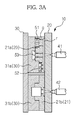
- first, second and third pieces 210a, 220a and 230a are molded to have adhesive passages 241, 242 and 243 filled with the adhesive resin, respectively.
- new pieces 210b, 220b, and 230b may be formed in the same manner as pieces 210a, 220a, and 230a, in order to expedite the manufacturing process.
- the joined body of the present general inventive concept has been described as being used as a blood analyzer, the present general inventive concept may be applied to various products in addition to medical equipment such as a urine analyzer, saliva analyzer, semen analyzer, sweat analyzer, etc. Additionally, the joined body may be applied to any products which involve the analysis of a fluid.
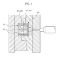
- the above-described pieces may be separately manufactured by injection molding as illustrated in FIGS. 3A - 3F , the pieces may also be manufactured by methods other than injection molding, and then bonded together in accordance with the above-described exemplary embodiment of the present general inventive concept.
- the joined body includes flow passages, through which a fluid flows, in the present general inventive concept, the joined body may include a simple hollow portion formed to be surrounded by the joined body.
Landscapes
- Engineering & Computer Science (AREA)
- Mechanical Engineering (AREA)
- Chemical & Material Sciences (AREA)
- Manufacturing & Machinery (AREA)
- Health & Medical Sciences (AREA)
- Analytical Chemistry (AREA)
- Clinical Laboratory Science (AREA)
- Chemical Kinetics & Catalysis (AREA)
- Hematology (AREA)
- General Health & Medical Sciences (AREA)
- Dispersion Chemistry (AREA)
- Investigating Or Analysing Biological Materials (AREA)
- Injection Moulding Of Plastics Or The Like (AREA)
- Moulds For Moulding Plastics Or The Like (AREA)
- Automatic Analysis And Handling Materials Therefor (AREA)
Applications Claiming Priority (1)
| Application Number | Priority Date | Filing Date | Title |
|---|---|---|---|
| KR1020080078271A KR20100019615A (ko) | 2008-08-11 | 2008-08-11 | 접합체 및 그 제조방법 |
Publications (1)
| Publication Number | Publication Date |
|---|---|
| EP2156889A1 true EP2156889A1 (fr) | 2010-02-24 |
Family
ID=41137771
Family Applications (1)
| Application Number | Title | Priority Date | Filing Date |
|---|---|---|---|
| EP09166913A Withdrawn EP2156889A1 (fr) | 2008-08-11 | 2009-07-31 | Corps assemblé pour la fourniture d'analyses de fluides et son procédé de fabrication |
Country Status (5)
| Country | Link |
|---|---|
| US (1) | US20100035333A1 (fr) |
| EP (1) | EP2156889A1 (fr) |
| JP (1) | JP2010044054A (fr) |
| KR (1) | KR20100019615A (fr) |
| CN (1) | CN101650362A (fr) |
Families Citing this family (4)
| Publication number | Priority date | Publication date | Assignee | Title |
|---|---|---|---|---|
| KR20100019615A (ko) * | 2008-08-11 | 2010-02-19 | 삼성전자주식회사 | 접합체 및 그 제조방법 |
| TWD161734S (zh) * | 2012-06-01 | 2014-07-11 | 三星電子股份有限公司 | 體液檢查盤 |
| TWD157676S (zh) * | 2012-06-01 | 2013-12-01 | 三星電子股份有限公司 | 體液檢查盤的底盤之部分 |
| CN104552747B (zh) * | 2013-10-14 | 2017-02-01 | 玉晶光电(厦门)有限公司 | 光学组件的制造方法 |
Citations (8)
| Publication number | Priority date | Publication date | Assignee | Title |
|---|---|---|---|---|
| JPS63177383A (ja) * | 1987-01-16 | 1988-07-21 | Daicel Chem Ind Ltd | マグネツトクランプ用ハブ及びその取り付け方法 |
| DE19922075A1 (de) | 1999-05-14 | 2000-11-16 | Inst Mikrotechnik Mainz Gmbh | Verfahren zum Verbinden von mikrostrukturierten Werkstücken aus Kunststoff mittels Lösungsmittel |
| EP1396719A1 (fr) * | 2002-07-26 | 2004-03-10 | Enplas Corporation | Assemblage de plaques |
| US20040241381A1 (en) * | 2002-01-31 | 2004-12-02 | Chen Yihfar | Microfluidic structures with circumferential grooves for bonding adhesives and related optical analysis discs |
| WO2005059549A1 (fr) * | 2003-12-18 | 2005-06-30 | Digital Bio Technology | Procede de metallisation d'une microplaquette en plastique |
| WO2007066110A1 (fr) * | 2005-12-06 | 2007-06-14 | Epigem Limited | Systeme et procede permettant d’effectuer une liaison et/ou une fermeture etanche disposant de fines lignes |
| EP1884284A1 (fr) * | 2006-08-04 | 2008-02-06 | Samsung Electronics Co., Ltd. | Unité de soupape à fermeture et appareil de réaction avec soupape à fermeture |
| WO2009006933A1 (fr) * | 2007-07-06 | 2009-01-15 | Agilent Technologies, Inc. | Dispositif microfluidique stratifié, doté d'une structure prévue pour recevoir de la colle destinée à fixer des couches |
Family Cites Families (4)
| Publication number | Priority date | Publication date | Assignee | Title |
|---|---|---|---|---|
| US4267829A (en) * | 1979-04-11 | 1981-05-19 | American Medical Systems, Inc. | Penile prosthesis |
| JP3880930B2 (ja) * | 2002-07-26 | 2007-02-14 | 株式会社エンプラス | プレートの接着部構造 |
| JP2007050463A (ja) * | 2005-08-17 | 2007-03-01 | Konica Minolta Holdings Inc | 流路形成体及び流路形成体の製造方法 |
| KR20100019615A (ko) * | 2008-08-11 | 2010-02-19 | 삼성전자주식회사 | 접합체 및 그 제조방법 |
-
2008
- 2008-08-11 KR KR1020080078271A patent/KR20100019615A/ko not_active Ceased
-
2009
- 2009-06-16 JP JP2009143263A patent/JP2010044054A/ja active Pending
- 2009-06-24 US US12/490,583 patent/US20100035333A1/en not_active Abandoned
- 2009-06-29 CN CN200910150959A patent/CN101650362A/zh active Pending
- 2009-07-31 EP EP09166913A patent/EP2156889A1/fr not_active Withdrawn
Patent Citations (8)
| Publication number | Priority date | Publication date | Assignee | Title |
|---|---|---|---|---|
| JPS63177383A (ja) * | 1987-01-16 | 1988-07-21 | Daicel Chem Ind Ltd | マグネツトクランプ用ハブ及びその取り付け方法 |
| DE19922075A1 (de) | 1999-05-14 | 2000-11-16 | Inst Mikrotechnik Mainz Gmbh | Verfahren zum Verbinden von mikrostrukturierten Werkstücken aus Kunststoff mittels Lösungsmittel |
| US20040241381A1 (en) * | 2002-01-31 | 2004-12-02 | Chen Yihfar | Microfluidic structures with circumferential grooves for bonding adhesives and related optical analysis discs |
| EP1396719A1 (fr) * | 2002-07-26 | 2004-03-10 | Enplas Corporation | Assemblage de plaques |
| WO2005059549A1 (fr) * | 2003-12-18 | 2005-06-30 | Digital Bio Technology | Procede de metallisation d'une microplaquette en plastique |
| WO2007066110A1 (fr) * | 2005-12-06 | 2007-06-14 | Epigem Limited | Systeme et procede permettant d’effectuer une liaison et/ou une fermeture etanche disposant de fines lignes |
| EP1884284A1 (fr) * | 2006-08-04 | 2008-02-06 | Samsung Electronics Co., Ltd. | Unité de soupape à fermeture et appareil de réaction avec soupape à fermeture |
| WO2009006933A1 (fr) * | 2007-07-06 | 2009-01-15 | Agilent Technologies, Inc. | Dispositif microfluidique stratifié, doté d'une structure prévue pour recevoir de la colle destinée à fixer des couches |
Also Published As
| Publication number | Publication date |
|---|---|
| JP2010044054A (ja) | 2010-02-25 |
| KR20100019615A (ko) | 2010-02-19 |
| CN101650362A (zh) | 2010-02-17 |
| US20100035333A1 (en) | 2010-02-11 |
Similar Documents
| Publication | Publication Date | Title |
|---|---|---|
| KR102375602B1 (ko) | 모듈형 유체 칩 및 이를 포함하는 유체 유동 시스템 | |
| JP6927879B2 (ja) | 試料流体分析用の使い捨てカートリッジ | |
| US20100035333A1 (en) | Joined body to provide fluid analysis and manufacturing method thereof | |
| WO2018012429A1 (fr) | Dispositif fluidique, procédé de fabrication d'un dispositif fluidique et robinet pour dispositif fluidique | |
| WO2012014405A1 (fr) | Puce à microcanaux et système de microanalyse | |
| JP4688950B2 (ja) | 回転子積層鉄心の樹脂封止方法 | |
| JP2010158164A (ja) | 回転子積層鉄心の樹脂封止方法 | |
| JP2008054376A (ja) | 回転子積層鉄心の樹脂封止方法 | |
| KR20160003232A (ko) | 랩온어칩 제조 방법 및 시스템 | |
| US20210331163A1 (en) | Microfluidic chip and microfluidic device | |
| US8636033B2 (en) | Microfluidic device initialization method, microfluidic device initialization apparatus and microfluidic device package | |
| JP3780917B2 (ja) | 液体クロマトグラフとその溶離液混合装置 | |
| JP2021020741A (ja) | 無菌流体移送用の流体レシーバ取付具及びそれを製造するための方法 | |
| EP3875574B1 (fr) | Puce microfluidique et dispositif microfluidique | |
| US11130124B2 (en) | Device for surface functionalization and detection | |
| US20090081464A1 (en) | Fine Line Bonding and/or Sealing System and Method | |
| US20250196130A1 (en) | Fluid Device and Method for Manufacturing Fluid Devices | |
| KR101780429B1 (ko) | 정량주입 가능한 바이오칩 | |
| KR102347734B1 (ko) | 미세 채널이 형성된 하부 케이스 상에 오버 몰딩을 통해 상부 커버를 결합한 구조를 갖는 바이오칩 | |
| JP6907152B2 (ja) | マイクロ流路チップとアダプタとの連結構造 | |
| US20170191979A1 (en) | Plastic microchip | |
| US20100310437A1 (en) | Microchip and Method for Manufacturing the Same | |
| JP5291680B2 (ja) | 回転子積層鉄心の樹脂封止方法 | |
| US20240125680A1 (en) | System for dilution in a device and method for manufacturing the device | |
| JP6992824B2 (ja) | 流体デバイス及びシステム |
Legal Events
| Date | Code | Title | Description |
|---|---|---|---|
| PUAI | Public reference made under article 153(3) epc to a published international application that has entered the european phase |
Free format text: ORIGINAL CODE: 0009012 |
|
| AK | Designated contracting states |
Kind code of ref document: A1 Designated state(s): AT BE BG CH CY CZ DE DK EE ES FI FR GB GR HR HU IE IS IT LI LT LU LV MC MK MT NL NO PL PT RO SE SI SK SM TR |
|
| 17P | Request for examination filed |
Effective date: 20100802 |
|
| 17Q | First examination report despatched |
Effective date: 20100824 |
|
| RAP1 | Party data changed (applicant data changed or rights of an application transferred) |
Owner name: SAMSUNG ELECTRONICS CO., LTD. |
|
| STAA | Information on the status of an ep patent application or granted ep patent |
Free format text: STATUS: THE APPLICATION IS DEEMED TO BE WITHDRAWN |
|
| 18D | Application deemed to be withdrawn |
Effective date: 20121123 |