EP2156925A2 - Schleifmaschine - Google Patents
Schleifmaschine Download PDFInfo
- Publication number
- EP2156925A2 EP2156925A2 EP20090168250 EP09168250A EP2156925A2 EP 2156925 A2 EP2156925 A2 EP 2156925A2 EP 20090168250 EP20090168250 EP 20090168250 EP 09168250 A EP09168250 A EP 09168250A EP 2156925 A2 EP2156925 A2 EP 2156925A2
- Authority
- EP
- European Patent Office
- Prior art keywords
- platen
- sander
- power tool
- tool according
- tool body
- Prior art date
- Legal status (The legal status is an assumption and is not a legal conclusion. Google has not performed a legal analysis and makes no representation as to the accuracy of the status listed.)
- Granted
Links
- 230000000717 retained effect Effects 0.000 claims description 2
- 230000001419 dependent effect Effects 0.000 claims 2
- 239000000428 dust Substances 0.000 description 18
- 238000000605 extraction Methods 0.000 description 11
- 238000000034 method Methods 0.000 description 9
- 230000008878 coupling Effects 0.000 description 8
- 238000010168 coupling process Methods 0.000 description 8
- 238000005859 coupling reaction Methods 0.000 description 8
- 238000010276 construction Methods 0.000 description 4
- 239000003082 abrasive agent Substances 0.000 description 2
- 238000001816 cooling Methods 0.000 description 2
- 230000002093 peripheral effect Effects 0.000 description 2
- 241000283973 Oryctolagus cuniculus Species 0.000 description 1
- 244000137852 Petrea volubilis Species 0.000 description 1
- 241000270666 Testudines Species 0.000 description 1
- 239000003086 colorant Substances 0.000 description 1
- 238000004891 communication Methods 0.000 description 1
- 230000009977 dual effect Effects 0.000 description 1
- 239000004744 fabric Substances 0.000 description 1
- 239000000463 material Substances 0.000 description 1
- 230000013011 mating Effects 0.000 description 1
- 239000007769 metal material Substances 0.000 description 1
- 238000012986 modification Methods 0.000 description 1
- 230000004048 modification Effects 0.000 description 1
- NJPPVKZQTLUDBO-UHFFFAOYSA-N novaluron Chemical compound C1=C(Cl)C(OC(F)(F)C(OC(F)(F)F)F)=CC=C1NC(=O)NC(=O)C1=C(F)C=CC=C1F NJPPVKZQTLUDBO-UHFFFAOYSA-N 0.000 description 1
Images




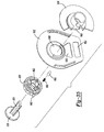

Classifications
-
- B—PERFORMING OPERATIONS; TRANSPORTING
- B24—GRINDING; POLISHING
- B24B—MACHINES, DEVICES, OR PROCESSES FOR GRINDING OR POLISHING; DRESSING OR CONDITIONING OF ABRADING SURFACES; FEEDING OF GRINDING, POLISHING, OR LAPPING AGENTS
- B24B41/00—Component parts such as frames, beds, carriages, headstocks
- B24B41/04—Headstocks; Working-spindles; Features relating thereto
-
- B—PERFORMING OPERATIONS; TRANSPORTING
- B24—GRINDING; POLISHING
- B24B—MACHINES, DEVICES, OR PROCESSES FOR GRINDING OR POLISHING; DRESSING OR CONDITIONING OF ABRADING SURFACES; FEEDING OF GRINDING, POLISHING, OR LAPPING AGENTS
- B24B23/00—Portable grinding machines, e.g. hand-guided; Accessories therefor
- B24B23/02—Portable grinding machines, e.g. hand-guided; Accessories therefor with rotating grinding tools; Accessories therefor
- B24B23/03—Portable grinding machines, e.g. hand-guided; Accessories therefor with rotating grinding tools; Accessories therefor the tool being driven in a combined movement
-
- B—PERFORMING OPERATIONS; TRANSPORTING
- B24—GRINDING; POLISHING
- B24B—MACHINES, DEVICES, OR PROCESSES FOR GRINDING OR POLISHING; DRESSING OR CONDITIONING OF ABRADING SURFACES; FEEDING OF GRINDING, POLISHING, OR LAPPING AGENTS
- B24B23/00—Portable grinding machines, e.g. hand-guided; Accessories therefor
- B24B23/04—Portable grinding machines, e.g. hand-guided; Accessories therefor with oscillating grinding tools; Accessories therefor
-
- B—PERFORMING OPERATIONS; TRANSPORTING
- B24—GRINDING; POLISHING
- B24B—MACHINES, DEVICES, OR PROCESSES FOR GRINDING OR POLISHING; DRESSING OR CONDITIONING OF ABRADING SURFACES; FEEDING OF GRINDING, POLISHING, OR LAPPING AGENTS
- B24B45/00—Means for securing grinding wheels on rotary arbors
- B24B45/006—Quick mount and release means for disc-like wheels, e.g. on power tools
-
- B—PERFORMING OPERATIONS; TRANSPORTING
- B24—GRINDING; POLISHING
- B24B—MACHINES, DEVICES, OR PROCESSES FOR GRINDING OR POLISHING; DRESSING OR CONDITIONING OF ABRADING SURFACES; FEEDING OF GRINDING, POLISHING, OR LAPPING AGENTS
- B24B49/00—Measuring or gauging equipment for controlling the feed movement of the grinding tool or work; Arrangements of indicating or measuring equipment, e.g. for indicating the start of the grinding operation
-
- Y—GENERAL TAGGING OF NEW TECHNOLOGICAL DEVELOPMENTS; GENERAL TAGGING OF CROSS-SECTIONAL TECHNOLOGIES SPANNING OVER SEVERAL SECTIONS OF THE IPC; TECHNICAL SUBJECTS COVERED BY FORMER USPC CROSS-REFERENCE ART COLLECTIONS [XRACs] AND DIGESTS
- Y10—TECHNICAL SUBJECTS COVERED BY FORMER USPC
- Y10T—TECHNICAL SUBJECTS COVERED BY FORMER US CLASSIFICATION
- Y10T29/00—Metal working
- Y10T29/49—Method of mechanical manufacture
- Y10T29/49826—Assembling or joining
-
- Y—GENERAL TAGGING OF NEW TECHNOLOGICAL DEVELOPMENTS; GENERAL TAGGING OF CROSS-SECTIONAL TECHNOLOGIES SPANNING OVER SEVERAL SECTIONS OF THE IPC; TECHNICAL SUBJECTS COVERED BY FORMER USPC CROSS-REFERENCE ART COLLECTIONS [XRACs] AND DIGESTS
- Y10—TECHNICAL SUBJECTS COVERED BY FORMER USPC
- Y10T—TECHNICAL SUBJECTS COVERED BY FORMER US CLASSIFICATION
- Y10T29/00—Metal working
- Y10T29/49—Method of mechanical manufacture
- Y10T29/49826—Assembling or joining
- Y10T29/49863—Assembling or joining with prestressing of part
- Y10T29/4987—Elastic joining of parts
Definitions
- the present invention relates to a sander or other power tool for moving an abrasive medium, having a plurality of platens that can be selectively attached to a common base, preferably without the use of a hand tool.
- Sanders typically have a platen to which an abrasive medium, such as sandpaper, is attached.
- abrasive medium such as sandpaper
- Sanders with removable, differently shaped platens are available to permit the user of the sander to change the platen to one with a shape that is best suited for a given sander task.
- Such removable platens typically are secured to the sander by way of one or more threaded fasteners (e.g., socket head cap screws). These threaded fasteners require the use of tools (e.g., Allen wrenches) to remove them from the sander to thereby decouple the platen from the sander.
- a power tool for moving an abrasive medium comprising a tool body and a drive system housed in the tool body, the drive system including an output member.
- a retaining member may be disposed on the tool body.
- a first platen having a first attachment hub may be selectively coupled with the retaining member in an installed position.
- the first platen may have a first rotatable member that selectively attaches to the output member in a first mode of operation.
- a second platen having a second attachment hub may selectively couple with the retaining member in an installed position.
- the second platen may have a second rotatable member that selectively attaches to the output member in a second mode of operation.
- a mode selector may be disposed on the tool body.
- the mode selector may have a movable member, and preferably has a visible key, for example a pictorial or other symbolic key (e.g. one or more letters and/or numbers and/or images).
- the movable member may be movable between at least a first position that corresponds to a first output member speed and a second position that corresponds to a second output member speed.
- the movable member may be substantially aligned with a first graphic (i.e. symbol or set of symbols) on the visible key that corresponds to the first platen in the first position and second graphic on the visible key that corresponds to the second platen in the second position.
- a second aspect of the invention provides a power tool for moving an abrasive medium, comprising: a tool body; a drive system housed in the tool body and including an output member; a retaining member disposed on the tool body; a first platen having a first attachment hub that selectively couples with the retaining member in an installed position, the first platen having a first rotatable member that selectively attaches to the output member in a first mode of operation; a second platen having a second attachment hub that selectively couples with the retaining member in an installed position, the second platen having a second rotatable member that selectively attaches to the output member in a second mode of operation; and a mode selector disposed on the tool body and having a movable member, wherein the movable member is movable between at least a first position in which the first platen is used in the first mode of operation at a first output member speed and a second position in which the second platen is used (instead of the first platen) in the second
- the movable member preferably is substantially aligned with a first graphic (i.e. symbol or set of symbols) that corresponds to the first platen when the movable member is in the first position, and preferably is substantially aligned with a second graphic that corresponds to the second platen when the movable member is in the second position.
- a first graphic i.e. symbol or set of symbols
- a second graphic that corresponds to the second platen when the movable member is in the second position.
- the first rotatable member of the first platen may be mounted for an orbit having a first offset relative to the output member.
- the second rotatable member of the second platen may be mounted for an orbit having a second offset relative to the output member.
- the first and second offsets may be distinct.
- the first rotatable member may include a first fan having a first counterbalance disposed thereon.
- the second rotatable member may comprise a second fan having a second counterbalance disposed thereon.
- the first and second counterbalances may have distinct masses.
- the first platen may be an orbital platen configured for orbital sanding in the installed position and the second platen may be a random orbit platen configured for random orbit sanding in the installed position.
- the first platen may, for example, comprise a plurality of flexible columns having first ends coupled to the first platen and second ends that are selectively retained by the tool body in the installed position.
- the retaining member may comprise a wireframe that selectively nests in respective grooves defined around each of the first and second attachment hubs respectively in the installed position.
- a button or other actuator may be disposed on the tool body. The actuator may cooperate with the wireframe and be movable to a release position to spread the wireframe and release the wireframe from the respective grooves to exchange between the first and second platens.
- a chamfered annular leading edge is defined on each of the first and second attachment hubs respectively. Movement of a respective first or second platen to the installed position may cause the annular leading edge to spread the wireframe until continued movement toward the installed position causes the wireframe to nest in the respective grooves.
- the tool may include a third platen having a third attachment hub that selectively couples with the retaining member in an installed position.
- the third platen may have a third rotatable member that selectively attaches to the output member in a third mode of operation.
- the first platen may define an iron-shaped profile having a substantially flat first end and a substantially pointed second end.
- the first platen may comprise a dust chute arranged proximate to the substantially pointed second end.
- the third platen may define an iron-shaped profile having a substantially pointed first end and a substantially flat second end.
- the third platen may comprise a dust chute arranged proximate to the substantially flat second end.
- the substantially flat first end of the first platen is aligned with a forward end of the tool in the installed position and the substantially pointed first end of a third platen is aligned with a forward end of the tool in the installed position.
- the tool may comprise a speed control switch that communicates with the mode selector.
- the mode selector may define a rib that cams across an input of the speed control switch upon movement of the mode selector to toggle between the first output member speed and the second output member speed.
- a third aspect of the invention provides a method of selecting an appropriate operating rotational speed and abrading platen (e.g. sanding platen) of a powered abrading tool (e.g. a sander), including providing the tool with a tool body, a drive system and first and second platens.
- the tool body may have a mode selector including a movable member and a visible key, for example a pictorial or other symbolic key (e.g. one or more letters and/or numbers and/or images).
- the drive system can have an output member.
- the method preferably further includes moving the movable member to one of a first position or a second position.
- the first position may correspond to a graphic (i.e.
- the method may further include, mounting one of the first or second platen to the tool body according to the selected first or second position.
- the method may include rotating a dial causing a rib defined on the dial to cam across an input of a speed control switch and change the speed of the output member between a first and second output member speed.
- mounting one of the first or second platens to the tool body may include urging an attachment hub associated with a respective first or second platen into engagement with a wireframe retaining member disposed on the tool body.
- the method further includes, urging the attachment hub into engagement with the wireframe retaining member, such that the wireframe retaining member rides over a chamfered annular leading edge defined on the attachment hub and spreads outwardly until the wireframe retaining member nests at least partially around the selected attachment hub in a groove defined on the selected attachment hub.
- an exemplary abrasive material removal tool is generally indicated by reference numeral 10.
- the abrasive material removal tool hereinafter sander 10
- the sander 10 can further include a drive system 18 that is housed in a cavity defined by the clam shell portions 14 and 16.
- the tool body 12 and the drive system 18 can be conventional in their construction and operation, and as such, need not be discussed in significant detail herein.
- the tool body 12 can further define a dust extraction port 20 ( Fig. 4 ) to which dust can be extracted to a dust chamber 21.
- the drive system 18 can selectively couple with a plurality of platens, collectively referred at reference numeral 22 as will be described in greater detail herein.
- a mode selector 24 can be arranged on a forward portion of the tool body 12.
- the mode selector 24 can include a movable member or dial 26 and a pictorial key 28.
- a base release button 30 can be provided proximate to the mode selector 24.
- a power cord 32 can extend from the tool body 12 to supply electrical current to the sander 10. It is appreciated that while the sander 10 is shown operatively associated with a power cord 32 for alternating current (AC) operation, the sander 10 can also be configured for operation with other power sources, such as direct current (DC) or a pneumatic input.
- AC alternating current
- DC direct current
- the drive system 18 can include an electric motor 36 ( Fig. 4 ) mounted within the tool body 12 and having an output member 38.
- the output member 38 can define a male spline 40.
- a fan (not shown) can be mounted on the output member 38 for rotation therewith.
- the fan can include a plurality of upwardly projecting blades generally arranged to direct air toward the motor 36. In this manner, the upwardly projecting fan blades can operate to generate a cooling air flow when the motor 36 is turned on to help cool the motor 36 during operation of the sander 10.
- a bearing 44 can radially support the output member 38.
- each of the plurality of platens 22 can be releasably connected to the tool body 12 without the use of a hand tool (such as a screwdriver, Allen wrench, etc.).
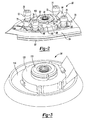
- the exemplary platens 22 can include a finishing sander platen 50, a detail sander platen 52, and a random orbit sander platen 54.
- the detail sander platen 52 can include a releasable finger attachment 56 for detail sander.
- finishing sander platen 50 and detail sander platen 52 are configured for orbital motion while the random orbit sander platen 54 is configured for random orbit motion.
- U.S. Patent Nos. 6,132,300 and 5,885,146 provide examples of abrading tools that provide orbital and random orbit motion. These patents are hereby incorporated by reference as is fully set forth in detail herein.
- the finishing sander platen 50 can define a substantially flat bottom surface 62, a curved upper surface 64, and a peripheral edge with a point 66 that provides the finishing sander platen 50 with an iron-shape.
- the point 66 can be used for sander corners or other areas.
- an abrasive sheet (not shown) can be applied to the flat bottom surface 62 by way of a hook and loop fabric fastener.
- An underside of the abrasive sheet can have a first hook and/or loop surface, which can be attachable to a second hook and/or loop surface (not shown) provided on the flat bottom surface 62 of the finishing sander platen 50.
- a portion 68 of the finishing sander platen 50 can be detachable from the remainder of the finishing sander platen 50.
- the detachable portion 68 can be loosened or completely detached from the finishing sander platen 50 and rotated through 180°, or even replaced, as the edges on either side of the point become worn. Further details of the detachable portion 68 can be found in commonly owned U.S. Patent No. 5,839,949 , which is hereby incorporated by reference as if fully set forth in detail herein.
- the finger attachment portion 56 of the detail sander platen 52 can occupy the space of an otherwise located point 66 (i.e., see finishing sander platen 50).
- the shape and configuration of the finishing sander platen 50 and detail sander platen 52 are substantially equivalent, the finishing sander platen 50 being configured for mounting to the tool body 12 with a flat forward end 70 facing toward the front of the sander 10, whereas the detail sander platen 52, having the finger attachment 56, can be secured to the tool body 12 having the finger attachment 56 being oriented toward the forward end of the sander 10.
- the detail sander platen 52 can also be mounted to the sander 10 without the finger attachment 56.
- the finishing sander platen 50 can further define a plurality of elastomeric legs 72.
- four elastomeric legs 72 are used, one pair toward the front of the sander 10 and another pair disposed toward the rear of the sander 10.
- First ends 76 of the elastomeric legs 72 can be selectively received by mounting hubs 78 defined in the front and rear clam shell portions 14, 16.
- Second ends 80 of the elastomeric legs 72 can be fixedly secured to the finishing sander platen 50 by mounting bosses 79.
- Other configurations may be employed for securing the elastomeric legs 72 between the tool body 12 and the finishing sander platen 50.
- the finishing sander platen 50 can further define a centrally located attachment hub 82 and a chute 84.
- the attachment hub 82 can generally house a rotatable member 88 ( Fig. 6 ).
- the rotatable member 88 can generally be in the form of a fan 90 having a counterweight 92.
- the fan 90 can be configured to direct air through the chute 84 and into the dust extraction port 20.
- the rotatable member 88 can define a mounting hub 93 that aligns for rotation with a female spline 94 that cooperatively receives the male spline 40 of the output member 38 in an installed position.
- the mounting hub 93 can be offset from a central axis 98 of the rotatable member 88.
- the offset can be any suitable distance to provide an orbital motion of the finishing sander platen 50 during operation.
- the offset can be 2mm.
- Other configurations are contemplated.
- other finishing sander platens may be provided having other offsets.
- the attachment hub 82 can define a chamfered annular leading edge 100.
- the attachment hub 82 can further define a groove 102 defined around a cylindrical outboard surface 104.
- a shroud 106 can be defined on the finishing sander platen 50.
- the shroud 106 can generally surround the rotatable member 88.
- the attachment hub 82, the chute 84 and the shroud 106 can be monolithic or integrally formed.
- the detail sander platen 52 can be constructed similarly to the finishing sander platen 50. Therefore, a detailed description of the detail sander platen 52 will not be repeated.
- a chute 84' ( Fig. 1 ) can be arranged proximate to its rearward end (i.e., its flat end 70') for cooperatively aligning with the dust extraction port 20 provided in the tool body 12.
- An attachment hub 82' can house a rotatable member 88' ( Fig. 1 ).
- the random orbit sander platen 54 can generally define a circular platen body 114 having an attachment hub 116.
- the attachment hub 116 can be formed generally equivalent to the attachment hub 82 described above with respect to the finishing sander platen 50.
- a rotatable member 120 Housed within the attachment hub 116 is a rotatable member 120 ( Fig. 7 ).
- the rotatable member 120 can define a similar mounting hub 93', fan 90' and counterweight 92' arrangement as described above with respect to the fan 90, counterweight 92 and mounting hub 93.
- the rotatable member 120 can define a distinct offset (e.g. the mounting hub can be offset from its central axis) as compared to the orbit sander platens 50 and 52, described above.
- the offset can be about 4mm.
- the offset can be 2mm and the orbit can be 4mm.
- each of the platens 22 can define mounting hubs (i.e., 93) that have an offset relative to a central axis of the rotatable member (i.e., 88) for providing a desired offset according to a given application.
- each of the counterweights i.e., 92
- each of the counterweights can be provided with a mass that is specific to a given platen (i.e., 50, 52 or 54).
- the shroud 130 includes a first chute 132 and a second chute 134 formed thereon.
- the shroud 130 can be integrally formed with an attachment hub 136.
- the attachment hub 136 can be formed equivalently to the attachment hubs 82 and 116 described above.
- the shroud 130 having first and second chutes 132 and 134, can operatively align with the dust extraction port 20 in either a forward mounted position (i.e., the pointed end aligned with the front of the sander 10 for an iron-shaped platen) or a rearward mounted position (i.e., the flat end arranged toward the front of the sander 10).
- a plug 140 can be provided in the tool body 12 for aligning with an unused chute 132, 134.
- the plug 140 can be formed of a compliant material and be generally captured by one of, or both of the clam shell housings 14, 16.
- a dust chute connector 144 can be interposed between the functioning chute 132 or 134 and the dust extraction port 20.
- the shroud 130 can be adapted for use with any of the platens 22 disclosed herein.
- the shroud 130 is shown in Fig. 8 operatively associated with a circular random orbit sander platen, whereas the shroud 130 is shown in Figs. 9 and 10 cooperatively with an iron-shaped finishing sander platen.
- the sander 10 can include an attachment assembly 150 for releasably coupling the respective sander platens 22 to the tool body 12.
- the attachment assembly 150 can generally include the button 30, a retaining member or wireframe 152 and a spreader block 154.
- the retaining member 152 is in the form of a wireframe.
- the wireframe 152 can selectively nest with the groove (i.e., groove 102) of a respective attachment hub (i.e., attachment hub 82).
- the attachment assembly 150 can selectively couple with an identified sander platen 22 without the use of a hand tool (such as a screwdriver or Allen key, etc.).
- a hand tool such as a screwdriver or Allen key, etc.
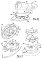
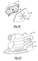
- An exemplary method of attaching the finishing sander platen 50 according to one example of the present teachings will now be described with reference to Figs. 4, 5 and 11-19 . It is appreciated that attaching (and removing) other platens (i.e., 52 or 54) will be carried out similarly.
- a user can generally align the female spline 94 of the rotatable member 88 with the male spline 40 of the output member 38 ( Fig. 4 ).
- a user can align the first ends 76 of the legs 72 with the respective hubs 78 defined in the tool body 12. The user can then urge the tool body 12 downwardly (and/or the finishing sander platen 50 in a direction upward) as viewed in Fig. 11 .
- the wireframe 152 can slidably urge over the chamfered annular leading edge 100 of the attachment hub 82 causing the wireframe 152 to generally spread outwardly until the wireframe 152 "snaps" into the groove 102 (see sequence of Figs. 11-14 ).
- the wireframe 152 can have spring-like characteristics, such that in its relaxed state, the wireframe 152 can occupy a nested position within the groove 102 and therefore retain a respective sander platen 22.
- the wireframe 152 can be formed of a metallic material.
- the attachment assembly 150 and/or the wireframe 152 can be configured differently. During the advancement of the attachment hub 82 toward the tool body 12, the first ends 76 of the legs 72 can nest into the respective hubs 78 defined in the tool body 12.
- a user can push the base release button 30 inwardly (i.e., in a direction leftward as viewed in Fig. 16 ). Movement of the base release button 30 in a direction leftward (i.e., into the tool body 12) can cause the button to slide along the wireframe 152 and therefore urge an intermediate portion of the wireframe 152 to spread radially out of engagement with the groove 102. With the wireframe 152 in a position clear from the groove 102 ( Figs. 16 and 19 ), a user can then pull the finishing sander platen 50 in a direction downward (i.e., in a direction along an axis defined by the female spline 94) and away from the tool body 12.
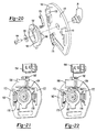
- the mode selector 24 can generally define a control panel 160 that rotatably supports the movable member 26 to a backing plate 162 by way of a threaded fastener 164 and washer 166.
- a rear face 170 of the control panel 160 can define a pair of supports 172 that mount a pair of detent springs 176, respectively.
- the backing plate 162 can define a plurality of depressions 180 formed around its annular surface. As will be described, the detent springs 176 can selectively nest within an aligned pair of depressions 180 to positively locate the movable member 26 at a desired operating location.
- the backing plate 162 can further define a rib 182.
- the rib 182 can be aligned with a toggle bar 184 associated with a speed control switch 188.
- the toggle bar 184 can toggle between a first and second position upon movement of the rib 182 across the toggle bar 184.
- the first and second position can correspond to a first and second speed of the motor 36 (and therefore the output member 38).
- the speed control switch 188 can include a diode 192.
- the speed control switch 188 can be electrically connected to an on/off switch 194 of the sander 10. In n one example, when the speed control switch 188 is moved to the first or “on” position, current bypasses the diode 192 and the sander 10 runs at full speed. When the speed control switch 188 is turned to the second or “off” position, the current is forced through the diode 192 and the voltage is dropped causing the motor 36 (and, as a result, the output member 38 to rotate at a reduced speed).
- the pictorial key 28 of the mode selector 24 can have a first outer zone 200, a second outer zone 202, and a third outer zone 204.
- each of the first, second and third outer zones 200, 202, and 204 can include graphical information, such as photos and/or sketches that correspond to a given sander task.
- the first outer zone 200 can include a graphic with a pictorial representation of the detail sander platen 52.
- the second outer zone 202 can have a graphical representation of the finishing sander platen 50.
- the third outer zone 204 can have a graphical representation of the random orbit sander platen 54.
- each of the outer zones can be color-coded with a distinct color.
- a picture of a turtle can be provided on the first outer zone 200 and a picture of a rabbit can be provided on the third outer zone 204.
- a rotational orientation of the movable member 26 pointing toward the third outer zone 204 can correspond with the first speed and with the toggle bar 184 in the first position, such that the speed control switch 188 is in the "on" position.
- the toggle bar 184 is toggled to the second position (via movement of the rib 182 across the toggle bar 184) corresponding to the speed control switch 188 in the "off" position.
- additional speed settings may be provided according to the outer zones and/or the inner zones (described below). It is contemplated that a potentiometer could be implemented to control speed.
- indicia can be arranged around the pictorial key 28 that correspond to a grit value of sand paper optimized for a given task.
- the pictorial key 28 can have a graphic (e.g. picture, sketch, photograph, etc.) that corresponds to an exemplary article for sander (i.e., a door, a table, a pedestal, etc.).
- the grit value and picture of the article to be sanded can be arranged as a first inner zone 205, a second inner zone 206, a third inner zone 207, a fourth inner zone 208 and a fifth inner zone 209.
- mode selector 24 has been shown and described above in connection to a movable member 26 that rotates around an axis in the form of a dial or pointer, the mode selector can take alternate forms.
- the mode selector 24 can alternatively comprise a lever configured for linear movement or other configurations.
- the sander 210 can generally include a tool body or housing 212 having a pair of clam shell portions 214 and 216.
- the sander 210 can further include a drive system 218 that is housed in a cavity defined by the clam shell portions 214 and 216.
- the tool body 212 and the drive system 218 can be conventional in their construction and operation, and as such, need not be discussed in significant detail herein.
- a mode selector 224 can be rotatably coupled to the tool body 212.
- the sander 210 can be configured for selectively mating with a plurality of platens 222.
- An underside of the mode selector 224 can define a first plurality of notches 225 formed around an annular ring 226.
- the first plurality of notches 225 can cooperatively align with a second plurality of notches 227 defined in the tool body 212.
- the mode selector 224 can further define a pictorial key 228 arranged therearound.
- the pictorial key 228 can define similar graphical representations as described above with respect to the pictorial key 28. In the mode selector 224, according to this example, however, the pictorial key 228 of the mode selector 224 is rotated to align with an arrow 230 provided on the tool body 212.
- the plurality of platens 222 can define a finishing sander platen 250 and a random orbit sander platen 254. Other platens may be provided.
- the detail sander platen 252 can define an attachment hub 260 that includes a series of nubs 262 extending outwardly around a shroud 264 thereof.
- a female spline 268 can be provided on the finishing sander platen 250 and be configured for meshingly engaging a male spline 270 provided on an electric motor 272 of the drive system 218.
- the nubs 262 are configured for slidably aligning and inserting into corresponding first and second notches 225 and 227 defined on the ring 226 of the mode selector 224 and the tool body 212, respectively.
- the first plurality of notches 225 will be rotationally aligned with specific second plurality of notches 227 for accepting the correct platen 222 that corresponds with a given graphic provided on the pictorial key 228 aligning with the arrow 230.
- the random orbit sander platen 254 can include nubs 274 arranged around an attachment hub 276.
- a tongue 280 can extend outwardly adjacent from the attachment hub 276.
- the tongue 280 can be configured to cooperatively nest in a pocket 282 formed on the tool body 212.
- the nubs 274 are located at a radially distinct location around the attachment of 276 as compared to the nubs 262 arranged around the attachment hub 260.
- the nubs 274 cooperatively align with predetermined notches 225 (of the ring 226 of the mode selector 224) and notches 227 (of the tool body 212).
- the rotational orientation of the notches 225, 227 will permit attachment with only the sander platen 222 identified in the pictorial key 228 aligned with the arrow 230. Therefore, attachment of other sander platens 222 is precluded.
- a rotatable member can be provided in the respective attachment hubs 260 and 276 that can be configured to provide a desired offset and/or counterbalance mass according to a given task.
- the platens 222 can be selectively coupled to the sander 210, such as by way of an attachment assembly (see attachment assembly 150 described above), or other methods of attachment.
- the sander 310 can comprise the features as described in herein with respect to other sanders.
- the sander 310 can include a tool body or housing 312 having a pair of clam shell portions 314 and 316.
- the sander 310 can further include a drive system 318 that is housed in a cavity defined by the clam shell portions 314 and 316.
- the tool body 312 and the drive system 318 can be conventional in their construction and operation, and as such, need not be discussed in significant detail herein.
- the drive system 318 can selectively couple with a plurality of platens, collectively referred to a reference 322.
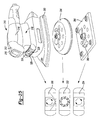
- the sander 310 can include a window 324 that provides viewing access to a wheel 326.
- the wheel 326 can define a pictorial key 328.
- the pictorial key 328 can include a first zone 330, a second zone 332, and a third zone 334.
- the respective zones 330, 332 and 334 can correspond to a graphic (i.e., picture, sketch) that illustrates the shape of a given platen 322 as well as a directional path that such given platen 322 will operate in.
- the platens 322 can include a finishing sander platen 350, a random orbit sander platen 354, and a square footprint detail sander platen 356.
- a finger, or other structure 360, such as shown on the detail sander platen 356 can be provided for rotating the wheels 326 into a rotational position that corresponds to the zone (i.e., 330, 332, or 334) associated with the attached platen 322 being viewed through the window 324.
- a flip key 366 can extend from the output member 338 of the sander 310.
- the flip key 366 can pass through the corresponding opening 370, shown on the finishing sander platen 350 and rotated to a secured position to lock a given platen 322 relative to the tool body 312. While not specifically shown, a similar opening is defined on the other platens 354 and 356.
- the flip key 366 can also be provided on other sanders disclosed herein for securing other platens described herein.
- a sander 410 can comprise the features as described herein with respect to other sanders.
- the sander 410 can be constructed similar to the sanders 10, 210 and 310 described above and also include a dust extraction fan 411 provided in a canister 413 of the tool body 412. Because a dust extraction fan 411 is provided in a canister 413, a plurality of platens (i.e., such as 350, 354 and 356, Fig. 25 ) can include rotatable members tuned for each platen. As such, each rotatable member can define a counterweight mass and offset, but without a fan (i.e., the fan 90 described above in relation with the sander 10).
- the sander 510 can comprise the features as described herein with respect to other sanders.
- the sander 510 can include a tool body or housing 512 having a pair of clam shell portions 514 and 516.
- the sander 510 can further include a drive system 518 that is housed in a cavity defined by the clam shell portions 514 and 516.
- the tool body 512 and the drive system 518 can be conventional in their construction and operation, and as such, need not be discussed in significant detail.
- the drive system 518 can selectively couple with a plurality of platens.
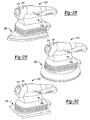
- the platens are shown as a finishing sander platen 520 ( fig. 28 ), a random orbit sander platen 522 ( Fig. 29 ) and a square finishing sander platen 524 ( Fig. 32 ).
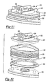
- the sander 510 provides elastomeric bellows 528 for securing a respective platen 520, 522, 524 to the tool body 512.
- the elastomeric bellows 528 is shown coupled between a plate 530 having a fan shroud 532 and an exemplary finishing sander platen 520.
- the fan shroud 532 can generally bound a fan 534 adapted for cooling the motor.
- the plate 530 can further define a dust chute 536 that is configured to exhaust air through a dust extraction chute (such as dust extraction chute 20).
- the elastomeric bellows 528 can couple between a pair of hose clips 560.
- the hose clips 560 can couple on opposite ends to the plate 530 and a securing plate 562.
- the securing plate 562 can define bosses 566 for selectively receiving pegs 568 formed on the finishing sander platen 520.
- the elastomeric bellows 528 provides an enclosure for effective dust extraction.
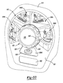
- the mode selector 624 can be operably disposed on a tool body 612 and can include a movable member 630, a control panel 632, a wheel 634 ( Fig. 34 ) and a central hub 636.
- the movable member 630 can be in the form of a dial or knob.
- the movable member 630 can have an indicator 640 formed thereon.
- the control panel 632 can include a pictorial key 642 that includes graphics in a first zone 644a, a second zone 644b, a third zone 644c and a fourth zone 644d.
- the movable member can be configured to rotate, such that the indicator 640 is aligned with a preferred graphic on the pictorial key 642 according to the desired sanding task.
- the control panel 632 can also define an opening 648, a window 650 and a button passage 652.
- the control panel 632 can also define recesses 654 adjacent to the opening 648 for selectively receiving a cap 658 that is biased by a spring 660 in a nested position.
- the biased cap 658 can give a user positive tactile feedback that the movable member 630 is located at the desired position aligned with a respective zone 644a-644d of the pictorial key 642.
- a stem 661 of the central hub 636 locates through an opening 662 formed in the movable member 630, through the opening 648 in the control panel 632 and couples with a hub 663 on the wheel 634.
- the movable member 630, the central hub 636 and the wheel 634 can then collectively rotate relative to the opening 648 of the control panel 632.
- the wheel 634 can include a first image 664a, a second image 664b, a third image 664c, and a fourth image 664d.
- the wheel 634 is fixed for rotation with the movable member 630, such that one of the first through fourth images 664a-664d can be viewable through the window 650.
- the images 664a-664d correspond with the appropriate graphic 644a-644d on the pictorial key 642 according to the desired task identified by the user.
- a user can rotate the movable member 630 from the location shown in Fig. 36 to the location shown in Fig. 37 when it is desired to change the sanding task. While not expressly described here, rotation of the movable member 630 can cooperate with a speed control switch, such as the speed control switch 188 to correspond with first and second speeds of the motor as described above in relation to Figs. 20-22 .
- the movable member 630 is shown rotated to a location, such that the indicator 640 is pointing at the fourth zone 644d.
- a button 653 constructed similar to the button 30 described above is shown extending through the button passage 652. Because the movable member 630 is rotatably fixed with the wheel 634, this position corresponds to the fourth image 664d of the wheel 634 to be viewable through the window 650 of the control panel 632.
- the user can rotate the movable member, such as in a counterclockwise direction until the indicator 640 is pointing at the second zone 644b of the pictorial key 642. In this position, the second image 664b is viewable through the window 650 of the control panel 632.
- the first image 664a of the wheel 634 will be viewable through the window 650 when the indicator 640 is pointing at the first zone 644a of the pictorial key 642.
- the third image 644c of the wheel 634 will be viewable through the window 650 of the control panel 632 when the indicator 640 is pointing at the third zone 644c of the pictorial key 642.
- the respective images 664a-664d can be provided with different colors indicating that some of the selected modes of sanding can include a change in motor speed. It is also appreciated that the mode selector 624 and related features can be configured for operation with any of the sanders described herein.
Landscapes
- Engineering & Computer Science (AREA)
- Mechanical Engineering (AREA)
- Finish Polishing, Edge Sharpening, And Grinding By Specific Grinding Devices (AREA)
Priority Applications (1)
| Application Number | Priority Date | Filing Date | Title |
|---|---|---|---|
| EP16160202.4A EP3050672B1 (de) | 2008-08-20 | 2009-08-20 | Schleifmaschine |
Applications Claiming Priority (2)
| Application Number | Priority Date | Filing Date | Title |
|---|---|---|---|
| US9041708P | 2008-08-20 | 2008-08-20 | |
| US12/540,189 US8172642B2 (en) | 2008-08-20 | 2009-08-12 | Multi-sander |
Related Child Applications (2)
| Application Number | Title | Priority Date | Filing Date |
|---|---|---|---|
| EP16160202.4A Division EP3050672B1 (de) | 2008-08-20 | 2009-08-20 | Schleifmaschine |
| EP16160202.4A Division-Into EP3050672B1 (de) | 2008-08-20 | 2009-08-20 | Schleifmaschine |
Publications (3)
| Publication Number | Publication Date |
|---|---|
| EP2156925A2 true EP2156925A2 (de) | 2010-02-24 |
| EP2156925A3 EP2156925A3 (de) | 2013-09-04 |
| EP2156925B1 EP2156925B1 (de) | 2016-05-18 |
Family
ID=41328574
Family Applications (2)
| Application Number | Title | Priority Date | Filing Date |
|---|---|---|---|
| EP09168250.0A Not-in-force EP2156925B1 (de) | 2008-08-20 | 2009-08-20 | Schleifmaschine |
| EP16160202.4A Not-in-force EP3050672B1 (de) | 2008-08-20 | 2009-08-20 | Schleifmaschine |
Family Applications After (1)
| Application Number | Title | Priority Date | Filing Date |
|---|---|---|---|
| EP16160202.4A Not-in-force EP3050672B1 (de) | 2008-08-20 | 2009-08-20 | Schleifmaschine |
Country Status (4)
| Country | Link |
|---|---|
| US (6) | US8172642B2 (de) |
| EP (2) | EP2156925B1 (de) |
| CN (1) | CN201579686U (de) |
| CA (1) | CA2676053C (de) |
Cited By (2)
| Publication number | Priority date | Publication date | Assignee | Title |
|---|---|---|---|---|
| EP2607016A3 (de) * | 2011-12-21 | 2014-09-03 | Makita Corporation | Schleifmaschine |
| EP2548702A3 (de) * | 2011-07-18 | 2018-05-09 | Black & Decker Inc. | Mehrkopf-Elektrowerkzeug mit Umkehrsperrfunktion |
Families Citing this family (34)
| Publication number | Priority date | Publication date | Assignee | Title |
|---|---|---|---|---|
| US8172642B2 (en) * | 2008-08-20 | 2012-05-08 | Black & Decker Inc. | Multi-sander |
| DE102010012024B4 (de) * | 2010-03-19 | 2015-05-28 | Festool Gmbh | Handwerkzeugmaschine mit einem Zwangsrotation-Exzentergetriebe |
| DE102010033602B4 (de) * | 2010-08-06 | 2021-11-18 | Mafell Ag | Schleifsystem |
| US9776315B2 (en) | 2011-11-11 | 2017-10-03 | Black & Decker Inc. | Power tool having interchangeable tool heads with an independent accessory switch |
| US10399218B2 (en) * | 2011-12-19 | 2019-09-03 | Carine Elen | Motorized scrubbing, buffing, and polishing tool |
| WO2013093619A2 (en) * | 2011-12-19 | 2013-06-27 | Carine Elen | Motorized scrubbing, buffing, and polishing tool |
| US9393658B2 (en) | 2012-06-14 | 2016-07-19 | Black & Decker Inc. | Portable power tool |
| DE102012210893B4 (de) | 2012-06-26 | 2026-02-19 | Robert Bosch Gmbh | Handschleifmaschine mit einer Schwingplatte |
| USD734116S1 (en) * | 2012-06-27 | 2015-07-14 | Kwai Sun Oliver Wong | Replacement head for a hand-held sanding implement |
| US9032576B2 (en) * | 2012-12-19 | 2015-05-19 | Newton Medical, Llc | Apparatus with elliptical movement for microdermabrasion and topical delivery of treatments |
| US9877629B2 (en) | 2013-02-08 | 2018-01-30 | Techtronic Industries Co. Ltd. | Battery-powered cordless cleaning system |
| US9956677B2 (en) | 2013-05-08 | 2018-05-01 | Black & Decker Inc. | Power tool with interchangeable power heads |
| CN104275630A (zh) * | 2013-07-12 | 2015-01-14 | 南京德朔实业有限公司 | 手持式砂光机 |
| US9387578B2 (en) | 2013-10-28 | 2016-07-12 | Black & Decker Inc. | Handle arrangement for sander |
| USD741557S1 (en) | 2014-01-15 | 2015-10-20 | Milwaukee Electric Tool Corporation | Dust collector |
| USD742081S1 (en) | 2014-01-15 | 2015-10-27 | Milwaukee Electric Tool Corporation | Dust collector |
| US9751176B2 (en) | 2014-05-30 | 2017-09-05 | Black & Decker Inc. | Power tool accessory attachment system |
| US10286516B2 (en) * | 2015-10-15 | 2019-05-14 | Makita Corporation | Polishers |
| WO2018001284A1 (zh) | 2016-06-28 | 2018-01-04 | 苏州宝时得电动工具有限公司 | 砂光机及其操作方法和工作底板的拆装方法 |
| US10020629B1 (en) * | 2017-07-13 | 2018-07-10 | Adam Michael Wise | Hotstick tool for assisting linemen tapping high power lines using wedge tap connectors |
| CN113043133B (zh) * | 2017-08-04 | 2022-10-14 | 苏州宝时得电动工具有限公司 | 打磨工具 |
| CN107855926A (zh) * | 2017-12-07 | 2018-03-30 | 金翰阳科技(大连)股份有限公司 | 打磨机床工件交换装置 |
| CN209868288U (zh) * | 2018-01-15 | 2019-12-31 | 苏州宝时得电动工具有限公司 | 打磨工具 |
| USD910396S1 (en) * | 2018-09-24 | 2021-02-16 | 3M Innovative Properties Company | Attachment for a sanding device |
| CN110919555B (zh) * | 2019-12-19 | 2024-04-16 | 宋京新 | 一种外转内冷可互换电镀杯型砂轮 |
| US20210196322A1 (en) * | 2019-12-27 | 2021-07-01 | Candace Fletcher | Foot Sander Assembly |
| CN220631979U (zh) | 2020-07-09 | 2024-03-22 | 米沃奇电动工具公司 | 与真空清洁器一起使用的附件 |
| USD974869S1 (en) | 2021-03-08 | 2023-01-10 | Photonix Corp | Cutting tool |
| US20230017671A1 (en) * | 2021-07-14 | 2023-01-19 | Milwaukee Electric Tool Corporation | Quarter sheet sander |
| US12318885B2 (en) * | 2021-09-03 | 2025-06-03 | X'pole Precision Tools Inc. | Sanding disc stabilizing structure of orbital sander |
| TWI850612B (zh) * | 2021-12-17 | 2024-08-01 | 財團法人工業技術研究院 | 使用能量束的表面加工設備及表面加工方法 |
| CN114888680B (zh) * | 2022-05-09 | 2023-06-06 | 常州赛迪工具有限公司 | 一种砂光机快换底板及多功能砂光机 |
| JP2024116526A (ja) | 2023-02-16 | 2024-08-28 | 株式会社マキタ | サンダ用のパッド、および、パッド |
| CN116175343A (zh) * | 2023-03-22 | 2023-05-30 | 慈溪市华吉电器有限公司 | 一种磨床 |
Citations (3)
| Publication number | Priority date | Publication date | Assignee | Title |
|---|---|---|---|---|
| US5839949A (en) | 1995-10-04 | 1998-11-24 | Black & Decker Inc. | Sander with multiple-layered platen |
| US5885146A (en) | 1995-12-06 | 1999-03-23 | Black & Decker Inc. | Oscillating hand tool |
| US6132300A (en) | 1994-07-26 | 2000-10-17 | Black & Decker Inc. | Dual function oscillating tool |
Family Cites Families (168)
| Publication number | Priority date | Publication date | Assignee | Title |
|---|---|---|---|---|
| US1965669A (en) | 1932-08-12 | 1934-07-10 | James C Robb | Portable electric tool |
| US2713271A (en) | 1951-07-17 | 1955-07-19 | Mall Tool Company | Motion converting means |
| US2898616A (en) | 1955-01-28 | 1959-08-11 | Kay Busser | Brush holder for waxing and polishing machines |
| US2795901A (en) * | 1955-07-28 | 1957-06-18 | Bruce H Mosbacher | Rubbing and abrading machines |
| US2893175A (en) * | 1957-12-19 | 1959-07-07 | American Lincoln Corp | Surfacing machine |
| US3525912A (en) | 1966-03-28 | 1970-08-25 | Scovill Manufacturing Co | Selectable power source for a motor driven appliance |
| US3390412A (en) * | 1966-06-22 | 1968-07-02 | Sunbeam Corp | Shoe polisher |
| JPS4812852Y1 (de) | 1968-01-20 | 1973-04-07 | ||
| US3533193A (en) * | 1968-11-25 | 1970-10-13 | Singer Co | Dual motion pad sanders |
| DE1938350A1 (de) * | 1969-07-29 | 1971-02-11 | Stoll Kg Kurt | Handschleifgeraet |
| US3724237A (en) | 1971-06-07 | 1973-04-03 | Black & Decker Mfg Co | Attachment coupling for power tool |
| US3747594A (en) | 1971-11-19 | 1973-07-24 | Dormeyer A F Mfg Co | Portable electric appliance |
| US3761663A (en) | 1971-12-08 | 1973-09-25 | Cutler Hammer Inc | Trigger switch with selective two-position trigger-depression limiting means |
| US3759336A (en) | 1972-01-21 | 1973-09-18 | D Marcovitz | Interchangeable power operated tools |
| US3793776A (en) | 1972-07-21 | 1974-02-26 | Black & Decker Mfg Co | Double insulated portable sander |
| US3841416A (en) * | 1972-08-15 | 1974-10-15 | Black & Decker Mfg Co | Portable jig-saw and spindle sander |
| DE2316286A1 (de) * | 1973-03-31 | 1974-10-17 | Bosch Gmbh Robert | Schwingschleifer |
| US3908139A (en) | 1974-06-10 | 1975-09-23 | Singer Co | Portable power tools |
| US3973179A (en) | 1974-08-23 | 1976-08-03 | The Black And Decker Manufacturing Company | Modular cordless tools |
| US3952239A (en) | 1974-08-23 | 1976-04-20 | The Black And Decker Manufacturing Company | Modular cordless tools |
| US3899852A (en) | 1974-08-23 | 1975-08-19 | Singer Co | Spindle drive assembly for a surface-treating machine |
| US4091880A (en) | 1975-10-17 | 1978-05-30 | Concept Inc. | Surgical wire inserter apparatus |
| US4050528A (en) | 1975-09-05 | 1977-09-27 | Concept, Inc. | Wire inserter |
| US4103511A (en) | 1976-10-04 | 1978-08-01 | Firma Kress Elektrik Gmbh & Co. | Connecting arrangement for a machine tool |
| USRE30680E (en) | 1976-10-04 | 1981-07-21 | Firma Kress Elektrik Gmbh & Co. | Connecting arrangement for a machine tool |
| US4052824A (en) * | 1976-11-29 | 1977-10-11 | Hutchins Manufacturing Company | Abrading tool suction system |
| US4125339A (en) | 1977-06-29 | 1978-11-14 | Pittinger Sr Charles B | Releasably interlocked, assymmetrical, lugged flange joint with fixed relative orientation |
| DE2748502B2 (de) | 1977-10-28 | 1979-08-30 | Licentia Patent-Verwaltungs-Gmbh, 6000 Frankfurt | Elektrowerkzeug mit elektrischer Drehzahlerfassung mittels Tachogenerator |
| DE2852327A1 (de) | 1978-12-04 | 1980-06-26 | Robert Wolff | Anschraubbarer einspannhals fuer halslose elektrische handbohrmaschinen |
| IT1163681B (it) | 1979-06-28 | 1987-04-08 | Star Utensili Elett | Generatrice tachimetrica |
| DE2933355A1 (de) | 1979-08-17 | 1981-03-26 | Scintilla Ag, Solothurn | Elektrohandwerkzeug |
| ATE12862T1 (de) | 1980-01-28 | 1985-05-15 | Black & Decker Inc | Verfahren und steuerung zur temperaturueberwachung eines elektrischen motors. |
| US4307325A (en) | 1980-01-28 | 1981-12-22 | Black & Decker Inc. | Digital control system for electric motors in power tools and the like |
| US4304071A (en) | 1980-02-08 | 1981-12-08 | Poma 2.000 S.A | Safety device for sliding doors |
| DE3012637C2 (de) | 1980-04-01 | 1984-06-28 | Metabowerke GmbH & Co, 7440 Nürtingen | Elektromotorisch angetriebenes Handwerkzeug mit einer Rutschkupplung |
| US4504769A (en) | 1980-10-28 | 1985-03-12 | Makita Electric Works, Ltd. | Electrically-powered tool |
| EP0086114A1 (de) | 1982-02-10 | 1983-08-17 | Hitachi Koki Co., Ltd. | Elektrisches Werkzeug mit Geschwindigkeitsregelschaltung |
| US4513381A (en) * | 1982-06-07 | 1985-04-23 | The Singer Company | Speed regulator for power tool |
| JPS59163608A (ja) * | 1983-03-08 | 1984-09-14 | Hitachi Koki Co Ltd | ジグソ− |
| FR2568377A1 (fr) | 1984-07-25 | 1986-01-31 | Jouan | Capteur de vitesse a effet hall incorpore dans une machine tournante |
| JPS6161761A (ja) * | 1984-08-29 | 1986-03-29 | Makita Denki Seisakusho:Kk | コ−ドレス研摩機 |
| DE3518984A1 (de) * | 1985-05-25 | 1986-11-27 | Festo KG, 7300 Esslingen | Ausgewuchteter schwingschleifer |
| DE3538225C2 (de) | 1985-10-26 | 1997-08-14 | Wilo Gmbh | Kreiselpumpe oder Lüfter |
| GB8529006D0 (en) | 1985-11-25 | 1986-01-02 | Highgate D J | Hydrophilic materials |
| US4728942A (en) | 1985-12-09 | 1988-03-01 | The Scott & Fetzer Company | Self-powered rotation indicator |
| DE3615799C2 (de) * | 1986-05-10 | 1994-10-13 | Bosch Gmbh Robert | Exzenterschleifer mit einer Vorrichtung zum Verändern der Schleifbewegung |
| US4834596A (en) | 1987-11-23 | 1989-05-30 | T.M. Smith Tool International Corporation | Quick change spindle adaptor for tool holder |
| US4871629A (en) | 1988-02-04 | 1989-10-03 | Black & Decker Inc. | Latching arrangement for battery packs |
| US4835410A (en) | 1988-02-26 | 1989-05-30 | Black & Decker Inc. | Dual-mode corded/cordless system for power-operated devices |
| US4835409A (en) | 1988-02-26 | 1989-05-30 | Black & Decker Inc. | Corded/cordless dual-mode power-operated device |
| US4827552A (en) | 1988-03-14 | 1989-05-09 | Better Health Concepts, Inc. | Rotary electric toothbrush |
| US5018411A (en) | 1988-07-03 | 1991-05-28 | Padura Nathan P | Multiple-head tool |
| US4962681A (en) | 1988-11-09 | 1990-10-16 | Yang Tai Her | Modular manual electric appliance |
| DE3906549A1 (de) * | 1989-03-02 | 1990-09-06 | Bosch Gmbh Robert | Exzenterschleifer |
| US5018314A (en) * | 1989-06-08 | 1991-05-28 | Makita Electric Works, Ltd. | Sander |
| CN2074697U (zh) | 1989-10-30 | 1991-04-10 | 宋文广 | 带有负载指示器的手持磨光机 |
| US5128783A (en) | 1990-01-31 | 1992-07-07 | Ois Optical Imaging Systems, Inc. | Diffusing/collimating lens array for a liquid crystal display |
| US4995148A (en) | 1990-03-30 | 1991-02-26 | Imta | Robotically controlled multi-task end effector |
| US5033552A (en) | 1990-07-24 | 1991-07-23 | Hu Cheng Te | Multi-function electric tool |
| US5241053A (en) | 1990-09-05 | 1993-08-31 | Takeda Chemical Industries, Ltd. | Fused proteins comprising glycoprotein gD of HSV-1 and LTB |
| DE59101383D1 (de) | 1991-01-16 | 1994-05-19 | Fein C & E | Tragbare Schleifmaschine mit Schnellspanneinrichtung. |
| US5149230A (en) | 1991-03-04 | 1992-09-22 | Nett Daniel R | Rotating dual attachment receptacle apparatus tool |
| DE4113641A1 (de) | 1991-04-26 | 1992-10-29 | Bosch Gmbh Robert | Handwerkzeugmaschine |
| DE4137385C2 (de) | 1991-11-14 | 1993-11-18 | Hilti Ag | Drehzahlregeleinrichtung für ein handgehaltenes Elektrowerkzeug und Verfahren zu deren Herstellung |
| DE4233729A1 (de) | 1992-10-07 | 1994-04-14 | Bosch Gmbh Robert | Exzentertellerschleifer mit Schleiftellerbremse |
| DE4223107A1 (de) | 1992-07-14 | 1994-01-20 | Bosch Gmbh Robert | Flächenschleifmaschine |
| US5398457A (en) * | 1992-12-11 | 1995-03-21 | Updegrave; Scott A. | Edge and corner sanding attachment |
| DE4300037C1 (de) | 1993-01-02 | 1994-04-21 | Raymond A & Cie | Lösbare Steckverbindung |
| US5626510A (en) | 1993-02-04 | 1997-05-06 | Robert Bosch Gmbh | Power tool for surface treatment |
| DE4303044A1 (de) | 1993-02-04 | 1994-08-11 | Bosch Gmbh Robert | Handwerkzeugmaschine zur Flächenbearbeitung |
| DE4314799C2 (de) * | 1993-05-05 | 1995-04-13 | Fein C & E | Elektrowerkzeug |
| GB9320181D0 (en) | 1993-09-30 | 1993-11-17 | Black & Decker Inc | Improvements in and relating to power tools |
| US5392568A (en) | 1993-12-22 | 1995-02-28 | Black & Decker Inc. | Random orbit sander having braking member |
| DE59410331D1 (de) * | 1994-02-03 | 2003-11-27 | Bosch Gmbh Robert | Handwerkzeugmaschine zur Flächenbearbeitung |
| US5580302A (en) | 1994-02-28 | 1996-12-03 | Black & Decker Inc. | Random orbit sander having air directing baffle |
| US5421053A (en) | 1994-04-28 | 1995-06-06 | Aar Corp. | Removable brush coupling |
| US5490683A (en) | 1994-07-27 | 1996-02-13 | Mednext Inc. | Tool shaft coupler |
| US6270087B1 (en) | 1994-07-27 | 2001-08-07 | Mednext, Inc. | Tool shaft coupler |
| US6062575A (en) | 1994-07-27 | 2000-05-16 | Mednext, Inc. | Tool shaft coupler |
| US5759094A (en) | 1995-02-09 | 1998-06-02 | Porter-Cable Corporation | In-line detail sander |
| DE19617572A1 (de) | 1996-05-02 | 1997-11-13 | Bosch Gmbh Robert | Elektrische Handschleifmaschine |
| US5715156A (en) | 1996-06-24 | 1998-02-03 | Yilmaz; G. George | Method and apparatus for providing AC or DC power for battery powered tools |
| DE19731949C2 (de) | 1996-07-26 | 2001-04-26 | Makita Corp | Schraubenfördereinrichtung in einem kontinuierlich arbeitenden Schraubendreherwerkzeug |
| US5888200A (en) | 1996-08-02 | 1999-03-30 | Stryker Corporation | Multi-purpose surgical tool system |
| US5771516A (en) | 1996-08-26 | 1998-06-30 | Huang; Chen Shu-Hsia | Exchangeable power hand tool |
| JPH10286772A (ja) | 1997-04-09 | 1998-10-27 | Nikon Corp | 研磨工具および研削工具 |
| GB9718312D0 (en) | 1997-08-30 | 1997-11-05 | Black & Decker Inc | Power tool |
| GB9718337D0 (en) | 1997-08-30 | 1997-11-05 | Black & Decker Inc | Power tool |
| GB9718305D0 (en) | 1997-08-30 | 1997-11-05 | Black & Decker Inc | Power tool |
| GB9718336D0 (en) | 1997-08-30 | 1997-11-05 | Black & Decker Inc | Power tool |
| GB9720721D0 (en) | 1997-10-01 | 1997-11-26 | Black & Decker Inc | Power Tool |
| DE69805150T2 (de) | 1997-12-03 | 2002-12-12 | Ykk Corp., Tokio/Tokyo | Werkzeughalter für tragbare oszillierende Schleifmaschine |
| GB9802587D0 (en) | 1998-02-07 | 1998-04-01 | Black & Decker Inc | Power tool |
| GB9804472D0 (en) | 1998-03-04 | 1998-04-29 | Black & Decker Inc | A switch lock-off mechanism |
| US6062960A (en) * | 1998-04-27 | 2000-05-16 | Ryobi North America, Inc. | Orbital tool |
| US5947804A (en) * | 1998-04-27 | 1999-09-07 | Ryobi North America, Inc. | Adjustable eccentricity orbital tool |
| GB9809030D0 (en) | 1998-04-29 | 1998-06-24 | Black & Decker Inc | Powered oscillating hand tool |
| DE19820873A1 (de) | 1998-05-09 | 1999-11-11 | Bosch Gmbh Robert | Elektrohandwerkzeugmaschine, insbesondere Handschleifmaschine |
| US6039126A (en) | 1998-05-15 | 2000-03-21 | Hsieh; An-Fu | Multi-usage electric tool with angle-changeable grip |
| US6126370A (en) | 1998-07-22 | 2000-10-03 | Black & Decker Inc. | Removable tool holder |
| JP2000176818A (ja) | 1998-12-21 | 2000-06-27 | Ykk Corp | 研磨布紙の固定具 |
| US6296065B1 (en) | 1998-12-30 | 2001-10-02 | Black & Decker Inc. | Dual-mode non-isolated corded system for transportable cordless power tools |
| US7828630B2 (en) | 1999-02-08 | 2010-11-09 | Black & Decker Inc. | Tool body |
| US6243276B1 (en) | 1999-05-07 | 2001-06-05 | S-B Power Tool Company | Power supply system for battery operated devices |
| AU5701200A (en) | 1999-07-02 | 2001-01-22 | Petrus Besselink | Reinforced expandable cage |
| US6244933B1 (en) | 1999-07-07 | 2001-06-12 | Wolfgang Morkvenas | Random orbital finishing apparatus |
| US6104162A (en) | 1999-09-11 | 2000-08-15 | Sainsbury; Simon R. | Method and apparatus for multi-power source for power tools |
| US6286609B1 (en) | 1999-12-10 | 2001-09-11 | Black & Decker Inc. | AC/DC chopper for power tool |
| US6237698B1 (en) | 1999-12-10 | 2001-05-29 | Black & Decker Inc. | Terminal protection system for portable power tools |
| GB0005897D0 (en) | 2000-03-10 | 2000-05-03 | Black & Decker Inc | Power tool |
| GB0005821D0 (en) | 2000-03-10 | 2000-05-03 | Black & Decker Inc | Coupling method |
| GB0005937D0 (en) | 2000-03-10 | 2000-05-03 | Black & Decker Inc | Interlock mechanism |
| GB0005822D0 (en) | 2000-03-10 | 2000-05-03 | Black & Decker Inc | Coupling mechanism |
| JP2001300867A (ja) | 2000-04-21 | 2001-10-30 | Makita Corp | 電動工具用アダプタ |
| US6523214B1 (en) * | 2000-06-14 | 2003-02-25 | Richard A. Kaiser | Quick mount attachment for rotary finishing tool |
| NL1015488C2 (nl) * | 2000-06-21 | 2001-12-28 | Skil Europ Bv | Vlakschuurmachine met verwisselbaar deel van schuurzool. |
| US6613089B1 (en) | 2000-10-25 | 2003-09-02 | Sdgi Holdings, Inc. | Laterally expanding intervertebral fusion device |
| US6573621B2 (en) | 2000-12-01 | 2003-06-03 | S-B Power Tool Company | AC/DC power supply system for power tools |
| DE10104993A1 (de) * | 2001-02-03 | 2002-08-22 | Bosch Gmbh Robert | Handwerkzeugmaschine zum Schleifen, Polieren oder dergleichen |
| CN1381336A (zh) | 2001-04-17 | 2002-11-27 | 上海星特浩企业有限公司 | 交、直流可互换多用途组合工具 |
| US6601621B2 (en) | 2001-04-18 | 2003-08-05 | Black & Decker Inc. | Portable Power Planer |
| DE10124971B4 (de) | 2001-05-21 | 2013-06-20 | Hilti Aktiengesellschaft | Schnellspanneinrichtung für eine Kreissäge |
| GB2380151B (en) | 2001-07-20 | 2004-09-22 | Black & Decker Inc | Oscillating hand tool |
| GB2377662B (en) | 2001-07-20 | 2004-09-22 | Black & Decker Inc | Oscillating hand tool |
| US6494916B1 (en) | 2001-07-30 | 2002-12-17 | Biomed Solutions, Llc | Apparatus for replacing musculo-skeletal parts |
| US20030097178A1 (en) | 2001-10-04 | 2003-05-22 | Joseph Roberson | Length-adjustable ossicular prosthesis |
| US6889878B2 (en) * | 2001-11-08 | 2005-05-10 | Armament Systems And Procedures, Inc. | Baton carrier |
| US7048617B1 (en) | 2002-05-17 | 2006-05-23 | Spiva Neal A | Method and apparatus for smoothing unfinished surfaces |
| US7653963B2 (en) | 2002-11-12 | 2010-02-02 | Black & Decker Inc. | AC/DC hand portable wet/dry vacuum having improved portability and convenience |
| US20040220672A1 (en) | 2003-05-03 | 2004-11-04 | Shadduck John H. | Orthopedic implants, methods of use and methods of fabrication |
| US7270910B2 (en) | 2003-10-03 | 2007-09-18 | Black & Decker Inc. | Thermal management systems for battery packs |
| DE102004003203A1 (de) | 2004-01-22 | 2005-08-11 | Robert Bosch Gmbh | Elektro-Handwerkzeug mit optimiertem Arbeitsbereich |
| US20050221738A1 (en) | 2004-04-06 | 2005-10-06 | Cooper Vincent P | Orbital sander with vertical handle |
| CN201030495Y (zh) | 2004-04-13 | 2008-03-05 | 布莱克和戴克公司 | 低外形电动磨光机 |
| US7114824B2 (en) | 2004-05-03 | 2006-10-03 | Picone Products, Inc. | Multi-functional tool with interchangeable adjustable wrench head unit |
| US20060019585A1 (en) | 2004-07-26 | 2006-01-26 | Zayat Charles D | Device for circular grinding, sanding and stripping tools to attach to any power drive |
| US7220174B2 (en) | 2004-09-29 | 2007-05-22 | Black & Decker Inc. | Drywall sander |
| US7198559B2 (en) | 2004-12-23 | 2007-04-03 | Black & Decker, Inc. | Modular sander-casing architecture |
| US7384173B2 (en) | 2004-12-30 | 2008-06-10 | 3M Innovative Properties Company | Brightness enhancement article |
| US7235005B2 (en) | 2005-03-24 | 2007-06-26 | Black & Decker Inc. | Belt sander |
| JP2006321043A (ja) | 2005-05-17 | 2006-11-30 | Milwaukee Electric Tool Corp | 動力工具、バッテリ、充電器、およびそれらを動作させる方法 |
| DE102005045310B3 (de) * | 2005-09-16 | 2007-03-22 | Alfred Kärcher Gmbh & Co. Kg | Fahrbare Bodenreinigungsmaschine |
| US7775855B2 (en) * | 2005-12-29 | 2010-08-17 | 3M Innovative Properties Company | Sanding tool with rotatable handle |
| ATE448040T1 (de) | 2006-03-01 | 2009-11-15 | Robatti Aps | Revolverkopf-hand- bohrmaschine/antriebsvorrichtung |
| US7926141B2 (en) | 2006-08-15 | 2011-04-19 | Umagination Labs, L.P. | Systems and methods of a gutter cleaning system |
| US7743683B2 (en) | 2006-08-15 | 2010-06-29 | Umagination Labs, L.P. | Systems and methods of a power tool system with interchangeable functional attachments powered by a direct rotational drive |
| US7913345B2 (en) | 2006-08-15 | 2011-03-29 | Umagination Labs, L.P. | Systems and methods of a power tool system with interchangeable functional attachments |
| US7713110B2 (en) * | 2006-09-05 | 2010-05-11 | Dynabrade, Inc. | Locking random orbital dual-action head assembly |
| DE102006045157B4 (de) | 2006-09-25 | 2020-06-18 | Robert Bosch Gmbh | Handwerkzeugmaschine |
| DE102006048315A1 (de) | 2006-10-12 | 2008-04-17 | Robert Bosch Gmbh | Handwerkzeugmaschine, insbesondere elektrische Schere |
| US7568867B2 (en) | 2006-10-18 | 2009-08-04 | Bryan Steve M | Air driven spindle assembly |
| US7719230B2 (en) | 2006-10-27 | 2010-05-18 | Snap-On Incorporated | Kit of power tools |
| US7609025B2 (en) | 2006-11-03 | 2009-10-27 | Snap-On Incorporated | Kit of power tools |
| US7722435B2 (en) * | 2007-06-13 | 2010-05-25 | Black & Decker Inc. | Sander |
| US7825615B2 (en) | 2007-10-16 | 2010-11-02 | Glj, Llc | Intelligent motorized appliances with multiple power sources |
| US7770660B2 (en) | 2007-11-21 | 2010-08-10 | Black & Decker Inc. | Mid-handle drill construction and assembly process |
| US8172650B2 (en) * | 2008-03-18 | 2012-05-08 | Paul W. Huber | Automatic shift dual-action tool |
| US8172642B2 (en) | 2008-08-20 | 2012-05-08 | Black & Decker Inc. | Multi-sander |
| US7736216B2 (en) * | 2008-08-20 | 2010-06-15 | Black & Decker Inc. | Sander having removable platen |
| CN101992456B (zh) | 2009-08-11 | 2013-02-06 | 泉峰(中国)贸易有限公司 | 电动工具 |
| CN102049762B (zh) | 2009-10-28 | 2012-08-22 | 南京德朔实业有限公司 | 一种电动榔头 |
| CN201565933U (zh) | 2009-10-30 | 2010-09-01 | 南京德朔实业有限公司 | 一种电动榔头 |
| CN201525004U (zh) | 2009-11-04 | 2010-07-14 | 南京德朔实业有限公司 | 一种电动榔头 |
| CN201565934U (zh) | 2009-11-06 | 2010-09-01 | 南京德朔实业有限公司 | 一种电动榔头 |
| CN201525005U (zh) | 2009-11-05 | 2010-07-14 | 南京德朔实业有限公司 | 一种电动榔头 |
| CN201659545U (zh) | 2009-11-09 | 2010-12-01 | 南京德朔实业有限公司 | 一种电动榔头 |
| US20110121782A1 (en) | 2009-11-23 | 2011-05-26 | Marsh Douglas G | Powering a Cordless Drill from AC Line Power |
| EP2674259B1 (de) | 2009-12-18 | 2017-11-01 | Techtronic Power Tools Technology Limited | Multifunktionswerkzeugsystem |
-
2009
- 2009-08-12 US US12/540,189 patent/US8172642B2/en not_active Expired - Fee Related
- 2009-08-13 CA CA2676053A patent/CA2676053C/en not_active Expired - Fee Related
- 2009-08-20 EP EP09168250.0A patent/EP2156925B1/de not_active Not-in-force
- 2009-08-20 EP EP16160202.4A patent/EP3050672B1/de not_active Not-in-force
- 2009-08-20 CN CN2009201798348U patent/CN201579686U/zh not_active Expired - Fee Related
-
2012
- 2012-05-07 US US13/465,631 patent/US8398457B2/en not_active Expired - Fee Related
-
2013
- 2013-03-14 US US13/804,222 patent/US8613644B2/en not_active Expired - Fee Related
- 2013-09-26 US US14/037,462 patent/US8821220B2/en active Active
-
2014
- 2014-04-16 US US14/254,440 patent/US9724799B2/en active Active
-
2017
- 2017-06-15 US US15/623,738 patent/US10906155B2/en active Active
Patent Citations (3)
| Publication number | Priority date | Publication date | Assignee | Title |
|---|---|---|---|---|
| US6132300A (en) | 1994-07-26 | 2000-10-17 | Black & Decker Inc. | Dual function oscillating tool |
| US5839949A (en) | 1995-10-04 | 1998-11-24 | Black & Decker Inc. | Sander with multiple-layered platen |
| US5885146A (en) | 1995-12-06 | 1999-03-23 | Black & Decker Inc. | Oscillating hand tool |
Cited By (3)
| Publication number | Priority date | Publication date | Assignee | Title |
|---|---|---|---|---|
| EP2548702A3 (de) * | 2011-07-18 | 2018-05-09 | Black & Decker Inc. | Mehrkopf-Elektrowerkzeug mit Umkehrsperrfunktion |
| EP2607016A3 (de) * | 2011-12-21 | 2014-09-03 | Makita Corporation | Schleifmaschine |
| US9114500B2 (en) | 2011-12-21 | 2015-08-25 | Makita Corporation | Sander having battery pack |
Also Published As
| Publication number | Publication date |
|---|---|
| US20170282328A1 (en) | 2017-10-05 |
| US9724799B2 (en) | 2017-08-08 |
| US10906155B2 (en) | 2021-02-02 |
| EP3050672B1 (de) | 2017-07-05 |
| CN201579686U (zh) | 2010-09-15 |
| US20120220203A1 (en) | 2012-08-30 |
| EP3050672A1 (de) | 2016-08-03 |
| EP2156925B1 (de) | 2016-05-18 |
| CA2676053A1 (en) | 2010-02-20 |
| EP2156925A3 (de) | 2013-09-04 |
| CA2676053C (en) | 2015-09-29 |
| US8613644B2 (en) | 2013-12-24 |
| US8821220B2 (en) | 2014-09-02 |
| US20100048101A1 (en) | 2010-02-25 |
| US20140227948A1 (en) | 2014-08-14 |
| US8172642B2 (en) | 2012-05-08 |
| US20130196571A1 (en) | 2013-08-01 |
| US8398457B2 (en) | 2013-03-19 |
| US20140024301A1 (en) | 2014-01-23 |
Similar Documents
| Publication | Publication Date | Title |
|---|---|---|
| EP2156925B1 (de) | Schleifmaschine | |
| EP0953407B1 (de) | Oszillierendes Handwerkzeug | |
| US10661407B2 (en) | Hand-held and hand-guided power tool having a working element releasably attached thereto, and for such a power tool | |
| US5709595A (en) | Power tool for surface treatment | |
| EP3479957A1 (de) | Rotationsvorrichtung | |
| CN110039420B (zh) | 打磨工具、打磨工具的底板组件的拆卸方法及安装方法 | |
| KR20090041444A (ko) | 로킹가능하고 랜덤 궤도로 이중 작동하는 헤드 조립체 | |
| KR101855860B1 (ko) | 회전장치 | |
| CN113043133B (zh) | 打磨工具 | |
| EP3132892B1 (de) | Multischleiferkit | |
| CN110116354A (zh) | 手持和手导动力工具和用于其的背衬垫形式的作业元件 | |
| EP3015220A1 (de) | Staubportsteckermechanismus eines elektrowerkzeugs | |
| US20240377057A1 (en) | Hand-held power tool comprising a light emitting unit and light emitting unit for such a power tool | |
| US20090209182A1 (en) | Locking random orbital dual-action head assembly | |
| CN109986513A (zh) | 动力工具 | |
| CN100577359C (zh) | 多功能砂光机 | |
| CN113146437A (zh) | 用于手导式的动力工具的保护罩以及手导式的动力工具 | |
| JP7107554B2 (ja) | 防塵カバー | |
| CN107791130B (zh) | 多功能砂光机 | |
| JP2002046052A (ja) | 研磨機 | |
| GB2268428A (en) | Orbital grinding apparatus |
Legal Events
| Date | Code | Title | Description |
|---|---|---|---|
| PUAI | Public reference made under article 153(3) epc to a published international application that has entered the european phase |
Free format text: ORIGINAL CODE: 0009012 |
|
| AK | Designated contracting states |
Kind code of ref document: A2 Designated state(s): AT BE BG CH CY CZ DE DK EE ES FI FR GB GR HR HU IE IS IT LI LT LU LV MC MK MT NL NO PL PT RO SE SI SK SM TR |
|
| PUAL | Search report despatched |
Free format text: ORIGINAL CODE: 0009013 |
|
| AK | Designated contracting states |
Kind code of ref document: A3 Designated state(s): AT BE BG CH CY CZ DE DK EE ES FI FR GB GR HR HU IE IS IT LI LT LU LV MC MK MT NL NO PL PT RO SE SI SK SM TR |
|
| RIC1 | Information provided on ipc code assigned before grant |
Ipc: B24B 45/00 20060101ALI20130726BHEP Ipc: B24B 23/04 20060101ALI20130726BHEP Ipc: B24B 23/03 20060101AFI20130726BHEP |
|
| 17P | Request for examination filed |
Effective date: 20140303 |
|
| RBV | Designated contracting states (corrected) |
Designated state(s): AT BE BG CH CY CZ DE DK EE ES FI FR GB GR HR HU IE IS IT LI LT LU LV MC MK MT NL NO PL PT RO SE SI SK SM TR |
|
| 17Q | First examination report despatched |
Effective date: 20140822 |
|
| GRAP | Despatch of communication of intention to grant a patent |
Free format text: ORIGINAL CODE: EPIDOSNIGR1 |
|
| INTG | Intention to grant announced |
Effective date: 20150602 |
|
| GRAJ | Information related to disapproval of communication of intention to grant by the applicant or resumption of examination proceedings by the epo deleted |
Free format text: ORIGINAL CODE: EPIDOSDIGR1 |
|
| INTC | Intention to grant announced (deleted) | ||
| GRAP | Despatch of communication of intention to grant a patent |
Free format text: ORIGINAL CODE: EPIDOSNIGR1 |
|
| INTG | Intention to grant announced |
Effective date: 20160212 |
|
| GRAS | Grant fee paid |
Free format text: ORIGINAL CODE: EPIDOSNIGR3 |
|
| GRAA | (expected) grant |
Free format text: ORIGINAL CODE: 0009210 |
|
| AK | Designated contracting states |
Kind code of ref document: B1 Designated state(s): AT BE BG CH CY CZ DE DK EE ES FI FR GB GR HR HU IE IS IT LI LT LU LV MC MK MT NL NO PL PT RO SE SI SK SM TR |
|
| REG | Reference to a national code |
Ref country code: GB Ref legal event code: FG4D |
|
| REG | Reference to a national code |
Ref country code: CH Ref legal event code: EP |
|
| REG | Reference to a national code |
Ref country code: IE Ref legal event code: FG4D Ref country code: AT Ref legal event code: REF Ref document number: 800008 Country of ref document: AT Kind code of ref document: T Effective date: 20160615 |
|
| REG | Reference to a national code |
Ref country code: DE Ref legal event code: R096 Ref document number: 602009038701 Country of ref document: DE |
|
| REG | Reference to a national code |
Ref country code: FR Ref legal event code: PLFP Year of fee payment: 8 |
|
| REG | Reference to a national code |
Ref country code: NL Ref legal event code: MP Effective date: 20160518 |
|
| REG | Reference to a national code |
Ref country code: LT Ref legal event code: MG4D |
|
| PG25 | Lapsed in a contracting state [announced via postgrant information from national office to epo] |
Ref country code: NO Free format text: LAPSE BECAUSE OF FAILURE TO SUBMIT A TRANSLATION OF THE DESCRIPTION OR TO PAY THE FEE WITHIN THE PRESCRIBED TIME-LIMIT Effective date: 20160818 Ref country code: LT Free format text: LAPSE BECAUSE OF FAILURE TO SUBMIT A TRANSLATION OF THE DESCRIPTION OR TO PAY THE FEE WITHIN THE PRESCRIBED TIME-LIMIT Effective date: 20160518 Ref country code: FI Free format text: LAPSE BECAUSE OF FAILURE TO SUBMIT A TRANSLATION OF THE DESCRIPTION OR TO PAY THE FEE WITHIN THE PRESCRIBED TIME-LIMIT Effective date: 20160518 Ref country code: NL Free format text: LAPSE BECAUSE OF FAILURE TO SUBMIT A TRANSLATION OF THE DESCRIPTION OR TO PAY THE FEE WITHIN THE PRESCRIBED TIME-LIMIT Effective date: 20160518 |
|
| REG | Reference to a national code |
Ref country code: AT Ref legal event code: MK05 Ref document number: 800008 Country of ref document: AT Kind code of ref document: T Effective date: 20160518 |
|
| PG25 | Lapsed in a contracting state [announced via postgrant information from national office to epo] |
Ref country code: LV Free format text: LAPSE BECAUSE OF FAILURE TO SUBMIT A TRANSLATION OF THE DESCRIPTION OR TO PAY THE FEE WITHIN THE PRESCRIBED TIME-LIMIT Effective date: 20160518 Ref country code: SE Free format text: LAPSE BECAUSE OF FAILURE TO SUBMIT A TRANSLATION OF THE DESCRIPTION OR TO PAY THE FEE WITHIN THE PRESCRIBED TIME-LIMIT Effective date: 20160518 Ref country code: PT Free format text: LAPSE BECAUSE OF FAILURE TO SUBMIT A TRANSLATION OF THE DESCRIPTION OR TO PAY THE FEE WITHIN THE PRESCRIBED TIME-LIMIT Effective date: 20160919 Ref country code: GR Free format text: LAPSE BECAUSE OF FAILURE TO SUBMIT A TRANSLATION OF THE DESCRIPTION OR TO PAY THE FEE WITHIN THE PRESCRIBED TIME-LIMIT Effective date: 20160819 Ref country code: HR Free format text: LAPSE BECAUSE OF FAILURE TO SUBMIT A TRANSLATION OF THE DESCRIPTION OR TO PAY THE FEE WITHIN THE PRESCRIBED TIME-LIMIT Effective date: 20160518 Ref country code: ES Free format text: LAPSE BECAUSE OF FAILURE TO SUBMIT A TRANSLATION OF THE DESCRIPTION OR TO PAY THE FEE WITHIN THE PRESCRIBED TIME-LIMIT Effective date: 20160518 |
|
| PG25 | Lapsed in a contracting state [announced via postgrant information from national office to epo] |
Ref country code: BE Free format text: LAPSE BECAUSE OF NON-PAYMENT OF DUE FEES Effective date: 20160831 Ref country code: IT Free format text: LAPSE BECAUSE OF FAILURE TO SUBMIT A TRANSLATION OF THE DESCRIPTION OR TO PAY THE FEE WITHIN THE PRESCRIBED TIME-LIMIT Effective date: 20160518 |
|
| PG25 | Lapsed in a contracting state [announced via postgrant information from national office to epo] |
Ref country code: CZ Free format text: LAPSE BECAUSE OF FAILURE TO SUBMIT A TRANSLATION OF THE DESCRIPTION OR TO PAY THE FEE WITHIN THE PRESCRIBED TIME-LIMIT Effective date: 20160518 Ref country code: RO Free format text: LAPSE BECAUSE OF FAILURE TO SUBMIT A TRANSLATION OF THE DESCRIPTION OR TO PAY THE FEE WITHIN THE PRESCRIBED TIME-LIMIT Effective date: 20160518 Ref country code: SK Free format text: LAPSE BECAUSE OF FAILURE TO SUBMIT A TRANSLATION OF THE DESCRIPTION OR TO PAY THE FEE WITHIN THE PRESCRIBED TIME-LIMIT Effective date: 20160518 Ref country code: DK Free format text: LAPSE BECAUSE OF FAILURE TO SUBMIT A TRANSLATION OF THE DESCRIPTION OR TO PAY THE FEE WITHIN THE PRESCRIBED TIME-LIMIT Effective date: 20160518 Ref country code: EE Free format text: LAPSE BECAUSE OF FAILURE TO SUBMIT A TRANSLATION OF THE DESCRIPTION OR TO PAY THE FEE WITHIN THE PRESCRIBED TIME-LIMIT Effective date: 20160518 |
|
| REG | Reference to a national code |
Ref country code: DE Ref legal event code: R097 Ref document number: 602009038701 Country of ref document: DE |
|
| PG25 | Lapsed in a contracting state [announced via postgrant information from national office to epo] |
Ref country code: BE Free format text: LAPSE BECAUSE OF FAILURE TO SUBMIT A TRANSLATION OF THE DESCRIPTION OR TO PAY THE FEE WITHIN THE PRESCRIBED TIME-LIMIT Effective date: 20160518 Ref country code: PL Free format text: LAPSE BECAUSE OF FAILURE TO SUBMIT A TRANSLATION OF THE DESCRIPTION OR TO PAY THE FEE WITHIN THE PRESCRIBED TIME-LIMIT Effective date: 20160518 Ref country code: SM Free format text: LAPSE BECAUSE OF FAILURE TO SUBMIT A TRANSLATION OF THE DESCRIPTION OR TO PAY THE FEE WITHIN THE PRESCRIBED TIME-LIMIT Effective date: 20160518 Ref country code: AT Free format text: LAPSE BECAUSE OF FAILURE TO SUBMIT A TRANSLATION OF THE DESCRIPTION OR TO PAY THE FEE WITHIN THE PRESCRIBED TIME-LIMIT Effective date: 20160518 |
|
| PLBE | No opposition filed within time limit |
Free format text: ORIGINAL CODE: 0009261 |
|
| STAA | Information on the status of an ep patent application or granted ep patent |
Free format text: STATUS: NO OPPOSITION FILED WITHIN TIME LIMIT |
|
| PG25 | Lapsed in a contracting state [announced via postgrant information from national office to epo] |
Ref country code: MC Free format text: LAPSE BECAUSE OF FAILURE TO SUBMIT A TRANSLATION OF THE DESCRIPTION OR TO PAY THE FEE WITHIN THE PRESCRIBED TIME-LIMIT Effective date: 20160518 |
|
| REG | Reference to a national code |
Ref country code: CH Ref legal event code: PL |
|
| 26N | No opposition filed |
Effective date: 20170221 |
|
| PG25 | Lapsed in a contracting state [announced via postgrant information from national office to epo] |
Ref country code: LI Free format text: LAPSE BECAUSE OF NON-PAYMENT OF DUE FEES Effective date: 20160831 Ref country code: CH Free format text: LAPSE BECAUSE OF NON-PAYMENT OF DUE FEES Effective date: 20160831 |
|
| PG25 | Lapsed in a contracting state [announced via postgrant information from national office to epo] |
Ref country code: SI Free format text: LAPSE BECAUSE OF FAILURE TO SUBMIT A TRANSLATION OF THE DESCRIPTION OR TO PAY THE FEE WITHIN THE PRESCRIBED TIME-LIMIT Effective date: 20160518 |
|
| REG | Reference to a national code |
Ref country code: IE Ref legal event code: MM4A |
|
| REG | Reference to a national code |
Ref country code: FR Ref legal event code: PLFP Year of fee payment: 9 |
|
| PG25 | Lapsed in a contracting state [announced via postgrant information from national office to epo] |
Ref country code: IE Free format text: LAPSE BECAUSE OF NON-PAYMENT OF DUE FEES Effective date: 20160820 |
|
| PG25 | Lapsed in a contracting state [announced via postgrant information from national office to epo] |
Ref country code: LU Free format text: LAPSE BECAUSE OF NON-PAYMENT OF DUE FEES Effective date: 20160820 |
|
| PG25 | Lapsed in a contracting state [announced via postgrant information from national office to epo] |
Ref country code: HU Free format text: LAPSE BECAUSE OF FAILURE TO SUBMIT A TRANSLATION OF THE DESCRIPTION OR TO PAY THE FEE WITHIN THE PRESCRIBED TIME-LIMIT; INVALID AB INITIO Effective date: 20090820 Ref country code: CY Free format text: LAPSE BECAUSE OF FAILURE TO SUBMIT A TRANSLATION OF THE DESCRIPTION OR TO PAY THE FEE WITHIN THE PRESCRIBED TIME-LIMIT Effective date: 20160518 |
|
| PG25 | Lapsed in a contracting state [announced via postgrant information from national office to epo] |
Ref country code: MT Free format text: LAPSE BECAUSE OF NON-PAYMENT OF DUE FEES Effective date: 20160831 Ref country code: MK Free format text: LAPSE BECAUSE OF FAILURE TO SUBMIT A TRANSLATION OF THE DESCRIPTION OR TO PAY THE FEE WITHIN THE PRESCRIBED TIME-LIMIT Effective date: 20160518 Ref country code: TR Free format text: LAPSE BECAUSE OF FAILURE TO SUBMIT A TRANSLATION OF THE DESCRIPTION OR TO PAY THE FEE WITHIN THE PRESCRIBED TIME-LIMIT Effective date: 20160518 Ref country code: IS Free format text: LAPSE BECAUSE OF FAILURE TO SUBMIT A TRANSLATION OF THE DESCRIPTION OR TO PAY THE FEE WITHIN THE PRESCRIBED TIME-LIMIT Effective date: 20160518 |
|
| REG | Reference to a national code |
Ref country code: FR Ref legal event code: PLFP Year of fee payment: 10 |
|
| PG25 | Lapsed in a contracting state [announced via postgrant information from national office to epo] |
Ref country code: BG Free format text: LAPSE BECAUSE OF FAILURE TO SUBMIT A TRANSLATION OF THE DESCRIPTION OR TO PAY THE FEE WITHIN THE PRESCRIBED TIME-LIMIT Effective date: 20160518 |
|
| PGFP | Annual fee paid to national office [announced via postgrant information from national office to epo] |
Ref country code: FR Payment date: 20180813 Year of fee payment: 10 |
|
| PG25 | Lapsed in a contracting state [announced via postgrant information from national office to epo] |
Ref country code: FR Free format text: LAPSE BECAUSE OF NON-PAYMENT OF DUE FEES Effective date: 20190831 |
|
| PGFP | Annual fee paid to national office [announced via postgrant information from national office to epo] |
Ref country code: GB Payment date: 20220630 Year of fee payment: 14 |
|
| PGFP | Annual fee paid to national office [announced via postgrant information from national office to epo] |
Ref country code: DE Payment date: 20220608 Year of fee payment: 14 |
|
| REG | Reference to a national code |
Ref country code: DE Ref legal event code: R119 Ref document number: 602009038701 Country of ref document: DE |
|
| GBPC | Gb: european patent ceased through non-payment of renewal fee |
Effective date: 20230820 |
|
| PG25 | Lapsed in a contracting state [announced via postgrant information from national office to epo] |
Ref country code: GB Free format text: LAPSE BECAUSE OF NON-PAYMENT OF DUE FEES Effective date: 20230820 |
|
| PG25 | Lapsed in a contracting state [announced via postgrant information from national office to epo] |
Ref country code: GB Free format text: LAPSE BECAUSE OF NON-PAYMENT OF DUE FEES Effective date: 20230820 Ref country code: DE Free format text: LAPSE BECAUSE OF NON-PAYMENT OF DUE FEES Effective date: 20240301 |