EP2157165A1 - Kardialer reentry-modelchip und vorrichtung und verfahren zur arzneimittelbeurteilung unter verwendung des kardialen reentry-modelchips - Google Patents
Kardialer reentry-modelchip und vorrichtung und verfahren zur arzneimittelbeurteilung unter verwendung des kardialen reentry-modelchips Download PDFInfo
- Publication number
- EP2157165A1 EP2157165A1 EP08765260A EP08765260A EP2157165A1 EP 2157165 A1 EP2157165 A1 EP 2157165A1 EP 08765260 A EP08765260 A EP 08765260A EP 08765260 A EP08765260 A EP 08765260A EP 2157165 A1 EP2157165 A1 EP 2157165A1
- Authority
- EP
- European Patent Office
- Prior art keywords
- cells
- drug
- openings
- microelectrodes
- substrate
- Prior art date
- Legal status (The legal status is an assumption and is not a legal conclusion. Google has not performed a legal analysis and makes no representation as to the accuracy of the status listed.)
- Granted
Links
Images




Classifications
-
- G—PHYSICS
- G01—MEASURING; TESTING
- G01N—INVESTIGATING OR ANALYSING MATERIALS BY DETERMINING THEIR CHEMICAL OR PHYSICAL PROPERTIES
- G01N33/00—Investigating or analysing materials by specific methods not covered by groups G01N1/00 - G01N31/00
- G01N33/48—Biological material, e.g. blood, urine; Haemocytometers
- G01N33/50—Chemical analysis of biological material, e.g. blood, urine; Testing involving biospecific ligand binding methods; Immunological testing
- G01N33/5005—Chemical analysis of biological material, e.g. blood, urine; Testing involving biospecific ligand binding methods; Immunological testing involving human or animal cells
- G01N33/5008—Chemical analysis of biological material, e.g. blood, urine; Testing involving biospecific ligand binding methods; Immunological testing involving human or animal cells for testing or evaluating the effect of chemical or biological compounds, e.g. drugs, cosmetics
- G01N33/5044—Chemical analysis of biological material, e.g. blood, urine; Testing involving biospecific ligand binding methods; Immunological testing involving human or animal cells for testing or evaluating the effect of chemical or biological compounds, e.g. drugs, cosmetics involving specific cell types
- G01N33/5061—Muscle cells
-
- G—PHYSICS
- G01—MEASURING; TESTING
- G01N—INVESTIGATING OR ANALYSING MATERIALS BY DETERMINING THEIR CHEMICAL OR PHYSICAL PROPERTIES
- G01N33/00—Investigating or analysing materials by specific methods not covered by groups G01N1/00 - G01N31/00
- G01N33/48—Biological material, e.g. blood, urine; Haemocytometers
- G01N33/483—Physical analysis of biological material
- G01N33/487—Physical analysis of biological material of liquid biological material
- G01N33/48707—Physical analysis of biological material of liquid biological material by electrical means
- G01N33/48728—Investigating individual cells, e.g. by patch clamp, voltage clamp
-
- G—PHYSICS
- G01—MEASURING; TESTING
- G01N—INVESTIGATING OR ANALYSING MATERIALS BY DETERMINING THEIR CHEMICAL OR PHYSICAL PROPERTIES
- G01N33/00—Investigating or analysing materials by specific methods not covered by groups G01N1/00 - G01N31/00
- G01N33/48—Biological material, e.g. blood, urine; Haemocytometers
- G01N33/50—Chemical analysis of biological material, e.g. blood, urine; Testing involving biospecific ligand binding methods; Immunological testing
- G01N33/53—Immunoassay; Biospecific binding assay; Materials therefor
- G01N33/543—Immunoassay; Biospecific binding assay; Materials therefor with an insoluble carrier for immobilising immunochemicals
- G01N33/54366—Apparatus specially adapted for solid-phase testing
- G01N33/54373—Apparatus specially adapted for solid-phase testing involving physiochemical end-point determination, e.g. wave-guides, FETS, gratings
- G01N33/5438—Electrodes
Definitions
- the present invention relates to a cardiac reentry model chip, and to an apparatus and method for evaluating a drug using the cardiac reentry model chip.
- Bioassays are widely used to observe changes in the status of cells and the response of cells to a drug, etc.
- cultured cells have been frequently used in conventional bioassays. Because assays in such a system are carried out using a plurality of cells, an average value from a group of cells has been viewed as if it were the property of a single cell.
- Patent document 1 Japanese Patent Application Laid-open No. 2006-94703
- the inventors of the present application have proposed an aggregated cell microarray (bioassay chip) with a structure constituting a plurality of cell culturing compartments for enclosing the cells in a specific spatial configuration, having adjacent compartments mutually linked by grooves or tunnels such that a cell cannot pass therethrough, and as needed, having in the grooves, tunnels, or cell culturing compartments a pattern of a plurality of electrodes for measuring changes in cell action potential in order to carry out measurements with a data processing model using each individual cell in a group of cells as the minimum structural unit thereof.
- bioassay chip bioassay chip
- cardiomyocytes and fibroblasts that form the basis of a cardiac pulse
- the present invention provides a cardiac reentry model chip, an apparatus for evaluating a drug using the cardiac reentry model chip, and a method therefor using the same.
- the present invention provides the following.
- an in vitro cardiac reentry model chip is fabricated by constructing a closed loop comprising cardiomyocytes and fibroblasts arrayed on transparent electrodes formed on a transparent substrate such that single cells are enclosed in a specific spatial configuration, the pulse wave of a random cardiomyocyte or a specific cardiomyocyte is propagated on both sides of the loop, and the pulsation status of the cells in the loop is detected electrically.
- a drug is applied to this cardiac reentry model chip, and the benefit or toxicity of the drug to cardiomyocytes is evaluated by measuring the cell potentials of the individual cells.
- a reentry model chip can be formed in which cardiomyocytes and fibroblasts are mixed in vitro , and the usefulness or toxicity of a drug to cardiomyocytes can be evaluated using the same.
- the model chip of the present invention enables in vitro drug testing under conditions closely resembling an in vivo state, and provides the remarkably outstanding effect of enabling a highly reliable evaluation of the usefulness and/or toxicity of a drug thereby.
- 100 represents the reentry model chip, and the parts configured on a transparent substrate 1 constitute the main body thereof.
- a transparent substrate 1 is an optically transparent material, for example, a glass substrate or a silicon substrate.
- 2 represents microelectrodes, which are, for example, ITO transparent electrodes, and are arranged on the transparent substrate 1, and 2' represents lead lines of the microelectrodes 2 are also ITO transparent electrodes.
- 3 represents an agarose gel layer.
- the agarose gel layer 3 has openings 4 formed in a predetermined interval and extending from the surface of the agarose gel layer 3 to the surface of the transparent substrate 1 at the sites for holding a cardiomyocyte or fibroblast to constitute a cell holder CH.
- grooves 5 extending from the surface of the agarose gel layer 3 to the surface of the transparent substrate 1 are formed between adjacent openings 4.
- the microelectrodes 2 are configured as needed on the transparent substrate 1 in the openings 4 constituting the cell holders CH. In Fig. 1 the microelectrodes 2 are arrayed in all the openings 4 constituting the cell holders CH. Regardless of the presence or absence of a microelectrode 2, a single cardiomyocyte or fibroblast 10 is held in each opening 4 constituting a cell holder CH. Fig.
- FIG. 2 is an illustration in which the agarose gel layer 3 has been removed on the proximal side of the groove 5 and at the site of an opening 4 constituting a cell holder CH to reveal a microelectrode 2 on the transparent substrate 1, a cardiomyocyte or fibroblast 10 disposed on the microelectrode 2, and a lead line 2' connected to and running away from the microelectrode 2.
- a substance to facilitate cell adhesion such as collagen can be applied to the surface whereon the cell is to be held.
- the agarose gel is non-adhesive to cells, a cell 10 cannot climb over the wall and migrate even if the wall height of the agarose gel layer 3 is about the same as the height of the cell.
- the width of the grooves 5 on both sides of the agarose gel layer 3 is narrower than the size of cells, so a cell 10 cannot slip through a groove and migrate to an adjacent opening 4 constituting a cell holder CH.
- the openings in the agarose gel layer 3 can be formed using an arbitrary gel material provided that the material enables an opening to be on the order of micrometers to retain the cells, and enables the openings to be connected by grooves of a size on the order of micrometers.
- Fig. 1 the openings 4 constituting the cell holders CH are arranged linearly at predetermined intervals to form two parallel rows of 8 openings each.
- the openings 4 constituting the cell holders CH of each row are each connected by grooves 5, and the openings 4 constituting the cell holders CH at both ends of the rows are also connected by grooves 5.
- the openings 4 constituting 16 cell holders CH form a closed loop.
- Each opening 4 constituting a cell holder CH holds a single cardiomyocyte or fibroblast 10, and as shown in Fig. 2 , each is provided with a microelectrode 2, and each microelectrode 2 has a lead line 2' running therefrom.
- the distribution of the 16 cardiomyocytes and/or fibroblasts arranged in series can be random.
- not all cells are either cardiomyocytes or fibroblasts.
- a suitable mixture of these cells is most preferred as a cardiac reentry model.
- a much greater number of cells than the cells to be distributed in each of the openings 4 constituting the 16 cell holders CH can be distributed onto the surface of the agarose gel 3 by seeding the same thereon.
- cells will also be scattered about the periphery of the agarose gel 3 or disposed on the grooves 5, but these cells can be left undisturbed and will not interfere.
- the cells held in the openings 4 constituting adjacent cell holders CH can be in physical contact and have intracellular interactions via the grooves 5.
- a reference electrode 2 c is provided at the bottom edge of the agarose gel layer 3, and a lead line 2' c runs therefrom.
- 7 is a wall enclosing the periphery, and it encloses the agarose gel 3 and reference electrode 2 c .
- Pipes 8 1 and 8 2 supply liquid culture medium to the cells in the area inside the wall 7 and withdraw liquid culture medium from the area inside the wall 7.
- liquid culture medium is supplied via pipe 8 1 extending almost to the bottom surface of the substrate 1 and the liquid culture medium is withdrawn via pipe 8 2 extending almost to the bottom surface of the substrate 1.
- a pipe 8 3 is attached near the liquid culture medium outlet of pipe 8 1 that supplies liquid culture medium, and a drug to act on the cells is supplied via pipe 8 3 .
- the cells 10 are held stably on the microelectrodes 2 while being exposed to the liquid culture medium supplied to the area inside the wall 7 by pipe 8 1 .
- the liquid culture medium can be withdrawn from the area inside the wall 7 via pipe 8 2 .
- the fresh medium can be supplied either during or after withdrawal of the used liquid culture medium.
- the drug acting on the cells can be added to the liquid culture medium via pipe 8 3 , and the liquid culture medium can be supplied via pipe 8 1 while withdrawing liquid culture medium via pipe 8 2 .
- pipes 8 1 , 8 2 , and 8 3 can be changed as desired in accordance with the method of measurement.
- pipes 8 1 and 8 3 can be separated, or pipe 8 2 can be omitted and pipe 8 1 can be used for both supply and withdrawal.
- PC is a personal computer, and it measures and records the cell potential between the lead lines 2' of the microelectrodes 2 of the openings 4 constituting the cell holders CH and the lead line 2' c of the reference electrode 2 c .
- FIG. 1 Because the drawing of Fig. 1 is complex, illustration has been abbreviated of the lines whereby the lead lines running from the lead lines 2' of the microelectrodes 2 of the openings 4 constituting the cell holders CH on the top row carry a signal to the personal computer PC.
- Manipulation signals Ms are sent to the personal computer 9 from an operator.
- the sizes of main structure of the reentry model chip 100 illustrated in Fig. 1 are noted below.
- This example assumes a cell size of 10 ⁇ m in diameter.
- the size of the transparent substrate 1 is 100 mm ⁇ 150 mm; the size of the microelectrode 2 is 8 ⁇ m ⁇ 8 ⁇ m; the size of the agarose gel layer 3 is 4.5 mm ⁇ 2 mm ⁇ 10 ⁇ m (height);
- the opening 4 constituting a cell holder is a cylinder 12 ⁇ m in diameter; the distance between openings 4 is 50 ⁇ m; the width of the grooves 5 between the openings 4 is 5 ⁇ m; the exterior of the wall 7 forming the perimeter is 5 mm ⁇ 5 mm, and the height is also 5 mm.
- the microelectrode 2 is an 8 ⁇ m ⁇ 8 ⁇ m square, but a round electrode with the same 12 ⁇ m diameter as the opening 4 constituting the cell holder CH can be used.
- Fig. 3(a) is a conceptual drawing illustrating an example of cell pulse wave propagation by cells held in the openings 4 with physical contact and intercellular interactions via the grooves 5, and Fig. 3(b) is a drawing illustrating one example of electrical signals of cellular pulse wave propagation obtained from the electrodes 2.
- Fig. 3(a) the filled in black boxes correspond to the cell holders CH with openings 4, and reference numbers from CH 1 ,CH 2 to CH 16 have been provided for convenience of explanation.
- Fig. 3(a) schematically shows pulse waves propagate from cell holder CH 6 in a clockwise direction (CW) and counterclockwise direction (CCW), and both pulses collide and become extinct at cell holder CH 14 which is equidistant from cell holder CH 6 .
- CW clockwise direction
- CCW counterclockwise direction
- fibroblasts themselves do not pulsate and do not generate an electrical signal, they are able to pass on pulse waves and electrical signals.
- Cardiomyocytes and fibroblasts are suitably distributed in the cell holders CH of the cardiac reentry model of the embodiment shown in Fig. 1 , and they are cultured using a predetermined liquid culture medium and predetermined culturing conditions. If culturing is continued for several days, they become capable of the propagation of the pulses and electrical signals as shown in the example of Fig. 3(a) .
- Fig. 3 (b) is a drawing showing an example of the results of measurements of potentials of the electrodes 2 at the cell holders CH for the cells held in the cell holders CH 4 , CH 6 , CH 11 , and CH 15 using the personal computer PC on day 5 after the start of culturing.
- T 1 is a time interval wherein all cells held in the cell holders CH are pulsating at a so-called normal pulse potential
- T 2 is a time interval subsequent to the normal pulse potential wherein the cells held in cell holders CH 4 and CH 6 are pulsating according to an abnormal pulse potential corresponding to arrhythmia.
- the pulse potentials are generated at a rate of about one per second.
- time interval T 1 wherein the cells are pulsating at a normal pulse potential, lasted about 5 minutes
- time interval T 2 wherein the cells were pulsating according to an abnormal pulse potential corresponding to arrhythmia, lasted approximately 30 seconds.
- Fig. 4 shows an expanded time axis of the pulse potential when the switch occurs from the time interval T 1 to time interval T 2 .
- the top row shows the propagation of the pulse potentials of the cells held in cell holders CH 10 , CH 15 , and CH 2 in a clockwise (CW) direction based on the pulse potential of the cell held in cell holder CH 6 as the pacemaker.
- the bottom row shows the propagation of the pulse potentials of the cells held in cell holders CH 4 , CH 3 , and CH 2 in a counterclockwise (CCW) direction based on the pulse potential of the cell held in cell holder CH 6 as the pacemaker.
- CW clockwise
- CCW counterclockwise
- the pulse potential of the cell in cell holder CH 6 spreads sequentially to the cells in cell holders CH 10 and CH 15 , but after the cell held in CH 2 has generated a pulse potential, and when that is propagated to the cell in cell holder CH 6 , it appears that this cell has produced an abnormal pulse potential corresponding to arrhythmia.
- the pulse potential of the cell in cell holder CH 6 is propagated to the cell in cell holder CH 4 , but is interrupted after arriving at cell holder CH 3 .
- the pulse potential according to propagation in the clockwise (CW) direction is propagated to the cell in cell holder CH 6 , and appears to produce an abnormal pulse potential corresponding to arrhythmia.
- the pulse potentials of the cells in the cell holders CH are not shown in Figs. 3 and 4 because either the cells were found to be fibroblasts and no pulse potential was obtained, or no explanation thereof was deemed necessary.
- the first embodiment described above utilized a structure wherein a single cell was enclosed in a specified space of a closed loop comprising cardiomyocytes and fibroblasts.
- An object of the second embodiment described below is to simplify the procedure even more and make the electrical signals from the microelectrodes easier to obtain.
- the size of the transparent electrodes configured in the predetermined circuit in a closed loop comprising cardiomyocytes and fibroblasts was increased, and the size of the spaces (openings) retaining the cells and the width of the grooves connecting one space (opening) to another space (opening) was also increased. This embodiment is explained below with reference to the drawings.
- Figs. 5 (A) to (C) illustrates a structure (also called chamber as needed) focusing on the agarose gel layer 3 and the microelectrodes 2 of the model chip 100 of the second embodiment.
- the structure of the model chip 100 and the approach to the overall structure of the system itself are the same as described in Fig. 1 .
- Fig. 5(A) is a photomicrograph of the closed loop unit comprising cardiomyocytes and fibroblasts constructed by the agarose gel layer 3.
- Fig. 5(B) is a sketch of Fig. 5(A).
- Fig. 5(C) is a photomicrograph taken on day 7 after a mixture of cells consisting of cardiomyocytes and fibroblasts was seeded onto the agarose gel layer 3 and cultured for 6 days.
- Figs. 5(A) to (C) are the same as in Fig. 1 , wherein 2 is a microelectrode, 2' is the lead line of the microelectrode 2, 3 is an agarose gel layer, and 4 is a space (opening) that holds a cardiomyocyte or fibroblast and wherein a microelectrode 2 is arrayed.
- a structure is formed wherein four microelectrodes are arrayed in a single space (opening) (designated as reference number 4' to distinguish it from other spaces (openings)). Grooves 5 join the spaces (openings). All this is formed on the surface of a transparent substrate 1.
- Fig. 5(A) one can see lead lines 2' of other microelectrodes 2 that are unrelated to the microelectrodes 2 of the subject closed loop comprising cardiomyocytes and fibroblasts. This is because a plurality of closed loops comprising cardiomyocytes and fibroblasts are formed on the surface of the transparent substrate 1 for the sake of convenience.
- Fig. 5B is a sketch showing a structure of one unit of the closed loop comprising cardiomyocytes and fibroblasts.
- the numbers 1 to 8 indicated beside the 8 microelectrodes 2 on both the left side and the right side of Fig. 5(C) are channel numbers for each microelectrode 2, and are used in the explanation below.
- the size of the cells is 10 ⁇ m in diameter.
- the microelectrodes 2 are 50 ⁇ m ⁇ 50 ⁇ m in size; the distance between microelectrodes 2 is 450 ⁇ m; the thickness (height) of the agarose gel layer 3 is 10 ⁇ m; and the spaces (openings) 4 are 60 ⁇ m in diameter.
- the grooves 5 between the spaces (openings) 4 can be 20 ⁇ m to 60 ⁇ m wide, and in this case they are 50 ⁇ m wide.
- the distance between spaces (openings) 4 is 450 ⁇ m, and the size of the spaces (openings) 4' at the top and bottom ends of the chamber is 500 ⁇ m ⁇ 500 ⁇ m.
- the size of the agarose gel layer 3, the size of the transparent substrate 1, and the exterior shape and height of the wall 7 forming the periphery are not specified herein. These dimensions can be determined upon consideration of the above sizes.
- the spaces (openings) 4 and the grooves 5 are sufficiently large in relation to the sizes of cells, so when cells consisting of a mixture of cardiomyocytes and fibroblasts are seeded onto the top surface of the agarose gel layer 3, they will be suitably distributed to the microelectrodes 2, spaces (openings) 4, 4' and grooves 5.
- Fig. 6 is a schematic drawing showing this situation. Five cells 10 are disposed on the microelectrode 2 positioned in the space (opening) 4, there are cells 10 in the grooves 5 on both sides thereof, and there are also cells 10 disposed on the top surface of the agarose gel layer 3.
- the closed loop constitutes microelectrodes 2 whereon a plurality of cells 10 are disposed and grooves 5 wherein cells 10 are disposed between the plurality of microelectrodes 2. Because a cell cluster consisting of a mixture of cardiomyocytes and fibroblasts only needs to be seeded onto the top surface of the agarose gel layer 3, the reentry model chip can be easily configured.
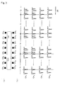
- Figs. 7(A) and (B) show one example of waveforms of the potentials obtained from the microelectrodes 2 of each channel and a plot of the peak time of each channel in a reentry model chip whereon cells are cultured as shown in Fig. 5(C) .
- Fig. 7(A) the potentials obtained from the microelectrodes 2 of each channel on both the right and left sides of the model reentry chip have waveforms with stable cycles in all channels.
- Fig. 7(B) is a plot of the peak time of each channel for analysis of the potential waveforms of Fig.
- Fig. 7(B) the peak times corresponding to the signals of the microelectrodes 2 on the left side of the reentry model chip are indicated as "x" and the peak times corresponding to the signals of the microelectrodes 2 on the right side of the reentry model chip are indicated as "o".
- the pulse waves propagate at about the same rate from channel 1 to channel 8, and the pulses originating from channel 1 spread to channel 8 in about 100 ms and then become extinct.
- the signals shown in Fig. 7(A) indicate normal cardiac activity.
- this is designated as "N" meaning it is normal.
- Fig. 8(A) shows a waveform diagram enabling easier evaluation wherein the signal shown in Fig. 7(A) indicates a state corresponding to normal cardiac activity.
- the waveform diagram of Fig. 8(A) is a sum of all of the signal waveforms from channel 1 to channel 8 shown in Fig. 7(A) . This processing can be carried out easily by the personal computer PC shown in Fig. 1 .
- the waveform diagram of Fig. 8(A) shows stable signals having a stable peak waveform with a specific cycle. This can easily be inferred from the correspondence between the waveform diagram of Fig. 8(A) and the waveform diagram of Fig. 7(A) , or the correspondence between the waveform diagram of Fig. 8(A) and the peak times of Fig. 7(B) .
- the waveform diagram of Fig. 8(A) therefore, has been designated as "N" to indicate a state of normal cardiac activity.
- Fig. 8(B) shows an example of an electrocardiogram in the normal range of a human electrocardiogram. From the stable peak waveform and stable cycle apparent from the comparison of the signal waveform shown in Fig. 8(A) with the waveform shown in Fig. 8(B) , it can be understood that the activity of the cells constituting the reentry model chip corresponds to normal activity analogous to normal cardiac activity.
- Fig. 8(C) shows the inferred propagation status of the pulsation of the cells constituting the reentry model chip corresponding to the state of normal cardiac activity.
- the cells near the microelectrodes of channel 1 on both the right and left sides serve as pacemakers (PM), and as shown by the arrows, the pulse wave propagates sequentially through the channels on both the right and left sides, and collides and goes extinct near the microelectrodes of channels 7 or 8. It is assumed that this repeats at a predetermined frequency.
- PM pacemakers
- Figs. 9(A) and (B) show a different example of electric potentials obtained from the microelectrodes 2 of each channel and a plot of the peak times of each channel of the reentry model chip whereon cells are cultured as shown in Fig. 5(C) .
- the potentials obtained from the microelectrodes 2 of each channel on both the right and left sides of the reentry model chip have waveforms with an unstable cycle in comparison with the waveforms of Fig. 7(A) .
- Fig. 9(A) the potentials obtained from the microelectrodes 2 of each channel on both the right and left sides of the reentry model chip have waveforms with an unstable cycle in comparison with the waveforms of Fig. 7(A) .
- FIG. 9(B) is a plot of the peak times of each channel for analysis of the potential waveforms of Fig. 9(A) , and is expressed by overlaying the time periods corresponding to the potential waveforms from both the right and left sides of the reentry model chip of Fig. 9(A) on the same time axis.
- This processing can be carried out easily with the personal computer PC shown in Fig. 1 . It is shown that the peak times at the tips of the arrows linking Fig. 9(A) with Fig. 9(B) are derived from the potential waveform signals at the bases of the arrows.
- the arrows with the solid lines relate to the signals of the microelectrodes 2 on the left side of the reentry model chip, and the arrows with the broken lines relate to the signals of the microelectrodes 2 on the right side of the reentry model chip.
- Fig. 9(B) the peak times corresponding to the signals of the microelectrodes 2 on the left side of the reentry model chip are indicated as an " ⁇ " and the peak times corresponding to the signals of the microelectrodes 2 on the right side of the reentry model chip are displayed as " ⁇ ".
- Figs. 9(A) and (B) are more complex than those of Figs. 7(A) and (B) .
- a pulse wave propagates from channel 1 to channel 8 at roughly the same speed; after propagation of a normal pulse (N 2 ) is measured wherein a pulse wave originating from channel 1 propagates to channel 8 at approximately 100 ms and then becomes extinct, the propagation of a pulse (E 2 ) is measured from the microelectrode 2 of channel 3 to channel 7 on the left side of the reentry model chip; after propagation of a pulse wave from the microelectrodes 2 of channel 1 to channel 8 on the right side of the reentry model chip, this is repeated; after propagation of a pulse (R 1 ) from the microelectrodes 2 of channel 8 to channel 1 on the left side of the reentry model chip, this is repeated; after propagation of a pulse wave from the microelectrodes 2 of channel 1 to channel 8 on the left side of the reentry model chip, this is repeated; after propagation of a pulse (R 2 ) from the microelectrodes 2 of channel 1 of channel 8 at
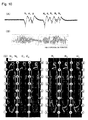
- Fig. 10(A) shows a waveform diagram enabling easier evaluation wherein the signal shown in Fig. 9(A) indicates a state corresponding to normal cardiac activity.
- the waveform diagram of Fig. 10(A) is a sum of all of the signal waveforms from channel 1 to channel 8 shown in Fig. 9(A) .
- This processing can be carried out easily with the personal computer PC shown in Fig. 1 .
- the waveform diagram of Fig. 10(A) corresponds well with the analysis of the peak times of Fig. 9(B) .
- the waveform of Fig. 10(A) indicates, therefore, that it is not a normal state of cardiac activity.
- Fig. 10(B) shows an example of a human electrocardiogram containing multiple arrhythmias and exceeding the normal range.
- the activity of the cells constituting the reentry model chip showing the signal waveform illustrated in Fig. 10(A) corresponds to abnormal activity similar to human cardiac activity in a case producing an electrocardiogram outside of normal cardiac activity.
- Fig. 10(C) is a diagram inferring the state of propagation of a pulse wave of the cells constituting the reentry model chip showing the waveforms and the peak times of Figs. 9(A) and (B) .
- N 1 and N 2 are similar to the example wherein the cells near the microelectrodes of channel 1 on both the right and left sides explained in Fig. 8(C) serve as pacemakers (PM), and as shown by the arrows, the pulse wave therefrom propagates sequentially along the channels on both sides, collides in the vicinity of the microelectrode of channel 7 or channel 8, and becomes extinct.
- E 1 and E 2 are examples wherein the cells near the microelectrode of channel 3 on the left side serve as pacemakers (PM), and as shown by the arrows, the pulse wave therefrom propagates sequentially only along the channels on the left side, and becomes extinct near the microelectrode of channel 7 or channel 8.
- PM pacemakers
- U is an example wherein cells near the microelectrode of channel 3 on the right side serve as pacemakers (PM), and as shown by the arrows, this pulse wave propagates sequentially only along the channels on the right side, propagates to channel 8 on the left side near the microelectrode of channel 7 or channel 8, and after propagating from channel 8 on the left side sequentially as far as channel 4, collides with the pulse generated by cells near the microelectrode of channel 3 on the left side and becomes extinct.
- PM pacemakers
- R 1 is an example wherein cells near the microelectrode of channel 1 on the right side serve as pacemakers (PM), and as shown by the arrows, this pulse wave propagates sequentially along the channels on the right side, propagates to channel 8 on the left side near the microelectrode of channel 7 or channel 8, and after reaching a state wherein it has propagated from channel 8 on the left side sequentially to channel 1, as additionally shown in R 2 , once again it becomes a pulse wave propagated via cells near the microelectrodes of the channels of the left side, and not only goes around, but as shown by R 3 , once again it becomes a pulse wave propagated via cells near the microelectrodes of the channels on the right side, and after propagating as far as channel 7, finally becomes extinct.
- PM pacemakers
- a cardiac reentry model chip in vitro featuring a mixture of cardiomyocytes and fibroblasts. Therefore, if a drug that is to act on the cells is supplied via pipe 8 3 , and the change in pulse potential shown in Fig. 3(b) is detected and evaluated, one can judge if the drug is useful or toxic in relation to cardiomyocytes. In other words, it is clear that if abnormal pulse potentials corresponding to arrhythmia become greater or the uninterrupted duration of their generation becomes longer, the drug is unsuitable, but if the abnormal pulse potentials corresponding to arrhythmia become smaller or the uninterrupted duration of their generation becomes shorter, the drug is suitable.
- the substrate 1 and electrode 2 are made of optically transparent materials, observations of the status of the cell pulsation made with an optical microscope can also be used. In such a case, the effect of a drug can be evaluated by multiple approaches rather than by evaluation by pulse potential alone. Conversely, if observations with an optical microscope are not made, there is no need to construct the substrate 1 and electrode 2 of an optically transparent material.
- the propagation of a pulse wave from adjacent cardiomyocytes or fibroblasts enables accurate measurement of cell potential and cell morphology on a single cell basis, and a chip can be provided whereupon a cardiac model constituting a closed loop comprising cardiomyocytes and fibroblasts suitably dispersed and arranged is constructed, and the effect of a drug can be evaluated thereby.
Landscapes
- Health & Medical Sciences (AREA)
- Life Sciences & Earth Sciences (AREA)
- Engineering & Computer Science (AREA)
- Biomedical Technology (AREA)
- Immunology (AREA)
- Chemical & Material Sciences (AREA)
- Molecular Biology (AREA)
- Urology & Nephrology (AREA)
- Hematology (AREA)
- Cell Biology (AREA)
- Physics & Mathematics (AREA)
- Analytical Chemistry (AREA)
- General Physics & Mathematics (AREA)
- Pathology (AREA)
- General Health & Medical Sciences (AREA)
- Food Science & Technology (AREA)
- Medicinal Chemistry (AREA)
- Biochemistry (AREA)
- Microbiology (AREA)
- Biotechnology (AREA)
- Bioinformatics & Cheminformatics (AREA)
- Toxicology (AREA)
- Tropical Medicine & Parasitology (AREA)
- Biophysics (AREA)
- Apparatus Associated With Microorganisms And Enzymes (AREA)
- Measuring Or Testing Involving Enzymes Or Micro-Organisms (AREA)
- Investigating Or Analysing Biological Materials (AREA)
Applications Claiming Priority (2)
| Application Number | Priority Date | Filing Date | Title |
|---|---|---|---|
| JP2007152692 | 2007-06-08 | ||
| PCT/JP2008/060447 WO2008149976A1 (ja) | 2007-06-08 | 2008-06-06 | 心臓リエントリーモデルチップおよび心臓リエントリーモデルチップによる薬剤の評価装置および方法 |
Publications (3)
| Publication Number | Publication Date |
|---|---|
| EP2157165A1 true EP2157165A1 (de) | 2010-02-24 |
| EP2157165A4 EP2157165A4 (de) | 2010-09-01 |
| EP2157165B1 EP2157165B1 (de) | 2012-12-26 |
Family
ID=40093780
Family Applications (1)
| Application Number | Title | Priority Date | Filing Date |
|---|---|---|---|
| EP08765260A Not-in-force EP2157165B1 (de) | 2007-06-08 | 2008-06-06 | Kardialer reentry-modelchip und vorrichtung und verfahren zur arzneimittelbeurteilung unter verwendung des kardialen reentry-modelchips |
Country Status (5)
| Country | Link |
|---|---|
| US (1) | US20100173351A1 (de) |
| EP (1) | EP2157165B1 (de) |
| JP (1) | JP5581499B2 (de) |
| CN (1) | CN101730736B (de) |
| WO (1) | WO2008149976A1 (de) |
Cited By (3)
| Publication number | Priority date | Publication date | Assignee | Title |
|---|---|---|---|---|
| EP2371941A4 (de) * | 2008-12-05 | 2012-09-12 | Nat Univ Corp Tokyo Med & Dent | Vorrichtung zur untersuchung von mykardialer toxizität, chip zur untersuchungvon myokardialer toxizität und verfahren zur untersuchung von myokardialer toxizität |
| US11193922B2 (en) | 2016-10-26 | 2021-12-07 | Roche Sequencing Solutions, Inc. | Multi-chip packaging of integrated circuits and flow cells for nanopore sequencing |
| US12618826B2 (en) | 2024-03-12 | 2026-05-05 | Roche Sequencing Solutions, Inc. | Multi-chip packaging of integrated circuits and flow cells for nanopore sequencing |
Families Citing this family (8)
| Publication number | Priority date | Publication date | Assignee | Title |
|---|---|---|---|---|
| JP6078943B2 (ja) | 2011-02-28 | 2017-02-15 | ソニー株式会社 | 画像処理装置および方法、並びに、プログラム |
| JPWO2013061849A1 (ja) * | 2011-10-28 | 2015-04-02 | 国立大学法人 東京医科歯科大学 | 心筋毒性検査および心筋細胞評価のための方法および装置 |
| CN104263804B (zh) * | 2014-09-15 | 2016-06-08 | 浙江大学 | 一种基于光学图像分析的心肌细胞机械搏动检测方法 |
| USD851276S1 (en) * | 2015-06-11 | 2019-06-11 | Yamaha Hatsudoki Kabushiki Kaisha | Placement and cluster sifting cell plate |
| JP6218199B1 (ja) * | 2016-10-06 | 2017-10-25 | 日本航空電子工業株式会社 | 電気化学測定装置及びトランスデューサ |
| CN108467835B (zh) * | 2018-03-16 | 2021-05-11 | 东南大学 | 用于心肌细胞三维功能性培养的微流控芯片及制备方法及力学电学特性检测方法 |
| CN108373974B (zh) * | 2018-03-19 | 2021-10-19 | 东南大学 | 用于三维培养细胞和原位实时监测心肌组织的芯片装置及其应用 |
| CN118159647A (zh) * | 2021-10-28 | 2024-06-07 | 富士胶片株式会社 | 心肌细胞层的制造方法、心肌细胞层及其利用 |
Family Cites Families (4)
| Publication number | Priority date | Publication date | Assignee | Title |
|---|---|---|---|---|
| JP2003513275A (ja) * | 1999-11-04 | 2003-04-08 | アドバンスド センサー テクノロジーズ, インコーポレイテッド | 統合された制御および解析回路を備えた微視的なマルチサイトセンサアレイ |
| JP4812271B2 (ja) * | 2004-08-30 | 2011-11-09 | 一般社団法人オンチップ・セロミクス・コンソーシアム | 心筋拍動細胞を用いた細胞バイオアッセイチップおよびこれを用いるバイオアッセイ |
| JP4664646B2 (ja) * | 2004-10-20 | 2011-04-06 | 一般社団法人オンチップ・セロミクス・コンソーシアム | 細胞培養用マイクロチャンバーおよび細胞構造構築法 |
| JP4535832B2 (ja) * | 2004-10-13 | 2010-09-01 | 有限責任中間法人 オンチップ・セロミクス・コンソーシアム | 異種細胞を用いる細胞再構成デバイスおよびこれを用いるバイオアッセイ |
-
2008
- 2008-06-06 US US12/663,441 patent/US20100173351A1/en not_active Abandoned
- 2008-06-06 WO PCT/JP2008/060447 patent/WO2008149976A1/ja not_active Ceased
- 2008-06-06 CN CN200880019300.7A patent/CN101730736B/zh not_active Expired - Fee Related
- 2008-06-06 EP EP08765260A patent/EP2157165B1/de not_active Not-in-force
- 2008-06-06 JP JP2009517909A patent/JP5581499B2/ja not_active Expired - Fee Related
Non-Patent Citations (9)
| Title |
|---|
| arturo picones: "Impact of High Throughput Electrophysiology in New Drug Discovery: Role of the IonWorksTM HT System in Drug Safety testing and Functional Assay Development." 4 June 2004 (2004-06-04), pages 1-35, XP002587483 Retrieved from the Internet: URL:http://www.moleculardevices.com/pdfs2/2004_presentations/picones_presentation.pdf [retrieved on 2010-06-15] * |
| HOFFMANN PETER ET AL: "Are hERG channel inhibition and QT interval prolongation all there is in drug-induced torsadogenesis? A review of emerging trends." JOURNAL OF PHARMACOLOGICAL AND TOXICOLOGICAL METHODS 2006 MAR-APR LNKD- PUBMED:16289936, vol. 53, no. 2, March 2006 (2006-03), pages 87-105, XP002586416 ISSN: 1056-8719 * |
| KANEKO ET AL: "Dependence of the community effect of cultured cardiomyocytes on the cell network pattern" BIOCHEMICAL AND BIOPHYSICAL RESEARCH COMMUNICATIONS, ACADEMIC PRESS INC. ORLANDO, FL, US LNKD- DOI:10.1016/J.BBRC.2007.03.005, vol. 356, no. 2, 4 April 2007 (2007-04-04) , pages 494-498, XP022090800 ISSN: 0006-291X * |
| KLAUKE NORBERT ET AL: "Extracellular recordings of field potentials from single cardiomyocytes." BIOPHYSICAL JOURNAL 1 OCT 2006 LNKD- PUBMED:16844752, vol. 91, no. 7, 1 October 2006 (2006-10-01), pages 2543-2551, XP002586414 ISSN: 0006-3495 * |
| KOJIMA K ET AL: "A novel method of cultivating cardiac myocites in agarose microchamber chips for studying cell synchronization" JOURNAL OF NANOBIOTECHNOLOGY, BIOMED CENTRAL, LONDON, GB LNKD- DOI:10.1186/1477-3155-2-9, vol. 2, no. 9, 1 January 2004 (2004-01-01) , pages 1-4, XP003012658 ISSN: 1477-3155 * |
| KOJIMA KENSUKE ET AL: "Role of the community effect of cardiomyocyte in the entrainment and reestablishment of stable beating rhythms." BIOCHEMICAL AND BIOPHYSICAL RESEARCH COMMUNICATIONS 8 DEC 2006 LNKD- PUBMED:17055457, vol. 351, no. 1, 8 December 2006 (2006-12-08), pages 209-215, XP002587484 ISSN: 0006-291X * |
| KOJIMA KENSUKE ET AL: "Two-dimensional network formation of cardiac myocytes in agar microculture chip with 1480 nm infrared laser photo-thermal etching." LAB ON A CHIP NOV 2003 LNKD- PUBMED:15007461, vol. 3, no. 4, November 2003 (2003-11), pages 292-296, XP002587485 ISSN: 1473-0197 * |
| See also references of WO2008149976A1 * |
| SUZUKI I ET AL: "Pattern modification of a neuronal network for individual-cell-based electrophysiological measurement using photothermal etching of an agarose architecture with a multielectrode array." IEE PROCEEDINGS. NANOBIOTECHNOLOGY JUN 2004 LNKD- PUBMED:16475853, vol. 151, no. 3, June 2004 (2004-06), pages 116-121, XP006022231 ISSN: 1478-1581 * |
Cited By (5)
| Publication number | Priority date | Publication date | Assignee | Title |
|---|---|---|---|---|
| EP2371941A4 (de) * | 2008-12-05 | 2012-09-12 | Nat Univ Corp Tokyo Med & Dent | Vorrichtung zur untersuchung von mykardialer toxizität, chip zur untersuchungvon myokardialer toxizität und verfahren zur untersuchung von myokardialer toxizität |
| US8877457B2 (en) | 2008-12-05 | 2014-11-04 | National University Corporation Tokyo Medical And Dental University | Device for examining myocardial toxicity, chip for examining myocardial toxicity and method for examining myocardial toxicity |
| US11193922B2 (en) | 2016-10-26 | 2021-12-07 | Roche Sequencing Solutions, Inc. | Multi-chip packaging of integrated circuits and flow cells for nanopore sequencing |
| US11953494B2 (en) | 2016-10-26 | 2024-04-09 | Roche Sequencing Solutions, Inc. | Multi-chip packaging of integrated circuits and flow cells for nanopore sequencing |
| US12618826B2 (en) | 2024-03-12 | 2026-05-05 | Roche Sequencing Solutions, Inc. | Multi-chip packaging of integrated circuits and flow cells for nanopore sequencing |
Also Published As
| Publication number | Publication date |
|---|---|
| EP2157165B1 (de) | 2012-12-26 |
| EP2157165A4 (de) | 2010-09-01 |
| JP5581499B2 (ja) | 2014-09-03 |
| US20100173351A1 (en) | 2010-07-08 |
| CN101730736B (zh) | 2014-01-15 |
| CN101730736A (zh) | 2010-06-09 |
| JPWO2008149976A1 (ja) | 2010-08-26 |
| WO2008149976A1 (ja) | 2008-12-11 |
Similar Documents
| Publication | Publication Date | Title |
|---|---|---|
| EP2157165A1 (de) | Kardialer reentry-modelchip und vorrichtung und verfahren zur arzneimittelbeurteilung unter verwendung des kardialen reentry-modelchips | |
| Israel et al. | An array of microelectrodes to stimulate and record from cardiac cells in culture | |
| Thomas Jr et al. | A miniature microelectrode array to monitor the bioelectric activity of cultured cells | |
| EP2157166A1 (de) | Modellzellenchip, vorrichtung zur beurteilung des arzneimitteleffektes unter verwendung des modellzellenchips und verfahren zur beurteilung des arzneimitteleffektes | |
| Kuperstein et al. | A practical 24 channel microelectrode for neural recording in vivo | |
| US6235520B1 (en) | High-throughput screening method and apparatus | |
| US20050231186A1 (en) | High throughput electrophysiology system | |
| US20140203818A1 (en) | System and method for monitoring cardiomyocyte beating, viability, morphology, and electrophysiological properties | |
| Nádasdy et al. | Extracellular recording and analysis of neuronal activity: from single cells to ensembles | |
| Starr et al. | An evaluation of photoengraved microelectrodes for extracellular single-unit recording | |
| Lopes et al. | Interfacing microfluidics with microelectrode arrays for studying neuronal communication and axonal signal propagation | |
| US20200158670A1 (en) | System and method for monitoring cardiomyocyte beating, viability, morphology and electrophysiological properties | |
| Egert et al. | Heart on a chip—extracellular multielectrode recordings from cardiac myocytes in vitro | |
| Israel et al. | Time delays in propagation of cardiac action potential | |
| WO2003031941A2 (en) | Detection and characterization of pyschoactives using parallel multi-site assays in neuronal tissue | |
| US20050237065A1 (en) | Compartment-arrayed probe for measuring extracellular electrical potential and method of measuring pharmacological effect using the same | |
| Orman et al. | Local axon collaterals of area CA1 support spread of epileptiform discharges within CA1, but propagation is unidirectional | |
| HK1144444A (en) | Cardiac reentry model chip and apparatus and method for evaluating drug using the cardiac reentry model chip | |
| Pickard et al. | Recording neural activity in the honeybee brain with micromachined silicon sensors | |
| Soussou et al. | Mapping spatio-temporal electrophysiological activity in hippocampal slices with conformal planar multi-electrode arrays | |
| Kawana et al. | Neurointerface-interfaces of neuronal networks to electrical circuit | |
| JPH08149998A (ja) | 細胞に対する薬剤等の効果を判定する装置及び方法 | |
| o cULTURED CELL | A MINATURE McRoELECTRooE ARRAY To MoNro. THE | |
| Van Wijk | Collagen gels populated with rat neonatal heart cells can be used for optical recording of rhythmic contractions which also show ECG-like potentials | |
| CN120998519A (zh) | 一种基于Belousov-Zhabotinsky反应的跨尺度心肌细胞信号传输方法 |
Legal Events
| Date | Code | Title | Description |
|---|---|---|---|
| PUAI | Public reference made under article 153(3) epc to a published international application that has entered the european phase |
Free format text: ORIGINAL CODE: 0009012 |
|
| 17P | Request for examination filed |
Effective date: 20091210 |
|
| AK | Designated contracting states |
Kind code of ref document: A1 Designated state(s): AT BE BG CH CY CZ DE DK EE ES FI FR GB GR HR HU IE IS IT LI LT LU LV MC MT NL NO PL PT RO SE SI SK TR |
|
| AX | Request for extension of the european patent |
Extension state: AL BA MK RS |
|
| RIN1 | Information on inventor provided before grant (corrected) |
Inventor name: TERAZONO, HIDEYUKI Inventor name: SUGIYAMA, ATSUSHI Inventor name: NOMURA, FUMIMASA Inventor name: FUKUSHIMA, MAMORU Inventor name: ANDO, KENTARO Inventor name: YASUDA, KENJI Inventor name: KANEKO, TOMOYUKI |
|
| A4 | Supplementary search report drawn up and despatched |
Effective date: 20100729 |
|
| DAX | Request for extension of the european patent (deleted) | ||
| 17Q | First examination report despatched |
Effective date: 20110704 |
|
| REG | Reference to a national code |
Ref country code: DE Ref legal event code: R079 Ref document number: 602008021161 Country of ref document: DE Free format text: PREVIOUS MAIN CLASS: C12M0003000000 Ipc: G01N0033500000 |
|
| RIC1 | Information provided on ipc code assigned before grant |
Ipc: G01N 33/50 20060101AFI20120117BHEP Ipc: G01N 33/487 20060101ALI20120117BHEP Ipc: G01N 33/543 20060101ALI20120117BHEP |
|
| GRAP | Despatch of communication of intention to grant a patent |
Free format text: ORIGINAL CODE: EPIDOSNIGR1 |
|
| GRAS | Grant fee paid |
Free format text: ORIGINAL CODE: EPIDOSNIGR3 |
|
| GRAA | (expected) grant |
Free format text: ORIGINAL CODE: 0009210 |
|
| AK | Designated contracting states |
Kind code of ref document: B1 Designated state(s): AT BE BG CH CY CZ DE DK EE ES FI FR GB GR HR HU IE IS IT LI LT LU LV MC MT NL NO PL PT RO SE SI SK TR |
|
| REG | Reference to a national code |
Ref country code: GB Ref legal event code: FG4D |
|
| REG | Reference to a national code |
Ref country code: CH Ref legal event code: EP |
|
| REG | Reference to a national code |
Ref country code: CH Ref legal event code: NV Representative=s name: BUGNION S.A., CH Ref country code: AT Ref legal event code: REF Ref document number: 590737 Country of ref document: AT Kind code of ref document: T Effective date: 20130115 |
|
| REG | Reference to a national code |
Ref country code: DE Ref legal event code: R096 Ref document number: 602008021161 Country of ref document: DE Effective date: 20130228 |
|
| PG25 | Lapsed in a contracting state [announced via postgrant information from national office to epo] |
Ref country code: LT Free format text: LAPSE BECAUSE OF FAILURE TO SUBMIT A TRANSLATION OF THE DESCRIPTION OR TO PAY THE FEE WITHIN THE PRESCRIBED TIME-LIMIT Effective date: 20121226 Ref country code: HR Free format text: LAPSE BECAUSE OF FAILURE TO SUBMIT A TRANSLATION OF THE DESCRIPTION OR TO PAY THE FEE WITHIN THE PRESCRIBED TIME-LIMIT Effective date: 20121226 Ref country code: FI Free format text: LAPSE BECAUSE OF FAILURE TO SUBMIT A TRANSLATION OF THE DESCRIPTION OR TO PAY THE FEE WITHIN THE PRESCRIBED TIME-LIMIT Effective date: 20121226 Ref country code: SE Free format text: LAPSE BECAUSE OF FAILURE TO SUBMIT A TRANSLATION OF THE DESCRIPTION OR TO PAY THE FEE WITHIN THE PRESCRIBED TIME-LIMIT Effective date: 20121226 Ref country code: NO Free format text: LAPSE BECAUSE OF FAILURE TO SUBMIT A TRANSLATION OF THE DESCRIPTION OR TO PAY THE FEE WITHIN THE PRESCRIBED TIME-LIMIT Effective date: 20130326 |
|
| REG | Reference to a national code |
Ref country code: AT Ref legal event code: MK05 Ref document number: 590737 Country of ref document: AT Kind code of ref document: T Effective date: 20121226 |
|
| REG | Reference to a national code |
Ref country code: LT Ref legal event code: MG4D |
|
| REG | Reference to a national code |
Ref country code: NL Ref legal event code: VDEP Effective date: 20121226 |
|
| PG25 | Lapsed in a contracting state [announced via postgrant information from national office to epo] |
Ref country code: GR Free format text: LAPSE BECAUSE OF FAILURE TO SUBMIT A TRANSLATION OF THE DESCRIPTION OR TO PAY THE FEE WITHIN THE PRESCRIBED TIME-LIMIT Effective date: 20130327 Ref country code: SI Free format text: LAPSE BECAUSE OF FAILURE TO SUBMIT A TRANSLATION OF THE DESCRIPTION OR TO PAY THE FEE WITHIN THE PRESCRIBED TIME-LIMIT Effective date: 20121226 Ref country code: LV Free format text: LAPSE BECAUSE OF FAILURE TO SUBMIT A TRANSLATION OF THE DESCRIPTION OR TO PAY THE FEE WITHIN THE PRESCRIBED TIME-LIMIT Effective date: 20121226 |
|
| PG25 | Lapsed in a contracting state [announced via postgrant information from national office to epo] |
Ref country code: IS Free format text: LAPSE BECAUSE OF FAILURE TO SUBMIT A TRANSLATION OF THE DESCRIPTION OR TO PAY THE FEE WITHIN THE PRESCRIBED TIME-LIMIT Effective date: 20130426 Ref country code: CZ Free format text: LAPSE BECAUSE OF FAILURE TO SUBMIT A TRANSLATION OF THE DESCRIPTION OR TO PAY THE FEE WITHIN THE PRESCRIBED TIME-LIMIT Effective date: 20121226 Ref country code: SK Free format text: LAPSE BECAUSE OF FAILURE TO SUBMIT A TRANSLATION OF THE DESCRIPTION OR TO PAY THE FEE WITHIN THE PRESCRIBED TIME-LIMIT Effective date: 20121226 Ref country code: ES Free format text: LAPSE BECAUSE OF FAILURE TO SUBMIT A TRANSLATION OF THE DESCRIPTION OR TO PAY THE FEE WITHIN THE PRESCRIBED TIME-LIMIT Effective date: 20130406 Ref country code: BE Free format text: LAPSE BECAUSE OF FAILURE TO SUBMIT A TRANSLATION OF THE DESCRIPTION OR TO PAY THE FEE WITHIN THE PRESCRIBED TIME-LIMIT Effective date: 20121226 Ref country code: BG Free format text: LAPSE BECAUSE OF FAILURE TO SUBMIT A TRANSLATION OF THE DESCRIPTION OR TO PAY THE FEE WITHIN THE PRESCRIBED TIME-LIMIT Effective date: 20130326 Ref country code: EE Free format text: LAPSE BECAUSE OF FAILURE TO SUBMIT A TRANSLATION OF THE DESCRIPTION OR TO PAY THE FEE WITHIN THE PRESCRIBED TIME-LIMIT Effective date: 20121226 Ref country code: AT Free format text: LAPSE BECAUSE OF FAILURE TO SUBMIT A TRANSLATION OF THE DESCRIPTION OR TO PAY THE FEE WITHIN THE PRESCRIBED TIME-LIMIT Effective date: 20121226 |
|
| PG25 | Lapsed in a contracting state [announced via postgrant information from national office to epo] |
Ref country code: PT Free format text: LAPSE BECAUSE OF FAILURE TO SUBMIT A TRANSLATION OF THE DESCRIPTION OR TO PAY THE FEE WITHIN THE PRESCRIBED TIME-LIMIT Effective date: 20130426 Ref country code: PL Free format text: LAPSE BECAUSE OF FAILURE TO SUBMIT A TRANSLATION OF THE DESCRIPTION OR TO PAY THE FEE WITHIN THE PRESCRIBED TIME-LIMIT Effective date: 20121226 Ref country code: RO Free format text: LAPSE BECAUSE OF FAILURE TO SUBMIT A TRANSLATION OF THE DESCRIPTION OR TO PAY THE FEE WITHIN THE PRESCRIBED TIME-LIMIT Effective date: 20121226 Ref country code: NL Free format text: LAPSE BECAUSE OF FAILURE TO SUBMIT A TRANSLATION OF THE DESCRIPTION OR TO PAY THE FEE WITHIN THE PRESCRIBED TIME-LIMIT Effective date: 20121226 |
|
| PG25 | Lapsed in a contracting state [announced via postgrant information from national office to epo] |
Ref country code: DK Free format text: LAPSE BECAUSE OF FAILURE TO SUBMIT A TRANSLATION OF THE DESCRIPTION OR TO PAY THE FEE WITHIN THE PRESCRIBED TIME-LIMIT Effective date: 20121226 |
|
| PLBE | No opposition filed within time limit |
Free format text: ORIGINAL CODE: 0009261 |
|
| STAA | Information on the status of an ep patent application or granted ep patent |
Free format text: STATUS: NO OPPOSITION FILED WITHIN TIME LIMIT |
|
| PG25 | Lapsed in a contracting state [announced via postgrant information from national office to epo] |
Ref country code: CY Free format text: LAPSE BECAUSE OF FAILURE TO SUBMIT A TRANSLATION OF THE DESCRIPTION OR TO PAY THE FEE WITHIN THE PRESCRIBED TIME-LIMIT Effective date: 20121226 |
|
| 26N | No opposition filed |
Effective date: 20130927 |
|
| PG25 | Lapsed in a contracting state [announced via postgrant information from national office to epo] |
Ref country code: IT Free format text: LAPSE BECAUSE OF FAILURE TO SUBMIT A TRANSLATION OF THE DESCRIPTION OR TO PAY THE FEE WITHIN THE PRESCRIBED TIME-LIMIT Effective date: 20121226 |
|
| REG | Reference to a national code |
Ref country code: DE Ref legal event code: R097 Ref document number: 602008021161 Country of ref document: DE Effective date: 20130927 |
|
| PG25 | Lapsed in a contracting state [announced via postgrant information from national office to epo] |
Ref country code: MC Free format text: LAPSE BECAUSE OF FAILURE TO SUBMIT A TRANSLATION OF THE DESCRIPTION OR TO PAY THE FEE WITHIN THE PRESCRIBED TIME-LIMIT Effective date: 20121226 |
|
| REG | Reference to a national code |
Ref country code: IE Ref legal event code: MM4A |
|
| REG | Reference to a national code |
Ref country code: DE Ref legal event code: R119 Ref document number: 602008021161 Country of ref document: DE Effective date: 20140101 |
|
| PG25 | Lapsed in a contracting state [announced via postgrant information from national office to epo] |
Ref country code: IE Free format text: LAPSE BECAUSE OF NON-PAYMENT OF DUE FEES Effective date: 20130606 Ref country code: DE Free format text: LAPSE BECAUSE OF NON-PAYMENT OF DUE FEES Effective date: 20140101 |
|
| PGFP | Annual fee paid to national office [announced via postgrant information from national office to epo] |
Ref country code: GB Payment date: 20140618 Year of fee payment: 7 |
|
| PGFP | Annual fee paid to national office [announced via postgrant information from national office to epo] |
Ref country code: CH Payment date: 20140618 Year of fee payment: 7 |
|
| PGFP | Annual fee paid to national office [announced via postgrant information from national office to epo] |
Ref country code: FR Payment date: 20140619 Year of fee payment: 7 |
|
| PG25 | Lapsed in a contracting state [announced via postgrant information from national office to epo] |
Ref country code: MT Free format text: LAPSE BECAUSE OF FAILURE TO SUBMIT A TRANSLATION OF THE DESCRIPTION OR TO PAY THE FEE WITHIN THE PRESCRIBED TIME-LIMIT Effective date: 20121226 |
|
| PG25 | Lapsed in a contracting state [announced via postgrant information from national office to epo] |
Ref country code: TR Free format text: LAPSE BECAUSE OF FAILURE TO SUBMIT A TRANSLATION OF THE DESCRIPTION OR TO PAY THE FEE WITHIN THE PRESCRIBED TIME-LIMIT Effective date: 20121226 |
|
| PG25 | Lapsed in a contracting state [announced via postgrant information from national office to epo] |
Ref country code: HU Free format text: LAPSE BECAUSE OF FAILURE TO SUBMIT A TRANSLATION OF THE DESCRIPTION OR TO PAY THE FEE WITHIN THE PRESCRIBED TIME-LIMIT; INVALID AB INITIO Effective date: 20080606 Ref country code: LU Free format text: LAPSE BECAUSE OF NON-PAYMENT OF DUE FEES Effective date: 20130606 |
|
| REG | Reference to a national code |
Ref country code: CH Ref legal event code: PL |
|
| GBPC | Gb: european patent ceased through non-payment of renewal fee |
Effective date: 20150606 |
|
| REG | Reference to a national code |
Ref country code: FR Ref legal event code: ST Effective date: 20160229 |
|
| PG25 | Lapsed in a contracting state [announced via postgrant information from national office to epo] |
Ref country code: GB Free format text: LAPSE BECAUSE OF NON-PAYMENT OF DUE FEES Effective date: 20150606 Ref country code: CH Free format text: LAPSE BECAUSE OF NON-PAYMENT OF DUE FEES Effective date: 20150630 Ref country code: LI Free format text: LAPSE BECAUSE OF NON-PAYMENT OF DUE FEES Effective date: 20150630 |
|
| PG25 | Lapsed in a contracting state [announced via postgrant information from national office to epo] |
Ref country code: FR Free format text: LAPSE BECAUSE OF NON-PAYMENT OF DUE FEES Effective date: 20150630 |