EP2157221A1 - Formgestrickte schlauchware, strickverfahren dafür sowie designvorrichtung - Google Patents
Formgestrickte schlauchware, strickverfahren dafür sowie designvorrichtung Download PDFInfo
- Publication number
- EP2157221A1 EP2157221A1 EP08751622A EP08751622A EP2157221A1 EP 2157221 A1 EP2157221 A1 EP 2157221A1 EP 08751622 A EP08751622 A EP 08751622A EP 08751622 A EP08751622 A EP 08751622A EP 2157221 A1 EP2157221 A1 EP 2157221A1
- Authority
- EP
- European Patent Office
- Prior art keywords
- knitting
- yarn
- needle
- needle bed
- fabric
- Prior art date
- Legal status (The legal status is an assumption and is not a legal conclusion. Google has not performed a legal analysis and makes no representation as to the accuracy of the status listed.)
- Granted
Links
Images




Classifications
-
- D—TEXTILES; PAPER
- D04—BRAIDING; LACE-MAKING; KNITTING; TRIMMINGS; NON-WOVEN FABRICS
- D04B—KNITTING
- D04B1/00—Weft knitting processes for the production of fabrics or articles not dependent on the use of particular machines; Fabrics or articles defined by such processes
- D04B1/22—Weft knitting processes for the production of fabrics or articles not dependent on the use of particular machines; Fabrics or articles defined by such processes specially adapted for knitting goods of particular configuration
-
- D—TEXTILES; PAPER
- D04—BRAIDING; LACE-MAKING; KNITTING; TRIMMINGS; NON-WOVEN FABRICS
- D04B—KNITTING
- D04B7/00—Flat-bed knitting machines with independently-movable needles
- D04B7/24—Flat-bed knitting machines with independently-movable needles for producing patterned fabrics
- D04B7/26—Flat-bed knitting machines with independently-movable needles for producing patterned fabrics with colour patterns
-
- D—TEXTILES; PAPER
- D10—INDEXING SCHEME ASSOCIATED WITH SUBLASSES OF SECTION D, RELATING TO TEXTILES
- D10B—INDEXING SCHEME ASSOCIATED WITH SUBLASSES OF SECTION D, RELATING TO TEXTILES
- D10B2403/00—Details of fabric structure established in the fabric forming process
- D10B2403/01—Surface features
- D10B2403/011—Dissimilar front and back faces
- D10B2403/0114—Dissimilar front and back faces with one or more yarns appearing predominantly on one face, e.g. plated or paralleled yarns
Definitions
- the present invention relates to a plating-knitted tubular fabric using a front yarn and a back yarn as knitting yarns to form a tubular shaped fabric by a flatbed knitting machine, the knitting method therefore, and a design apparatus.
- a flatbed knitting machine having at least a pair of front and rear needle beds disposed in such a manner that head end portions are opposed each other with a needle bed gap in-between, is able to form a tubular shaped fabric by plating-knitting (for example, see Patent Citation 1).
- plating-knitting when a yarn should be caught to a hook of a knitting needle that carries out knitting motion, a front yarn and a back yarn are fed with a height difference provided.
- Using different colors for the front yarn and the back yarn can make the color of a fabric different between the outside and the inside to be knitted as a tubular shaped fabric.
- Such a fabric is able to be used as a reversible fabric that can be worn with one surface side and the other surface side turned over.
- a plating-knitted fabric knitted in two colors for one surface side and the other surface side is worn with the one surface side only, the color effect different from a fabric knitted by a single knitting yarn can be obtained.
- Patent Citation 1 a structure of a apparatus that feeds a front yarn and a back yarn from one yarn carrier, which having two yarn feeder ports above and below, is disclosed.
- the two above and below yarn feeder ports have their locations displaced so that the yarn feeder port for the front yarn leads and the yarn feeder port for the back yarn follows with respect to the yarn carrier moving direction. Since, in order to knit a fabric into a tubular shape, the yarn carrier shuttles back and forth by reversing the knitting direction in the needle bed on the other side with respect to the horizontal knitting direction in the needle bed on one side, locations of two yarn feeder ports are changed over in accordance with the knitting direction.
- a front yarn In case that a tubular shaped fabric is plating-knitted, a front yarn must be fed in such a manner that the front yarn constantly leads the back yarn. Since in a flatbed knitting machine, the knitting direction is reversed at the end portion of the knitting width, at the end portion of at least either one of the knitting width, locations of the yarn feeder ports of the front yarn and the back yarn are changed over, and a crossed portion is formed between the front yarn and the back yarn. The crossed portion causes the next stitch to be formed with the positional relationship between the front yarn and the back yarn instantaneously reversed.
- Patent Citation 2 discloses a knitting method that makes the blurring less noticeable at the knitting width end portion on the side where the yarn cross occurs in a plating-knitted wide-rib structure using a flatbed knitting machine.
- the wide-rib structure is one of rib structures to be formed with front stitches and back stitches, and formed by alternately repeating a section with a plurality of front stitches and a section with a plurality of back stitches.
- one fabric uses the front stitch of the rib structure as the edge stitch and the other fabric uses the back stitch as the edge stitch.
- the knitting direction is reversed and the back stitches of the rib structure of the other fabric are knitted, so that a cross of knitting yarns is formed at the loop of the wide-rib structure, and the color blurring of knitting yarns can be made less noticeable.
- the tubular fabric includes a C-letter shaped fabric in which the front and the back fabrics end in mid-course of the knitting width, like a cardigan, in addition to a complete tubular shaped fabric in which the front and the back fabrics continue without break in midcourse of the knitting width.”
- the C-letter shaped fabric is included in the tubular shaped fabric.
- the present invention provides a plating-knitted tubular fabric knitted in a tubular shape by shuttling a front yarn and a back yarn to feed for plating-knit, in the horizontal direction of needle beds opposed to each other in front and rear, wherein:
- the plating-knitted tubular fabric is characterized in that the crossed portion of the front yarn and the back yarn is located within a range from the needle loop through the twisted loop to a sinker loop of a stitch on one end side knitted on the opposed needle bed.
- the present invention provides a method for knitting a plating-knitted tubular fabric, using a flatbed knitting machine equipped with at least a pair of front and rear needle beds placed opposite to each other with a needle bed gap in-between, and feeding a front yarn and a back yarn as knitting yarns from different yarn feeder ports respectively, in such a manner that the front yarn leads and the back yarn follows to carry out plating-knitting, wherein:
- the method for knitting the plating-knitted tubular fabric is characterized in that:
- the present invention provides a design apparatus for generating knitting control data for knitting a fabric in tubular shape while feeding a front yarn and a back yarn as knitting yarns from different yarn feeder ports respectively, to a flatbed knitting machine equipped with at least a pair of needle beds opposite to each other with a needle bed gap in-between so that the front yarn leads and the back yarn follows to carry out plating-knitting, wherein:
- the fabric knitted by at least one of the front and rear needle beds has a twisted loop with a knitting yarn from a needle loop crossed and then connected to sinker loops on both sides on one end of each knitting course.
- a crossed portion between a front yarn and a back yarn is located, and therefore, even when the back yarn comes out to the surface side at the crossed portion and color blurring may occur, the color blurring is able to be made less apparent, and the color blurring caused by crossing of knitting yarns can be solved, whereby commodity value of the fabric can be increased.
- the crossed portion between the front yarn and the back yarn is located within a range from the needle loop through the twisted loop to a sinker loop of a stitch on one end side knitted on the opposite needle bed, and therefore, the color blurring can be made less apparent from both of the front side and the back side of the fabric.
- shuttle knitting is done by reversing knitting direction at knitting ends.
- occurrence of crossing between a front yarn and a back under yarn at one end of the knitting width cannot be avoided because of the reversal of the positional relation between the front yarn and the back yarn which are fed by shifting the position.
- the final stitch in the knitting course on one side of the knitting direction becomes a twisted loop.
- the cross of the front yarn with the back yarn is generated in a section between the twisted loop and the stitches knitted on the opposite needle bed. Since the knitting yarn in this section is less likely to appear to the fabric surface, even if the cross of the front yarn and the back yarn occurs when a tubular shaped fabric is plating-knitted on the front and rear needle bed of a flatbed knitting machine, it is possible to make a phenomenon less likely to occur, that the back yarn comes out to the surface side resulting in color blurring. Since the color blurring caused by the cross between knitting yarns can be solved, the commodity value of the tubular shaped fabric to be knitted can be increased.
- the needle bed to which the knitting needle which should form the final stitch in the knitting course on one side is horizontally displaced by racking with respect to the needle bed opposite to the needle bed, whereby the space between the twisted loop and the stitches linked to the twisted loop on the opposite needle bed is expanded.
- the cross of the front yarn with the back yarn might occur in a relatively short section, or might occur under an unstable state in parallel over a relatively long section.
- the knitting control data for plating-knitting a tubular shaped fabric by a flatbed knitting machine is generated in such a manner that the final stitch in the knitting course on one side of the knitting direction becomes a twisted loop and a cross of a front yarn with a back yarn is allowed to occur within a range between the twisted loop and stitches knitted by the opposite needle bed.
- the knitting yarn of this range is less likely to come out to the surface side of the fabric, even if the cross of the front yarn with the back yarn occurs when the tubular shaped fabric is plating-knitted on the front and the rear needle beds of a flatbed knitting machine, it is possible to make the phenomenon of color blurring in which the back yarn comes out to the surface side is less likely to occur. Since the color blurring caused by the cross between knitting yarns is solved, the commodity value of the tubular shaped fabric to be knitted can be increased.
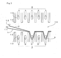
- Fig. 1 schematically shows a knitting procedure for plating-knitting a tubular shaped fabric by a flatbed knitting machine equipped with needle beds in front and rear as one embodiment of the present invention.
- the front and rear needle beds of the flatbed knitting machine have the front needle bed designated as F and the rear needle bed designated as B.
- F front needle bed
- B rear needle bed
- Both needle beds are disposed opposite to each other with the needle bed gap in-between.
- the knitting needles of each needle bed have hooks at the head end advanced and retreated to and from the needle bed gap.
- Above the needle bed gap there are disposed a plurality of yarn feeders.
- Above the needle bed gap there are disposed a plurality of yarn feeder rails, too. Yarn feeders are supported by any of the yarn feeder rails to be able to move rightward and leftward.
- uppercase characters "A” through “T” denote the knitting needles including the range used for knitting in the front needle bed F
- lowercase characters "a” through “t” denote the knitting needles including the range used for knitting in the rear needle bed B, respectively.
- an open circle indicates that the stitch is retained.
- a solid circle indicates that a new stitch is formed.
- S-letter on the left side indicates the standard condition.
- Arrow marks on the right side indicate knitting direction.
- every other knitting needles on the F side "A”, “C”, “E”, ..., “S” are basically allotted to the front-side fabric. Every other knitting needles on the B side, “b”, “d”, “f”, ..., “t” are used to carry out half gauge knitting basically allotted to the back-side fabric. Idle needles "B”, “D”, “F', ..., “T” on the F side are located opposite to knitting needles "b", “d”, “f”, ..., “t” on the B side, and are used for transferring stitches from the B side or for knitting back stitches, or the like.
- Reference numerals 1 and 2 shown on the left side of Fig. 1 denote steps of the knitting procedure which carries out treatment to reduce effect of color blurring caused by the cross of the front yarn with the back yarn at the knitting end on the left side of the needle bed.
- a case is assumed in which yarn feeders used for feeding front yarns are supported by the yarn feeder rails, respectively, in such a manner that the yarn feeders horizontally advance and retire in front of the yarn feeders used for feeing back yarns.
- the knitting direction is reversed from the knitting on the front needle bed to the knitting on the rear needle bed, the cross of the front yarn with the back yarn occurs.
- Step 1 and Step 2 can make less apparent the color blurring caused by the cross of the front yarn and the back yarn.
- Step 1 on one side of the knitting direction for knitting the portion up to the end portion of the knitting width in which the cross occurs between the front yarn and the back yarn, for example, in the leftward knitting course, stitches are formed on knitting needles "S", “Q”, “O”, ..., "C” of the F side except for the final stitch at the knitting needle "A”, and no knitting needle is allowed to be caught on a knitting needle "A” which should form the final stitch.
- Yarn feeders that feed the front yarn and the back yarn are moved in such a manner that the knitting yarns pass the position of the knitting needle "A" and come out to the outside of the knitting width.
- Step 2 in the knitting course on the other side in which the knitting direction is reversed rightward, the knitting needle "A” is driven to knit together with knitting needles "b", “d”, “f”, ..., “t” which should knit stitches on the B side opposite to the F side in which the knitting needle “A” forms the final stitch to form stitches on each of the knitting needles "A", “b”, “d”, “f”, ..., “t”.
- the stitch formed on the knitting needle “A” on the F side becomes a twisted loop which is different from stitches formed on other knitting needles "S", “Q”, “O”, ...,”C” on the F side.
- the cross of the front yarn with the back yarn occurs at the portion in which knitting yarns are crossed-over continuously from the twisted loop of the knitting needle "A” on the F side to stitches of the knitting needle "b” on one end side on the B side, and does not occur at the stitch "b". Therefore, a phenomenon in which the back yarn emerges to the surface side and causes the color blurring can be made less noticeable.
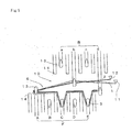
- Fig. 2 shows a range in which the cross occurs between the front yarn and the back yarn by knitting of Step 2 in Fig. 1 .
- the front yarn 1 and the back yarn 2 are fed to knit a tubular shaped fabric by plating-knitting, on the knitting needles "E” and “C” on the F side, front-side stitches 3 are formed, and on the knitting needles "b” and “d” on the B side, back-side stitches 4 are formed, respectively, and at the same time, on the final knitting needle "A” on the F side, a twisted loop 5 is formed.
- the crossed portion 6 between the front yarn 1 and the back yarn 2 is able to be generated in the range shown in black color as a portion which is transferred from the twisted loop 5 to the back-side stitch 4 of the knitting needle "b" on the B side.
- Figs. 3 , 4 , 5 , and 6 schematically show a process in which the cross of the front yarn 1 with the back yarn 2 occurs at the crossed portion 6 of Fig. 2 .
- Advance or retreat of the knitting needle 13 to and from the needle bed gap 10 is driven by, for example, a cam carried on a carriage which advances and retires horizontally along the needle bed, but the illustration of the carriage is omitted.
- movement of the yarn feeders 11 and 12 is carried out in conjunction with the carriage, too.
- Fig. 3 shows a condition right after leftward knitting in Step 1 of Fig. 1 is completed, that is, the condition right before rightward knitting in Step 2 of Fig. 1 begins.
- the front and rear needle beds F and B are opposed to each other with the needle bed gap 10 in-between.
- the front yarn 1 and the back yarn 2 are fed from yarn feeders 11 and 12, respectively, which move in the needle bed gap 10 horizontally.
- the yarn feeder 11 that feeds the front yarn 1 is located on the front side than the yarn feeder 12 that feeds the back yarn 2.
- the knitting needles "C” and “E” on the F side advances to the needle bed gap 10, retracts the front yarn 1 and the back yarn 2 by a hook, and forms a stitch loop by a needle loop formed by a knitting needle 13 and a sinker loop formed by a sinker 14. Since the knitting needle "A” on the F side does not advance to the needle bed gap and the front yarn 1 and the back yarn 2 pass the location of the knitting needle “A” from the hook of the knitting needle “C” that forms the final stitch, passes through the outside of the leftward knitting width, and extends to the yarn feeders 11 and 12 in standby.
- Fig. 4 shows a condition right after the rightward knitting is started in Step 2 of Fig. 1 . Since the yarn feeder 11 feeding the front yarn 1 precedes the yarn feeder 12 feeding the back yarn 2, even if the yarn feeder 11 is located on the left side than the yarn feeder 12 in Fig. 3 , it precedes to the right side in Fig. 4 . The last knitting needle "A" on the F side advanced to the needle bed gap 10 before yarn feeders 11 and 12 traverse rightward, and pass above the front yarn 1 and the back yarn 2 extending leftward shown in Fig. 3 .
- Fig. 5 shows a condition in which the yarn feeders 11 and 12 move rightward from the position in Fig. 4 , the knitting needle "A" on the F side retracts the front yarn 1 and the back yarn 2 to a certain extent, and the knitting needle “b” on the B side begins retracting, too. Because in this way, the front yarn 1 and the back yarn 2 are retracted in order of the knitting needle "A” on the F side and the knitting needle “b” on the B side, the crossed portion 6 is formed between the front yarn 1 and the back yarn 2, and when the knitting yarn is retracted at the knitting needle "b" on the B side, the front yarn 1 and the back yarn 2 can be retracted with the front side and the back side of the front yarn 1 and the back yarn 2 brought to be normal.
- the crossed portion 6 of the front yarn 1 with the back yarn 2 might occur in a relatively short section or in an unstable state in which the front yarn 1 and the back yarn 2 go side by side over a relatively long section in accordance with the positional relationship between yarn feeders 11 and 12. Expanding the range between the knitting needle "A” on the F side and the knitting needle “b” on the B side by racking can form the crossed portion 6 definitely between the knitting needle "A” and the knitting needle "b".
- Fig. 6 shows a condition when rightward knitting shown in Step 2 of Fig. 1 is finished.
- Each knitting needle 13 is retracted into each needle bed so as that the head end of knitting needle 13 gets further away from the needle bed gap 10 than the sinker 14. It is preferable to retract the knitting needle "A" on the F side under the conditions in which the crossed portion 6 of the front yarn 1 with the back yarn 2 is formed on the hook side of the knitting needle "A" than the sinker 14 adjacent to the knitting needle "A".
- Fig. 7 shows the stitch structure of a tubular shaped fabric formed with the knitting of Fig. 3 through Fig. 6 included.
- the twisted loop 5 formed by the knitting needle "A" on the F side is twisted so as that the portion linked from a needle loop 5a to a sinker loop 5b between adjacent front-side stitch 3 and the back-side stitch 4 crosses.
- the crossed portion 6 of the front yarn 1 and the back yarn 2 is able to be generated on the hook side of the knitting needle 13 from the sinker 14, in the knitting structure, the crossed portion 6 is able to be generated at the twisted loop 5 and at the location between the sinker loop 5b and the needle loop 5a on the front and rear boundary 10c side. If the cross is able to be generated at above location, even if the back yarn 2 emerges to the surface side due to the cross, it is possible to make it less apparent.
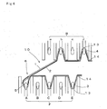
- Fig. 8 shows a knitting procedure when a tubular shaped fabric is knitted in a C-letter shape as the other embodiment according to the present invention. That is, the tubular shaped fabric is knitted by one of the front and rear needle beds using, for example, whole knitting needles "b", “d”, “f”, ..., “t” of the knitting width in the case of the rear needle bed B, and knitting needles "A", “C”, “E”, “G”, and “I”; “K”, “M”, “O”, “Q”, and “S” on both end portions excluding the intermediate portion of the knitting width in the case of the front needle bed F, which is the other one of the front and rear needle beds.
- Step 1 on one end side of the front needle bed, for example, in the case of knitting needles "K”, “M”, “O”, “Q”, and “S” on the right end side, the knitting yarn is fed leftward, i.e., the inward of the knitting width, and then, as shown in Step 2, the feeding direction is reversed and the knitting yarn is fed rightward, i.e., outward of the knitting width.
- Step 3 after the feeding direction is reversed, on the B side, the knitting yarn is fed leftward in order of knitting needles "t", “r", “p”, ..., "d” from the right end side of the knitting width to the left-end side, excluding the final knitting needle "b".
- Step 4 after the feeding direction is reversed, the knitting yarn is fed rightward, i.e., inward of the knitting width to the knitting needle "b" of the B side and knitting needles "A", “C”, “E”, “G”, and “I” on the left end side of the F side from the left end side.
- Step 5 the feeding direction is reversed and the knitting yarn is fed leftward, i.e., outward of the knitting width to knitting needles "I", "G”, “E”, and “C” on the left end side on the F side excluding the final knitting needle "A".
- the knitting yarn is fed rightward to the knitting needle "A” on the F side and knitting needles "b", “c”, “f”, ..., "t” from the left end side to the right end side on the B side.
- the present embodiment forms a tubular shaped fabric by repeating feeding the knitting yarn back and forth in the C-letter shape as a whole.
- Feeding yarn by the use of a yarn carrier which is equipped with two yarn feeder ports as disclosed in Patent Citation 1 and is able to change over the yarn feeding position of the two yarn feeder ports can carry out the treatment of forming a twisted loop and preventing the color blurring collectively on the left side.
- a yarn carrier which is equipped with two yarn feeder ports as disclosed in Patent Citation 1 and is able to change over the yarn feeding position of the two yarn feeder ports
- the yarn feeder 11 feeding the front yarn 1 is located on the front side of the yarn feeder 12 feeding the back yarn 2
- knitting is carried out to form a twisted loop also on the knitting needle "S", on the right end on the F side, not in Step 3 and Step 4 of Fig. 8 but in Step 2 and Step 3 of Fig. 8 .
- Step 4 of Fig. 8 no racking is performed and instead, in Step 3, racking is carried out to shift the needle bed B by four pitches with respect to the needle bed F.
- the C-letter shaped tubular fabric shown in Fig. 8 is formed by connecting, on both side ends of the knitting width, a fabric which is continuous on one needle bed to a fabric which is not continuous at the intermediate on the other needle bed.
- the C-letter shaped tubular fabric is able to be knitted by connecting the continuous fabrics on both needle beds at one end only of the knitting width and not connecting on the other end of the knitting width. Even in this kind of tubular shaped fabric, the color blurring problem is same as Fig. 8 , and the preventive treatment can be conducted in the same manner.
- Fig. 9 and Fig. 10 show examples of plating-knitted tubular fabric knitted by the use of SWG-FIRST (product name), no-sewing computerized flatbed knitting machine commercially available from Shima Seiki Mfg., Ltd. having a knitting needle arrangement pitch of 12G.
- SWG-FIRST product name
- no-sewing computerized flatbed knitting machine commercially available from Shima Seiki Mfg., Ltd. having a knitting needle arrangement pitch of 12G.
- Fig. 9 shows an example of a tubular shaped fabric 20 formed by both C-letter shape knitting as shown in Fig. 8 and round knitting as shown in Fig. 1 .
- a front-side fabric 21a is knitted on the front needle bed and a back-side fabric 21b is knitted on the rear needle bed.
- the front-side fabric 21a and the back-side fabric 21b are connected at the boundary portion 21c which corresponds to the needle bed gap.
- the front-side fabric 21a lacking the intermediate portion is knitted so as to be folded back at an end portion 21d.
- the front-side fabric 22a and the back-side fabric 22b are connected at the boundary portion 22c, which corresponds to the needle bed gap.
- the boundary portions 21c and 22c the color blurring due to the cross of the front yarn with the back yarn scarcely occurs.
- both C-knitted portion 21 and the round-knitted portion 22 are included, but even in the case of including one portion only, the color blurring becomes less apparent, thereby increasing the commodity value.
- Fig. 10 shows an example of a tubular shaped fabric 30 knitted for comparison with Fig. 9 .
- the tubular shaped fabric 30 is knitted without carrying out color blurring preventive treatment by forming a twisted loop and racking.
- a front-side fabric 31a is knitted on the front needle bed and a back-side fabric 31b is knitted on the rear needle bed.
- the front-side fabric 31a and the back-side fabric 31b are connected at a boundary portion 31c that corresponds to the needle bed gap.
- the front-side fabric 31c lacking the intermediate portion is knitted so as to be folded back at an end portion 31d.
- a round-knitted portion 32 in which round-knitting is conducted, the front-side fabric 32a and the back-side fabric 32b are connected at the boundary portion 32c which corresponds to the needle bed gap.
- the color blurring due to the cross of the front yarn with the back yarn occurs.
- feeding front and back yarns by the use of a yarn carrier which has two yarn feeder ports and is able to change over the yarn feeding position of two yarn feeder ports as in the case of the C-knitted portion 21 of Fig. 9 enables the color blurring to occur in stitches on both ends which sandwich the one boundary portion 31c of the knitting width and not to occur on the other boundary portion of the knitting width.
- the color blurring occurs on one side of the knitting width and it is impossible to make the color blurring less apparent as in the case of the boundary portion 21c shown in Fig. 9 .
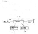
- Fig. 11 schematically shows a structure of a design apparatus 20 which generates the knitting control data to make the color blurring due to the cross of the front yarn with the back yarn less apparent in the plating-knitting of the tubular shaped fabric as shown in Fig. 1 and Fig. 8 by a flatbed knitting machine.
- the design apparatus 40 is achieved by installing software that executes knit-fabric design to a general-purpose computer 41.
- an input unit 42 such as a keyboard, digitizer, mouse, or the like
- a display unit 43 such as graphic display, or the like
- a communication device 44 capable of communications with the outside via LAN, or the like
- an external recorder 45 to which various detachable recording media are mounted, and other units are connected.
- Software can be installed to the computer 41 by downloading via the communication device 44 or by mounting recording media to the external recorder 45.
- An operator enters design data to the input unit 42, and designs the tubular shaped fabric 20 shown in Fig. 9 , or the like while monitoring the design results displayed on the display unit 43.
- the operator designates the C-knitted portion 21, round-knitted portion 22, or the like.
- the operator designates a yarn feeder or yarn carrier that feeds the front yarn and the back yarn. Based on the arrangement of the yarn feeder port decided pursuant to this designation, the computer 41 can decide the knitting needle which forms a twisted loop and can generate the knitting control data including the procedure to make the color blurring less apparent.
- the knitting control data containing above mentioned procedures is prepared as a standard and is able to be inserted into the computer in accordance with the selection of the operator.
- the knitting control data generated is transmitted to a flatbed knitting machine via the communication device 44 or recorded in recording media such as disks and USB memory, and entered into the flatbed knitting machine to knit the tubular shaped fabric 20 or the like.
Landscapes
- Engineering & Computer Science (AREA)
- Textile Engineering (AREA)
- Knitting Of Fabric (AREA)
- Knitting Machines (AREA)
Applications Claiming Priority (2)
| Application Number | Priority Date | Filing Date | Title |
|---|---|---|---|
| JP2007121800 | 2007-05-02 | ||
| PCT/JP2008/001097 WO2008139710A1 (ja) | 2007-05-02 | 2008-04-25 | プレーティング編成筒状編地およびその編成方法、ならびにデザイン装置 |
Publications (3)
| Publication Number | Publication Date |
|---|---|
| EP2157221A1 true EP2157221A1 (de) | 2010-02-24 |
| EP2157221A4 EP2157221A4 (de) | 2014-11-05 |
| EP2157221B1 EP2157221B1 (de) | 2015-11-18 |
Family
ID=40001936
Family Applications (1)
| Application Number | Title | Priority Date | Filing Date |
|---|---|---|---|
| EP08751622.5A Active EP2157221B1 (de) | 2007-05-02 | 2008-04-25 | Formgestrickte schlauchware, strickverfahren dafür sowie designvorrichtung |
Country Status (4)
| Country | Link |
|---|---|
| EP (1) | EP2157221B1 (de) |
| JP (1) | JP5307001B2 (de) |
| CN (1) | CN101668886B (de) |
| WO (1) | WO2008139710A1 (de) |
Cited By (2)
| Publication number | Priority date | Publication date | Assignee | Title |
|---|---|---|---|---|
| EP2354284A1 (de) * | 2010-02-03 | 2011-08-10 | Shima Seiki Mfg. Ltd. | Strickverfahren in Plattiertechnik |
| US20250230586A1 (en) * | 2024-01-17 | 2025-07-17 | Board Of Supervisors Of Louisiana State University And Agricultural And Mechanical College | Cloth comprising thermochromic yarns |
Families Citing this family (11)
| Publication number | Priority date | Publication date | Assignee | Title |
|---|---|---|---|---|
| CN102421949B (zh) * | 2009-05-08 | 2013-09-11 | 株式会社岛精机制作所 | 筒状针织物的编织方法及筒状针织物 |
| JP5695846B2 (ja) * | 2010-03-16 | 2015-04-08 | 株式会社島精機製作所 | Vネック尖端部の編成方法、およびvネックを有するニットウエア |
| WO2013108506A1 (ja) | 2012-01-20 | 2013-07-25 | 株式会社島精機製作所 | フットウェア、および編地の編成方法 |
| CN105074069B (zh) | 2013-02-25 | 2017-03-22 | 株式会社岛精机制作所 | 鞋帮的编织方法 |
| KR101698078B1 (ko) * | 2015-04-13 | 2017-01-19 | 파이룽 머시너리 밀 코., 엘티디. | 평판 편물기용 테크니컬 면의 일면에 교대 플레이팅을 편물하는 방법 |
| JP6526554B2 (ja) | 2015-12-25 | 2019-06-05 | 株式会社島精機製作所 | 編地の編成方法 |
| JP6518608B2 (ja) * | 2016-03-01 | 2019-05-22 | 株式会社島精機製作所 | 筒状編地の編成方法 |
| JP6415680B1 (ja) * | 2017-12-28 | 2018-10-31 | ニッティド株式会社 | 肉厚部を備えた横編地の編成方法、及び肉厚部を備えた横編地 |
| CN108532105B (zh) * | 2018-04-16 | 2019-08-16 | 惠州学院 | 一种在针织物上编织动态图案的方法 |
| JP7425006B2 (ja) * | 2020-02-17 | 2024-01-30 | 株式会社島精機製作所 | 編地の編成方法 |
| JP7434035B2 (ja) * | 2020-04-01 | 2024-02-20 | 株式会社島精機製作所 | 筒状編地の編成方法 |
Family Cites Families (4)
| Publication number | Priority date | Publication date | Assignee | Title |
|---|---|---|---|---|
| WO2001064989A1 (fr) * | 2000-02-29 | 2001-09-07 | Shima Seiki Mfg.,Ltd. | Jeteur pour metier a tricoter trame |
| TW483962B (en) * | 2000-02-29 | 2002-04-21 | Shima Seiki Mfg | Method of knitting plating of tubular knitting fabric by four-sheet bed weft knifting machine |
| TW561210B (en) * | 2000-02-29 | 2003-11-11 | Shima Seiki Mfg | Yarn carrier of weft knitting machine |
| JP4180527B2 (ja) * | 2004-01-30 | 2008-11-12 | 株式会社島精機製作所 | プレーティングによるワイドリブ組織の編成方法 |
-
2008
- 2008-04-25 WO PCT/JP2008/001097 patent/WO2008139710A1/ja not_active Ceased
- 2008-04-25 CN CN200880014043.8A patent/CN101668886B/zh active Active
- 2008-04-25 EP EP08751622.5A patent/EP2157221B1/de active Active
- 2008-04-25 JP JP2009514003A patent/JP5307001B2/ja active Active
Cited By (2)
| Publication number | Priority date | Publication date | Assignee | Title |
|---|---|---|---|---|
| EP2354284A1 (de) * | 2010-02-03 | 2011-08-10 | Shima Seiki Mfg. Ltd. | Strickverfahren in Plattiertechnik |
| US20250230586A1 (en) * | 2024-01-17 | 2025-07-17 | Board Of Supervisors Of Louisiana State University And Agricultural And Mechanical College | Cloth comprising thermochromic yarns |
Also Published As
| Publication number | Publication date |
|---|---|
| CN101668886B (zh) | 2011-12-07 |
| EP2157221A4 (de) | 2014-11-05 |
| JPWO2008139710A1 (ja) | 2010-07-29 |
| EP2157221B1 (de) | 2015-11-18 |
| JP5307001B2 (ja) | 2013-10-02 |
| CN101668886A (zh) | 2010-03-10 |
| WO2008139710A1 (ja) | 2008-11-20 |
Similar Documents
| Publication | Publication Date | Title |
|---|---|---|
| EP2157221B1 (de) | Formgestrickte schlauchware, strickverfahren dafür sowie designvorrichtung | |
| EP1972706B1 (de) | Flachstrickmaschine mit ketteneintrag und damit durchgeführtes strickverfahren | |
| EP2565308B1 (de) | Verbindungsverfahren für benachbarte maschenwarenteile und maschenware | |
| JP2021021163A (ja) | 編糸の位置が変更可能な緯編機編成構造 | |
| KR100540376B1 (ko) | 인타샤 패턴 편성포의 편성방법 및 그 편성 프로그램생성장치 | |
| EP1652980B1 (de) | Strickverfahren für schlauchförmige strickware mit streifenmuster sowie schlauchförmige strickware mit streifenmuster | |
| EP2568066B1 (de) | Strickanfangsverfahren für Maschenware | |
| KR101059853B1 (ko) | 플레이팅에 의한 와이드 리브 조직의 편성방법 | |
| CN101395312B (zh) | 形成放针线圈的方法及在针织物的编织宽度方向端部的内侧形成放针线圈的针织物 | |
| KR100833520B1 (ko) | 인타샤 패턴 편성포의 편성방법 | |
| JP5702576B2 (ja) | 編地の編成方法、および編地 | |
| EP2154280B1 (de) | Gewebe mit garnveredelungsabschnitt, behandlungsverfahren dafür sowie designvorrichtung | |
| EP2546399B1 (de) | Verfahren für Startstrickreihen einer Maschenware sowie Maschenware | |
| JP3406085B2 (ja) | 筒状編地の編み幅側縁部に縄柄を編成する方法 | |
| EP2455521B1 (de) | Einrichtungsverfahren für Maschenware | |
| US6079232A (en) | Widening method | |
| EP3165652B1 (de) | Strickverfahren und rundstrickmaschine | |
| EP2354284A1 (de) | Strickverfahren in Plattiertechnik | |
| KR102232288B1 (ko) | 가변 얀 위치를 갖는 위편기 편직 구조 | |
| KR102940918B1 (ko) | 통모양 편성포의 편성방법 | |
| JP4030542B2 (ja) | 編レースの製造方法 | |
| JP2000303327A (ja) | 増目の編成方法 | |
| CN113493954B (zh) | 筒状编织物的编织方法 | |
| JPS63145459A (ja) | 両面パイル経編地の編成方法 | |
| JPH07324260A (ja) | 進入防止片を備えた横編機 |
Legal Events
| Date | Code | Title | Description |
|---|---|---|---|
| PUAI | Public reference made under article 153(3) epc to a published international application that has entered the european phase |
Free format text: ORIGINAL CODE: 0009012 |
|
| 17P | Request for examination filed |
Effective date: 20091202 |
|
| AK | Designated contracting states |
Kind code of ref document: A1 Designated state(s): AT BE BG CH CY CZ DE DK EE ES FI FR GB GR HR HU IE IS IT LI LT LU LV MC MT NL NO PL PT RO SE SI SK TR |
|
| AX | Request for extension of the european patent |
Extension state: AL BA MK RS |
|
| DAX | Request for extension of the european patent (deleted) | ||
| A4 | Supplementary search report drawn up and despatched |
Effective date: 20141007 |
|
| RIC1 | Information provided on ipc code assigned before grant |
Ipc: D04B 15/00 20060101ALI20140930BHEP Ipc: D04B 7/26 20060101ALI20140930BHEP Ipc: D04B 7/02 20060101ALI20140930BHEP Ipc: D04B 1/22 20060101AFI20140930BHEP |
|
| GRAP | Despatch of communication of intention to grant a patent |
Free format text: ORIGINAL CODE: EPIDOSNIGR1 |
|
| INTG | Intention to grant announced |
Effective date: 20150608 |
|
| GRAS | Grant fee paid |
Free format text: ORIGINAL CODE: EPIDOSNIGR3 |
|
| GRAA | (expected) grant |
Free format text: ORIGINAL CODE: 0009210 |
|
| AK | Designated contracting states |
Kind code of ref document: B1 Designated state(s): AT BE BG CH CY CZ DE DK EE ES FI FR GB GR HR HU IE IS IT LI LT LU LV MC MT NL NO PL PT RO SE SI SK TR |
|
| REG | Reference to a national code |
Ref country code: GB Ref legal event code: FG4D |
|
| REG | Reference to a national code |
Ref country code: CH Ref legal event code: EP |
|
| REG | Reference to a national code |
Ref country code: AT Ref legal event code: REF Ref document number: 761637 Country of ref document: AT Kind code of ref document: T Effective date: 20151215 |
|
| REG | Reference to a national code |
Ref country code: IE Ref legal event code: FG4D |
|
| REG | Reference to a national code |
Ref country code: DE Ref legal event code: R096 Ref document number: 602008041262 Country of ref document: DE |
|
| REG | Reference to a national code |
Ref country code: NL Ref legal event code: MP Effective date: 20160218 |
|
| REG | Reference to a national code |
Ref country code: LT Ref legal event code: MG4D |
|
| REG | Reference to a national code |
Ref country code: AT Ref legal event code: MK05 Ref document number: 761637 Country of ref document: AT Kind code of ref document: T Effective date: 20151118 |
|
| PG25 | Lapsed in a contracting state [announced via postgrant information from national office to epo] |
Ref country code: HR Free format text: LAPSE BECAUSE OF FAILURE TO SUBMIT A TRANSLATION OF THE DESCRIPTION OR TO PAY THE FEE WITHIN THE PRESCRIBED TIME-LIMIT Effective date: 20151118 Ref country code: NO Free format text: LAPSE BECAUSE OF FAILURE TO SUBMIT A TRANSLATION OF THE DESCRIPTION OR TO PAY THE FEE WITHIN THE PRESCRIBED TIME-LIMIT Effective date: 20160218 Ref country code: ES Free format text: LAPSE BECAUSE OF FAILURE TO SUBMIT A TRANSLATION OF THE DESCRIPTION OR TO PAY THE FEE WITHIN THE PRESCRIBED TIME-LIMIT Effective date: 20151118 Ref country code: IS Free format text: LAPSE BECAUSE OF FAILURE TO SUBMIT A TRANSLATION OF THE DESCRIPTION OR TO PAY THE FEE WITHIN THE PRESCRIBED TIME-LIMIT Effective date: 20160318 Ref country code: LT Free format text: LAPSE BECAUSE OF FAILURE TO SUBMIT A TRANSLATION OF THE DESCRIPTION OR TO PAY THE FEE WITHIN THE PRESCRIBED TIME-LIMIT Effective date: 20151118 Ref country code: NL Free format text: LAPSE BECAUSE OF FAILURE TO SUBMIT A TRANSLATION OF THE DESCRIPTION OR TO PAY THE FEE WITHIN THE PRESCRIBED TIME-LIMIT Effective date: 20151118 |
|
| PG25 | Lapsed in a contracting state [announced via postgrant information from national office to epo] |
Ref country code: PT Free format text: LAPSE BECAUSE OF FAILURE TO SUBMIT A TRANSLATION OF THE DESCRIPTION OR TO PAY THE FEE WITHIN THE PRESCRIBED TIME-LIMIT Effective date: 20160318 Ref country code: AT Free format text: LAPSE BECAUSE OF FAILURE TO SUBMIT A TRANSLATION OF THE DESCRIPTION OR TO PAY THE FEE WITHIN THE PRESCRIBED TIME-LIMIT Effective date: 20151118 Ref country code: GR Free format text: LAPSE BECAUSE OF FAILURE TO SUBMIT A TRANSLATION OF THE DESCRIPTION OR TO PAY THE FEE WITHIN THE PRESCRIBED TIME-LIMIT Effective date: 20160219 Ref country code: PL Free format text: LAPSE BECAUSE OF FAILURE TO SUBMIT A TRANSLATION OF THE DESCRIPTION OR TO PAY THE FEE WITHIN THE PRESCRIBED TIME-LIMIT Effective date: 20151118 Ref country code: SE Free format text: LAPSE BECAUSE OF FAILURE TO SUBMIT A TRANSLATION OF THE DESCRIPTION OR TO PAY THE FEE WITHIN THE PRESCRIBED TIME-LIMIT Effective date: 20151118 Ref country code: LV Free format text: LAPSE BECAUSE OF FAILURE TO SUBMIT A TRANSLATION OF THE DESCRIPTION OR TO PAY THE FEE WITHIN THE PRESCRIBED TIME-LIMIT Effective date: 20151118 Ref country code: FI Free format text: LAPSE BECAUSE OF FAILURE TO SUBMIT A TRANSLATION OF THE DESCRIPTION OR TO PAY THE FEE WITHIN THE PRESCRIBED TIME-LIMIT Effective date: 20151118 |
|
| PG25 | Lapsed in a contracting state [announced via postgrant information from national office to epo] |
Ref country code: CZ Free format text: LAPSE BECAUSE OF FAILURE TO SUBMIT A TRANSLATION OF THE DESCRIPTION OR TO PAY THE FEE WITHIN THE PRESCRIBED TIME-LIMIT Effective date: 20151118 |
|
| REG | Reference to a national code |
Ref country code: DE Ref legal event code: R097 Ref document number: 602008041262 Country of ref document: DE |
|
| PG25 | Lapsed in a contracting state [announced via postgrant information from national office to epo] |
Ref country code: SK Free format text: LAPSE BECAUSE OF FAILURE TO SUBMIT A TRANSLATION OF THE DESCRIPTION OR TO PAY THE FEE WITHIN THE PRESCRIBED TIME-LIMIT Effective date: 20151118 Ref country code: EE Free format text: LAPSE BECAUSE OF FAILURE TO SUBMIT A TRANSLATION OF THE DESCRIPTION OR TO PAY THE FEE WITHIN THE PRESCRIBED TIME-LIMIT Effective date: 20151118 Ref country code: DK Free format text: LAPSE BECAUSE OF FAILURE TO SUBMIT A TRANSLATION OF THE DESCRIPTION OR TO PAY THE FEE WITHIN THE PRESCRIBED TIME-LIMIT Effective date: 20151118 Ref country code: RO Free format text: LAPSE BECAUSE OF FAILURE TO SUBMIT A TRANSLATION OF THE DESCRIPTION OR TO PAY THE FEE WITHIN THE PRESCRIBED TIME-LIMIT Effective date: 20151118 Ref country code: BE Free format text: LAPSE BECAUSE OF NON-PAYMENT OF DUE FEES Effective date: 20160430 |
|
| PLBE | No opposition filed within time limit |
Free format text: ORIGINAL CODE: 0009261 |
|
| STAA | Information on the status of an ep patent application or granted ep patent |
Free format text: STATUS: NO OPPOSITION FILED WITHIN TIME LIMIT |
|
| 26N | No opposition filed |
Effective date: 20160819 |
|
| PG25 | Lapsed in a contracting state [announced via postgrant information from national office to epo] |
Ref country code: SI Free format text: LAPSE BECAUSE OF FAILURE TO SUBMIT A TRANSLATION OF THE DESCRIPTION OR TO PAY THE FEE WITHIN THE PRESCRIBED TIME-LIMIT Effective date: 20151118 |
|
| REG | Reference to a national code |
Ref country code: CH Ref legal event code: PL |
|
| GBPC | Gb: european patent ceased through non-payment of renewal fee |
Effective date: 20160425 |
|
| PG25 | Lapsed in a contracting state [announced via postgrant information from national office to epo] |
Ref country code: LU Free format text: LAPSE BECAUSE OF FAILURE TO SUBMIT A TRANSLATION OF THE DESCRIPTION OR TO PAY THE FEE WITHIN THE PRESCRIBED TIME-LIMIT Effective date: 20160425 Ref country code: BE Free format text: LAPSE BECAUSE OF FAILURE TO SUBMIT A TRANSLATION OF THE DESCRIPTION OR TO PAY THE FEE WITHIN THE PRESCRIBED TIME-LIMIT Effective date: 20151118 |
|
| REG | Reference to a national code |
Ref country code: IE Ref legal event code: MM4A |
|
| REG | Reference to a national code |
Ref country code: FR Ref legal event code: ST Effective date: 20161230 |
|
| PG25 | Lapsed in a contracting state [announced via postgrant information from national office to epo] |
Ref country code: FR Free format text: LAPSE BECAUSE OF NON-PAYMENT OF DUE FEES Effective date: 20160502 Ref country code: CH Free format text: LAPSE BECAUSE OF NON-PAYMENT OF DUE FEES Effective date: 20160430 Ref country code: GB Free format text: LAPSE BECAUSE OF NON-PAYMENT OF DUE FEES Effective date: 20160425 Ref country code: LI Free format text: LAPSE BECAUSE OF NON-PAYMENT OF DUE FEES Effective date: 20160430 |
|
| PG25 | Lapsed in a contracting state [announced via postgrant information from national office to epo] |
Ref country code: IE Free format text: LAPSE BECAUSE OF NON-PAYMENT OF DUE FEES Effective date: 20160425 |
|
| PG25 | Lapsed in a contracting state [announced via postgrant information from national office to epo] |
Ref country code: HU Free format text: LAPSE BECAUSE OF FAILURE TO SUBMIT A TRANSLATION OF THE DESCRIPTION OR TO PAY THE FEE WITHIN THE PRESCRIBED TIME-LIMIT; INVALID AB INITIO Effective date: 20080425 Ref country code: CY Free format text: LAPSE BECAUSE OF FAILURE TO SUBMIT A TRANSLATION OF THE DESCRIPTION OR TO PAY THE FEE WITHIN THE PRESCRIBED TIME-LIMIT Effective date: 20151118 |
|
| PG25 | Lapsed in a contracting state [announced via postgrant information from national office to epo] |
Ref country code: TR Free format text: LAPSE BECAUSE OF FAILURE TO SUBMIT A TRANSLATION OF THE DESCRIPTION OR TO PAY THE FEE WITHIN THE PRESCRIBED TIME-LIMIT Effective date: 20151118 Ref country code: MT Free format text: LAPSE BECAUSE OF NON-PAYMENT OF DUE FEES Effective date: 20160430 Ref country code: MC Free format text: LAPSE BECAUSE OF FAILURE TO SUBMIT A TRANSLATION OF THE DESCRIPTION OR TO PAY THE FEE WITHIN THE PRESCRIBED TIME-LIMIT Effective date: 20151118 |
|
| PG25 | Lapsed in a contracting state [announced via postgrant information from national office to epo] |
Ref country code: BG Free format text: LAPSE BECAUSE OF FAILURE TO SUBMIT A TRANSLATION OF THE DESCRIPTION OR TO PAY THE FEE WITHIN THE PRESCRIBED TIME-LIMIT Effective date: 20151118 |
|
| PGFP | Annual fee paid to national office [announced via postgrant information from national office to epo] |
Ref country code: IT Payment date: 20260326 Year of fee payment: 19 |
|
| PGFP | Annual fee paid to national office [announced via postgrant information from national office to epo] |
Ref country code: DE Payment date: 20260324 Year of fee payment: 19 |