EP2157238A1 - Dispositif de production de bandes de matière fibreuse de papier, de carton ou autres revêtues dotées au moins d'une couche thermosensible et procédé de fonctionnement d'un tel dispositif - Google Patents
Dispositif de production de bandes de matière fibreuse de papier, de carton ou autres revêtues dotées au moins d'une couche thermosensible et procédé de fonctionnement d'un tel dispositif Download PDFInfo
- Publication number
- EP2157238A1 EP2157238A1 EP09168032A EP09168032A EP2157238A1 EP 2157238 A1 EP2157238 A1 EP 2157238A1 EP 09168032 A EP09168032 A EP 09168032A EP 09168032 A EP09168032 A EP 09168032A EP 2157238 A1 EP2157238 A1 EP 2157238A1
- Authority
- EP
- European Patent Office
- Prior art keywords
- web
- functional layer
- layer
- forming unit
- coating
- Prior art date
- Legal status (The legal status is an assumption and is not a legal conclusion. Google has not performed a legal analysis and makes no representation as to the accuracy of the status listed.)
- Granted
Links
- 238000000034 method Methods 0.000 title claims abstract description 12
- 239000000123 paper Substances 0.000 title abstract description 28
- 239000002657 fibrous material Substances 0.000 title abstract 2
- 238000001035 drying Methods 0.000 claims abstract description 125
- 238000000576 coating method Methods 0.000 claims abstract description 50
- 239000011248 coating agent Substances 0.000 claims abstract description 48
- 239000010410 layer Substances 0.000 claims description 93
- 239000002346 layers by function Substances 0.000 claims description 73
- 239000007788 liquid Substances 0.000 claims description 2
- 235000011837 pasties Nutrition 0.000 claims description 2
- 238000011144 upstream manufacturing Methods 0.000 claims description 2
- 239000007787 solid Substances 0.000 claims 1
- 238000004519 manufacturing process Methods 0.000 abstract description 4
- 238000007766 curtain coating Methods 0.000 abstract 6
- 230000015572 biosynthetic process Effects 0.000 abstract 2
- 238000010438 heat treatment Methods 0.000 abstract 2
- 230000008859 change Effects 0.000 description 15
- 238000011161 development Methods 0.000 description 15
- 230000018109 developmental process Effects 0.000 description 15
- 239000000463 material Substances 0.000 description 8
- 238000004804 winding Methods 0.000 description 8
- 230000006870 function Effects 0.000 description 7
- 239000011241 protective layer Substances 0.000 description 7
- 230000004913 activation Effects 0.000 description 3
- 238000010586 diagram Methods 0.000 description 3
- 230000008569 process Effects 0.000 description 3
- 239000011230 binding agent Substances 0.000 description 2
- 238000006243 chemical reaction Methods 0.000 description 2
- 230000008878 coupling Effects 0.000 description 2
- 238000010168 coupling process Methods 0.000 description 2
- 238000005859 coupling reaction Methods 0.000 description 2
- 238000007670 refining Methods 0.000 description 2
- 239000004753 textile Substances 0.000 description 2
- XLYOFNOQVPJJNP-UHFFFAOYSA-N water Chemical compound O XLYOFNOQVPJJNP-UHFFFAOYSA-N 0.000 description 2
- 230000009471 action Effects 0.000 description 1
- 230000003213 activating effect Effects 0.000 description 1
- 230000006978 adaptation Effects 0.000 description 1
- 230000008901 benefit Effects 0.000 description 1
- 238000005352 clarification Methods 0.000 description 1
- 239000011247 coating layer Substances 0.000 description 1
- 230000009849 deactivation Effects 0.000 description 1
- 238000002845 discoloration Methods 0.000 description 1
- 230000000694 effects Effects 0.000 description 1
- 238000007602 hot air drying Methods 0.000 description 1
- 238000003384 imaging method Methods 0.000 description 1
- 239000000155 melt Substances 0.000 description 1
- 239000000203 mixture Substances 0.000 description 1
- 230000037361 pathway Effects 0.000 description 1
- 239000002985 plastic film Substances 0.000 description 1
- 229920006255 plastic film Polymers 0.000 description 1
- 230000009993 protective function Effects 0.000 description 1
Images





Classifications
-
- D—TEXTILES; PAPER
- D21—PAPER-MAKING; PRODUCTION OF CELLULOSE
- D21H—PULP COMPOSITIONS; PREPARATION THEREOF NOT COVERED BY SUBCLASSES D21C OR D21D; IMPREGNATING OR COATING OF PAPER; TREATMENT OF FINISHED PAPER NOT COVERED BY CLASS B31 OR SUBCLASS D21G; PAPER NOT OTHERWISE PROVIDED FOR
- D21H23/00—Processes or apparatus for adding material to the pulp or to the paper
- D21H23/02—Processes or apparatus for adding material to the pulp or to the paper characterised by the manner in which substances are added
- D21H23/22—Addition to the formed paper
- D21H23/46—Pouring or allowing the fluid to flow in a continuous stream on to the surface, the entire stream being carried away by the paper
- D21H23/48—Curtain coaters
-
- B—PERFORMING OPERATIONS; TRANSPORTING
- B05—SPRAYING OR ATOMISING IN GENERAL; APPLYING FLUENT MATERIALS TO SURFACES, IN GENERAL
- B05C—APPARATUS FOR APPLYING FLUENT MATERIALS TO SURFACES, IN GENERAL
- B05C5/00—Apparatus in which liquid or other fluent material is projected, poured or allowed to flow on to the surface of the work
- B05C5/005—Curtain coaters
Definitions
- the invention relates to a device for producing coated paper, cardboard or other fibrous webs with at least one thermosensitive layer as a functional layer by applying a thermosensitive coating medium on a carrier web by means of a functional layer forming unit comprising an applicator and a drying line.
- the invention further relates to a method for operating a device for producing coated paper, cardboard or other fibrous webs with at least one thermosensitive layer.
- carrier webs are to be understood which have at least one thermosensitive layer on one or both sides.
- suitable webs such as films, in particular plastic films or textile webs are inventively treatable.
- thermosensitive layer is understood to mean a coating layer which is suitable for imaging visually detectable information by discoloration on exposure to heat, in particular contact with a heatable writing head. This comprises at least a color former, a color developer and a binder.
- the invention is therefore based on the object, a device for providing coated paper, - cardboard or other fibrous webs, in particular in the form of thermal paper to develop such that the disadvantages are avoided.
- the device should be characterized by a structurally simple design with a low number of components and be suitable, a carrier web both one-sided multiple, especially many times to coat or on both sides to provide at least one, preferably two coatings.
- a conversion to the different types of coated paper, cardboard or other fibrous webs should be possible with little control engineering effort and free of retooling promptly on request.
- a device for producing coated paper, board or other fibrous webs with at least one thermosensitive layer as a functional layer by applying a thermosensitive coating medium on a carrier web by means of a functional layer forming unit comprising an applicator and a drying line is characterized in that the first Functional unit forming unit comprises an applicator in the form of a multi-layer curtain applicator with at least one dispensing nozzle and a downstream drying section and the second functional layer forming unit also comprises an applicator in the form of a multi-layer curtain applicator with at least one dispensing nozzle and a downstream drying section, wherein a first Bru Adjustsweg below Including the applicator of the second functional layer-forming unit and a second web guide path and means for bypassing the applicator v are looked.
- the device according to the invention is characterized by the provision of only two functional layers forming units, which are suitable by the intelligent arrangement and control of their operations, a variety of different types of one or both sides single or multiple coated paper, cardboard or other fibrous webs to produce with little effort , free from a conversion of the device. This exists the possibility of a timely change with optimal utilization of the individual components of the individual functional layers forming units.
- the means for bypassing the applicator device to include the easiest case guide and / or guide elements for guiding the carrier web, which are arranged and designed to be suitable, a branch in the web guide behind the first functional layer-forming unit and before the application device of Forming second functional layer forming unit to form the first Bruestsweges on the applicator and the second Bruestsweges in the form of a bypass to the applicator and a merger of the two web guide paths.
- a multiplicity of possible, differently coated paper, board or other fibrous webs already result in this basic design.
- At least one material web coated on one side can be produced by activating the curtain application unit of the first functional layer-forming unit and the subsequent drying section. If, in addition, a further layer is applied directly to the first layer, the carrier web is guided over the drying section of the second functional layer-forming unit so that a single-side double-coated material web can be produced by utilizing the drying capacity of the second functional layer-forming unit.
- the carrier web can be guided either with deactivated application device of the second functional layer-forming unit via the first web guide path within this or via the second Bru Adjustsweg directly to the drying section of the second functional layer-forming unit.
- the application device of the second functional layer-forming unit is activated and the carrier web guided over the first Bru arrangementsweg within this, depending on the arrangement and web guide between the first and second functional layer-forming device either a coating on the Back of the carrier web or another third layer can be applied to the same side.
- the drying capacity of the drying section of the first functional layer-forming unit is to be designed for twice the order, so that the required dry content of the coating is achieved before the application of the further third layer.
- the application device and the drying section in a functional layer-forming unit are designed and arranged such that the carrier web within at least the first, preferably also the second functional layer-forming unit is guided free from a change of direction (reversal of the direction taken curve) in the longitudinal direction of the device considered it is ensured that in any case the coated surface is subjected to secondary drying.
- the arrangement and alignment of the components of the functional layer-forming units to each other there are basically two options. According to a first embodiment, these are preferably in a common horizontal plane, i. arranged offset from each other in the vertical direction. According to a second embodiment, the arrangement with offset in the vertical direction to each other.
- the first embodiment forms a very compact in terms of extent in the height direction unit, while the second embodiment allows adaptation to space conditions.
- the arrangement of the individual functional layers forming units can be done in various ways.
- the arrangement of the functional layer-forming units in the direction of passage of the carrier web takes place behind one another such that the guide direction of the carrier web in the connecting region between the two functional layer-forming units is characterized by at least one change of direction in the longitudinal direction of the device.
- the intended direction change in particular a loop-like leadership allows an arrangement of the functional layer-forming devices in vertically offset planes, wherein the offset in the longitudinal direction of the device between the two functional layer-forming units can be minimized.
- the first embodiment is characterized by a high degree of compactness in the longitudinal direction with simultaneous optimal utilization of space in the vertical direction.
- the arrangement of the unit forming the second functional layer spatially in the longitudinal direction of the device takes place completely in the region of the extension of the first functional layer-forming unit.
- the two functional layer-forming units are formed and arranged one behind the other viewed in the longitudinal direction of the device, that the guidance of the carrier web in the longitudinal direction of the device is free from a reversal of the taken curve direction.
- the two functional layer-forming units are arranged in a horizontal plane.
- the first and the second functional layer-forming unit are aligned in opposite directions.
- the carrier web is guided between the two functional layer-forming units without further interposition of a web turning devices such that they undergo a reversal of the orientation of their top and bottom between these, in particular with respect to the respective applicators of the individual functional layer forming unit.
- the orientation change of the carrier web sides with respect to the respective application devices of the individual functional layer-forming units is in the simplest case via means for changing the direction of the web guide with respect to the longitudinal direction of the device, in particular the corresponding arrangement of web guiding and guide rollers.
- the drying section of the second functional layer-forming unit can either be arranged downstream of the means for bypassing the application device of the second functional layer-forming unit, in particular by-pass or, according to a second embodiment, in the bypass.
- the means for web guide in these areas are designed and arranged such that these according to the first embodiment, a guide of the carrier web through the second functional layer forming unit regardless of whether the carrier web on the applicator and subsequently the drying line or bypassing the applicator via the drying section is guided, always allow in the same direction.
- the drying section in the different modes which are characterized by the different ways of guiding the carrier web on the applicator or bypassing this, in the opposite direction.
- the first embodiment can be configured in a particularly space-saving manner by the two functional layers forming units are arranged offset from one another in the vertical direction, wherein the position of applicator and drying line between them in the longitudinal direction of the device is reversed.
- the second embodiment allows the arrangement of application device and drying section of the second functional layer-forming unit in vertically offset planes free of offset in the longitudinal direction of each other.
- the application device of the functional layer-forming units comprises a multi-layer curtain applicator, which allows an application of application medium in the form of a single or multi-layer application media curtain produced at a trailing edge and moving in the direction of the carrier web in free fall.
- the curtain applicator comprises at least one applicator nozzle extending in the width direction of the carrier web, which has at least one application media feed with an application media supply system connected is.
- the nozzle or the curtain applicator can be formed in a known manner as a slot die or slide die. This allows the simultaneous application of at least two layers with one device.
- At least two application media provision systems can be assigned to the rapid change between different types of layer to be applied by means of a curtain applicator, which can be accessed alternately depending on the requirements of the application medium, for example by the optional coupling of the application media supply with the different application media delivery systems.
- the individual drying section of a functional layer-forming unit comprises at least one drying device, in particular in the form of a contactless drying, such as a hot-air drying device.
- a contactless drying such as a hot-air drying device.
- This can be gas or steam heated.
- Other drying systems such as infrared radiators and contact dryers, such as drying cylinders, are also possible.
- the drying section is designed as a function of the dry content of the layer applied with the upstream application device.
- the drying section is preferably straight, but may also be characterized by a curved or other course. The drying can be done on one side or on both sides, whereby designs with either one- or two-sided operation are conceivable.
- the carrier web is usually unrolled from a web roll and pulled through the device by means of appropriate pulling devices. Subsequent to the second functional layer-forming unit, the winding of the coated fibrous web takes place on a take-up device.
- each functional layer-forming unit is associated with a pulling device.
- thermosensitive layers can be applied as functional layers in addition to thermosensitive layers and other layers, such as cover layers in the form of protective layers.
- the latter are characterized by a lower basis weight in the range of 0.5 to 6 g / m 2 than the thermosensitive layers, the basis weight of which is preferably selected in the range of 1 to 7 g / m 2 .
- a web turning device is provided to form a further third web guide path and means for bypassing the web turning device between two functional layers forming units.
- the second application device of the second functional layer-forming unit also comprises a multi-layer curtain application unit. This makes it possible to produce a plurality of desired different layers even with the second functional layer-forming unit.
- the solution according to the invention is particularly suitable for the production of thermal paper.
- the invention can also be applied to other web-form materials suitable as recording media, such as films or textile materials
- the device according to the invention can be operated by controlling the web guide and the individual components of the functional layer-forming units in different operating modes.
- a first mode of operation the carrier web is guided successively forming at least one first layer through the first functional layer-forming unit and a second layer through the second functional layer-forming unit, while in a further second mode of operation the carrier web successively forming at least a first layer through the first Functional layer-forming unit and free of an order by the second functional layer-forming unit is performed.
- a first mode of operation the carrier web is guided successively forming at least one first layer through the first functional layer-forming unit and a second layer through the second functional layer-forming unit, while in a further second mode of operation the carrier web successively forming at least a first layer through the first Functional layer-forming unit and free of an order by the second functional layer-forming unit is performed.
- one-sided or single-sided or multiply coated carrier webs can be produced on one side.
- the carrier web is preferably guided over the drying section of the second functional layer-forming unit in the second mode of operation by forming at least two layers through the first functional layer-forming unit and utilizing the drying capacity of the second functional layer-forming unit, the device can be operated particularly energy-efficiently. If at least two layers are applied in two functional layer-forming units, multiply coated or multiply coated paper, board or other fibrous webs can be produced in a simple manner on one side.
- FIGS. 1a to 1g illustrate in schematic highly simplified representation on the basis of an axial section through a coated fibrous web 10 possible basic versions of these, as they can be provided with a device 1 according to the invention.
- the coated web 10 present at the end of the process is a carrier web T, which is in the form of a fibrous web F in the form of a paper web and which is provided on at least one of its surfaces, ie on its upper side 2 and / or on its underside 3 Functional layer is characterized.
- Functional layer is understood to mean a layer which has been applied uniformly over the entire surface of the web for the purpose of achieving additional functions or properties.
- the following description relates to the provision of thermal paper in which the carrier web T is formed by the fibrous web F, which is subsequently subjected to a refining process either on- or offline.
- the coated web 10 is characterized in a coordinate system by an extension in the longitudinal and width directions, which corresponds to the X and Y directions and by a height in the Z direction.
- the axial section illustrates the representation in the YZ plane.
- thermosensitive layer for the production of thermal paper, which is understood as meaning a paper web having at least one heat-sensitive layer which discolors on very brief contact with a heated element, a functional layer in the form of a thermosensitive layer is applied to the upper and / or lower side 2, 3.
- the FIG. 1a illustrates an embodiment of the coated web 10 in the form of a one-sided simply coated thermal paper. Visible here is the order of the functional layer in the form of the thermosensitive layer 4 on the upper side 2 of acting as a carrier web T fibrous web F.
- thermosensitive layer 4 With regard to the specific embodiments and compositions of the individual thermosensitive layer 4, there are a number of possibilities. This comprises at least a color former and a color developer. These disperse in a binder that does not or only insubstantially melts during heat development.
- the weight per unit area of the thermosensitive layer 4 in the final state, ie in the dried state, is in the range between 1 and 7 g / m 2 , more preferably 2 to 5 g / m 2 .
- FIG. 1b illustrated by an axial section according to FIG. 1a a further development of the coated web 10, in which in addition to the thermosensitive layer 4, a further functional layer is applied as a protective layer in the form of a cover layer 5. This is usually transparent.
- FIG. 1c clarifies a further development according to FIG. 1b in which a further functional layer 17 has been applied between the first thermosensitive layer 4 and the covering layer 5 functioning as a protective layer.
- This can likewise be characterized by thermosensitive properties or else further properties describing the protective function of the thermosensitive layer.
- Figure 1d is characterized by a further second additional functional layer 18. These may also be formed as a thermosensitive layer or additional protective layer.
- FIGS. 1a to 1d one-sided coated paper, cardboard or other fibrous webs 10, illustrates the Figure 1e by way of example with reference to an axial section, a fibrous web 10 which is simply coated on both sides and is characterized on the upper side 2 and the underside 3 of the carrier web T by a functional layer in the form of a thermosensitive layer 4, 6.
- thermosensitive layers 4 and 6 completely cover the surfaces formed by the upper and lower sides 2, 3.
- FIG. 1f illustrates an embodiment of a two-sided, for example on the top 2 twice and the bottom 3 simply coated fibrous web 10th
- FIG. 1g illustrates a further development of a coated fibrous web 10 according to FIG. 1f ,
- the web 10 is characterized by a double-sided multiple, in particular two-fold coating of the carrier web T.
- the thermosensitive layer 4 and the cover layer 5.1 are applied.
- a thermosensitive layer 6 and a cover layer 5.2 are also applied on the underside 3.
- FIGS. 1a to 1g According to the invention, corresponding devices 1 for coating and / or refining surfaces according to the invention, which are shown in the form of so-called thermal papers, can be produced simply and cost-effectively FIGS. 2 to 5 used.
- FIGS. 2a and 2b illustrate in a schematic simplified representation of the basic structure and the basic function of two particularly advantageous and compact inventively designed devices 1 for producing coated paper, cardboard or other fibrous webs 10 with at least one functional layer in the form of a thermosensitive layer 4 and 6, constructed and arranged is that this is suitable either to be coated carrier web T, or fibrous web F on both sides, that is to be coated on the top 2 and the bottom 3 or on one side to produce a multiple coating.
- the device 1 comprises two functional layer-forming units 7 and 8, which can be switched individually or in series in the direction of passage of the carrier web T to be coated, ie successively under the action of the carrier web T.
- Each of the individual, one Functional layer forming unit 7, 8 comprises at least one applicator A1, A2, in the form of a multi-layer curtain applicator with corresponding application nozzles or dispensing slots, which are designated in the example with CC1, CC2, CC3, CC4.
- the application nozzles suitable for multilayer coating are free of intermediate drying of the carrier web.
- At least the first functional layer forming unit 7 in the direction of movement of the carrier web T comprises a multi-layer curtain applicator with at least two such application nozzles arranged immediately after one another and becoming effective in the carrier web passage direction.
- the second functional layer-forming unit 8 arranged in the direction of movement of the carrier web T likewise comprises such an application device A2, in the form of a multi-layer curtain application unit.
- the functional layer-forming unit 7, 8 further comprises at least one drying section TS1 or TS2, each with at least one drying device.
- the drying section TS1 of the first functional layer-forming unit 7 is arranged downstream of the curtain applicator.
- the arrangement of the drying section TS2 takes place in a web-guiding branch, which enables a bypassing of the application device A2.
- corresponding means 14 for bypassing the application device A2 of the second functional layer-forming unit 8 are provided, preferably in the form of a bypass.
- a first web guide path is characterized by the guide within the first functional layer-forming unit 7 and designated I.
- the second web guide path is characterized by the second functional layer-forming unit 8 and denoted by II. This can be subdivided into at least two subregions IIa, IIb, wherein a first region IIa describes the guidance of the carrier web T via the applicator A2, while IIb describes a further web guiding path, bypassing A2.
- the web guide has, after the first functional layer-forming unit 7, in which the corresponding web guide region is denoted by I, a branch 11 which allows the first web guide path IIa via the applicator A2 and the second web guide path IIb in the bypass, wherein the two Path guide paths IIa and IIb are merged into 13.
- the drying section TS2 is in accordance with FIG. 2a arranged in the described by the bypass Bru arrangementsweg IIb, but downstream of the merge 13 and according to FIG. 2b arranged directly in the bypass to the curtain applicator CC3 before merging 13 both web guide paths IIa and IIb.
- the two functional layer-forming units 7 and 8 are each arranged between a unwinding device 9 for the carrier web T, ie, the fibrous web F and a winding device 12 for the coated fibrous web 10.
- the web guide path IIb extends to the take-up device 12.
- the web guide between the unwinding device 9 and the winding device 12 takes place according to the first embodiment with at least one direction change, that is, the individual functional layers forming units 7 and 8 are preferably arranged in the vertical direction in staggered planes in the device 1.
- a coordinate system for clarifying the individual directions is given for this purpose.
- the X direction corresponds to the rule of the longitudinal or machine direction, while the Y direction describes the width direction and the Z direction describes the height direction. It can be seen that the individual units 7 and 8 forming the functional layers are passed in the opposite direction, that is to say for the unit 7 in the positive X direction and the unit 8 in the negative X direction.
- drying section TS2 Due to the arrangement of the drying section TS2 in a web guide region, which is suitable for bypassing the application device A2, in particular the curtain applicator, different modes of operation of the device 1 are possible. These are characterized by the guidance of the carrier web T to be coated over the different web guiding regions I, IIa, IIb in different directions.
- FIG. 2a illustrated embodiment illustrates a particularly compact basic design according to the advantageous first embodiment, in which the leadership of the carrier web T is characterized by at least one change of direction between the unwinding device 9 and the winding device 12.
- the drying section TS2 is indeed arranged in the bypass to the application device A2 of the second functional layer-forming unit 8, but this, in particular the merger 13 of the two web guide paths IIa, IIb is arranged downstream.
- the web guide is characterized by a branch, which is denoted by 11 and divides the theoretically possible Bru entrysweg in the two web guide portions, the Bahn entrysweg IIa and a Bru arrangementsweg IIb, which extends from the branch 11 via the merger 13 to the take-up device 12.
- the drying line TS2 is installed.
- the arrangement of the two functional layers forming units 7 and 8 takes place in two different vertical planes.
- the extent of both units - viewed in the longitudinal direction and thus in the X direction - is substantially free of offset from each other.
- the arrangement can likewise take place in one plane or in several different planes in the vertical direction.
- a plurality of drying devices are provided in particular in the individual units 7 and 8, which are preferably arranged in U- or V-shaped arrangement to each other, wherein the web guide varies accordingly.
- the individual functional units in particular application device A2 and drying section TS2 of the second functional layer-forming unit 8, are preferably arranged by the arrangement of the web guide paths IIa, IIb which are staggered in the vertical direction. As a result, a relatively compact device 1 in the axial direction can be created.
- the change in direction of the web guide between the first and second functional layer forming unit 7, 8 causes a reversal of the orientation of the top and bottom 2, 3, so that in the second functional layer forming unit 8 now the bottom 3 is treated.
- FIG. 2b an arrangement of the drying section TS2 directly in the bypass to the applicator A2.
- the guidance of the carrier web T takes place in the different modes of operation in different directions over the drying section TS2.
- Due to the arrangement in the bypass is also to ensure that the drying section TS2 is also followed by order on the applicator A2 this downstream.
- at least one further Bru adjustmentsweg III is provided, which allows a further change of direction in the web guide.
- the device 1 allows different modes of operation by controlling the individual functional units, in particular the multi-layer curtain applicators.
- the Figure 2c1 illustrates the production of a one-sided double-coated carrier web T according to FIG. 1b , In this, the carrier web T is guided in accordance with the Bru arrangementsweg I and IIb, bypassing the Bru arrangementsweges IIa according to a mode of operation.
- the multi-layer applicator of the first functional layer-forming unit 7 brings with its nozzle or its application slot CC1 a thermosensitive layer 4 on the surface of the upper side 2 of the carrier web T and at the same time acting as a cover layer protective layer 5 with the application nozzle CC2.
- the drying capacity of the second functional layer-forming unit 8 which is not used in this functional state for applying a coating, used with.
- the carrier web T with the two layers 4 and 5 is guided over the first dryer section TS1 and subsequently along the web guide path IIb, bypassing the applicator A2 via the dry line TS2.
- the guide is in the machine direction opposite to the guide direction within the functional layer forming unit 7.
- This first mode of operation is based on a signal flow diagram in the Figure 2c1 exemplified and illustrates the consecutively traversed stations within the device 1 between the unwinding device 9 and the winding device 12.
- Figure 2c2 in accordance with the basic configuration theoretically possible operation for producing a double-sided easily coated fibrous web 10.
- both functional layers forming units 7 and 8 with respect to their applicator A1, A2 and the drying line TS1, TS2 each successively through.
- the web guide paths I, IIa and a subregion of IIb, which is present after the merge 13, are used.
- thermosensitive layer 4 is applied to the upper side 2 of the carrier web T by means of the applicator within the first functional layer forming unit 7, here exemplarily the curtain applicator and the applicator CC1, which then the drying line TS1, then due to the inversion the web guide with its underside 3 now passes through the application device with the application nozzle CC3 and subsequently the drying section TS2, after which the required dry content has been reached and the reeling can take place on the takeup device 12.
- FIGS. 2a to 2c illustrate a particularly advantageous embodiment with an arrangement of the individual functional layers forming units 7, 8 offset in the vertical direction to each other with directional change of the web guide, reversing the orientation of the top and bottom 2, 3 of the carrier web T.
- the embodiment not shown here an arrangement of the two functional layers forming units 7, 8 in the longitudinal direction one behind the other free from a change in direction of the web guide.
- a web turning device can additionally be provided in the connecting region between two functional layers forming units 7, 8 in order to be able to produce the same material web types.
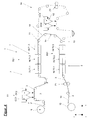
- FIGS. 2a to 2c shows the FIG. 3 a concrete constructive implementation in a schematic simplified representation of an embodiment according to FIG. 2b ,
- the same reference numerals are used for the same elements.
- a coordinate system for clarification of the individual directions within the device 1 is given again.
- the arrangement of the two functional layers forming units 7 and 8 also takes place in different vertical planes, wherein the extension in the axial direction preferably takes place free of offset from one another.
- the arrangement of the drying section TS2 takes place in the bypass to the application device A2 of the second functional layer-forming unit 8. This results in the need for further web guiding areas to allow a guide of the carrier web T in the different modes in different directions through the drying line TS2.
- the web guide path IIa is provided, which describes the area in which the applicator A2 is arranged, while the web guide path in the bypass area to the applicator A2 is designated IIb.
- a further third web guide path III is provided, which in a mode of operation in which a layer 8 is also applied via the second functional layer forming unit to the carrier web T, guides the carrier web T through the dry line TS2 in FIG opposite direction to the passage when bypassing the applicator A2 to the take-up device 12 allows.
- FIG. 3 illustrates here by means of a continuous line the web guide within the device 1 in the first mode, that is, for applying a multiple line on the top 2 of the carrier web T in the form of the fibrous web F and the utilization of the drying capacities of both functional layers forming units 7 and 8.
- This embodiment uses while the web guide areas I and IIb from. The web guiding areas IIa and III are not considered.
- the fibrous web F is guided via the web guiding path IIa and subsequently via the drying section TS2 and the web guiding path III to the winding device 12.
- the fibrous web F undergoes this process a repeated change of direction.
- the individual guide elements and guide rollers are arranged in such a way that they enable a direction reversal or change between the first drying section TS1 of the unit 7 and the application device A2 of the second functional layer-forming unit 8. Subsequent to the application device A2, the drying section TS2 is traversed in the opposite direction and, after another reversal of direction following the drying section TS2, returned to the winding device 12.
- corresponding means for carrier web guide in the form of guide rollers and guide rollers are provided, which allow these individual changes in direction.
- corresponding pulling devices Z1 to Z3 are required.
- Another traction device Z3 is arranged downstream of the drying section TS2 in the web path III.
- the individual drying sections TS1 and TS2 contain at least one drying device, preferably a plurality of series-connected drying devices HLT1.1 to HLT1.3 and HLT2.1 to HLT2.3, which are operated with hot air that is gas- or steam-heated.
- the in the FIG. 3 shown drying devices are designed such that between them, the leadership of the carrier web T via guide rollers.
- the arrangement of the individual drying sections TS1 of the first functional layer-forming unit 7 and TS2 of the second functional layer-forming unit 8 preferably takes place in the form of tunnel driers free of the interposition of guide rollers connected in series in two vertical planes.
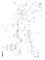
- the execution according to FIG. 4 corresponds essentially to the embodiment according to FIG. 2a in which the guide in the bypass is free of an arrangement of the drying section TS2 and the drying section TS2 is arranged downstream of the branch 11 or the combination 13, as it were.
- This design allows a very space-saving arrangement in the axial direction.
- the applicator A2 of the second functional layer-forming unit 8 is arranged in the axial direction offset from the extension of the first functional layer-forming unit 7.
- FIG. 4 shown theoretically possible structural design is essentially by in the FIG. 2a described pathways I, IIa, IIb characterized.
- a guide either via further guide rollers to the next application device A2, here with the application nozzles CC3 and CC4, wherein the guide is made so that now the bottom is coated and subsequently to the drying section TS2 Winding device 12 is guided.
- guidance is via the first mode Part of a requiredPoltrockenumble, which is formed by the drying section TS1 and also taking advantage of the drying capacity of the second functional layer forming unit 8 via the drying line TS2 bypassing the applicator A2, in particular with the application nozzles CC3 and CC4.
- the web turning device 15 is preferably arranged between the coupling of the first functional layer-forming device 7 and the second functional layer-forming device 8 in a bypass.
- This is designated 16 here.
- FIG. 5 clarifies this in a further development of the execution accordingly FIG. 4 an embodiment according to the in FIG. 2a described basic principle with additional web turning device 15.
- a further web guiding region IV is provided here, which forms the bypass 16.
- the functional layers forming units 7 and 8 are arranged offset from each other in the vertical direction, so that the guidance of the carrier web T takes place in these oppositely directed.
- the first functional layer forming unit 7 is followed in the web guide to a branch 11, which is connected to the web guide portion IIa, IIb, in which the application devices A2 of the second functional layer-forming unit 8 are arranged and also a bypass to this, which is a partial area the Bru arrangementsweges IIb forms.
- the drying section TS2 is also arranged here after the merge 13 in the web guide path IIb.
- multi-layer curtain applicator By providing in the second functional layer forming unit 8 multi-layer curtain applicator with the application nozzles CC3, CC4 results in a variety of modes of operation for one-sided coated carrier webs T in the FIGS. 6a to 6d while double-coated Subahnen the individual process steps in the FIGS. 7a to 7c are shown.
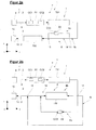
- FIG. 6a illustrates exemplified based on a signal flow diagram, the individual acting on the carrier web T functional units that are run through successively.
- activation of the application device A1 in the form of the multi-layer curtain application unit with the application nozzles CC1 or CC2 takes place for the one-sided application on the upper side 2 of the carrier web T, here by way of example CC1.
- CC2 is disabled in this case.
- the drying devices HLT2.1 and 2.2 of the second drying section TS2 need not be activated.
- FIG. 6b1 illustrated by means of a signal flow diagram, the individual process steps for generating a multiple job, in particular a double coating.
- an application with the application nozzles CC1 and CC2 is possible, CC1 applying the thermosensitive layer and by way of example the required cover layer 5 in the form of the protective layer being produced by means of CC2.
- the entire coating is applied over the two drying sections TS1 and TS2 of the two functional layer-forming units to the required dry content.
- the individual layers are produced by the application devices A1, A2 of both functional layer-forming units 7 and 8.
- one of the two application devices of the first functional layer-forming units 7 is deactivated, preferably CC2, and the order of the thermo-sensitive layer is preferably done by CC1.
- the web After passing through the drying section TS1, the web is turned over the web turning device 15 before being fed to the application device of the second functional layer-forming unit 8, so that in turn the top side 2 can be provided with a coating over the individual application nozzles CC3 or CC4.
- One of the two devices assumes this function and subsequently the thus-coated carrier web T is fed to the drying section TS2 and passes through the two hot air dryers HLT2.1 and HLT2.2.
- FIG. 6b2 extended to the effect that in one of the two functional layers forming units 7 or 8, a further application device is also active.
- FIG. 6c by means of the application nozzles CC1 and CC2, after passing through the drying section TS1 and the web turning device 15 by means of the nozzles CC3 or CC4 and passing through the drying section TS2, a triple-coated fibrous web 10 is produced.
- the further nozzle CC4 of the second functional layer-forming unit 8 can also be activated, as in FIG FIG. 6d played.
- thermo-sensitive layer 4 is applied to the upper side 2. This is passed over the drying line 1 and spent on the required dry content, in order subsequently to obtain at the bottom 3, the required further thermosensitive layer 6, which is spent in the downstream drying section TS2 to the required dry content.
- a carrier web T coated on both sides with a double layer on one side the first example is shown here by way of example Functional layer forming unit 7 is activated and applied to the thermosensitive layer 4, the required cover layer 5, wherein the two layers of the drying section TS1 are supplied, dried over this and then the bottom 3 coated by the applicator A2 of the second functional layer forming unit 8 and is dried over the drying section TS2, wherein in this further also a drying of the multi-layer takes place at the top 2.
- FIG. 7c clarified in a further development according to FIG. 7b the additional activation of the second application nozzle CC4 of the second functional layer-forming unit 8.
- the inventive solution is here not limited to these embodiments.
- the basic configuration is based on two functional layers forming units 7, 8, over which a very large number of multiple coatings can be achieved.
- the only requirement is the arrangement of the second functional layer-forming unit 8 in such a way that the applicator A2 of the second functional layer-forming unit can be bypassed in the bypass.
Landscapes
- Paper (AREA)
- Coating Apparatus (AREA)
Applications Claiming Priority (1)
| Application Number | Priority Date | Filing Date | Title |
|---|---|---|---|
| DE102008041422A DE102008041422A1 (de) | 2008-08-21 | 2008-08-21 | Vorrichtung zur Erzeugung von beschichteten Papier-, Karton- oder anderen Faserstoffbahnen mit mindestens einer thermosensitiven Schicht und Verfahren zum Betreiben einer derartigen Vorrichtung |
Publications (2)
| Publication Number | Publication Date |
|---|---|
| EP2157238A1 true EP2157238A1 (fr) | 2010-02-24 |
| EP2157238B1 EP2157238B1 (fr) | 2011-08-17 |
Family
ID=41276560
Family Applications (1)
| Application Number | Title | Priority Date | Filing Date |
|---|---|---|---|
| EP09168032A Not-in-force EP2157238B1 (fr) | 2008-08-21 | 2009-08-18 | Dispositif de production de bandes de matière fibreuse de papier, de carton ou autres revêtues dotées au moins d'une couche thermosensible et procédé de fonctionnement d'un tel dispositif |
Country Status (5)
| Country | Link |
|---|---|
| US (1) | US20100055333A1 (fr) |
| EP (1) | EP2157238B1 (fr) |
| AT (1) | ATE520824T1 (fr) |
| DE (1) | DE102008041422A1 (fr) |
| ES (1) | ES2369173T3 (fr) |
Cited By (1)
| Publication number | Priority date | Publication date | Assignee | Title |
|---|---|---|---|---|
| WO2011151238A1 (fr) * | 2010-06-02 | 2011-12-08 | Voith Patent Gmbh | Procédé de production d'une bande fibreuse multicouche enduite |
Families Citing this family (3)
| Publication number | Priority date | Publication date | Assignee | Title |
|---|---|---|---|---|
| DE102008041419A1 (de) * | 2008-08-21 | 2010-02-25 | Voith Patent Gmbh | Vorrichtung zur Erzeugung von beschichteten Papier-, Karton- oder anderen Faserstoffbahnen mit zumindest einer thermosensitiven Schicht und Verfahren zum Betreiben einer derartigen Vorrichtung |
| DE202010016479U1 (de) | 2010-12-10 | 2011-02-17 | Voith Patent Gmbh | Auftragsvorrichtung |
| CN112871529B (zh) * | 2021-01-11 | 2021-12-17 | 温州医科大学附属第二医院(温州医科大学附属育英儿童医院) | 一种自动化雾化涂膜仪 |
Citations (3)
| Publication number | Priority date | Publication date | Assignee | Title |
|---|---|---|---|---|
| WO2004001133A2 (fr) * | 2002-06-24 | 2003-12-31 | Voith Paper Patent Gmbh | Dispositif d'enduction des deux faces d'une bande notamment de papier ou de carton et de sechage de cette bande |
| EP1538262A1 (fr) * | 2003-12-01 | 2005-06-08 | Voith Paper Patent GmbH | Installation de revetment double face |
| EP1736321A1 (fr) * | 2005-06-22 | 2006-12-27 | Voith Patent GmbH | Procédé pour la fabrication d'un papier thermique |
Family Cites Families (3)
| Publication number | Priority date | Publication date | Assignee | Title |
|---|---|---|---|---|
| DE4313628A1 (de) * | 1993-04-27 | 1993-09-30 | Voith Gmbh J M | Einrichtung zum wahlweisen Behandeln von laufenden Bahnen |
| DE4420242A1 (de) * | 1994-06-10 | 1995-01-05 | Voith Gmbh J M | Einrichtung zur wahlweisen Behandlung einer laufenden Bahn |
| US7563326B2 (en) * | 2002-06-24 | 2009-07-21 | Voith Paper Patent Gmbh | Device for coating and drying both sides of a material web of paper or board |
-
2008
- 2008-08-21 DE DE102008041422A patent/DE102008041422A1/de not_active Withdrawn
-
2009
- 2009-08-18 US US12/542,907 patent/US20100055333A1/en not_active Abandoned
- 2009-08-18 EP EP09168032A patent/EP2157238B1/fr not_active Not-in-force
- 2009-08-18 ES ES09168032T patent/ES2369173T3/es active Active
- 2009-08-18 AT AT09168032T patent/ATE520824T1/de active
Patent Citations (3)
| Publication number | Priority date | Publication date | Assignee | Title |
|---|---|---|---|---|
| WO2004001133A2 (fr) * | 2002-06-24 | 2003-12-31 | Voith Paper Patent Gmbh | Dispositif d'enduction des deux faces d'une bande notamment de papier ou de carton et de sechage de cette bande |
| EP1538262A1 (fr) * | 2003-12-01 | 2005-06-08 | Voith Paper Patent GmbH | Installation de revetment double face |
| EP1736321A1 (fr) * | 2005-06-22 | 2006-12-27 | Voith Patent GmbH | Procédé pour la fabrication d'un papier thermique |
Non-Patent Citations (1)
| Title |
|---|
| LA PAPETERIE, vol. 275, April 2006 (2006-04-01), pages 6 - 14 |
Cited By (1)
| Publication number | Priority date | Publication date | Assignee | Title |
|---|---|---|---|---|
| WO2011151238A1 (fr) * | 2010-06-02 | 2011-12-08 | Voith Patent Gmbh | Procédé de production d'une bande fibreuse multicouche enduite |
Also Published As
| Publication number | Publication date |
|---|---|
| ATE520824T1 (de) | 2011-09-15 |
| EP2157238B1 (fr) | 2011-08-17 |
| DE102008041422A1 (de) | 2010-02-25 |
| US20100055333A1 (en) | 2010-03-04 |
| ES2369173T3 (es) | 2011-11-28 |
Similar Documents
| Publication | Publication Date | Title |
|---|---|---|
| EP1861207B1 (fr) | Dispositif d'application | |
| DE102007002980A1 (de) | Klebstoffauftrageinrichtung für eine papier- oder kartonverarbeitende Maschine | |
| WO2002018142A1 (fr) | Installation pour produire en continu des bandes textiles imprimees, notamment des bandes d'etiquettes imprimees | |
| EP2157238B1 (fr) | Dispositif de production de bandes de matière fibreuse de papier, de carton ou autres revêtues dotées au moins d'une couche thermosensible et procédé de fonctionnement d'un tel dispositif | |
| EP2157240B1 (fr) | Dispositif d'application de rideau | |
| EP2146003A2 (fr) | Unité d'application de rideau | |
| DE102014207709B4 (de) | Verfahren zum Bedrucken eines Bedruckstoffs mittels wenigstens eines Tintenstrahldruckkopfes | |
| EP2157239B1 (fr) | Dispositif de production de bandes de matière fibreuse de papier, de carton ou autres revêtues dotées au moins d'une couche thermosensible et procédé de fonctionnement d'un tel dispositif | |
| DE102018117699A1 (de) | Verfahren und Vorrichtung zum beidseitigen Bedrucken eines Aufzeichnungsträgers | |
| DE102010003322A1 (de) | Verfahren und Vorrichtung zum Auftragen wenigstens einer Schicht eines Auftragsmediums auf die Oberfläche einer laufenden Papier-, Karton- oder anderen Faserstoffbahn | |
| DE102016203528A1 (de) | Verfahren und Vorrichtung zur Herstellung eines Dekorsubstrates sowie Verfahren zur Herstellung eines Laminats | |
| DE69028878T2 (de) | Bandbreiteneinstellvorrichtung für Vorhangsbeschichtungen | |
| EP1862302A2 (fr) | Presse rotative dotée d'un dispositif de séchage | |
| DE102009021164A1 (de) | Verfahren und Vorrichtung zum Imprägnieren/Beschichten einer Bahn | |
| DE4008044C2 (fr) | ||
| EP1782891B1 (fr) | Méthode et appareil pour le dépôt d'au moins deux couches de peinture sur la surface d'une bande continue, en particulier d'une bande continue de papier ou de carton | |
| EP1964970A2 (fr) | Procédé de fabrication d'une bande de papier, de carton ou autre matière fibreuse revêtue | |
| EP2529049A1 (fr) | Machine à papier thermosensible ou à papier autocopiant et procédé de fabrication de papier thermosensible ou papier autocopiant | |
| WO2005059250A1 (fr) | Mecanisme de coucheuse a nappe | |
| WO2023237253A1 (fr) | Procédé de fonctionnement d'un système comprenant une onduleuse et une machine d'impression, et système | |
| EP2070600B1 (fr) | Procédé de revêtement d'une bande en mouvement de papier, de carton ou d'une autre matière fibreuse à l'aide d'un revêtement de rideau | |
| EP2596171A1 (fr) | Coucheuse rideau | |
| DE102025102258B3 (de) | Auftragsvorrichtung zum Auftragen eines Auftragsstoffs auf einen Bedruckstoff und Druckgerät zum Bedrucken eines Bedruckstoffs, das eine solche Auftragsvorrichtung aufweist | |
| DE3315459A1 (de) | Beschichtungsapparat | |
| DE19721706C2 (de) | Verfahren und Vorrichtung zum Kaschieren |
Legal Events
| Date | Code | Title | Description |
|---|---|---|---|
| PUAI | Public reference made under article 153(3) epc to a published international application that has entered the european phase |
Free format text: ORIGINAL CODE: 0009012 |
|
| AK | Designated contracting states |
Kind code of ref document: A1 Designated state(s): AT BE BG CH CY CZ DE DK EE ES FI FR GB GR HR HU IE IS IT LI LT LU LV MC MK MT NL NO PL PT RO SE SI SK SM TR |
|
| 17P | Request for examination filed |
Effective date: 20100824 |
|
| 17Q | First examination report despatched |
Effective date: 20100924 |
|
| GRAP | Despatch of communication of intention to grant a patent |
Free format text: ORIGINAL CODE: EPIDOSNIGR1 |
|
| GRAS | Grant fee paid |
Free format text: ORIGINAL CODE: EPIDOSNIGR3 |
|
| GRAA | (expected) grant |
Free format text: ORIGINAL CODE: 0009210 |
|
| AK | Designated contracting states |
Kind code of ref document: B1 Designated state(s): AT BE BG CH CY CZ DE DK EE ES FI FR GB GR HR HU IE IS IT LI LT LU LV MC MK MT NL NO PL PT RO SE SI SK SM TR |
|
| REG | Reference to a national code |
Ref country code: GB Ref legal event code: FG4D Free format text: NOT ENGLISH |
|
| REG | Reference to a national code |
Ref country code: CH Ref legal event code: EP |
|
| REG | Reference to a national code |
Ref country code: IE Ref legal event code: FG4D Free format text: LANGUAGE OF EP DOCUMENT: GERMAN |
|
| REG | Reference to a national code |
Ref country code: DE Ref legal event code: R096 Ref document number: 502009001122 Country of ref document: DE Effective date: 20111117 |
|
| REG | Reference to a national code |
Ref country code: ES Ref legal event code: FG2A Ref document number: 2369173 Country of ref document: ES Kind code of ref document: T3 Effective date: 20111128 |
|
| PGFP | Annual fee paid to national office [announced via postgrant information from national office to epo] |
Ref country code: FR Payment date: 20110912 Year of fee payment: 3 Ref country code: ES Payment date: 20110926 Year of fee payment: 3 |
|
| REG | Reference to a national code |
Ref country code: NL Ref legal event code: VDEP Effective date: 20110817 |
|
| PG25 | Lapsed in a contracting state [announced via postgrant information from national office to epo] |
Ref country code: MT Free format text: LAPSE BECAUSE OF FAILURE TO SUBMIT A TRANSLATION OF THE DESCRIPTION OR TO PAY THE FEE WITHIN THE PRESCRIBED TIME-LIMIT Effective date: 20110817 |
|
| LTIE | Lt: invalidation of european patent or patent extension |
Effective date: 20110817 |
|
| PG25 | Lapsed in a contracting state [announced via postgrant information from national office to epo] |
Ref country code: IS Free format text: LAPSE BECAUSE OF FAILURE TO SUBMIT A TRANSLATION OF THE DESCRIPTION OR TO PAY THE FEE WITHIN THE PRESCRIBED TIME-LIMIT Effective date: 20111217 Ref country code: NO Free format text: LAPSE BECAUSE OF FAILURE TO SUBMIT A TRANSLATION OF THE DESCRIPTION OR TO PAY THE FEE WITHIN THE PRESCRIBED TIME-LIMIT Effective date: 20111117 Ref country code: PT Free format text: LAPSE BECAUSE OF FAILURE TO SUBMIT A TRANSLATION OF THE DESCRIPTION OR TO PAY THE FEE WITHIN THE PRESCRIBED TIME-LIMIT Effective date: 20111219 Ref country code: LT Free format text: LAPSE BECAUSE OF FAILURE TO SUBMIT A TRANSLATION OF THE DESCRIPTION OR TO PAY THE FEE WITHIN THE PRESCRIBED TIME-LIMIT Effective date: 20110817 Ref country code: NL Free format text: LAPSE BECAUSE OF FAILURE TO SUBMIT A TRANSLATION OF THE DESCRIPTION OR TO PAY THE FEE WITHIN THE PRESCRIBED TIME-LIMIT Effective date: 20110817 Ref country code: SE Free format text: LAPSE BECAUSE OF FAILURE TO SUBMIT A TRANSLATION OF THE DESCRIPTION OR TO PAY THE FEE WITHIN THE PRESCRIBED TIME-LIMIT Effective date: 20110817 |
|
| BERE | Be: lapsed |
Owner name: VOITH PATENT G.M.B.H. Effective date: 20110831 |
|
| PG25 | Lapsed in a contracting state [announced via postgrant information from national office to epo] |
Ref country code: CY Free format text: LAPSE BECAUSE OF FAILURE TO SUBMIT A TRANSLATION OF THE DESCRIPTION OR TO PAY THE FEE WITHIN THE PRESCRIBED TIME-LIMIT Effective date: 20110817 Ref country code: LV Free format text: LAPSE BECAUSE OF FAILURE TO SUBMIT A TRANSLATION OF THE DESCRIPTION OR TO PAY THE FEE WITHIN THE PRESCRIBED TIME-LIMIT Effective date: 20110817 Ref country code: SI Free format text: LAPSE BECAUSE OF FAILURE TO SUBMIT A TRANSLATION OF THE DESCRIPTION OR TO PAY THE FEE WITHIN THE PRESCRIBED TIME-LIMIT Effective date: 20110817 Ref country code: PL Free format text: LAPSE BECAUSE OF FAILURE TO SUBMIT A TRANSLATION OF THE DESCRIPTION OR TO PAY THE FEE WITHIN THE PRESCRIBED TIME-LIMIT Effective date: 20110817 Ref country code: GR Free format text: LAPSE BECAUSE OF FAILURE TO SUBMIT A TRANSLATION OF THE DESCRIPTION OR TO PAY THE FEE WITHIN THE PRESCRIBED TIME-LIMIT Effective date: 20111118 |
|
| REG | Reference to a national code |
Ref country code: IE Ref legal event code: FD4D |
|
| PG25 | Lapsed in a contracting state [announced via postgrant information from national office to epo] |
Ref country code: MC Free format text: LAPSE BECAUSE OF NON-PAYMENT OF DUE FEES Effective date: 20110831 |
|
| PG25 | Lapsed in a contracting state [announced via postgrant information from national office to epo] |
Ref country code: IE Free format text: LAPSE BECAUSE OF FAILURE TO SUBMIT A TRANSLATION OF THE DESCRIPTION OR TO PAY THE FEE WITHIN THE PRESCRIBED TIME-LIMIT Effective date: 20110817 Ref country code: SK Free format text: LAPSE BECAUSE OF FAILURE TO SUBMIT A TRANSLATION OF THE DESCRIPTION OR TO PAY THE FEE WITHIN THE PRESCRIBED TIME-LIMIT Effective date: 20110817 Ref country code: CZ Free format text: LAPSE BECAUSE OF FAILURE TO SUBMIT A TRANSLATION OF THE DESCRIPTION OR TO PAY THE FEE WITHIN THE PRESCRIBED TIME-LIMIT Effective date: 20110817 |
|
| PG25 | Lapsed in a contracting state [announced via postgrant information from national office to epo] |
Ref country code: RO Free format text: LAPSE BECAUSE OF FAILURE TO SUBMIT A TRANSLATION OF THE DESCRIPTION OR TO PAY THE FEE WITHIN THE PRESCRIBED TIME-LIMIT Effective date: 20110817 Ref country code: BE Free format text: LAPSE BECAUSE OF NON-PAYMENT OF DUE FEES Effective date: 20110831 Ref country code: EE Free format text: LAPSE BECAUSE OF FAILURE TO SUBMIT A TRANSLATION OF THE DESCRIPTION OR TO PAY THE FEE WITHIN THE PRESCRIBED TIME-LIMIT Effective date: 20110817 |
|
| PLBE | No opposition filed within time limit |
Free format text: ORIGINAL CODE: 0009261 |
|
| STAA | Information on the status of an ep patent application or granted ep patent |
Free format text: STATUS: NO OPPOSITION FILED WITHIN TIME LIMIT |
|
| PG25 | Lapsed in a contracting state [announced via postgrant information from national office to epo] |
Ref country code: DK Free format text: LAPSE BECAUSE OF FAILURE TO SUBMIT A TRANSLATION OF THE DESCRIPTION OR TO PAY THE FEE WITHIN THE PRESCRIBED TIME-LIMIT Effective date: 20110817 |
|
| 26N | No opposition filed |
Effective date: 20120521 |
|
| PG25 | Lapsed in a contracting state [announced via postgrant information from national office to epo] |
Ref country code: HR Free format text: LAPSE BECAUSE OF FAILURE TO SUBMIT A TRANSLATION OF THE DESCRIPTION OR TO PAY THE FEE WITHIN THE PRESCRIBED TIME-LIMIT Effective date: 20120201 |
|
| REG | Reference to a national code |
Ref country code: DE Ref legal event code: R097 Ref document number: 502009001122 Country of ref document: DE Effective date: 20120521 |
|
| PGFP | Annual fee paid to national office [announced via postgrant information from national office to epo] |
Ref country code: IT Payment date: 20120630 Year of fee payment: 4 |
|
| PGFP | Annual fee paid to national office [announced via postgrant information from national office to epo] |
Ref country code: FI Payment date: 20120813 Year of fee payment: 4 |
|
| PGFP | Annual fee paid to national office [announced via postgrant information from national office to epo] |
Ref country code: DE Payment date: 20120822 Year of fee payment: 4 |
|
| PG25 | Lapsed in a contracting state [announced via postgrant information from national office to epo] |
Ref country code: MK Free format text: LAPSE BECAUSE OF FAILURE TO SUBMIT A TRANSLATION OF THE DESCRIPTION OR TO PAY THE FEE WITHIN THE PRESCRIBED TIME-LIMIT Effective date: 20110817 |
|
| PG25 | Lapsed in a contracting state [announced via postgrant information from national office to epo] |
Ref country code: SM Free format text: LAPSE BECAUSE OF FAILURE TO SUBMIT A TRANSLATION OF THE DESCRIPTION OR TO PAY THE FEE WITHIN THE PRESCRIBED TIME-LIMIT Effective date: 20110817 |
|
| REG | Reference to a national code |
Ref country code: FR Ref legal event code: ST Effective date: 20130430 |
|
| PG25 | Lapsed in a contracting state [announced via postgrant information from national office to epo] |
Ref country code: LU Free format text: LAPSE BECAUSE OF NON-PAYMENT OF DUE FEES Effective date: 20110818 |
|
| PG25 | Lapsed in a contracting state [announced via postgrant information from national office to epo] |
Ref country code: BG Free format text: LAPSE BECAUSE OF FAILURE TO SUBMIT A TRANSLATION OF THE DESCRIPTION OR TO PAY THE FEE WITHIN THE PRESCRIBED TIME-LIMIT Effective date: 20111117 |
|
| PG25 | Lapsed in a contracting state [announced via postgrant information from national office to epo] |
Ref country code: FR Free format text: LAPSE BECAUSE OF NON-PAYMENT OF DUE FEES Effective date: 20120831 |
|
| PG25 | Lapsed in a contracting state [announced via postgrant information from national office to epo] |
Ref country code: TR Free format text: LAPSE BECAUSE OF FAILURE TO SUBMIT A TRANSLATION OF THE DESCRIPTION OR TO PAY THE FEE WITHIN THE PRESCRIBED TIME-LIMIT Effective date: 20110817 |
|
| REG | Reference to a national code |
Ref country code: ES Ref legal event code: FD2A Effective date: 20131018 |
|
| PG25 | Lapsed in a contracting state [announced via postgrant information from national office to epo] |
Ref country code: ES Free format text: LAPSE BECAUSE OF NON-PAYMENT OF DUE FEES Effective date: 20120819 Ref country code: HU Free format text: LAPSE BECAUSE OF FAILURE TO SUBMIT A TRANSLATION OF THE DESCRIPTION OR TO PAY THE FEE WITHIN THE PRESCRIBED TIME-LIMIT Effective date: 20110817 |
|
| PG25 | Lapsed in a contracting state [announced via postgrant information from national office to epo] |
Ref country code: HR Free format text: LAPSE BECAUSE OF FAILURE TO SUBMIT A TRANSLATION OF THE DESCRIPTION OR TO PAY THE FEE WITHIN THE PRESCRIBED TIME-LIMIT Effective date: 20110817 |
|
| REG | Reference to a national code |
Ref country code: CH Ref legal event code: PL |
|
| GBPC | Gb: european patent ceased through non-payment of renewal fee |
Effective date: 20130818 |
|
| PG25 | Lapsed in a contracting state [announced via postgrant information from national office to epo] |
Ref country code: DE Free format text: LAPSE BECAUSE OF NON-PAYMENT OF DUE FEES Effective date: 20140301 Ref country code: FI Free format text: LAPSE BECAUSE OF NON-PAYMENT OF DUE FEES Effective date: 20130818 Ref country code: LI Free format text: LAPSE BECAUSE OF NON-PAYMENT OF DUE FEES Effective date: 20130831 Ref country code: CH Free format text: LAPSE BECAUSE OF NON-PAYMENT OF DUE FEES Effective date: 20130831 |
|
| PG25 | Lapsed in a contracting state [announced via postgrant information from national office to epo] |
Ref country code: IT Free format text: LAPSE BECAUSE OF NON-PAYMENT OF DUE FEES Effective date: 20130818 |
|
| REG | Reference to a national code |
Ref country code: DE Ref legal event code: R119 Ref document number: 502009001122 Country of ref document: DE Effective date: 20140301 |
|
| PG25 | Lapsed in a contracting state [announced via postgrant information from national office to epo] |
Ref country code: GB Free format text: LAPSE BECAUSE OF NON-PAYMENT OF DUE FEES Effective date: 20130818 |
|
| REG | Reference to a national code |
Ref country code: AT Ref legal event code: MM01 Ref document number: 520824 Country of ref document: AT Kind code of ref document: T Effective date: 20140818 |
|
| PG25 | Lapsed in a contracting state [announced via postgrant information from national office to epo] |
Ref country code: AT Free format text: LAPSE BECAUSE OF NON-PAYMENT OF DUE FEES Effective date: 20140818 |