EP2157272A2 - Cadre pour portes, fenêtres et similaires - Google Patents
Cadre pour portes, fenêtres et similaires Download PDFInfo
- Publication number
- EP2157272A2 EP2157272A2 EP09447037A EP09447037A EP2157272A2 EP 2157272 A2 EP2157272 A2 EP 2157272A2 EP 09447037 A EP09447037 A EP 09447037A EP 09447037 A EP09447037 A EP 09447037A EP 2157272 A2 EP2157272 A2 EP 2157272A2
- Authority
- EP
- European Patent Office
- Prior art keywords
- frame
- post
- additional post
- main frame
- ventilation
- Prior art date
- Legal status (The legal status is an assumption and is not a legal conclusion. Google has not performed a legal analysis and makes no representation as to the accuracy of the status listed.)
- Withdrawn
Links
Images


Classifications
-
- E—FIXED CONSTRUCTIONS
- E06—DOORS, WINDOWS, SHUTTERS, OR ROLLER BLINDS IN GENERAL; LADDERS
- E06B—FIXED OR MOVABLE CLOSURES FOR OPENINGS IN BUILDINGS, VEHICLES, FENCES OR LIKE ENCLOSURES IN GENERAL, e.g. DOORS, WINDOWS, BLINDS, GATES
- E06B7/00—Special arrangements or measures in connection with doors or windows
- E06B7/02—Special arrangements or measures in connection with doors or windows for providing ventilation, e.g. through double windows; Arrangement of ventilation roses
- E06B7/10—Special arrangements or measures in connection with doors or windows for providing ventilation, e.g. through double windows; Arrangement of ventilation roses by special construction of the frame members
Definitions
- the present invention concerns a frame for a window, a door or the like.
- the invention aims a fixed frame which is fixed in a wall opening and which is formed of posts that are mutually connected.
- the surface of the glass panel or the like is selected somewhat smaller than the surface which is surrounded by the frame, such that a ventilation post can be provided above the glass panel.
- a disadvantage is that said ventilation post must be installed simultaneously with the glass panel, and consequently this can only be done at the building site.
- the present invention aims to remedy one or several of the above-mentioned and/or other disadvantages by providing a frame for a window, a door or the like which is formed of mutually connected posts, whereby an additional post is provided on the inside or the outside of the frame by means of a rigid fastening, whereby the additional post, together with the aforesaid frame, in particular called the main frame, forms a secondary frame for mounting a panel or a pivoting or sliding wing, whereby the aforesaid additional post is mounted at a distance from one of the posts of the main frame so as to form a ventilation passage, and whereby the aforesaid additional post continues between two parallel posts of the main frame and is connected to the opposite post of the main frame, which connects the above-mentioned parallel posts, by means of supports which are mounted at a distance from one another.
- An advantage is that the secondary frame of the window, the door or the like can be mounted in the manner that has been used up to now for conventional windows without any ventilation.
- An advantage related thereto is that the frame can be fixed in the wall opening on all sides, such that a firm anchorage is obtained.
- Another advantage is that the additional post can be put in the main frame before mounting the main frame.
- controllable ventilation means consisting for example of one or several ventilation units which can be either or not removed, whereby these ventilation means may be self-regulating.
- the supports are made as separate elements, such that a modular system is obtained, whereby the number of supports and the position of these supports can be adjusted as a function of the dimensions of the ventilation units to be applied and/or of the passage in the post.
- the supports are thereby provided in a sliding and/or clamping manner in a guide in the additional post.
- Figure 1 schematically represents a frame 1 for a window, a door or the like, which frame 1 is formed of mutually connected posts 2 in the known manner.
- the aforesaid frame is built of two pairs of parallel posts 3-4 which have been mitred, such that they can be provided within a rectangular wall opening.
- this main frame 1 is provided with an additional post 5, which together with the main frame 1 forms a secondary frame 6.
- this secondary frame forms a smaller inner frame.
- the posts 2 of the main frame 1 and the additional post 5 are provided with an inwardly protruding rib 7, against which a glass panel 8 or another panel may rest, as shown in figure 2 .
- the additional post 5 is mounted at a distance from a post 2, i.e. in the given embodiment of the figures the upper post 9 of the main frame 1, so as to form a ventilation passage 10.
- the additional post 5 continues between two parallel posts 3 of the main frame 1, and the additional post 5 is connected to said upper post 9 of the main frame 1 by means of one or several supports 11.
- supports 11 are mounted at a distance from one another, and the supports 11 are firmly fixed to a post 9 of the main frame 1, for example by means of screws 12.
- the supports are not part of the frame, but that they are made as separate elements so as to obtain a modular system.
- the supports 11 can be provided in a sliding manner in relation to the additional post 5 in a guide 13 provided to that end.
- the supports 11 may be firmly fixed in a guide 13 of the additional post 5 provided to that end, and they may be provided in a clamping manner in a guide of the opposite post.
- the supports 11 may also be arranged in a clamping manner or they may be mounted upside down.
- each of the above-mentioned supports 11 is formed of a body 14 which is provided with a foot 15 on the bottom side extending at an angle in relation to the body 14.
- the above-mentioned foot 15 has a shape which is fit to cooperate with the guide 13 of the additional post 5.
- said guide 13 consists of two standing ribs 16 on the additional post 5, whereby the far ends 17 of the ribs 16 are at right angles to the ribs 16.
- the above-mentioned ventilation passage 10 can be sealed on the inside by means of a valve 18 arranged in a revolving manner between a closed and an open position, which valve 18 is represented in the section of figures 2 and 3 , in a closed and open position respectively.
- the valve 18 as represented is hinge-mounted by means of a hinge 19, provided on a foot 15 of the support 11, for example by means of a snap-in system.
- hinge 19 in the additional post 5 and/or to connect it to the support 11 in any way whatsoever, such as for example by means of screws.
- the valve 18 may be provided with a protruding cam 20 which may be in turn connected to a control element, not represented in the figures, such as for example a rod or the like.
- the above-mentioned ventilation passage 10 is covered with a grid 21 on the other side, i.e. on the outside.
- the invention can also be realised without a grid 21.
- said grid 21 has been integrated in the additional post 5.
- the grid 21 can also be mounted on a post of the frame 1.
- the grid 21 can be provided with an outwardly protruding drain post 22 which is part of the grid 21.
- the drain post 22 can be provided as a separate post and loose from the additional post 5.
- the above-mentioned side of the ventilation passage 10 may be covered with a gauze.
- At least one removable ventilation unit 23 is provided in the space between the main frame 1 and the additional post 5.
- the entire width of the space will be preferably filled with a series of ventilation units 23, whereby the width of each ventilation unit 23 mainly corresponds to the distance between the successive supports 11, such that the ventilation units 23 can be provided between the supports 11 or removed from in between them, for example for maintenance or repair activities.
- each of the above-mentioned ventilation units 23 is provided with fastening elements which snap in behind one or several of the edges, not represented in the figures, which define the ventilation passage.
- the ventilation unit 23 may be either or not made as a self-regulating ventilation unit 23, such that a constant free flow of air is obtained.
- the mounting of the frame 1 according to the invention is very simple and as follows.
- the frame 1 is assembled in a traditional manner with the ventilation units 23.
- the assembled frame is placed in the wall opening, after which the glass panel 8 can be placed.
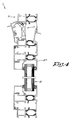
- Figure 4 shows an alternative embodiment whereby the glass panel 8 is not mounted directly in the fixed frame 1 as in figures 1 and 2 , but whereby the glass panel 8 is provided in a wing 24 provided in a pivoting manner in an analogously fixed frame as that of figures 1 and 2 .
- Figure 5 shows another alternative embodiment to be applied in a composed element or the like.
- Figure 6 shows yet another alternative embodiment related to a sliding door which is built-in in a fixed frame with an additional post so as to form an additional space to mount the ventilation units in.
- the additional post 5 is hereby provided on the outside of the frame 1, and the secondary frame thus forms an outer frame which is larger than the main frame 1.
- ventilation units must not be necessarily made as removable cassettes, but that they may also be built-in as fixed ventilation units or elements.
Landscapes
- Engineering & Computer Science (AREA)
- Civil Engineering (AREA)
- Structural Engineering (AREA)
- Specific Sealing Or Ventilating Devices For Doors And Windows (AREA)
Applications Claiming Priority (1)
| Application Number | Priority Date | Filing Date | Title |
|---|---|---|---|
| BE2008/0443A BE1018242A3 (nl) | 2008-08-12 | 2008-08-12 | Kader voor een raam, een deur of dergelijke. |
Publications (2)
| Publication Number | Publication Date |
|---|---|
| EP2157272A2 true EP2157272A2 (fr) | 2010-02-24 |
| EP2157272A3 EP2157272A3 (fr) | 2013-04-03 |
Family
ID=40510436
Family Applications (1)
| Application Number | Title | Priority Date | Filing Date |
|---|---|---|---|
| EP09447037A Withdrawn EP2157272A3 (fr) | 2008-08-12 | 2009-08-07 | Cadre pour portes, fenêtres et similaires |
Country Status (2)
| Country | Link |
|---|---|
| EP (1) | EP2157272A3 (fr) |
| BE (1) | BE1018242A3 (fr) |
Cited By (1)
| Publication number | Priority date | Publication date | Assignee | Title |
|---|---|---|---|---|
| EP3263818A1 (fr) * | 2016-06-14 | 2018-01-03 | Erik Wilms | Fenêtre avec unité de ventilation |
Families Citing this family (2)
| Publication number | Priority date | Publication date | Assignee | Title |
|---|---|---|---|---|
| BE1019153A4 (nl) * | 2010-01-21 | 2012-04-03 | Reynaers Aluminium Nv | Ventilatie-eenheid voor een raam, een deur of dergelijke. |
| CN110513000A (zh) * | 2019-08-26 | 2019-11-29 | 四川金秋新型建材有限公司 | 一种推拉门窗扇 |
Family Cites Families (3)
| Publication number | Priority date | Publication date | Assignee | Title |
|---|---|---|---|---|
| GB1503484A (en) * | 1973-11-14 | 1978-03-08 | Duerden P | Window frames |
| WO1986001249A1 (fr) * | 1984-08-10 | 1986-02-27 | Keith Allan Brown | Encadrements |
| GB9321852D0 (en) * | 1993-10-22 | 1993-12-15 | Smiths Industries Plc | Assemblies |
-
2008
- 2008-08-12 BE BE2008/0443A patent/BE1018242A3/nl active
-
2009
- 2009-08-07 EP EP09447037A patent/EP2157272A3/fr not_active Withdrawn
Cited By (1)
| Publication number | Priority date | Publication date | Assignee | Title |
|---|---|---|---|---|
| EP3263818A1 (fr) * | 2016-06-14 | 2018-01-03 | Erik Wilms | Fenêtre avec unité de ventilation |
Also Published As
| Publication number | Publication date |
|---|---|
| BE1018242A3 (nl) | 2010-07-06 |
| EP2157272A3 (fr) | 2013-04-03 |
Similar Documents
| Publication | Publication Date | Title |
|---|---|---|
| US4770087A (en) | Garage door ventilator | |
| US6378262B1 (en) | Telescoping louvered window insert | |
| KR102060165B1 (ko) | 유리난간대 및 이를 구비한 창호 | |
| KR101469946B1 (ko) | 창호용 자연환기장치 | |
| EP0741832A1 (fr) | Moustiquaire de fenetre | |
| EP2157272A2 (fr) | Cadre pour portes, fenêtres et similaires | |
| KR101948011B1 (ko) | 미세먼지 필터와 방충망이 구비된 가변형 창틀 | |
| RU2449104C2 (ru) | Двухслойное окно с функцией горизонтальной вентиляции | |
| US20170267071A1 (en) | Door with integrated window and blind | |
| EP3444424B1 (fr) | Carter pour dispositif de ventilation et/ou dispositif écran et procédé de modification d'un carter | |
| US4485589A (en) | Controllable detention window | |
| US20080244999A1 (en) | Frame, in Particular for Window, Door or Facade Elements | |
| PT95864B (pt) | Conjunto de fechamento deslizavel | |
| KR101562171B1 (ko) | 차양각 조절이 가능한 루버창 | |
| EP2951378B1 (fr) | Ensemble de panneaux de volet pour ouvertures architecturales | |
| EP2912250B1 (fr) | Caisson de volet roulant | |
| KR20160120633A (ko) | 창호 시스템 | |
| KR102558132B1 (ko) | 물넘침 방지를 위한 창틀의 분리형 레일 | |
| US5746654A (en) | Ventilator | |
| RU120691U1 (ru) | Вентиляционное устройство | |
| KR101829053B1 (ko) | 창문 구조물 | |
| KR102089623B1 (ko) | 창문형 빗물 차단부재 | |
| CN210105681U (zh) | 一种可拆卸外接防雨百叶窗 | |
| KR101721223B1 (ko) | 갤러리 창호 | |
| KR20170055191A (ko) | 미서기창 창틀프레임에 형성된 배수구멍의 차폐구조 |
Legal Events
| Date | Code | Title | Description |
|---|---|---|---|
| PUAI | Public reference made under article 153(3) epc to a published international application that has entered the european phase |
Free format text: ORIGINAL CODE: 0009012 |
|
| AK | Designated contracting states |
Kind code of ref document: A2 Designated state(s): AT BE BG CH CY CZ DE DK EE ES FI FR GB GR HR HU IE IS IT LI LT LU LV MC MK MT NL NO PL PT RO SE SI SK SM TR |
|
| AX | Request for extension of the european patent |
Extension state: AL BA RS |
|
| PUAL | Search report despatched |
Free format text: ORIGINAL CODE: 0009013 |
|
| AK | Designated contracting states |
Kind code of ref document: A3 Designated state(s): AT BE BG CH CY CZ DE DK EE ES FI FR GB GR HR HU IE IS IT LI LT LU LV MC MK MT NL NO PL PT RO SE SI SK SM TR |
|
| AX | Request for extension of the european patent |
Extension state: AL BA RS |
|
| RIC1 | Information provided on ipc code assigned before grant |
Ipc: E06B 7/10 20060101AFI20130227BHEP |
|
| 17P | Request for examination filed |
Effective date: 20131218 |
|
| RBV | Designated contracting states (corrected) |
Designated state(s): AT BE BG CH CY CZ DE DK EE ES FI FR GB GR HR HU IE IS IT LI LT LU LV MC MK MT NL NO PL PT RO SE SI SK SM TR |
|
| 17Q | First examination report despatched |
Effective date: 20160623 |
|
| GRAP | Despatch of communication of intention to grant a patent |
Free format text: ORIGINAL CODE: EPIDOSNIGR1 |
|
| INTG | Intention to grant announced |
Effective date: 20160915 |
|
| STAA | Information on the status of an ep patent application or granted ep patent |
Free format text: STATUS: GRANT OF PATENT IS INTENDED |
|
| STAA | Information on the status of an ep patent application or granted ep patent |
Free format text: STATUS: THE APPLICATION IS DEEMED TO BE WITHDRAWN |
|
| 18D | Application deemed to be withdrawn |
Effective date: 20170126 |