EP2157289B1 - Öldichtung mit pumpenden Laufrad - Google Patents
Öldichtung mit pumpenden Laufrad Download PDFInfo
- Publication number
- EP2157289B1 EP2157289B1 EP09165854.2A EP09165854A EP2157289B1 EP 2157289 B1 EP2157289 B1 EP 2157289B1 EP 09165854 A EP09165854 A EP 09165854A EP 2157289 B1 EP2157289 B1 EP 2157289B1
- Authority
- EP
- European Patent Office
- Prior art keywords
- seal
- rotating
- component
- impeller
- bearing assembly
- Prior art date
- Legal status (The legal status is an assumption and is not a legal conclusion. Google has not performed a legal analysis and makes no representation as to the accuracy of the status listed.)
- Not-in-force
Links
Images




Classifications
-
- F—MECHANICAL ENGINEERING; LIGHTING; HEATING; WEAPONS; BLASTING
- F01—MACHINES OR ENGINES IN GENERAL; ENGINE PLANTS IN GENERAL; STEAM ENGINES
- F01D—NON-POSITIVE DISPLACEMENT MACHINES OR ENGINES, e.g. STEAM TURBINES
- F01D25/00—Component parts, details, or accessories, not provided for in, or of interest apart from, other groups
- F01D25/18—Lubricating arrangements
- F01D25/183—Sealing means
-
- F—MECHANICAL ENGINEERING; LIGHTING; HEATING; WEAPONS; BLASTING
- F01—MACHINES OR ENGINES IN GENERAL; ENGINE PLANTS IN GENERAL; STEAM ENGINES
- F01D—NON-POSITIVE DISPLACEMENT MACHINES OR ENGINES, e.g. STEAM TURBINES
- F01D11/00—Preventing or minimising internal leakage of working-fluid, e.g. between stages
- F01D11/02—Preventing or minimising internal leakage of working-fluid, e.g. between stages by non-contact sealings, e.g. of labyrinth type
Definitions
- This invention relates generally to gas turbine engine bearing sumps and more particularly to control of oil flow in bearing sumps.
- a gas turbine engine includes one or more shafts which are mounted for rotation in several bearings, usually of the rolling-element type.
- the bearings are enclosed in enclosures called “sumps" which are pressurized and provided with an oil flow for lubrication and cooling.
- sumps enclosures which are pressurized and provided with an oil flow for lubrication and cooling.
- one of the boundaries of the sump will be a dynamic seal between a rotating component of the engine and the engine's stationary structure.
- windage comprising a helical thread and mating rotating surface is frequently used.
- the windage caused by the rotating surface pushes the oil mist away from the interface, causing any oil accumulated within the helical thread to be driven through the thread groove back into the sealed cavity.
- the axial component of windage generated by the air shearing acts as a driving force to keep oil mist away.
- the tangential component of windage pushes oil collected at the bottom of helical thread back into sealed cavity. Windage is a secondary effect of shaft rotation and its effectiveness strongly depends on shaft speed and the radial gap between rotating and stationary parts.
- EP 0,831,204 A1 relates to a gas turbine engine compartment seal and discloses features generally corresponding to the preamble of claim 1 herein.
- the present invention provides a rotating seal incorporating an impeller which moves oil mist away from a seal interface using centrifugal force.
- a rotating seal for a gas turbine engine is provided in accordance with claim 1 herein.
- a bearing assembly for a gas turbine is provided in accordance with claim 6 herein.
- Figure 1 depicts a gas turbine engine 10.
- the engine 10 has a longitudinal axis 11 and includes a fan 12, a low pressure compressor or “booster” 14 and a low pressure turbine (“LPT”) 16 collectively referred to as a "low pressure system”.
- the LPT 16 drives the fan 12 and booster 14 through an inner shaft 18, also referred to as an "LP shaft”.
- the engine 10 also includes a high pressure compressor ("HPC") 20, a combustor 22, and a high pressure turbine (“HPT”) 24, collectively referred to as a "gas generator” or “core”.
- HPT 24 drives the HPC 20 through an outer shaft 26, also referred to as an "HP shaft".
- the high and low pressure systems are operable in a known manner to generate a primary or core flow as well as a fan flow or bypass flow. While the illustrated engine 10 is a high-bypass turbofan engine, the principles described herein are equally applicable to turboprop, turbojet, and turboshaft engines, as well as turbine engines used for other vehicles or in stationary applications.
- the inner and outer shafts 18 and 26 are mounted for rotation in several rolling-element bearings.
- the bearings are located in enclosed portions of the engine 10 referred to as "sumps".
- Figure 2 shows an aft sump 28 of the engine 10 in more detail.
- the aft end 30 of the outer shaft 26 is carried by a bearing 32 which is referred to as the "#4R bearing", denoting its location and type.
- the outer race 34 of the bearing 32 is attached to a static annular frame member 36 of the engine 10.
- the frame member 36 has a main body portion 38 that extends in a generally radial direction.
- a stationary seal arm 40 extends axially aft from the main body portion 38.
- the distal end of the stationary seal arm 40 includes a number of annular seal teeth 42 which extend radially outwards, and at the extreme end, an annular sealing surface 44.
- the aft end 46 of the inner shaft 18 extends aft of the outer shaft 26 and is mounted for rotation in a rear frame structure 48 of the engine by a rolling element bearing 50.
- the inner shaft 18 has a disk 52 extending generally radially outward from it. The disk 52 extends between the inner shaft 18 and the LP turbine 16 (see Figure 1 ) and transmits torque between the LP turbine 16 and the inner shaft 18.
- a rotating seal 54 extends axially forward from the disk 52.
- the rotating seal 54 has a generally frustoconical body with forward and aft ends 56 and 58, and its axis of rotation coincides with that of the engine 10.
- the forward end 56 of the rotating seal 54 includes a radially inward-facing seal pocket 60 which may contain a compliant seal material 62 of a known type such as abradable phenolic resin, a metallic honeycomb structure, a carbon seal, or a brush seal.
- a compliant seal material 62 of a known type such as abradable phenolic resin, a metallic honeycomb structure, a carbon seal, or a brush seal.
- An impeller 64 which is described in more detail below.
- An annular, generally conical inner seal arm 66 extends axially forward from a point aft of the impeller 64. As seen in cross-section, the forward end 56 of the rotating seal 54 and the inner seal arm 66 overlap the stationary seal arm 40 in the axial direction.
- the forward end of the rotating seal 54 overlaps the aft end of the stationary seal arm 40 in the axial direction, and the seal pocket 60 is aligned with the seal teeth 42 in the axial direction, so that they cooperatively form a rotating, non-contact seal interface 68.
- the structure of the sealing components could be reversed; e.g. the rotating seal 54 could include radially-extending seal teeth while the stationary seal arm 40 could include a seal pocket.
- the impeller 64 is positioned adjacent the annular sealing surface 44 of the stationary seal arm 40.
- the outer shaft 26, the inner shaft 18, the disk 52, the stationary seal arm 40, and the rotating seal 54 define a "wet" cavity or “oiled” cavity 70.
- the bearing 32 is supplied with oil from a jet, supply line, or orifice in a known manner to provide lubrication and cooling.
- the interaction of the oil supply and the bearing 32 creates a mist of oil within the wet cavity 70.
- the wet cavity 70 is pressurized, air flow tends to transport the oil mist along a leakage path past the seal interface 68, as depicted by the arrow marked "L” in Figure 2 .
- This condition is worsened at low engine operating speeds when the air pressure in the "dry" cavity 72 adjacent the seal interface 68 is relatively low.
- This leakage causes oil loss which is undesirable from a cost, safety, and pollution standpoint.
- the function of the impeller 64 is to reduce or prevent this leakage.
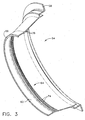
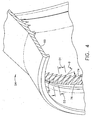
- FIGs 3-6 illustrate the rotating seal 54 in more detail.
- the impeller 64 comprises a ring of impeller blades 74 separated by grooves 76.
- the impeller blades 74 are oriented at an angle "A" to the rotational axis of the rotating seal 54 (see Figure 6 ), and at an angle "B" in the measured from the radial direction, as seen in Figure 4 (i.e. they are tangentially "leaned").
- the angle of the impeller blades 74 can be optimized to ensure adequate axial driving force to keep air/oil mixture away from the sealing interface 68 at all operating conditions, in other words, at all speeds of the rotating seal 54 and at all expected air pressure gradients across the seal interface 68.
- angle A is about 45 degrees and angle B is about 20 degrees
- the impeller blades 74 may be given an airfoil cross-sectional shape.
- the grooves 76 between the impeller blades 74 form a series of radially diverging spiral-shaped pathways.
- the radial depth "D1" of the grooves 76 at the aft edges of the impeller blades 74 is greater than the depth "D2" of the grooves 76 the forward edges of the impeller blades 74.
- the dimensions D1 and D2 may also be conceptualized as the radial span of the impeller blades 74.
- impeller 64 may be used in any sump or location in the engine where it is desirable prevent oil leakage.
Landscapes
- Engineering & Computer Science (AREA)
- Mechanical Engineering (AREA)
- General Engineering & Computer Science (AREA)
- Sealing Using Fluids, Sealing Without Contact, And Removal Of Oil (AREA)
- Turbine Rotor Nozzle Sealing (AREA)
Claims (13)
- Rotierende Öldichtung (54) für eine Gasturbinenmaschine, umfassend:(a) einen ringförmigen Dichtungskörper;(b) eine von dem Dichtungskörper getragene Dichtungskomponente (60, 62), die dafür eingerichtet ist, eine Hälfte einer Rotationsdichtungsschnittstelle zu bilden; und(c) ein von dem Dichtungskörper getragenes Laufrad (64), das eine Vielzahl von sich radial nach innen erstreckenden Laufradschaufeln (74) umfasst;
dadurch gekennzeichnet, dass:die Laufradschaufeln (74) durch Rillen (76), die eine Vielzahl von radial nach innen divergierenden Pfaden definieren, voneinander getrennt sind. - Rotierende Öldichtung (54) gemäß Anspruch 1, bei der jede der Laufradschaufeln (74) in einem nicht-senkrechten, nicht-parallelen Winkel zu einer Längsachse des Dichtungskörpers orientiert ist.
- Rotierende Öldichtung (54) gemäß Anspruch 1 oder 2, bei der jede der Laufradschaufeln (74) in einem nicht-senkrechten, nicht-parallelen Winkel relativ zu einer radialen Richtung des Dichtungskörpers orientiert ist.
- Rotierende Öldichtung (54) gemäß einem der vorhergehenden Ansprüche, bei der die Dichtungskomponente (60, 62) eine ringförmige Dichtungstasche ist, die einen Einlaufwerkstoff umfasst.
- Rotierende Öldichtung (54) gemäß einem der vorhergehenden Ansprüche, bei der der Körper vordere und heckseitige Enden aufweist, die Dichtungskomponente (60, 62) am vorderen Ende angeordnet ist und das Laufrad (64) angrenzend zur Dichtungskomponente (60, 62) angeordnet ist.
- Lageranordnung für eine Gasturbine, umfassend:(a) ein Wälzlager, das in einer feuchten Kavität (70) eingeschlossen ist;(b) eine stationäre Komponente, die einen Abschnitt einer Abgrenzung zwischen der feuchten Kavität (70) und einer trockenen Kavität (72) bildet;(c) eine rotierende Komponente, die angrenzend zur stationären Komponente angeordnet ist und einen Abschnitt der Abgrenzung zwischen der feuchten Kavität (70) und der trockenen Kavität (72) bildet, wobei die stationären und rotierenden Komponenten zusammenwirken, um eine Rotationsdichtungsschnittstelle zwischen den feuchten und trockenen Kavitäten zu definieren; und(d) ein von der rotierenden Komponente getragenes Laufrad (64), das eine Vielzahl von sich radial nach innen erstreckenden Läufradschaufeln (74) umfasst, die dafür eingerichtet sind, Öl von der Dichtungsschnittstelle weg zur feuchten Kavität (70) zu bewegen;
dadurch gekennzeichnet, dass:die Laufradschaufeln (74) durch Rillen, die eine Vielzahl von radial nach innen divergierenden Pfaden definieren, voneinander getrennt sind. - Lageranordnung gemäß Anspruch 6, bei der die stationäre Komponente ein ringförmiger Dichtungsarm ist.
- Lageranordnung gemäß Anspruch 6 oder 7, bei der die rotierende Komponente eine ringförmige rotierende Dichtung (54) ist, umfassend:(a) einen ringförmigen Dichtungskörper; und(b) eine von dem Dichtungskörper getragene Dichtungskomponente (60, 62), die dafür eingerichtet ist, eine Hälfte einer Rotationsdichtungsschnittstelle zu bilden.
- Lageranordnung gemäß einem der Ansprüche 6 bis 8, bei der jede der Laufradschaufeln (74) in einem nicht-senkrechten, nicht-parallelen Winkel zu einer Längsachse der rotierenden Komponente orientiert ist.
- Lageranordnung gemäß einem der Ansprüche 6 bis 9, bei der jede der Laufradschaufeln (74) in einem nicht-senkrechten, nicht-parallelen Winkel relativ zu einer radialen Richtung der rotierenden Komponente orientiert ist.
- Lageranordnung gemäß Anspruch 8, bei der die Dichtungskomponente (60, 62) eine ringförmige Dichtungstasche ist, die einen Einiaufwerkstoff umfasst.
- Lageranordnung gemäß Anspruch 8, bei die rotierende Komponente vordere und heckseitige Enden aufweist, die Dichtungskomponente (60, 62) am vorderen Ende angeordnet ist und das Laufrad (64) angrenzend zur Dichtungskomponente (60, 62) angeordnet ist.
- Lageranordnung gemäß Anspruch 8, bei der die Dichtungskomponente eine Kohledichtung ist.
Applications Claiming Priority (1)
| Application Number | Priority Date | Filing Date | Title |
|---|---|---|---|
| US12/183,547 US8092093B2 (en) | 2008-07-31 | 2008-07-31 | Dynamic impeller oil seal |
Publications (3)
| Publication Number | Publication Date |
|---|---|
| EP2157289A2 EP2157289A2 (de) | 2010-02-24 |
| EP2157289A3 EP2157289A3 (de) | 2012-04-04 |
| EP2157289B1 true EP2157289B1 (de) | 2014-05-21 |
Family
ID=41479078
Family Applications (1)
| Application Number | Title | Priority Date | Filing Date |
|---|---|---|---|
| EP09165854.2A Not-in-force EP2157289B1 (de) | 2008-07-31 | 2009-07-20 | Öldichtung mit pumpenden Laufrad |
Country Status (4)
| Country | Link |
|---|---|
| US (1) | US8092093B2 (de) |
| EP (1) | EP2157289B1 (de) |
| JP (1) | JP5507142B2 (de) |
| CA (1) | CA2673733C (de) |
Families Citing this family (17)
| Publication number | Priority date | Publication date | Assignee | Title |
|---|---|---|---|---|
| JP2009074602A (ja) * | 2007-09-20 | 2009-04-09 | Nok Corp | オイルシール |
| GB201105182D0 (en) | 2011-03-29 | 2011-05-11 | Rolls Royce Plc | An assembly comprising a rotatable component |
| US8904746B2 (en) | 2011-09-05 | 2014-12-09 | General Electric Company | Method and apparatus for segregated oil supply and scavenge in a gas turbine engine |
| DE102012208744A1 (de) * | 2012-05-24 | 2013-11-28 | Schaeffler Technologies AG & Co. KG | Wälzlager |
| EP2906807B1 (de) * | 2012-10-09 | 2021-09-08 | Raytheon Technologies Corporation | Getriebeturbolüftermotor mit zwischenwellenablenkfunktion |
| US9234439B2 (en) * | 2012-11-01 | 2016-01-12 | United Technologies Corporation | Gas turbine engine with bearing compartment wall cooling |
| FR3016406B1 (fr) * | 2014-01-10 | 2016-02-12 | Snecma | Ensemble de turbomachine comportant deux corps et des moyens de guidage d'un fluide d'ecoulement d'un corps a l'autre |
| US9957826B2 (en) | 2014-06-09 | 2018-05-01 | United Technologies Corporation | Stiffness controlled abradeable seal system with max phase materials and methods of making same |
| WO2016149216A1 (en) * | 2015-03-16 | 2016-09-22 | Totem | Behavioral profiling with actionable feedback methodologies and systems |
| US10358942B2 (en) | 2016-02-25 | 2019-07-23 | General Electric Company | Core differential bearing with centering spring and squeeze film damper |
| US10513938B2 (en) * | 2017-04-25 | 2019-12-24 | United Technologies Corporation | Intershaft compartment buffering arrangement |
| US10563580B2 (en) | 2017-05-16 | 2020-02-18 | Rolls-Royce Corporation | Engine sump with air separation features |
| US10927845B2 (en) | 2017-05-24 | 2021-02-23 | The Boeing Company | Seal assembly and method for reducing aircraft engine oil leakage |
| US11028717B2 (en) * | 2017-06-26 | 2021-06-08 | Raytheon Technologies Corporation | Bearing assembly for gas turbine engines |
| US11199103B2 (en) * | 2018-09-06 | 2021-12-14 | General Electric Company | Seal assembly for a turbomachine |
| US11248492B2 (en) * | 2019-03-18 | 2022-02-15 | Raytheon Technologies Corporation | Seal assembly for a gas turbine engine |
| US11203980B2 (en) | 2020-01-17 | 2021-12-21 | Unison Industries, Llc | Air turbine starter with lubricated bearing assembly |
Family Cites Families (19)
| Publication number | Priority date | Publication date | Assignee | Title |
|---|---|---|---|---|
| US4046223A (en) | 1975-10-15 | 1977-09-06 | General Electric Company | Bearing sump cooling arrangement |
| US4468066A (en) * | 1983-05-02 | 1984-08-28 | United Technologies Corporation | Oil capture scoop |
| DE3505491A1 (de) * | 1985-02-16 | 1986-08-21 | MTU Motoren- und Turbinen-Union München GmbH, 8000 München | Dichtung fuer eine stroemungsmaschine |
| US5052828A (en) | 1990-05-25 | 1991-10-01 | General Electric Company | Bearing assembly for use in high temperature operating environment |
| US5257903A (en) | 1991-10-30 | 1993-11-02 | General Electric Company | Low pressure drop radial inflow air-oil separating arrangement and separator employed therein |
| US5201845A (en) | 1991-10-30 | 1993-04-13 | General Electric Company | Low pressure drop radial inflow air-oil separating arrangement and separator employed therein |
| US6131914A (en) * | 1996-08-30 | 2000-10-17 | United Technologies Corporation | Gas turbine engine bearing compartment seal |
| US5746574A (en) | 1997-05-27 | 1998-05-05 | General Electric Company | Low profile fluid joint |
| US6196790B1 (en) * | 1998-12-17 | 2001-03-06 | United Technologies Corporation | Seal assembly for an intershaft seal in a gas turbine engine |
| US6470666B1 (en) | 2001-04-30 | 2002-10-29 | General Electric Company | Methods and systems for preventing gas turbine engine lube oil leakage |
| US6910863B2 (en) | 2002-12-11 | 2005-06-28 | General Electric Company | Methods and apparatus for assembling a bearing assembly |
| GB0412476D0 (en) * | 2004-06-04 | 2004-07-07 | Rolls Royce Plc | Seal system |
| US7458202B2 (en) | 2004-10-29 | 2008-12-02 | General Electric Company | Lubrication system for a counter-rotating turbine engine and method of assembling same |
| US7334982B2 (en) * | 2005-05-06 | 2008-02-26 | General Electric Company | Apparatus for scavenging lubricating oil |
| US7603844B2 (en) | 2005-10-19 | 2009-10-20 | General Electric Company | Gas turbine engine assembly and methods of assembling same |
| US7574854B2 (en) | 2006-01-06 | 2009-08-18 | General Electric Company | Gas turbine engine assembly and methods of assembling same |
| US7625177B2 (en) * | 2006-08-31 | 2009-12-01 | Pratt & Whitney Canada Cororation | Simple axial retention feature for abradable members |
| US7967560B2 (en) * | 2006-11-07 | 2011-06-28 | United Technologies Corporation | Radially energized oil capture device for a geared turbofan |
| JP2009036282A (ja) * | 2007-08-01 | 2009-02-19 | Yamaha Marine Co Ltd | 小型船舶用駆動軸のシール装置 |
-
2008
- 2008-07-31 US US12/183,547 patent/US8092093B2/en not_active Expired - Fee Related
-
2009
- 2009-07-20 EP EP09165854.2A patent/EP2157289B1/de not_active Not-in-force
- 2009-07-21 JP JP2009169666A patent/JP5507142B2/ja not_active Expired - Fee Related
- 2009-07-23 CA CA2673733A patent/CA2673733C/en not_active Expired - Fee Related
Also Published As
| Publication number | Publication date |
|---|---|
| US8092093B2 (en) | 2012-01-10 |
| CA2673733A1 (en) | 2010-01-31 |
| JP5507142B2 (ja) | 2014-05-28 |
| EP2157289A3 (de) | 2012-04-04 |
| EP2157289A2 (de) | 2010-02-24 |
| CA2673733C (en) | 2012-11-13 |
| JP2010038155A (ja) | 2010-02-18 |
| US20100027926A1 (en) | 2010-02-04 |
Similar Documents
| Publication | Publication Date | Title |
|---|---|---|
| EP2157289B1 (de) | Öldichtung mit pumpenden Laufrad | |
| EP3674584B1 (de) | Flüssigkeitssammelrinne für einen getriebeturbinenmotor | |
| EP2964928B1 (de) | Berührungslose dichtungen für lagerkammern eines verzahnten gasturbinenmotors | |
| US9022390B2 (en) | Threaded seal for a gas turbine engine | |
| US10247020B2 (en) | Fluid collection gutter for a geared turbine engine | |
| US20150285152A1 (en) | Gas turbine engine and seal assembly therefore | |
| EP2852741B1 (de) | Gasturbinentriebwerk mit partikelabweiser | |
| US6705349B2 (en) | Weep plug | |
| EP2914832B1 (de) | Gasturbinenmotor mit lagergehäusewandkühlung | |
| EP3702586B1 (de) | Turbotriebwerk mit einer dichtungsplatte, die eine erhöhte kühlung des angrenzenden kontaktbereichs bereitstellt | |
| EP3318722B1 (de) | Dichtungsanordnung für ein drehbares bestandteil | |
| EP3453838B1 (de) | Trockengleitringdichtung mit kegelstumpfförmiger kohlenstoffkontaktfläche | |
| EP3190266B1 (de) | Gasturbine mit rotornabendichtung | |
| EP3293360B1 (de) | Dichtungssystem mit primärer und sekundärer dichtungsanordnung | |
| EP3708794B1 (de) | Ölzufuhrsystem mit zwei radialschaufeln | |
| EP2915956B1 (de) | Keil für einen Gebläserotor, zugehöriger Gebläserotor und Gasturbinentriebwerk | |
| EP3101236B1 (de) | Dichtungen für abströmkanten von plattformen | |
| US20180223690A1 (en) | Non-contacting seals for geared gas turbine engine bearing compartments | |
| EP3933170B1 (de) | Mittig montierte hülsenanordnung | |
| EP3848559B1 (de) | Gasturbinentriebwerk mit quetschfilmdämpfer mit reservoir | |
| US12000299B1 (en) | Centrifugally operated oil shield for lubrication flow control | |
| EP3372793A2 (de) | Berührungslose dichtungen für lagerkammern eines verzahnten gasturbinenmotors |
Legal Events
| Date | Code | Title | Description |
|---|---|---|---|
| PUAI | Public reference made under article 153(3) epc to a published international application that has entered the european phase |
Free format text: ORIGINAL CODE: 0009012 |
|
| AK | Designated contracting states |
Kind code of ref document: A2 Designated state(s): AT BE BG CH CY CZ DE DK EE ES FI FR GB GR HR HU IE IS IT LI LT LU LV MC MK MT NL NO PL PT RO SE SI SK SM TR |
|
| PUAL | Search report despatched |
Free format text: ORIGINAL CODE: 0009013 |
|
| AK | Designated contracting states |
Kind code of ref document: A3 Designated state(s): AT BE BG CH CY CZ DE DK EE ES FI FR GB GR HR HU IE IS IT LI LT LU LV MC MK MT NL NO PL PT RO SE SI SK SM TR |
|
| RIC1 | Information provided on ipc code assigned before grant |
Ipc: F01D 25/18 20060101AFI20120227BHEP Ipc: F01D 11/02 20060101ALI20120227BHEP |
|
| 17P | Request for examination filed |
Effective date: 20121004 |
|
| 17Q | First examination report despatched |
Effective date: 20130625 |
|
| GRAP | Despatch of communication of intention to grant a patent |
Free format text: ORIGINAL CODE: EPIDOSNIGR1 |
|
| INTG | Intention to grant announced |
Effective date: 20140109 |
|
| RIN1 | Information on inventor provided before grant (corrected) |
Inventor name: MOSCARINO, GARY PAUL Inventor name: ANSTEAD, DUANE HOWARD Inventor name: FISHER, KENNETH LEE Inventor name: KINNAIRD, RAY HARRIS Inventor name: SCHEETZ, JONOTHAN ALLEN Inventor name: GRACE, EDWARD WILLIAM Inventor name: PUGH, DAVE WILLIAM Inventor name: KANE, PRASAD Inventor name: CORATTIYIL, BALA Inventor name: FANG, NING |
|
| GRAS | Grant fee paid |
Free format text: ORIGINAL CODE: EPIDOSNIGR3 |
|
| GRAA | (expected) grant |
Free format text: ORIGINAL CODE: 0009210 |
|
| AK | Designated contracting states |
Kind code of ref document: B1 Designated state(s): AT BE BG CH CY CZ DE DK EE ES FI FR GB GR HR HU IE IS IT LI LT LU LV MC MK MT NL NO PL PT RO SE SI SK SM TR |
|
| REG | Reference to a national code |
Ref country code: GB Ref legal event code: FG4D |
|
| REG | Reference to a national code |
Ref country code: CH Ref legal event code: EP |
|
| REG | Reference to a national code |
Ref country code: AT Ref legal event code: REF Ref document number: 669720 Country of ref document: AT Kind code of ref document: T Effective date: 20140615 |
|
| REG | Reference to a national code |
Ref country code: IE Ref legal event code: FG4D |
|
| REG | Reference to a national code |
Ref country code: DE Ref legal event code: R096 Ref document number: 602009024224 Country of ref document: DE Effective date: 20140710 |
|
| REG | Reference to a national code |
Ref country code: NL Ref legal event code: VDEP Effective date: 20140521 Ref country code: AT Ref legal event code: MK05 Ref document number: 669720 Country of ref document: AT Kind code of ref document: T Effective date: 20140521 |
|
| REG | Reference to a national code |
Ref country code: LT Ref legal event code: MG4D |
|
| PG25 | Lapsed in a contracting state [announced via postgrant information from national office to epo] |
Ref country code: FI Free format text: LAPSE BECAUSE OF FAILURE TO SUBMIT A TRANSLATION OF THE DESCRIPTION OR TO PAY THE FEE WITHIN THE PRESCRIBED TIME-LIMIT Effective date: 20140521 Ref country code: NO Free format text: LAPSE BECAUSE OF FAILURE TO SUBMIT A TRANSLATION OF THE DESCRIPTION OR TO PAY THE FEE WITHIN THE PRESCRIBED TIME-LIMIT Effective date: 20140821 Ref country code: IS Free format text: LAPSE BECAUSE OF FAILURE TO SUBMIT A TRANSLATION OF THE DESCRIPTION OR TO PAY THE FEE WITHIN THE PRESCRIBED TIME-LIMIT Effective date: 20140921 Ref country code: LT Free format text: LAPSE BECAUSE OF FAILURE TO SUBMIT A TRANSLATION OF THE DESCRIPTION OR TO PAY THE FEE WITHIN THE PRESCRIBED TIME-LIMIT Effective date: 20140521 Ref country code: GR Free format text: LAPSE BECAUSE OF FAILURE TO SUBMIT A TRANSLATION OF THE DESCRIPTION OR TO PAY THE FEE WITHIN THE PRESCRIBED TIME-LIMIT Effective date: 20140822 |
|
| PG25 | Lapsed in a contracting state [announced via postgrant information from national office to epo] |
Ref country code: PL Free format text: LAPSE BECAUSE OF FAILURE TO SUBMIT A TRANSLATION OF THE DESCRIPTION OR TO PAY THE FEE WITHIN THE PRESCRIBED TIME-LIMIT Effective date: 20140521 Ref country code: ES Free format text: LAPSE BECAUSE OF FAILURE TO SUBMIT A TRANSLATION OF THE DESCRIPTION OR TO PAY THE FEE WITHIN THE PRESCRIBED TIME-LIMIT Effective date: 20140521 Ref country code: HR Free format text: LAPSE BECAUSE OF FAILURE TO SUBMIT A TRANSLATION OF THE DESCRIPTION OR TO PAY THE FEE WITHIN THE PRESCRIBED TIME-LIMIT Effective date: 20140521 Ref country code: AT Free format text: LAPSE BECAUSE OF FAILURE TO SUBMIT A TRANSLATION OF THE DESCRIPTION OR TO PAY THE FEE WITHIN THE PRESCRIBED TIME-LIMIT Effective date: 20140521 Ref country code: SE Free format text: LAPSE BECAUSE OF FAILURE TO SUBMIT A TRANSLATION OF THE DESCRIPTION OR TO PAY THE FEE WITHIN THE PRESCRIBED TIME-LIMIT Effective date: 20140521 Ref country code: LV Free format text: LAPSE BECAUSE OF FAILURE TO SUBMIT A TRANSLATION OF THE DESCRIPTION OR TO PAY THE FEE WITHIN THE PRESCRIBED TIME-LIMIT Effective date: 20140521 |
|
| PG25 | Lapsed in a contracting state [announced via postgrant information from national office to epo] |
Ref country code: PT Free format text: LAPSE BECAUSE OF FAILURE TO SUBMIT A TRANSLATION OF THE DESCRIPTION OR TO PAY THE FEE WITHIN THE PRESCRIBED TIME-LIMIT Effective date: 20140922 |
|
| PG25 | Lapsed in a contracting state [announced via postgrant information from national office to epo] |
Ref country code: BE Free format text: LAPSE BECAUSE OF FAILURE TO SUBMIT A TRANSLATION OF THE DESCRIPTION OR TO PAY THE FEE WITHIN THE PRESCRIBED TIME-LIMIT Effective date: 20140521 Ref country code: EE Free format text: LAPSE BECAUSE OF FAILURE TO SUBMIT A TRANSLATION OF THE DESCRIPTION OR TO PAY THE FEE WITHIN THE PRESCRIBED TIME-LIMIT Effective date: 20140521 Ref country code: SK Free format text: LAPSE BECAUSE OF FAILURE TO SUBMIT A TRANSLATION OF THE DESCRIPTION OR TO PAY THE FEE WITHIN THE PRESCRIBED TIME-LIMIT Effective date: 20140521 Ref country code: DK Free format text: LAPSE BECAUSE OF FAILURE TO SUBMIT A TRANSLATION OF THE DESCRIPTION OR TO PAY THE FEE WITHIN THE PRESCRIBED TIME-LIMIT Effective date: 20140521 Ref country code: RO Free format text: LAPSE BECAUSE OF FAILURE TO SUBMIT A TRANSLATION OF THE DESCRIPTION OR TO PAY THE FEE WITHIN THE PRESCRIBED TIME-LIMIT Effective date: 20140521 Ref country code: CZ Free format text: LAPSE BECAUSE OF FAILURE TO SUBMIT A TRANSLATION OF THE DESCRIPTION OR TO PAY THE FEE WITHIN THE PRESCRIBED TIME-LIMIT Effective date: 20140521 |
|
| REG | Reference to a national code |
Ref country code: DE Ref legal event code: R097 Ref document number: 602009024224 Country of ref document: DE |
|
| PG25 | Lapsed in a contracting state [announced via postgrant information from national office to epo] |
Ref country code: NL Free format text: LAPSE BECAUSE OF FAILURE TO SUBMIT A TRANSLATION OF THE DESCRIPTION OR TO PAY THE FEE WITHIN THE PRESCRIBED TIME-LIMIT Effective date: 20140521 Ref country code: LU Free format text: LAPSE BECAUSE OF FAILURE TO SUBMIT A TRANSLATION OF THE DESCRIPTION OR TO PAY THE FEE WITHIN THE PRESCRIBED TIME-LIMIT Effective date: 20140720 |
|
| REG | Reference to a national code |
Ref country code: CH Ref legal event code: PL |
|
| PLBE | No opposition filed within time limit |
Free format text: ORIGINAL CODE: 0009261 |
|
| STAA | Information on the status of an ep patent application or granted ep patent |
Free format text: STATUS: NO OPPOSITION FILED WITHIN TIME LIMIT |
|
| REG | Reference to a national code |
Ref country code: IE Ref legal event code: MM4A |
|
| 26N | No opposition filed |
Effective date: 20150224 |
|
| PG25 | Lapsed in a contracting state [announced via postgrant information from national office to epo] |
Ref country code: IT Free format text: LAPSE BECAUSE OF FAILURE TO SUBMIT A TRANSLATION OF THE DESCRIPTION OR TO PAY THE FEE WITHIN THE PRESCRIBED TIME-LIMIT Effective date: 20140521 Ref country code: CH Free format text: LAPSE BECAUSE OF NON-PAYMENT OF DUE FEES Effective date: 20140731 Ref country code: LI Free format text: LAPSE BECAUSE OF NON-PAYMENT OF DUE FEES Effective date: 20140731 |
|
| REG | Reference to a national code |
Ref country code: DE Ref legal event code: R097 Ref document number: 602009024224 Country of ref document: DE Effective date: 20150224 |
|
| PG25 | Lapsed in a contracting state [announced via postgrant information from national office to epo] |
Ref country code: SI Free format text: LAPSE BECAUSE OF FAILURE TO SUBMIT A TRANSLATION OF THE DESCRIPTION OR TO PAY THE FEE WITHIN THE PRESCRIBED TIME-LIMIT Effective date: 20140521 |
|
| PG25 | Lapsed in a contracting state [announced via postgrant information from national office to epo] |
Ref country code: IE Free format text: LAPSE BECAUSE OF NON-PAYMENT OF DUE FEES Effective date: 20140720 |
|
| PG25 | Lapsed in a contracting state [announced via postgrant information from national office to epo] |
Ref country code: MC Free format text: LAPSE BECAUSE OF FAILURE TO SUBMIT A TRANSLATION OF THE DESCRIPTION OR TO PAY THE FEE WITHIN THE PRESCRIBED TIME-LIMIT Effective date: 20140521 Ref country code: SM Free format text: LAPSE BECAUSE OF FAILURE TO SUBMIT A TRANSLATION OF THE DESCRIPTION OR TO PAY THE FEE WITHIN THE PRESCRIBED TIME-LIMIT Effective date: 20140521 |
|
| PG25 | Lapsed in a contracting state [announced via postgrant information from national office to epo] |
Ref country code: MT Free format text: LAPSE BECAUSE OF FAILURE TO SUBMIT A TRANSLATION OF THE DESCRIPTION OR TO PAY THE FEE WITHIN THE PRESCRIBED TIME-LIMIT Effective date: 20140521 Ref country code: CY Free format text: LAPSE BECAUSE OF FAILURE TO SUBMIT A TRANSLATION OF THE DESCRIPTION OR TO PAY THE FEE WITHIN THE PRESCRIBED TIME-LIMIT Effective date: 20140521 Ref country code: BG Free format text: LAPSE BECAUSE OF FAILURE TO SUBMIT A TRANSLATION OF THE DESCRIPTION OR TO PAY THE FEE WITHIN THE PRESCRIBED TIME-LIMIT Effective date: 20140521 |
|
| REG | Reference to a national code |
Ref country code: FR Ref legal event code: PLFP Year of fee payment: 8 |
|
| PG25 | Lapsed in a contracting state [announced via postgrant information from national office to epo] |
Ref country code: HU Free format text: LAPSE BECAUSE OF FAILURE TO SUBMIT A TRANSLATION OF THE DESCRIPTION OR TO PAY THE FEE WITHIN THE PRESCRIBED TIME-LIMIT; INVALID AB INITIO Effective date: 20090720 Ref country code: TR Free format text: LAPSE BECAUSE OF FAILURE TO SUBMIT A TRANSLATION OF THE DESCRIPTION OR TO PAY THE FEE WITHIN THE PRESCRIBED TIME-LIMIT Effective date: 20140521 |
|
| REG | Reference to a national code |
Ref country code: FR Ref legal event code: PLFP Year of fee payment: 9 |
|
| PGFP | Annual fee paid to national office [announced via postgrant information from national office to epo] |
Ref country code: FR Payment date: 20170726 Year of fee payment: 9 Ref country code: GB Payment date: 20170727 Year of fee payment: 9 Ref country code: DE Payment date: 20170727 Year of fee payment: 9 |
|
| PG25 | Lapsed in a contracting state [announced via postgrant information from national office to epo] |
Ref country code: MK Free format text: LAPSE BECAUSE OF FAILURE TO SUBMIT A TRANSLATION OF THE DESCRIPTION OR TO PAY THE FEE WITHIN THE PRESCRIBED TIME-LIMIT Effective date: 20140521 |
|
| REG | Reference to a national code |
Ref country code: DE Ref legal event code: R119 Ref document number: 602009024224 Country of ref document: DE |
|
| GBPC | Gb: european patent ceased through non-payment of renewal fee |
Effective date: 20180720 |
|
| PG25 | Lapsed in a contracting state [announced via postgrant information from national office to epo] |
Ref country code: FR Free format text: LAPSE BECAUSE OF NON-PAYMENT OF DUE FEES Effective date: 20180731 Ref country code: GB Free format text: LAPSE BECAUSE OF NON-PAYMENT OF DUE FEES Effective date: 20180720 Ref country code: DE Free format text: LAPSE BECAUSE OF NON-PAYMENT OF DUE FEES Effective date: 20190201 |
|
| P01 | Opt-out of the competence of the unified patent court (upc) registered |
Effective date: 20230414 |