EP2157321B1 - Raccord à visser - Google Patents
Raccord à visser Download PDFInfo
- Publication number
- EP2157321B1 EP2157321B1 EP20080014728 EP08014728A EP2157321B1 EP 2157321 B1 EP2157321 B1 EP 2157321B1 EP 20080014728 EP20080014728 EP 20080014728 EP 08014728 A EP08014728 A EP 08014728A EP 2157321 B1 EP2157321 B1 EP 2157321B1
- Authority
- EP
- European Patent Office
- Prior art keywords
- valve
- screw
- seat
- function
- pressure
- Prior art date
- Legal status (The legal status is an assumption and is not a legal conclusion. Google has not performed a legal analysis and makes no representation as to the accuracy of the status listed.)
- Not-in-force
Links
- 238000007789 sealing Methods 0.000 claims description 16
- 230000000903 blocking effect Effects 0.000 claims description 15
- 230000033228 biological regulation Effects 0.000 claims description 2
- 230000003247 decreasing effect Effects 0.000 claims 1
- 230000011664 signaling Effects 0.000 claims 1
- 238000007654 immersion Methods 0.000 description 9
- 230000001419 dependent effect Effects 0.000 description 6
- 230000007935 neutral effect Effects 0.000 description 5
- 238000009434 installation Methods 0.000 description 4
- 230000008901 benefit Effects 0.000 description 2
- 238000010586 diagram Methods 0.000 description 2
- 238000007598 dipping method Methods 0.000 description 2
- 230000000694 effects Effects 0.000 description 2
- 239000000463 material Substances 0.000 description 2
- 239000002184 metal Substances 0.000 description 2
- 229910000831 Steel Inorganic materials 0.000 description 1
- 239000000654 additive Substances 0.000 description 1
- 230000000996 additive effect Effects 0.000 description 1
- 150000001875 compounds Chemical class 0.000 description 1
- 238000010276 construction Methods 0.000 description 1
- 230000008878 coupling Effects 0.000 description 1
- 238000010168 coupling process Methods 0.000 description 1
- 238000005859 coupling reaction Methods 0.000 description 1
- 230000007423 decrease Effects 0.000 description 1
- 239000012530 fluid Substances 0.000 description 1
- 238000003780 insertion Methods 0.000 description 1
- 230000037431 insertion Effects 0.000 description 1
- 230000010354 integration Effects 0.000 description 1
- 230000013011 mating Effects 0.000 description 1
- 235000013372 meat Nutrition 0.000 description 1
- 238000000034 method Methods 0.000 description 1
- 230000004048 modification Effects 0.000 description 1
- 238000012986 modification Methods 0.000 description 1
- 230000008569 process Effects 0.000 description 1
- 230000004044 response Effects 0.000 description 1
- 239000010959 steel Substances 0.000 description 1
- 238000011144 upstream manufacturing Methods 0.000 description 1
Images

Classifications
-
- F—MECHANICAL ENGINEERING; LIGHTING; HEATING; WEAPONS; BLASTING
- F15—FLUID-PRESSURE ACTUATORS; HYDRAULICS OR PNEUMATICS IN GENERAL
- F15B—SYSTEMS ACTING BY MEANS OF FLUIDS IN GENERAL; FLUID-PRESSURE ACTUATORS, e.g. SERVOMOTORS; DETAILS OF FLUID-PRESSURE SYSTEMS, NOT OTHERWISE PROVIDED FOR
- F15B13/00—Details of servomotor systems ; Valves for servomotor systems
- F15B13/01—Locking-valves or other detent i.e. load-holding devices
-
- F—MECHANICAL ENGINEERING; LIGHTING; HEATING; WEAPONS; BLASTING
- F16—ENGINEERING ELEMENTS AND UNITS; GENERAL MEASURES FOR PRODUCING AND MAINTAINING EFFECTIVE FUNCTIONING OF MACHINES OR INSTALLATIONS; THERMAL INSULATION IN GENERAL
- F16K—VALVES; TAPS; COCKS; ACTUATING-FLOATS; DEVICES FOR VENTING OR AERATING
- F16K17/00—Safety valves; Equalising valves, e.g. pressure relief valves
- F16K17/20—Excess-flow valves
- F16K17/22—Excess-flow valves actuated by the difference of pressure between two places in the flow line
- F16K17/24—Excess-flow valves actuated by the difference of pressure between two places in the flow line acting directly on the cutting-off member
- F16K17/28—Excess-flow valves actuated by the difference of pressure between two places in the flow line acting directly on the cutting-off member operating in one direction only
- F16K17/30—Excess-flow valves actuated by the difference of pressure between two places in the flow line acting directly on the cutting-off member operating in one direction only spring-loaded
-
- F—MECHANICAL ENGINEERING; LIGHTING; HEATING; WEAPONS; BLASTING
- F16—ENGINEERING ELEMENTS AND UNITS; GENERAL MEASURES FOR PRODUCING AND MAINTAINING EFFECTIVE FUNCTIONING OF MACHINES OR INSTALLATIONS; THERMAL INSULATION IN GENERAL
- F16L—PIPES; JOINTS OR FITTINGS FOR PIPES; SUPPORTS FOR PIPES, CABLES OR PROTECTIVE TUBING; MEANS FOR THERMAL INSULATION IN GENERAL
- F16L29/00—Joints with fluid cut-off means
- F16L29/007—Joints with cut-off devices controlled separately
Definitions
- the invention relates to a Einschraubverschraubung according to the preamble of claim 1.
- valve function integrated in the screw-in body is disclosed EP 1503121 A .
- the outer dimensions of the Einschraub stresses are unchanged, however, the longitudinal passage is machined to accommodate a valve seat and the valve element can.
- This valve function is a passive burst breaker and results from the response of the valve element to a pressure differential and / or certain flow conditions.
- the invention has for its object to provide a Einschraubverschraubung this type, which allows a selectively active controllable valve function a flow control function or a hubin to varying fürströmquerites through the valve seat while maintaining the above-described advantages be.
- the screw-in fitting Since the integrated valve function can be selectively and actively controlled via the control channel from the outer circumference of the screw-in unit to the longitudinal passage, the screw-in fitting has a considerably expanded, cost-effective and space-saving area of use.
- the control channel can open in the flow passage on the block side or on the side remote from the block side of the valve seat, in the latter case preferably in the region of the rear end of the valve element. This means that, depending on the flow direction for which the valve function in the screw is to be actively controlled, the control channel opens relatively short and substantially radially directly into the longitudinal passage, or from the mouth in the meat of the screw under the screw through through to an orifice in the vicinity of the block-side end facing away from the end.
- a plurality of similar control channels are provided distributed in the circumferential direction in order to process with small channel cross-sections, if necessary, larger amounts of control oil or amounts of control oil without significant throttling effect.
- the outer dimensions of the Einschraub stresses, the coupling elements for the line or the hose, and the block bore comply with the requirements of ISO 3691, or DIN 3852.
- a load-holding valve to obtain a flow control function or to vary the flow area through the valve seat stroke dependent, and not only abruptly open or close, is provided at the pot piston end adjacent to the seat an immersion extension whose outer diameter corresponds approximately to the inner diameter of the valve seat, said tapered extension, in an axial section, expediently tapers in the dipping direction.
- opening or closing stroke of the valve element the flow area through the valve seat is not released abruptly, but gradually, to regulate the amount and / or vary the cross-section stroke-dependent according to predetermined criteria.
- the flow control can be further refined when projecting from the extension through the seat, circumferentially distributed legs protrude between which Mengen askschlitze are defined, which cooperate with the inner diameter of the valve seat or the seat edge of the valve seat like an aperture, when the valve element adjusted relative to the valve seat becomes.
- cross passages for quantity control can also be provided in the hollow immersion extension, which cooperate in an aperture-like manner with the seat edge of the valve seat.
- the active and optionally controllable valve function is that of a load-holding valve with pressure limitation in the reverse direction.
- an internal chamber is provided in the immersion extension of the valve element, which communicates on one side with the longitudinal passage and on the other side via a throttle passage with the rear end of the valve element.
- a spring-loaded valve member of a pressure relief valve is included, the pressure-dependent effect comes into effect.
- the optional active unlocking of the load holding valve function is controlled by a pressure signal from the control channel, either in an open / close cycle or in metered form.
- the integrated optionally controllable valve function of the screw-in fitting is expediently a full or metered blockable check valve function or a fully or metered unlockable load-holding valve function, the latter with or without pressure limitation in the reverse direction.
- the active control takes place with pressure build-up or a pressure signal in the control channel.
- An additional advantage here is an additional sealing area on the block-side end of the screw-in body. This is useful, for example, for a crane control or a lifting module of a material handling vehicle, since the same functionality eliminates a separate assembly, installation space is saved and additional processing steps for their placement and assembly omitted.
- the valve seat may be made of the material of the Einschraub stressess or formed in an insert in the longitudinal passage.
- an immersion extension is provided at the pot piston end adjacent to the seat whose outer diameter corresponds approximately to the inner diameter of the valve seat, wherein this immersion extension, in an axial section, expediently tapers in the dipping direction.
- control channel opens in the longitudinal passage in an annular space on the block side or on the side facing away from the block side of the valve seat.
- annular space In the annular space is a valve element actuating piston, z.
- annular piston, sealingly displaceable which defines an acted upon by the control pressure signal from the control channel in the closing direction or in the opening direction of the valve element annular surface with which a valve element relative to the valve seat influencing force on the valve element is exercisable or degradable.
- This force can be built up, or completely degraded, for only on / off movements of the valve member, each at a predetermined value, or alternatively in metered form to perform a controlling or metering control of the valve function.
- Another, particularly advantageous embodiment of the invention relates to a Einschraubverschraubung for a Hubêtmodul a forklift, the screw-in with the optionally active controllable valve function is used as lockable against unlocking check valve and / or load-holding valve.
- a working line is connected to a lifting cylinder, while the seat facing side of the screw-in is connected in the block to a directional control valve.
- the control channel is in the block optionally with Control pressure applied, shut off or depressurized, via a solenoid valve in a Abströmweg to a return line.
- the solenoid switching valve, z The solenoid switching valve, z.
- a poppet valve As a poppet valve is connected to a seat occupancy switch and / or an operating switch and / or an emergency stop switch of the forklift that it is energized in normal operating condition and switched to passage, however, in an emergency situation when not occupied seat, or shut off at the operating switch.
- the pressure relief of the control channel which can unlock the check valve, takes place, preferably, via only in control positions of the directional control valve continuous flow paths. In the shut-off neutral position, the check valve acts as a load-holding valve.
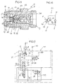
- Fig. 1 shows a Einschraubschraubung E, for example, at least in the outer dimensions according to regulations ISO 3691 or DIN 3852, comprising a block 1, a line or a hose 2 and a screw-3, which hermetically connects the block 1 with the line or hose 2 ( ERMETO principle).
- the screw-3 is for example made of steel and has a screw handle 4 in the form of a hexagon and on both sides of the screw 4 external thread sections 5, 7.
- the screw-3 has a hose or line-side end 9 and a block-side end 10, between which a longitudinal passage 14 extends.
- a seal 8 for example a soft metal seal, is provided, with which in a threaded bore 32 of the block 1 (FIG. Fig.
- screwed screw 3 seals on the outside or a sealing surface of the block 1.
- a union nut 36 and a cutting ring 35 (FIG. Fig. 3 ) is at the end 9 of the screw 3, a conical mouth 6 is formed.
- the screw-in body 3 of the screw-in fitting E in Fig. 1 is structurally for an actively controllable valve function F1 ( Fig. 2 ), and is characterized in particular by the fact that a control channel 11 is formed in the screw-in body 3, which extends from an opening 12 on the outer circumference to an opening 13 in the longitudinal passage 14.
- a control channel 11 is formed in the screw-in body 3, which extends from an opening 12 on the outer circumference to an opening 13 in the longitudinal passage 14.
- integrally formed valve seat 15 a conical valve seat with a sealing edge
- is formed which in the embodiment in Fig. 1 is positioned at the block-side end 10 and within the longitudinal extension of the screw-3.
- a valve element 16 which can be displaced in a sealed manner in a guide section 21 of the longitudinal passage 14, can cooperate with the valve seat 15, which valve element is designed as a pot piston in the embodiment shown and is arranged in the guide section 21 with a large-diameter sealing region 22.
- Adjoining the sealing region 22 is a pot piston end 23 reduced in diameter, on which a conical seat surface 24 (for cooperation with the valve seat 15 in seat valve construction) is integrally formed.
- the seat surface 24 is extended by an immersion extension 25, the diameter of which slightly decreases in the direction of insertion into the opening of the valve seat 15 in order to vary the cross-sectional area which is opened during the stroke of the valve element 16, depending on the stroke and thus to be able to regulate the flow rate.
- valve closing spring 17 which is supported in the screw-3 (not shown).
- the control channel 11 has its inner mouth 13 in an annular chamber 27, in which a control piston 28, z.
- a control piston 28, z. an annular piston, is sealingly displaceable, which rests with its outer periphery on the inner wall of the annular chamber 27 and with its inner circumference on a hollow guide insert 30.
- At least one throttle passage 31 extends through the guide insert 30 into the annular chamber 27th
- the screw-in body 3 has an additional sealing area 18 on the block-side end 10.
- this additional sealing region 18 is formed by an O-ring or a soft metal ring 20 and a support ring 19, which is supported on a shoulder of the screw-3.
- the additional sealing area 18 could also be formed by a sealing cutting edge on the block-side end 10, or by a continuation of the external thread 7 or a separate sealing thread portion (not shown) to the block-side end 10.
- the additional sealing area 18 isolated the block-side end 10 of the longitudinal passage 14 on a mating surface 33 in the block 1 (FIG. Fig. 3 ) from the mouth 12 of the control channel 11 is largely or completely sealed.
- the into the screwed connection E of Fig. 1 integrated, actively controllable valve function F1 is the optional blocking of a check valve (symbol in Fig. 2 ) in the blocking position, which is also held by the pending at the end 9 pressure on the valve element 16 in the (not shown) blocking position, wherein the control channel 11 can be shut off. Also, the valve closing spring 17 acts in the closing direction.
- the control channel 11 is connected in block 1 with a control channel 34, which leads to a control component, not shown, which either shuts off the control channel 11 and 34 or releases or pressurized with control pressure.
- the block-side end 10 of the longitudinal passage 14 leads to a control valve, while at the end 9 a hydraulic motor (not shown) is connected, for example correspondingly Fig. 7 ,
- a hydraulic motor (not shown) is connected, for example correspondingly Fig. 7 .
- this pressure is held in the blocking position of the check valve. It acts in the blocking position, although on the annular surface between the large sealing diameter 22 and the seat diameter, a force component in the opening direction. However, this can not cancel the blocking position. Unlocking is possible if the block-side end 10, a certain pressure is built up. However, the unlocking can be blocked via the control channel 11 with control pressure.
- Control valve 11 For actively controlling blocking of the unlocking or in the in Fig. 1
- Control valve 11 is subjected to control pressure, so that the pressure in the annular space 27 increases, since the cross section of the throttle passages 31 is smaller than the cross section of the control channels 11.
- the actuating force of the actuating piston 18 in the closing direction increases and acts on the valve element 16, wherein the pressure force in the opening direction, the valve element 16 on the annular surface between the sealing diameter 22 and the valve seat 15 is overcome. If the control channel 11 again actively controlled or shut off, the check valve is unlocked again.
- the immersion extension 25 is formed, which varies the passage cross-section through the valve seat 15 depending on the stroke, for example, to achieve a ramp function when closing or opening the check valve.
- valve function that of a check valve or load-holding valve, which can be selectively and actively controlled by Steuertikbeetzung in the control channel 11 with the actuator piston 18 in the locked position and / or preserved in this and lockable. Only when the pressure relief of the control channel 11, the check valve can be opened by pressure from the end 10, as soon as the pressure at the end 10 by a predetermined difference is higher than the pressure at the end of the 9th
- the additional active controllable valve function F3 of a load-holding valve with pressure relief in the reverse direction which can be opened by pressure at the end 10, and actively controlled by control pressure in the control channel 11 is opened and / or kept open.
- the control channel 11 leads here to the block-side end of the longitudinal passage 14 associated annular space 27 left of the valve seat 15 with the inside and outside sealed slidably guided adjusting piston 28 which serves on a rear side 55 for generating an opening force.
- an insert 58 is included as an abutment for a closing spring 17 of the valve element 16.
- the immersion extension 25 is followed by a plurality of circumferentially distributed legs 43, between which quantity control slots 40 can be defined.
- the legs 43 also interact with the actuating piston 28.
- 25 cross passages 38 are optionally provided in the immersion extension.
- the quantity control slots 40 and / or the transverse passages 38 interact with the seat edge of the valve seat 15 in an aperture-like manner in order to be able to carry out a quantity control or to vary the cross-section during the stroke of the valve element 16 in a stroke-dependent manner.
- a pressure relief valve with a closing member 46, a seat with a throttle passage 44, and a closing spring 59 is included in a chamber 41 in the valve element 16.
- the closing spring 59 is supported on an insert part 42 with a passage to the end 10.
- a hydraulic motor At the block-side end 10 of the longitudinal passage 14, for example via a channel 37 (FIG. Fig. 3 ) connected to a control valve, not shown, or a pressure source, while at the opposite end 9 of the longitudinal passage 14, a hydraulic motor can be connected.
- the load of the hydraulic motor is kept free of leaks. If the load pressure exceeds a certain value, the pressure relief valve automatically opens in the blocking position of the load-holding valve in order to limit the pressure via the throttle channel 44. If sufficient pressure is built up on the block-side end 10 of the longitudinal passage 14 via the control valve, the load-holding valve opens against the closing spring 17 to allow flow through the valve seat 15 and the flow passages 26 to the other end 9 of the longitudinal passage 14 and to the hydraulic motor.
- the load-holding valve can be actively unlocked either by pressurizing the control channel 11 and keep open. It then acts the control pressure in the annular space 27 on the annular surface of the actuating piston 28 in the opening direction of the valve element 16, which is displaced over the legs 43. Then pressure fluid from the hydraulic motor can flow through the valve seat 15.
- This active unlocking can be done completely or by the control pressure in the control channel 11 being sensitively varied, so that with the quantity control device only a certain amount flows between the valve element 16 and the valve seat 15.
- the load holding valve with control pressure in the control channel 11 can be kept open until the control pressure is relieved.
- Fig. 7 shows as a block diagram the integration of the screwed E of Fig. 1 and 2 with the valve function F1 of a blocked by pressurization of the control channel 11 in the blocking position check valve into a stroke control module M z.
- the hydraulic motor is, for example, a unilaterally acted upon a load L lifting cylinder Z, which is connected via the line or the hose 2 by means of the Einschraubverschraubung E to the block 1.
- the (one-piece or multi-part) block 1 are a directional control valve 51, a solenoid valve 48 with a black / white switching magnet 49, possibly a drain-pressure compensator 54, a pressure line 52, a return line 53 and also in Fig.
- control channel 34 possibly provided with a control pressure port 60 which connects the control channel 11 of the screwed E with the solenoid switching valve 48.
- the solenoid switching valve 48 is connected either directly to the return line 53, or, as shown, via a line 47 which is shut off in the neutral position O of the directional control valve 51 shown, however, in each control position a or b of the directional control valve 51 via a flow path 56 with the return line 53 and the drain pressure compensator 54 is connected.
- the solenoid 49 of the magnetic switching valve 48 is electrically connected to a seat occupancy switch and / or emergency stop switch and / or operation switch 50, in such a way that the magnet 49 is energized upon actuation of the seat occupancy switch, when not actuated emergency stop switch and actuated operation switch 50 and the solenoid switching valve 48 is in the passage position.
- the magnetic switching valve 48 assumes the shut-off position shown under spring force when the emergency stop switch is actuated and / or the seat occupancy switch does not report occupancy, and / or the operating switch is not turned on.
- the control channel 11 is depressurized only when the directional control valve 51 is adjusted in one of the control positions a, b.
- control pressure is in the control channel 11, as long as the directional control valve 51 is in the shown shut-off neutral position O.
- the safety function provided by the screwed connection E in Fig. 7 is achieved, is that an unintentional adjustment of the lifting cylinder Z is neither against the load L nor under the load L avoided when in the absence of the forklift driver with the emergency stop switch or switch off the operating switch 50, the directional control valve 51 z. B. operated by mistake and there is still pressure in the system.
- the control pressure is maintained in the control channel 11 because the solenoid switching valve 48 is in the blocking position. Under the load pressure from the lifting cylinder Z and / or by control pressure from the port 60, the valve element 16 is blocked in the blocking position.
Landscapes
- Engineering & Computer Science (AREA)
- General Engineering & Computer Science (AREA)
- Mechanical Engineering (AREA)
- Physics & Mathematics (AREA)
- Fluid Mechanics (AREA)
- Lift Valve (AREA)
- Forklifts And Lifting Vehicles (AREA)
Claims (8)
- Raccord à visser (E) avec fonction de soupape entre un bloc (1) et un tuyau flexible ou une conduite (2), notamment pour l'hydraulique à haute pression,
le raccord à visser (E) comportant un corps fileté (3) aux dimensions extérieures très largement standardisées ou normalisées avec des tronçons filetés (5, 7) aux deux extrémités, une prise de vissage (4) située entre les deux ainsi qu'un passage longitudinal (14)
et le corps fileté (3) étant modifié pour la fonction de soupape au moins avec un siège de soupape (15) dans le passage longitudinal (14) et avec un élément de soupape (16) qui est commandé par ressort et mobile dans le sens de la longueur par rapport au siège de soupape (15) et qui est un piston en cloche qui est guidé mobile sur la circonférence extérieure avec un diamètre d'étanchéité (22) supérieur au diamètre intérieur du siège de soupape (15) dans un tronçon de guidage (21) du passage longitudinal (14) et qui comporte une extrémité de piston en cloche (23) avec un diamètre extérieur réduit par rapport au diamètre d'étanchéité (22) et avec une surface d'assise conique (24) ainsi que des passages d'écoulement (26) de l'extrémité arrière de piston en cloche à l'extrémité de piston en cloche (23),
le corps fileté (3) étant conçu pour une fonction de soupape (F1, F2, F3) qui peut être commandée de manière active et optionnelle et qui a au moins un canal de commande (11) menant de la circonférence extérieure du corps fileté (3) au passage longitudinal (14),
caractérisé en ce qu'il est prévu à l'extrémité de piston en cloche (23) et de manière adjacente à la surface d'assise (24), pour la régulation du débit par le siège de soupape (15), un prolongement plongeant (25) qui plonge dans le siège de soupape (15) lorsque la surface d'assise (24) est posée et dont le diamètre extérieur correspond sensiblement au diamètre intérieur du siège de soupape (15). - Raccord à visser selon la revendication 1, caractérisé en ce que le prolongement plongeant (25) se rétrécit en coupe axiale dans la direction de la plongée.
- Raccord à visser selon la revendication 1, caractérisé en ce que des branches (39), prenant par le siège de soupape (15) et réparties sur toute la circonférence, font saillie sur le prolongement plongeant (25), branches entre lesquelles sont définies des fentes de commande de débit (40), et en ce que des passages de commande de débit (38) sont prévus dans le prolongement plongeant (25).
- Raccord à visser selon la revendication 1, caractérisé en ce qu'il est prévu dans le prolongement plongeant (25) de l'élément de soupape (16) une chambre (41), placée à l'intérieur, qui contient une soupape limitant la pression et qui communique d'un côté avec l'extrémité côté bloc (10) du passage longitudinal (14) et de l'autre côté par l'intermédiaire d'un passage à étranglement (44) avec l'extrémité arrière de l'élément de soupape (16).
- Raccord à visser selon la revendication 1, caractérisé en ce que la fonction de soupape (F1, F2, F3), qui peut être commandée de manière active et optionnelle, du raccord à visser (E) est une fonction de soupape de non-retour pouvant être bloquée avec une application de pression de commande du canal de commande (11) ou un déblocage, dosé avec une application de pression de commande du canal de commande (11), d'une fonction de soupape de non-retour ou d'une fonction de soupape de maintien de charge avec limitation de pression dans le sens du blocage.
- Raccord à visser selon la revendication 1, caractérisé en ce que le canal de commande (11) débouche dans le passage longitudinal (14), du côté du bloc ou du côté opposé au côté du bloc, dans un espace annulaire (27) dans lequel est agencé, de manière mobile et étanche, un piston de réglage d'élément de soupape (28) dont la construction est séparée de l'élément de soupape (16) et qui définit dans l'espace annulaire (27) une surface annulaire (55) pouvant être soumise à la pression de commande dans le canal de commande (11) dans le sens soit de la fermeture soit de l'ouverture de l'élément de soupape (16).
- Raccord à visser selon la revendication 6, caractérisé en ce que l'espace annulaire (27) est relié au passage longitudinal (14) par un passage à étranglement (31).
- Raccord à visser selon au moins l'une des revendications précédentes, caractérisé en ce que le raccord à visser (E) avec la fonction de soupape (F1) de la soupape de non-retour pouvant être débloquée de manière active et optionnelle par une application de pression de commande est agencé dans un bloc de soupape (1) d'un module de commande de levage (M) d'un chariot élévateur à fourche, en ce que, sur celui des côtés du corps fileté (3) qui est éloigné du siège de soupape (15), la conduite (2) est raccordée à un cylindre de levage (Z) et, sur celui des côtés du corps fileté (3) qui est proche du siège de soupape (15), une soupape de commande de sens ou une source de pression (51) est raccordée et en ce que le canal de commande (11) pouvant être soumis à la pression de commande est raccordé, par l'intermédiaire d'une soupape à commutation magnétique (48, 49) reliée à un interrupteur d'urgence et/ou à un interrupteur d'occupation de siège et/ou à un interrupteur de fonctionnement (50) du chariot élévateur à fourche, à une conduite de retour (53) par l'intermédiaire d'un trajet d'écoulement (56) de la soupape de commande de sens (51) .
Priority Applications (2)
| Application Number | Priority Date | Filing Date | Title |
|---|---|---|---|
| DE200850003019 DE502008003019D1 (de) | 2008-08-19 | 2008-08-19 | Einschraubverschraubung |
| EP20080014728 EP2157321B1 (fr) | 2008-08-19 | 2008-08-19 | Raccord à visser |
Applications Claiming Priority (1)
| Application Number | Priority Date | Filing Date | Title |
|---|---|---|---|
| EP20080014728 EP2157321B1 (fr) | 2008-08-19 | 2008-08-19 | Raccord à visser |
Publications (2)
| Publication Number | Publication Date |
|---|---|
| EP2157321A1 EP2157321A1 (fr) | 2010-02-24 |
| EP2157321B1 true EP2157321B1 (fr) | 2011-03-30 |
Family
ID=40259073
Family Applications (1)
| Application Number | Title | Priority Date | Filing Date |
|---|---|---|---|
| EP20080014728 Not-in-force EP2157321B1 (fr) | 2008-08-19 | 2008-08-19 | Raccord à visser |
Country Status (2)
| Country | Link |
|---|---|
| EP (1) | EP2157321B1 (fr) |
| DE (1) | DE502008003019D1 (fr) |
Families Citing this family (5)
| Publication number | Priority date | Publication date | Assignee | Title |
|---|---|---|---|---|
| EP2466155B1 (fr) | 2010-12-15 | 2013-02-13 | HAWE Hydraulik SE | Soupape à siège anti-retour déverrouillable de manière hydraulique |
| CN106051346A (zh) * | 2015-05-22 | 2016-10-26 | 中山市雅西环保科技有限公司 | 一种连接件 |
| CN108953713B (zh) * | 2018-08-22 | 2021-09-28 | 宁波威森搏乐机械制造有限公司 | 流量型平衡阀 |
| CN116025746A (zh) * | 2021-12-16 | 2023-04-28 | 中船重工重庆液压机电有限公司 | 一种直通式安全阀及伺服油缸 |
| CN118564509B (zh) * | 2024-04-29 | 2026-01-06 | 建湖县威力液压机械制造有限公司 | 一种具有密封结构的船用舵机液压阀组和密封方法 |
Family Cites Families (9)
| Publication number | Priority date | Publication date | Assignee | Title |
|---|---|---|---|---|
| DE2500552C2 (de) | 1975-01-08 | 1977-02-24 | Heilmeier & Weinlein | Sicherungsventil fuer rohr- bzw. schlauchbrueche |
| US4174824A (en) | 1977-05-13 | 1979-11-20 | Eaton Corporation | Pressure operated pilot control shut-off valve |
| DE2820811A1 (de) * | 1978-05-12 | 1979-11-15 | Gok Gmbh & Co Kg | Schlauch-und rohrbruchsicherung |
| DE3722126A1 (de) | 1986-07-23 | 1988-02-04 | Dana Corp | Steuerventil |
| SE456766B (sv) * | 1987-06-17 | 1988-10-31 | Hiab Foco Ab | Slang-eller ledningsbrottsventil |
| DE4034667A1 (de) * | 1990-10-31 | 1992-05-07 | Rudolf Pickel | Hydraulische steuervorrichtung mit baukastenartig aneinanderbaubaren bauteilen |
| AT411923B (de) | 2000-08-23 | 2004-07-26 | Weber Gisela | Hydraulikventil |
| DE20119058U1 (de) | 2001-11-23 | 2003-04-03 | Voss Fluid GmbH + Co. KG, 51688 Wipperfürth | Rohrbruchventil |
| DE20311848U1 (de) | 2003-07-31 | 2004-12-09 | Hawe Hydraulik Gmbh & Co. Kg | Schlauchbruchventil |
-
2008
- 2008-08-19 EP EP20080014728 patent/EP2157321B1/fr not_active Not-in-force
- 2008-08-19 DE DE200850003019 patent/DE502008003019D1/de active Active
Also Published As
| Publication number | Publication date |
|---|---|
| EP2157321A1 (fr) | 2010-02-24 |
| DE502008003019D1 (de) | 2011-05-12 |
Similar Documents
| Publication | Publication Date | Title |
|---|---|---|
| EP2107257B1 (fr) | Vérin fluidique | |
| EP2294331B1 (fr) | Dispositif de vanne hydraulique | |
| DE19813909A1 (de) | Hydraulisch aufsteuerbares Rückschlagventil für die Ausbauhydraulik in Bergbau-Untertagebetrieben | |
| DE4212550C2 (de) | Ventilanordnung mit einem Wegeventil | |
| DE19744337A1 (de) | Vorgesteuertes Druckbegrenzungsventil | |
| EP3308031B1 (fr) | Soupape de régulation de pression | |
| EP2157321B1 (fr) | Raccord à visser | |
| DE1963114A1 (de) | Vorrichtung zur Zufuehrung von Druckfluessigkeit | |
| EP1851098B1 (fr) | Cylindre de frein a accumulateur a ressort et de service combine avec dispositif de respiration | |
| EP0902194B1 (fr) | Soupape à maintien de charge | |
| WO2022106168A1 (fr) | Soupape | |
| DE2945911C2 (fr) | ||
| DE4112065A1 (de) | Vorgesteuertes druckabschaltventil mit einstellbarer schaltdruckdifferenz | |
| EP4254126B1 (fr) | Soupape à tiroir proportionnel doté d'une soupape de limitation de pression et système hydraulique | |
| DE102021109704B4 (de) | Entsperrbares Rückschlagventil | |
| EP1694958B1 (fr) | Soupape de limitation de pression pour des dispositifs d'injection de carburant | |
| DE102007051029B4 (de) | Ventileinrichtung | |
| EP2639104B1 (fr) | Commande hydraulique d'un vérin de basculement facilement actionnable | |
| DE102009053918A1 (de) | Proportional verstellbare Druckbegrenzungs- und Nachsaugventilanordnung | |
| DE2833971A1 (de) | Leitungsbruchsicherungs-vorrichtung | |
| DE19625348A1 (de) | Anordnung zur Ansteuerung eines hydraulisch betätigbaren Hauptventils | |
| EP1853826A2 (fr) | Soupape hydraulique | |
| EP4733603A1 (fr) | Clapet anti-retour | |
| DE102012220865A1 (de) | Stetig verstellbares Ventil und hydraulische Steueranordnung mit einem derartigen Ventil | |
| EP2484945A1 (fr) | Distributeur hydraulique doté d'un dispositif d'arrêt |
Legal Events
| Date | Code | Title | Description |
|---|---|---|---|
| PUAI | Public reference made under article 153(3) epc to a published international application that has entered the european phase |
Free format text: ORIGINAL CODE: 0009012 |
|
| 17P | Request for examination filed |
Effective date: 20090331 |
|
| AK | Designated contracting states |
Kind code of ref document: A1 Designated state(s): AT BE BG CH CY CZ DE DK EE ES FI FR GB GR HR HU IE IS IT LI LT LU LV MC MT NL NO PL PT RO SE SI SK TR |
|
| AX | Request for extension of the european patent |
Extension state: AL BA MK RS |
|
| GRAP | Despatch of communication of intention to grant a patent |
Free format text: ORIGINAL CODE: EPIDOSNIGR1 |
|
| GRAS | Grant fee paid |
Free format text: ORIGINAL CODE: EPIDOSNIGR3 |
|
| AKX | Designation fees paid |
Designated state(s): DE FR IT |
|
| GRAA | (expected) grant |
Free format text: ORIGINAL CODE: 0009210 |
|
| AK | Designated contracting states |
Kind code of ref document: B1 Designated state(s): DE FR IT |
|
| REF | Corresponds to: |
Ref document number: 502008003019 Country of ref document: DE Date of ref document: 20110512 Kind code of ref document: P |
|
| REG | Reference to a national code |
Ref country code: DE Ref legal event code: R096 Ref document number: 502008003019 Country of ref document: DE Effective date: 20110512 |
|
| PLBE | No opposition filed within time limit |
Free format text: ORIGINAL CODE: 0009261 |
|
| STAA | Information on the status of an ep patent application or granted ep patent |
Free format text: STATUS: NO OPPOSITION FILED WITHIN TIME LIMIT |
|
| 26N | No opposition filed |
Effective date: 20120102 |
|
| REG | Reference to a national code |
Ref country code: DE Ref legal event code: R097 Ref document number: 502008003019 Country of ref document: DE Effective date: 20120102 |
|
| PGFP | Annual fee paid to national office [announced via postgrant information from national office to epo] |
Ref country code: FR Payment date: 20140822 Year of fee payment: 7 |
|
| REG | Reference to a national code |
Ref country code: FR Ref legal event code: ST Effective date: 20160429 |
|
| PG25 | Lapsed in a contracting state [announced via postgrant information from national office to epo] |
Ref country code: FR Free format text: LAPSE BECAUSE OF NON-PAYMENT OF DUE FEES Effective date: 20150831 |
|
| REG | Reference to a national code |
Ref country code: DE Ref legal event code: R082 Ref document number: 502008003019 Country of ref document: DE Representative=s name: GROSSE, SCHUMACHER, KNAUER, VON HIRSCHHAUSEN, DE |
|
| PGFP | Annual fee paid to national office [announced via postgrant information from national office to epo] |
Ref country code: IT Payment date: 20160831 Year of fee payment: 9 |
|
| REG | Reference to a national code |
Ref country code: DE Ref legal event code: R082 Ref document number: 502008003019 Country of ref document: DE Representative=s name: GROSSE, SCHUMACHER, KNAUER, VON HIRSCHHAUSEN, DE Ref country code: DE Ref legal event code: R081 Ref document number: 502008003019 Country of ref document: DE Owner name: HAWE HYDRAULIK SE, DE Free format text: FORMER OWNER: HAWE HYDRAULIK SE, 81673 MUENCHEN, DE |
|
| PG25 | Lapsed in a contracting state [announced via postgrant information from national office to epo] |
Ref country code: IT Free format text: LAPSE BECAUSE OF NON-PAYMENT OF DUE FEES Effective date: 20170819 |
|
| PGFP | Annual fee paid to national office [announced via postgrant information from national office to epo] |
Ref country code: DE Payment date: 20190828 Year of fee payment: 12 |
|
| REG | Reference to a national code |
Ref country code: DE Ref legal event code: R119 Ref document number: 502008003019 Country of ref document: DE |
|
| PG25 | Lapsed in a contracting state [announced via postgrant information from national office to epo] |
Ref country code: DE Free format text: LAPSE BECAUSE OF NON-PAYMENT OF DUE FEES Effective date: 20210302 |
|
| P01 | Opt-out of the competence of the unified patent court (upc) registered |
Effective date: 20230523 |