EP2157353A1 - Aufbewahrungsbehälter für flüssiges Chlorsilan und Schließdeckel dafür - Google Patents
Aufbewahrungsbehälter für flüssiges Chlorsilan und Schließdeckel dafür Download PDFInfo
- Publication number
- EP2157353A1 EP2157353A1 EP20090167580 EP09167580A EP2157353A1 EP 2157353 A1 EP2157353 A1 EP 2157353A1 EP 20090167580 EP20090167580 EP 20090167580 EP 09167580 A EP09167580 A EP 09167580A EP 2157353 A1 EP2157353 A1 EP 2157353A1
- Authority
- EP
- European Patent Office
- Prior art keywords
- valve
- closing lid
- space
- storage container
- pipe
- Prior art date
- Legal status (The legal status is an assumption and is not a legal conclusion. Google has not performed a legal analysis and makes no representation as to the accuracy of the status listed.)
- Granted
Links
Images

Classifications
-
- F—MECHANICAL ENGINEERING; LIGHTING; HEATING; WEAPONS; BLASTING
- F16—ENGINEERING ELEMENTS AND UNITS; GENERAL MEASURES FOR PRODUCING AND MAINTAINING EFFECTIVE FUNCTIONING OF MACHINES OR INSTALLATIONS; THERMAL INSULATION IN GENERAL
- F16K—VALVES; TAPS; COCKS; ACTUATING-FLOATS; DEVICES FOR VENTING OR AERATING
- F16K5/00—Plug valves; Taps or cocks comprising only cut-off apparatus having at least one of the sealing faces shaped as a more or less complete surface of a solid of revolution, the opening and closing movement being predominantly rotary
- F16K5/06—Plug valves; Taps or cocks comprising only cut-off apparatus having at least one of the sealing faces shaped as a more or less complete surface of a solid of revolution, the opening and closing movement being predominantly rotary with plugs having spherical surfaces; Packings therefor
- F16K5/0626—Easy mounting or dismounting means
- F16K5/0631—Easy mounting or dismounting means between two flanges
-
- F—MECHANICAL ENGINEERING; LIGHTING; HEATING; WEAPONS; BLASTING
- F17—STORING OR DISTRIBUTING GASES OR LIQUIDS
- F17C—VESSELS FOR CONTAINING OR STORING COMPRESSED, LIQUEFIED OR SOLIDIFIED GASES; FIXED-CAPACITY GAS-HOLDERS; FILLING VESSELS WITH, OR DISCHARGING FROM VESSELS, COMPRESSED, LIQUEFIED, OR SOLIDIFIED GASES
- F17C13/00—Details of vessels or of the filling or discharging of vessels
- F17C13/04—Arrangement or mounting of valves
-
- F—MECHANICAL ENGINEERING; LIGHTING; HEATING; WEAPONS; BLASTING
- F16—ENGINEERING ELEMENTS AND UNITS; GENERAL MEASURES FOR PRODUCING AND MAINTAINING EFFECTIVE FUNCTIONING OF MACHINES OR INSTALLATIONS; THERMAL INSULATION IN GENERAL
- F16K—VALVES; TAPS; COCKS; ACTUATING-FLOATS; DEVICES FOR VENTING OR AERATING
- F16K27/00—Construction of housing; Use of materials therefor
- F16K27/06—Construction of housing; Use of materials therefor of taps or cocks
- F16K27/067—Construction of housing; Use of materials therefor of taps or cocks with spherical plugs
-
- F—MECHANICAL ENGINEERING; LIGHTING; HEATING; WEAPONS; BLASTING
- F17—STORING OR DISTRIBUTING GASES OR LIQUIDS
- F17C—VESSELS FOR CONTAINING OR STORING COMPRESSED, LIQUEFIED OR SOLIDIFIED GASES; FIXED-CAPACITY GAS-HOLDERS; FILLING VESSELS WITH, OR DISCHARGING FROM VESSELS, COMPRESSED, LIQUEFIED, OR SOLIDIFIED GASES
- F17C13/00—Details of vessels or of the filling or discharging of vessels
- F17C13/06—Closures, e.g. cap, breakable member
-
- Y—GENERAL TAGGING OF NEW TECHNOLOGICAL DEVELOPMENTS; GENERAL TAGGING OF CROSS-SECTIONAL TECHNOLOGIES SPANNING OVER SEVERAL SECTIONS OF THE IPC; TECHNICAL SUBJECTS COVERED BY FORMER USPC CROSS-REFERENCE ART COLLECTIONS [XRACs] AND DIGESTS
- Y10—TECHNICAL SUBJECTS COVERED BY FORMER USPC
- Y10T—TECHNICAL SUBJECTS COVERED BY FORMER US CLASSIFICATION
- Y10T137/00—Fluid handling
- Y10T137/4238—With cleaner, lubrication added to fluid or liquid sealing at valve interface
-
- Y—GENERAL TAGGING OF NEW TECHNOLOGICAL DEVELOPMENTS; GENERAL TAGGING OF CROSS-SECTIONAL TECHNOLOGIES SPANNING OVER SEVERAL SECTIONS OF THE IPC; TECHNICAL SUBJECTS COVERED BY FORMER USPC CROSS-REFERENCE ART COLLECTIONS [XRACs] AND DIGESTS
- Y10—TECHNICAL SUBJECTS COVERED BY FORMER USPC
- Y10T—TECHNICAL SUBJECTS COVERED BY FORMER US CLASSIFICATION
- Y10T137/00—Fluid handling
- Y10T137/5109—Convertible
-
- Y—GENERAL TAGGING OF NEW TECHNOLOGICAL DEVELOPMENTS; GENERAL TAGGING OF CROSS-SECTIONAL TECHNOLOGIES SPANNING OVER SEVERAL SECTIONS OF THE IPC; TECHNICAL SUBJECTS COVERED BY FORMER USPC CROSS-REFERENCE ART COLLECTIONS [XRACs] AND DIGESTS
- Y10—TECHNICAL SUBJECTS COVERED BY FORMER USPC
- Y10T—TECHNICAL SUBJECTS COVERED BY FORMER US CLASSIFICATION
- Y10T137/00—Fluid handling
- Y10T137/5109—Convertible
- Y10T137/5283—Units interchangeable between alternate locations
Definitions
- the present invention relates to a storage container for a liquid chlorosilane, and a closing lid for the storage container.
- Chlorosilanes such as trichlorosilane or silicon tetrachloride, are used for semiconductors, such as polycrystalline silicon and epitaxial films on silicon wafers, and for the raw materials of optical fibers, and the like.
- chlorosilanes are filled into containers or cylinders in manufacturing factories, and are carried to and used in manufacturing factories of semiconductors, optical fibers, or the like. When the chlorosilanes react with moisture in the air or the like, corrosive gas and silica are generated.
- chlorosilanes stored the container must be prevented from contacting air or moisture.
- closing structures as described in Japanese Patent Unexamined Publication Nos. 5-231598 and 2008-116044 are conventionally adopted.
- a cap which airtightly seals the mouthpiece is provided, and an adsorbent which adsorbs moisture and oxygen, or an adsorbent which adsorbs silane gas is provided in this cap.
- Japanese Patent Unexamined Publication No. 5-231598 in order to prevent silane gas leaked when a valve is loosened from igniting spontaneously in air, contaminating a mouthpiece, or corroding the mouthpiece or a gas supply system, a cap which airtightly seals the mouthpiece is provided, and an adsorbent which adsorbs moisture and oxygen, or an adsorbent which adsorbs silane gas is provided in this cap.
- 5-231598 describes that, since the atmosphere in the mouthpiece and the cap is replaced with an inert gas composed mainly of nitrogen gas or the like by this adsorbent, corrosion can be suppressed even if the silane gas leaks out.
- a leak control device in which a leaked reactive gas can be collected by providing a containment enclosure so as to enclose a fluid flow part connected to an outlet opening of a container is described in Japanese Patent Unexamined Publication No. 2008-116044 .
- Japanese Patent Unexamined Publication Nos. 5-231598 and 2008-116044 which have the prevention of gas leaks as their object cannot be applied to storage containers of liquid chlorosilanes.
- absorption cannot be made by an adsorbent when liquid chlorosilane is leaked.
- an apparatus of Japanese Patent Unexamined Publication No. 2008-116044 is an effective means in regard to leaks in a pipe connecting portion, but is not an effective means when there are leaks caused by deterioration of sealing performance of a valve.
- the chlorosilanes contact air, they react with the air, thereby generating rust on a valve or silica adhere to the valve which obstructs the operation of the valve.
- the end of a valve is sealed by a closing lid, the air including moisture exists in the sealed space formed between the valve and the closing lid. Therefore, when the leak of the chlorosilanes is caused by deterioration of sealing performance of the valve, the inside of the valve is corroded by the reaction with the moisture.
- the present invention was made in view of such a situation, and the object thereof is to provide a storage container for a liquid chlorosilane and a closing lid for the storage container which can maintain the soundness of a valve with simple structure and reliably prevent the generation of corrosive gas caused by the leaking of its contents.
- the storage container for a liquid chlorosilane of the present invention for achieving the above object is a storage container for a liquid chlorosilane comprising, a tank which stores the liquid chlorosilane, a valve which is connected to the tank and to which an external pipe can be connected detachably, and a closing lid which seals the valve when the external pipe is detached from the valve.
- the valve comprises a housing and a valve body provided in the housing, the housing has a connecting flange having a connecting surface to be connected detachably to the external pipe.
- the closing lid has a lid body having a sealing surface contacting the connecting surface of the connecting flange, a supply pipe which supplies an inert gas to a space between the closing lid and the valve body in the housing, a supply valve which opens or closes the supply pipe, a discharge pipe which discharges a gas in the space, and a discharge valve which opens or closes the discharge pipe.
- a space formed between the valve body of the valve and the closing lid can be filled with an inert gas which does not react with a liquid chlorosilane, generation of corrosive gas or silica can be prevented. Further, since this space can be given positive pressure relative to the inside of the storage container, the sealing performance of the valve can be enhanced and leaks from the valve can be prevented.
- the closing lid for a liquid chlorosilane storage container of the present invention is a closing lid for a liquid chlorosilane storage container connected detachably to a connecting flange of a valve fixed to a tank which stores the liquid chlorosilane.
- the closing lid comprises a lid body having a sealing surface contacting a connecting surface of the connecting flange, a supply pipe which supplies an inert gas to a space between the closing lid and a valve body of the valve, a supply valve which opens or closes the supply pipe, a discharge pipe which discharges a gas in the space, and a discharge valve which opens or closes the discharge pipe.
- the closing lid is fixed to the connecting flange to seal the space.
- the storage container for a liquid chlorosilane and the closing lid for the storage container of the present invention generation of corrosive gas or silica is suppressed.
- the deterioration of the sealing performance of the valve or leaks of a liquid chlorosilane, which is caused by the corrosion of the surrounding members of the valve, can be prevented, and the risk when the closing lid is detached can also be reduced.
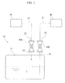
- FIG. 1 A schematic diagram of a storage container 10 for a liquid chlorosilane L of the present invention, an inert gas supply tool 20 which supplies inert gas (for example, argon gas) to the storage container 10, and a container 30 which stores the liquid chlorosilane L extracted from the storage container 10 is shown in FIG. 1 .
- inert gas for example, argon gas
- the storage container 10 includes a tank 11 and two valves 40A and 40B.
- Two valves 40A and 40B have a duct which allows the inside and outside of the tank 11 to be linked with each other, and open and close this duct.
- the valves 40A and 40B are so-called ball valves.
- One valve 40A is for the supplying of inert gas to the tank 11 and when the liquid chlorosilane L is extracted, an attaching flange 22 is connected to a connecting flange 42 (shown in Fig. 2 .) of the valve.
- the attaching flange 22 is provided in a external pipe 21 which extends from the inert gas supply tool 20 which supplies inert gas (for example, argon gas).
- the other valve 40B is for extracting the liquid chlorosilane L from the tank 11, and an attaching flange 32, included in a external pipe 31 which extends from an external container 30, is connected to a connecting flange 42 of the valve.
- inert gas is injected into the tank 11 from the inert gas supply tool 20 via the external pipe 21 and the ball valve 40A, whereby the liquid chlorosilane L is delivered from the tank 11to the container 30 via the ball valve 40B and the external pipe 31. Then, the delivery of the liquid chlorosilane L is stopped by closing each of the ball valves 40A and 40B.
- the ball valve 40 includes a housing 41 which has the spherical valve seat 41a, connecting flanges 42 and 43 which are provided at both ends of the housing 41, a substantially spherical valve body 44 held rotatably at the valve seat 41a so as to open and close a duct 41b, and an operating portion 45 of the valve body 44.
- the ball valve 40 is attached to the tank 11 by fixing one connecting flange 43 to the fixed flange 12 on the side of the tank 11 by bolts 51 and nuts 52.
- any one of the attaching flange 22 of the external pipe 21 which extends from the aforementioned inert gas supply tool 20, the attaching flange 32 of the external pipe 31 which extends from the external container 30, or the closing lid 60 is fixed to the other connecting flange 42 by bolts 51 1 and nuts 52.
- the valve body 44 is formed with a through hole 44a.
- the duct 41b is shut off by disposing the through hole 44a in a direction orthogonal to the duct 41 b of the valve 40, and the duct 41 b is opened by rotating the operating portion 45 to make the through hole 44a coincide with the duct 41 b of the valve 40 as shown by a chain line.
- the closing lid 60 includes a lid body 61 which has a sealing surface 61 a which contacts a connecting surface 42a via a gasket 66, a supply pipe 62 opened to the sealing surface 61a of the lid body 61 and a supply valve 63 provided in the supply pipe 62, and a discharge pipe 64 opened to the sealing surface 61 a of the lid body 61 and a discharge valve 65 provided in the discharge pipe 64.
- a protruding portion 46 is integrally provided at a central portion of an end surface of the connecting flange 42 of the ball valve 40 in the shape of a circular ring plate so as to surround the duct 41b.
- a tip surface of the protruding portion 46 is formed as the connecting surface 42a, and the sealing surface 61a of the lid body 61 in the closing lid 60 is connected to the connecting surface 42a via the gasket 66 made of tetrafluoroethylene or the like.
- the lid body 61 and the connecting flange 42 are fixed together by the bolts 51 and the nuts 52.
- two ring grooves 67 having V-shaped cross-section are formed respectively in the connecting surface 42a of the protruding portion 46 in the connecting flange 42, and in the sealing surface 61a of the lid body 61 so as to face each other via the gasket 66.
- the ring grooves 67 are adapted to make the gasket 66 bite into the corner portions of the ring grooves 67 by the pressure caused by the fastening, thereby securing surface pressure to prevent oozing, and are adapted to be able to secure the prevention of the positional deviation of the gasket 66 between the above surfaces to improve sealing performance to reliably prevent oozing to the outside, when the chlorosilane is oozed out of the sealing surface 61 a of the lid body 61, the connecting surface 42a of the connecting flanges 42 and the surfaces of the gasket 66.
- a space S sealed between the valve body 44 and the lid body 61 is formed in the duct 41b inside the ball valve 40.
- Inert gas such as argon gas
- argon gas can be injected into this space S via the supply pipe 62 and the supply valve 63 of the closing lid 60, and the gas in the space S can be discharged via the discharge pipe 64 and the discharge valve 65. Since this can bring the inside of the space S into an inert atmosphere, a reaction with the moisture in the air accompanying the remaining liquid chlorosilane L in the space S can be prevented. Therefore, generation of corrosive gas and of silica (example: SiHCl 3 +2H 2 O ⁇ SiO 2 +H 2 +3HCl) can be prevented.
- the discharge gas from the space S can be subjected to detoxification processing by connecting a detoxifying tool, such as a scrubber, to the discharge pipe 64.
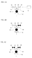
- FIGS. 4A to 4C a blacked state is shown as a sealed state, and an outlined state is shown as an opened state.
- the supply valve 63 and the discharge valve 65 are opened with the ball valve 40 sealed, and inert gas is injected into the space S through the supply pipe 62. Since the discharge valve 65 is opened in the meantime, the gas in the space S is driven out and replaced by inert gas, and inert gas including chlorosilane gas is delivered to a scrubber 70 from the discharge pipe 64. If the inside of the space S is replaced by inert gas, as shown in FIG.
- the discharge valve 65 is sealed while continuing the injection of the inert gas, thereby increasing the pressure in the space S.
- the supply valve 63 is sealed.
- the liquid chlorosilane L is prevented from leaking into the space S through the valve body 44 from the tank 11, and air from the outside is prevented from leaking into the space S via between the valve body and the lid body 61 of the closing lid 60. Accordingly, generation of corrosive gas, silica, etc. is prevented and deterioration of the sealing performance of the ball valve 40 can be prevented.
- the present invention is not limited to the configuration of the above embodiment, but in the detailed configuration, various modifications can be made without departing from the spirit and scope of the present invention.
- the closing lid 60 connected to the valve 40 may be connected to at least the valve 40B on the liquid extraction side.
- corrosion or the like in the valve 40A can also be prevented by connecting the closing lid 60 to the valve 40A on the inert gas supply side.
- inert gas such as argon gas
- nitrogen gas may be used instead of argon gas or the like, and nitrogen is included as an inert gas in the present invention.
- the tank 11 of the storage container 10 is provided with the ball valve 40.
- valve mechanism other than a ball valve may be adopted.
- valve mechanism of the supply valve 63 and the discharge valve 65 is also not particularly limited.
- stainless steel such as SUS304 or SUS316, is used as the material of the tank 11 or the lid body 61. Although the same kind of stainless steel is used as the material of the valve 40 and piping, carbon steel or the like can be used depending on constituent parts.
Landscapes
- Engineering & Computer Science (AREA)
- General Engineering & Computer Science (AREA)
- Mechanical Engineering (AREA)
- Filling Or Discharging Of Gas Storage Vessels (AREA)
- Packging For Living Organisms, Food Or Medicinal Products That Are Sensitive To Environmental Conditiond (AREA)
- Agricultural Chemicals And Associated Chemicals (AREA)
- Sampling And Sample Adjustment (AREA)
- Valve Housings (AREA)
- Organic Low-Molecular-Weight Compounds And Preparation Thereof (AREA)
- Closures For Containers (AREA)
Applications Claiming Priority (1)
| Application Number | Priority Date | Filing Date | Title |
|---|---|---|---|
| JP2008208320 | 2008-08-13 |
Publications (2)
| Publication Number | Publication Date |
|---|---|
| EP2157353A1 true EP2157353A1 (de) | 2010-02-24 |
| EP2157353B1 EP2157353B1 (de) | 2011-04-27 |
Family
ID=41278584
Family Applications (1)
| Application Number | Title | Priority Date | Filing Date |
|---|---|---|---|
| EP20090167580 Active EP2157353B1 (de) | 2008-08-13 | 2009-08-10 | Aufbewahrungsbehälter für flüssiges Chlorsilan und Schließdeckel dafür |
Country Status (7)
| Country | Link |
|---|---|
| US (1) | US8297304B2 (de) |
| EP (1) | EP2157353B1 (de) |
| JP (1) | JP5316302B2 (de) |
| KR (1) | KR101544618B1 (de) |
| CN (1) | CN101649957B (de) |
| AT (1) | ATE507433T1 (de) |
| DE (1) | DE602009001159D1 (de) |
Families Citing this family (9)
| Publication number | Priority date | Publication date | Assignee | Title |
|---|---|---|---|---|
| US8590705B2 (en) * | 2010-06-11 | 2013-11-26 | Air Products And Chemicals, Inc. | Cylinder surface treated container for monochlorosilane |
| GB201109354D0 (en) * | 2011-06-03 | 2011-07-20 | Cordex Instr Ltd | Fuel container |
| JP6450495B1 (ja) * | 2018-08-23 | 2019-01-09 | 六菱ゴム株式会社 | ベント配管閉塞用器具 |
| CN110193223B (zh) * | 2019-06-03 | 2024-06-18 | 南京宏匡硅材料有限公司 | 一种氯硅烷废液的储存装置 |
| GB2588906A (en) * | 2019-11-13 | 2021-05-19 | Edwards Ltd | Gas purged valve |
| TWI766215B (zh) * | 2019-12-05 | 2022-06-01 | 蔡孟學 | 高純度無機化合物二氯矽烷(SiHCl)分裝儲存容器的填充方法 |
| FR3107941B1 (fr) * | 2020-03-09 | 2022-03-11 | Gaztransport Et Technigaz | Bloc modulaire isolant pour cuve étanche et thermiquement isolante |
| US11547846B2 (en) * | 2021-02-23 | 2023-01-10 | Ventriflo, Inc. | Pump-valving assembly for a pulsatile fluid pump |
| CN112944205B (zh) * | 2021-03-12 | 2023-03-14 | 中国恩菲工程技术有限公司 | 氯硅烷充装系统和充装方法 |
Citations (8)
| Publication number | Priority date | Publication date | Assignee | Title |
|---|---|---|---|---|
| US4979643A (en) * | 1985-06-21 | 1990-12-25 | Air Products And Chemicals, Inc. | Chemical refill system |
| JPH05231598A (ja) | 1992-02-18 | 1993-09-07 | Toshiba Corp | ガス充填容器 |
| US5279338A (en) * | 1990-09-28 | 1994-01-18 | Olin Hunt Specialty Products, Inc. | Modular bubbler container automatic refill system |
| EP0719978A2 (de) * | 1994-12-30 | 1996-07-03 | L'air Liquide, Societe Anonyme Pour L'etude Et L'exploitation Des Procedes Georges Claude | Verfahren zum Verteilen von ultrareinen Gasen mit minimierter Korrosion |
| US20020162340A1 (en) * | 2001-05-07 | 2002-11-07 | Guillaume Boucher | Device for closing and connecting to external conduits a reservoir of cryogenic fluid, and reservoir provided with such a device |
| US20020189709A1 (en) * | 1997-07-11 | 2002-12-19 | Noah Craig M. | Bulk chemical delivery system |
| JP2008116044A (ja) | 2006-10-31 | 2008-05-22 | Air Products & Chemicals Inc | 反応性気体用の漏洩抑制装置 |
| JP2008208320A (ja) | 2007-01-29 | 2008-09-11 | Kyocera Corp | 蛍光体とその製造方法および波長変換器ならびに発光装置 |
Family Cites Families (8)
| Publication number | Priority date | Publication date | Assignee | Title |
|---|---|---|---|---|
| US4462568A (en) * | 1982-03-15 | 1984-07-31 | Xomox Corporation | Valve construction and method of making the same |
| DE3544260A1 (de) * | 1985-12-14 | 1987-06-19 | Merck Patent Gmbh | Behaelter fuer aggressive fluessigkeiten |
| US5102010A (en) * | 1988-02-16 | 1992-04-07 | Now Technologies, Inc. | Container and dispensing system for liquid chemicals |
| US5086804A (en) * | 1991-01-23 | 1992-02-11 | Solkatronic Chemicals, Inc. | Emergency security device for head of a leaking gas cylinder |
| JP3805102B2 (ja) * | 1997-05-07 | 2006-08-02 | 株式会社トクヤマ | トリクロロシランおよび四塩化珪素の貯蔵方法 |
| JPH10338293A (ja) * | 1997-06-03 | 1998-12-22 | Hitachi Ltd | 槽内容物取出し装置 |
| EP1245527B1 (de) * | 2001-03-29 | 2002-11-06 | Cs Clean Systems Ag | Vorratsbehälter für flüssige, hochreine Substanzen mit einer Einrichtung zur Reinigung der Anschlussstücke und Rohrleitungen des Vorratsbehälters |
| JP2009263009A (ja) * | 2008-04-25 | 2009-11-12 | L'air Liquide-Sa Pour L'etude & L'exploitation Des Procedes Georges Claude | 半導体産業に供給する液化材料の容器 |
-
2009
- 2009-08-10 DE DE200960001159 patent/DE602009001159D1/de active Active
- 2009-08-10 EP EP20090167580 patent/EP2157353B1/de active Active
- 2009-08-10 AT AT09167580T patent/ATE507433T1/de not_active IP Right Cessation
- 2009-08-10 JP JP2009186121A patent/JP5316302B2/ja active Active
- 2009-08-11 US US12/462,946 patent/US8297304B2/en active Active
- 2009-08-11 KR KR1020090073645A patent/KR101544618B1/ko active Active
- 2009-08-12 CN CN200910167402XA patent/CN101649957B/zh active Active
Patent Citations (8)
| Publication number | Priority date | Publication date | Assignee | Title |
|---|---|---|---|---|
| US4979643A (en) * | 1985-06-21 | 1990-12-25 | Air Products And Chemicals, Inc. | Chemical refill system |
| US5279338A (en) * | 1990-09-28 | 1994-01-18 | Olin Hunt Specialty Products, Inc. | Modular bubbler container automatic refill system |
| JPH05231598A (ja) | 1992-02-18 | 1993-09-07 | Toshiba Corp | ガス充填容器 |
| EP0719978A2 (de) * | 1994-12-30 | 1996-07-03 | L'air Liquide, Societe Anonyme Pour L'etude Et L'exploitation Des Procedes Georges Claude | Verfahren zum Verteilen von ultrareinen Gasen mit minimierter Korrosion |
| US20020189709A1 (en) * | 1997-07-11 | 2002-12-19 | Noah Craig M. | Bulk chemical delivery system |
| US20020162340A1 (en) * | 2001-05-07 | 2002-11-07 | Guillaume Boucher | Device for closing and connecting to external conduits a reservoir of cryogenic fluid, and reservoir provided with such a device |
| JP2008116044A (ja) | 2006-10-31 | 2008-05-22 | Air Products & Chemicals Inc | 反応性気体用の漏洩抑制装置 |
| JP2008208320A (ja) | 2007-01-29 | 2008-09-11 | Kyocera Corp | 蛍光体とその製造方法および波長変換器ならびに発光装置 |
Also Published As
| Publication number | Publication date |
|---|---|
| US8297304B2 (en) | 2012-10-30 |
| KR20100020913A (ko) | 2010-02-23 |
| JP5316302B2 (ja) | 2013-10-16 |
| ATE507433T1 (de) | 2011-05-15 |
| EP2157353B1 (de) | 2011-04-27 |
| KR101544618B1 (ko) | 2015-08-17 |
| CN101649957A (zh) | 2010-02-17 |
| DE602009001159D1 (de) | 2011-06-09 |
| CN101649957B (zh) | 2012-11-28 |
| JP2010064790A (ja) | 2010-03-25 |
| US20100038362A1 (en) | 2010-02-18 |
Similar Documents
| Publication | Publication Date | Title |
|---|---|---|
| US8297304B2 (en) | Storage container for liquid chlorosilane and closing lid therefor | |
| JP4142626B2 (ja) | 製品の輸送及び貯蔵のためのシステム並びに製品の輸送方法 | |
| US6343627B1 (en) | Feed device for large amount of semiconductor process gas | |
| US7448402B2 (en) | Leak containment apparatus for reactive gases | |
| JPH079280B2 (ja) | ガスボンベの安全取扱い装置 | |
| US11098802B2 (en) | Metal seal fitting for use on a pipeline | |
| US9464726B2 (en) | Shut-off device for pipelines | |
| US7811532B2 (en) | Dual-flow valve and internal processing vessel isolation system | |
| JP2001263508A (ja) | ダイヤフラム式バルブ | |
| JP3607998B2 (ja) | 減圧機能付き容器弁 | |
| JP5216421B2 (ja) | 腐食性ガス充填容器用バルブ | |
| JP3289190B2 (ja) | 半導体プロセスガスの供給システム | |
| JP5816578B2 (ja) | ガス流通部接続用パッキンおよびそれを用いたガス流通接続部 | |
| JP2009024772A (ja) | 残留ガス排出補助具及び残留ガス排出方法 | |
| KR102325324B1 (ko) | 잔류 공정가스 배기장치 및 그를 이용한 잔류 공정가스 배기방법 | |
| JP2008232291A (ja) | 自然発火性物質の取り扱い方法 | |
| CN108591484A (zh) | 一种多重密封波纹管仪表阀 | |
| JP2573645Y2 (ja) | 弁装置 | |
| CN117450275B (zh) | 一种具有清理检测腔体功能的液化气截止阀 | |
| JP4409272B2 (ja) | ガス放出防止用器具 | |
| US20120234025A1 (en) | Shut-off device | |
| CN121569137A (zh) | 用于以压缩气体或液化气体填充气罐的方法 | |
| JPS6246430B2 (de) | ||
| KR20090018506A (ko) | 가스 배기장치 | |
| CN111102370A (zh) | 三重密封旋塞阀 |
Legal Events
| Date | Code | Title | Description |
|---|---|---|---|
| PUAI | Public reference made under article 153(3) epc to a published international application that has entered the european phase |
Free format text: ORIGINAL CODE: 0009012 |
|
| AK | Designated contracting states |
Kind code of ref document: A1 Designated state(s): AT BE BG CH CY CZ DE DK EE ES FI FR GB GR HR HU IE IS IT LI LT LU LV MC MK MT NL NO PL PT RO SE SI SK SM TR |
|
| AX | Request for extension of the european patent |
Extension state: AL BA RS |
|
| 17P | Request for examination filed |
Effective date: 20100811 |
|
| GRAP | Despatch of communication of intention to grant a patent |
Free format text: ORIGINAL CODE: EPIDOSNIGR1 |
|
| RIC1 | Information provided on ipc code assigned before grant |
Ipc: F17C 13/04 20060101ALI20100901BHEP Ipc: F17C 9/00 20060101AFI20100901BHEP |
|
| RIN1 | Information on inventor provided before grant (corrected) |
Inventor name: ITO, TAKANORI Inventor name: SASAKI, GO |
|
| GRAS | Grant fee paid |
Free format text: ORIGINAL CODE: EPIDOSNIGR3 |
|
| GRAA | (expected) grant |
Free format text: ORIGINAL CODE: 0009210 |
|
| AK | Designated contracting states |
Kind code of ref document: B1 Designated state(s): AT BE BG CH CY CZ DE DK EE ES FI FR GB GR HR HU IE IS IT LI LT LU LV MC MK MT NL NO PL PT RO SE SI SK SM TR |
|
| REG | Reference to a national code |
Ref country code: GB Ref legal event code: FG4D |
|
| REG | Reference to a national code |
Ref country code: CH Ref legal event code: EP |
|
| REG | Reference to a national code |
Ref country code: IE Ref legal event code: FG4D |
|
| REF | Corresponds to: |
Ref document number: 602009001159 Country of ref document: DE Date of ref document: 20110609 Kind code of ref document: P |
|
| REG | Reference to a national code |
Ref country code: DE Ref legal event code: R096 Ref document number: 602009001159 Country of ref document: DE Effective date: 20110609 |
|
| REG | Reference to a national code |
Ref country code: NL Ref legal event code: VDEP Effective date: 20110427 |
|
| LTIE | Lt: invalidation of european patent or patent extension |
Effective date: 20110427 |
|
| PG25 | Lapsed in a contracting state [announced via postgrant information from national office to epo] |
Ref country code: PT Free format text: LAPSE BECAUSE OF FAILURE TO SUBMIT A TRANSLATION OF THE DESCRIPTION OR TO PAY THE FEE WITHIN THE PRESCRIBED TIME-LIMIT Effective date: 20110829 Ref country code: LT Free format text: LAPSE BECAUSE OF FAILURE TO SUBMIT A TRANSLATION OF THE DESCRIPTION OR TO PAY THE FEE WITHIN THE PRESCRIBED TIME-LIMIT Effective date: 20110427 Ref country code: NO Free format text: LAPSE BECAUSE OF FAILURE TO SUBMIT A TRANSLATION OF THE DESCRIPTION OR TO PAY THE FEE WITHIN THE PRESCRIBED TIME-LIMIT Effective date: 20110727 Ref country code: HR Free format text: LAPSE BECAUSE OF FAILURE TO SUBMIT A TRANSLATION OF THE DESCRIPTION OR TO PAY THE FEE WITHIN THE PRESCRIBED TIME-LIMIT Effective date: 20110427 Ref country code: SE Free format text: LAPSE BECAUSE OF FAILURE TO SUBMIT A TRANSLATION OF THE DESCRIPTION OR TO PAY THE FEE WITHIN THE PRESCRIBED TIME-LIMIT Effective date: 20110427 |
|
| PG25 | Lapsed in a contracting state [announced via postgrant information from national office to epo] |
Ref country code: GR Free format text: LAPSE BECAUSE OF FAILURE TO SUBMIT A TRANSLATION OF THE DESCRIPTION OR TO PAY THE FEE WITHIN THE PRESCRIBED TIME-LIMIT Effective date: 20110728 Ref country code: BE Free format text: LAPSE BECAUSE OF FAILURE TO SUBMIT A TRANSLATION OF THE DESCRIPTION OR TO PAY THE FEE WITHIN THE PRESCRIBED TIME-LIMIT Effective date: 20110427 Ref country code: AT Free format text: LAPSE BECAUSE OF FAILURE TO SUBMIT A TRANSLATION OF THE DESCRIPTION OR TO PAY THE FEE WITHIN THE PRESCRIBED TIME-LIMIT Effective date: 20110427 Ref country code: IS Free format text: LAPSE BECAUSE OF FAILURE TO SUBMIT A TRANSLATION OF THE DESCRIPTION OR TO PAY THE FEE WITHIN THE PRESCRIBED TIME-LIMIT Effective date: 20110827 Ref country code: SI Free format text: LAPSE BECAUSE OF FAILURE TO SUBMIT A TRANSLATION OF THE DESCRIPTION OR TO PAY THE FEE WITHIN THE PRESCRIBED TIME-LIMIT Effective date: 20110427 Ref country code: FI Free format text: LAPSE BECAUSE OF FAILURE TO SUBMIT A TRANSLATION OF THE DESCRIPTION OR TO PAY THE FEE WITHIN THE PRESCRIBED TIME-LIMIT Effective date: 20110427 Ref country code: CY Free format text: LAPSE BECAUSE OF FAILURE TO SUBMIT A TRANSLATION OF THE DESCRIPTION OR TO PAY THE FEE WITHIN THE PRESCRIBED TIME-LIMIT Effective date: 20110427 Ref country code: ES Free format text: LAPSE BECAUSE OF FAILURE TO SUBMIT A TRANSLATION OF THE DESCRIPTION OR TO PAY THE FEE WITHIN THE PRESCRIBED TIME-LIMIT Effective date: 20110807 Ref country code: LV Free format text: LAPSE BECAUSE OF FAILURE TO SUBMIT A TRANSLATION OF THE DESCRIPTION OR TO PAY THE FEE WITHIN THE PRESCRIBED TIME-LIMIT Effective date: 20110427 |
|
| PG25 | Lapsed in a contracting state [announced via postgrant information from national office to epo] |
Ref country code: NL Free format text: LAPSE BECAUSE OF FAILURE TO SUBMIT A TRANSLATION OF THE DESCRIPTION OR TO PAY THE FEE WITHIN THE PRESCRIBED TIME-LIMIT Effective date: 20110427 Ref country code: MT Free format text: LAPSE BECAUSE OF FAILURE TO SUBMIT A TRANSLATION OF THE DESCRIPTION OR TO PAY THE FEE WITHIN THE PRESCRIBED TIME-LIMIT Effective date: 20110427 |
|
| PG25 | Lapsed in a contracting state [announced via postgrant information from national office to epo] |
Ref country code: CZ Free format text: LAPSE BECAUSE OF FAILURE TO SUBMIT A TRANSLATION OF THE DESCRIPTION OR TO PAY THE FEE WITHIN THE PRESCRIBED TIME-LIMIT Effective date: 20110427 Ref country code: EE Free format text: LAPSE BECAUSE OF FAILURE TO SUBMIT A TRANSLATION OF THE DESCRIPTION OR TO PAY THE FEE WITHIN THE PRESCRIBED TIME-LIMIT Effective date: 20110427 |
|
| PG25 | Lapsed in a contracting state [announced via postgrant information from national office to epo] |
Ref country code: PL Free format text: LAPSE BECAUSE OF FAILURE TO SUBMIT A TRANSLATION OF THE DESCRIPTION OR TO PAY THE FEE WITHIN THE PRESCRIBED TIME-LIMIT Effective date: 20110427 Ref country code: SK Free format text: LAPSE BECAUSE OF FAILURE TO SUBMIT A TRANSLATION OF THE DESCRIPTION OR TO PAY THE FEE WITHIN THE PRESCRIBED TIME-LIMIT Effective date: 20110427 |
|
| PLBE | No opposition filed within time limit |
Free format text: ORIGINAL CODE: 0009261 |
|
| STAA | Information on the status of an ep patent application or granted ep patent |
Free format text: STATUS: NO OPPOSITION FILED WITHIN TIME LIMIT |
|
| PG25 | Lapsed in a contracting state [announced via postgrant information from national office to epo] |
Ref country code: MC Free format text: LAPSE BECAUSE OF NON-PAYMENT OF DUE FEES Effective date: 20110831 |
|
| 26N | No opposition filed |
Effective date: 20120130 |
|
| REG | Reference to a national code |
Ref country code: FR Ref legal event code: ST Effective date: 20120430 |
|
| REG | Reference to a national code |
Ref country code: IE Ref legal event code: MM4A |
|
| REG | Reference to a national code |
Ref country code: DE Ref legal event code: R097 Ref document number: 602009001159 Country of ref document: DE Effective date: 20120130 |
|
| PG25 | Lapsed in a contracting state [announced via postgrant information from national office to epo] |
Ref country code: IE Free format text: LAPSE BECAUSE OF NON-PAYMENT OF DUE FEES Effective date: 20110810 |
|
| PG25 | Lapsed in a contracting state [announced via postgrant information from national office to epo] |
Ref country code: FR Free format text: LAPSE BECAUSE OF NON-PAYMENT OF DUE FEES Effective date: 20110831 |
|
| PG25 | Lapsed in a contracting state [announced via postgrant information from national office to epo] |
Ref country code: MK Free format text: LAPSE BECAUSE OF FAILURE TO SUBMIT A TRANSLATION OF THE DESCRIPTION OR TO PAY THE FEE WITHIN THE PRESCRIBED TIME-LIMIT Effective date: 20110427 |
|
| PG25 | Lapsed in a contracting state [announced via postgrant information from national office to epo] |
Ref country code: SM Free format text: LAPSE BECAUSE OF FAILURE TO SUBMIT A TRANSLATION OF THE DESCRIPTION OR TO PAY THE FEE WITHIN THE PRESCRIBED TIME-LIMIT Effective date: 20110427 |
|
| PG25 | Lapsed in a contracting state [announced via postgrant information from national office to epo] |
Ref country code: LU Free format text: LAPSE BECAUSE OF NON-PAYMENT OF DUE FEES Effective date: 20110810 |
|
| PG25 | Lapsed in a contracting state [announced via postgrant information from national office to epo] |
Ref country code: BG Free format text: LAPSE BECAUSE OF FAILURE TO SUBMIT A TRANSLATION OF THE DESCRIPTION OR TO PAY THE FEE WITHIN THE PRESCRIBED TIME-LIMIT Effective date: 20110727 |
|
| PG25 | Lapsed in a contracting state [announced via postgrant information from national office to epo] |
Ref country code: TR Free format text: LAPSE BECAUSE OF FAILURE TO SUBMIT A TRANSLATION OF THE DESCRIPTION OR TO PAY THE FEE WITHIN THE PRESCRIBED TIME-LIMIT Effective date: 20110427 |
|
| PG25 | Lapsed in a contracting state [announced via postgrant information from national office to epo] |
Ref country code: HU Free format text: LAPSE BECAUSE OF FAILURE TO SUBMIT A TRANSLATION OF THE DESCRIPTION OR TO PAY THE FEE WITHIN THE PRESCRIBED TIME-LIMIT Effective date: 20110427 |
|
| REG | Reference to a national code |
Ref country code: CH Ref legal event code: PL |
|
| GBPC | Gb: european patent ceased through non-payment of renewal fee |
Effective date: 20130810 |
|
| PG25 | Lapsed in a contracting state [announced via postgrant information from national office to epo] |
Ref country code: LI Free format text: LAPSE BECAUSE OF NON-PAYMENT OF DUE FEES Effective date: 20130831 Ref country code: CH Free format text: LAPSE BECAUSE OF NON-PAYMENT OF DUE FEES Effective date: 20130831 |
|
| PG25 | Lapsed in a contracting state [announced via postgrant information from national office to epo] |
Ref country code: GB Free format text: LAPSE BECAUSE OF NON-PAYMENT OF DUE FEES Effective date: 20130810 |
|
| PGFP | Annual fee paid to national office [announced via postgrant information from national office to epo] |
Ref country code: IT Payment date: 20140818 Year of fee payment: 6 |
|
| PG25 | Lapsed in a contracting state [announced via postgrant information from national office to epo] |
Ref country code: IT Free format text: LAPSE BECAUSE OF NON-PAYMENT OF DUE FEES Effective date: 20150810 |
|
| REG | Reference to a national code |
Ref country code: DE Ref legal event code: R081 Ref document number: 602009001159 Country of ref document: DE Owner name: HIGH-PURITY SILICON CORP., YOKKAICHI-SHI, JP Free format text: FORMER OWNER: MITSUBISHI MATERIALS CORP., TOKYO, JP |
|
| PGFP | Annual fee paid to national office [announced via postgrant information from national office to epo] |
Ref country code: DE Payment date: 20250820 Year of fee payment: 17 |