EP2157370A2 - Anpassbarer Einsatz - Google Patents
Anpassbarer Einsatz Download PDFInfo
- Publication number
- EP2157370A2 EP2157370A2 EP09168398A EP09168398A EP2157370A2 EP 2157370 A2 EP2157370 A2 EP 2157370A2 EP 09168398 A EP09168398 A EP 09168398A EP 09168398 A EP09168398 A EP 09168398A EP 2157370 A2 EP2157370 A2 EP 2157370A2
- Authority
- EP
- European Patent Office
- Prior art keywords
- insert
- tube
- end cover
- electrical
- ceiling
- Prior art date
- Legal status (The legal status is an assumption and is not a legal conclusion. Google has not performed a legal analysis and makes no representation as to the accuracy of the status listed.)
- Granted
Links
- 238000001816 cooling Methods 0.000 claims description 9
- 238000009423 ventilation Methods 0.000 claims description 9
- 230000000694 effects Effects 0.000 claims description 4
- 239000003570 air Substances 0.000 description 15
- 238000009434 installation Methods 0.000 description 11
- 238000010616 electrical installation Methods 0.000 description 10
- 229910052736 halogen Inorganic materials 0.000 description 7
- 150000002367 halogens Chemical class 0.000 description 7
- 238000010276 construction Methods 0.000 description 5
- 238000009413 insulation Methods 0.000 description 3
- 239000000463 material Substances 0.000 description 3
- 230000007246 mechanism Effects 0.000 description 3
- XAGFODPZIPBFFR-UHFFFAOYSA-N aluminium Chemical compound [Al] XAGFODPZIPBFFR-UHFFFAOYSA-N 0.000 description 2
- 229910052782 aluminium Inorganic materials 0.000 description 2
- 239000004411 aluminium Substances 0.000 description 2
- 230000005494 condensation Effects 0.000 description 2
- 238000009833 condensation Methods 0.000 description 2
- 239000012528 membrane Substances 0.000 description 2
- 238000012360 testing method Methods 0.000 description 2
- 230000004913 activation Effects 0.000 description 1
- 239000000853 adhesive Substances 0.000 description 1
- 230000001070 adhesive effect Effects 0.000 description 1
- 239000012080 ambient air Substances 0.000 description 1
- 230000004888 barrier function Effects 0.000 description 1
- 238000005253 cladding Methods 0.000 description 1
- 238000004140 cleaning Methods 0.000 description 1
- 238000004891 communication Methods 0.000 description 1
- 238000005034 decoration Methods 0.000 description 1
- 238000013461 design Methods 0.000 description 1
- 239000000428 dust Substances 0.000 description 1
- 238000009429 electrical wiring Methods 0.000 description 1
- 230000005611 electricity Effects 0.000 description 1
- 239000011491 glass wool Substances 0.000 description 1
- 238000010438 heat treatment Methods 0.000 description 1
- 230000003993 interaction Effects 0.000 description 1
- 238000012423 maintenance Methods 0.000 description 1
- 238000000034 method Methods 0.000 description 1
- 239000002245 particle Substances 0.000 description 1
- 238000009877 rendering Methods 0.000 description 1
- 230000035939 shock Effects 0.000 description 1
- 238000012546 transfer Methods 0.000 description 1
- 230000009466 transformation Effects 0.000 description 1
- 239000002023 wood Substances 0.000 description 1
Images


Classifications
-
- F—MECHANICAL ENGINEERING; LIGHTING; HEATING; WEAPONS; BLASTING
- F21—LIGHTING
- F21V—FUNCTIONAL FEATURES OR DETAILS OF LIGHTING DEVICES OR SYSTEMS THEREOF; STRUCTURAL COMBINATIONS OF LIGHTING DEVICES WITH OTHER ARTICLES, NOT OTHERWISE PROVIDED FOR
- F21V21/00—Supporting, suspending, or attaching arrangements for lighting devices; Hand grips
- F21V21/02—Wall, ceiling, or floor bases; Fixing pendants or arms to the bases
- F21V21/04—Recessed bases
-
- F—MECHANICAL ENGINEERING; LIGHTING; HEATING; WEAPONS; BLASTING
- F21—LIGHTING
- F21V—FUNCTIONAL FEATURES OR DETAILS OF LIGHTING DEVICES OR SYSTEMS THEREOF; STRUCTURAL COMBINATIONS OF LIGHTING DEVICES WITH OTHER ARTICLES, NOT OTHERWISE PROVIDED FOR
- F21V17/00—Fastening of component parts of lighting devices, e.g. shades, globes, refractors, reflectors, filters, screens, grids or protective cages
- F21V17/10—Fastening of component parts of lighting devices, e.g. shades, globes, refractors, reflectors, filters, screens, grids or protective cages characterised by specific fastening means or way of fastening
- F21V17/107—Fastening of component parts of lighting devices, e.g. shades, globes, refractors, reflectors, filters, screens, grids or protective cages characterised by specific fastening means or way of fastening using hinge joints
-
- F—MECHANICAL ENGINEERING; LIGHTING; HEATING; WEAPONS; BLASTING
- F21—LIGHTING
- F21V—FUNCTIONAL FEATURES OR DETAILS OF LIGHTING DEVICES OR SYSTEMS THEREOF; STRUCTURAL COMBINATIONS OF LIGHTING DEVICES WITH OTHER ARTICLES, NOT OTHERWISE PROVIDED FOR
- F21V23/00—Arrangement of electric circuit elements in or on lighting devices
- F21V23/02—Arrangement of electric circuit elements in or on lighting devices the elements being transformers, impedances or power supply units, e.g. a transformer with a rectifier
- F21V23/026—Fastening of transformers or ballasts
Definitions
- the present invention relates to an insert suitable for being placed in a wall, ceiling or other element.
- connection boxes whereafter electrical equipment such as lamps, switches etc. are arranged, for example as a cover for the electrical connection box.
- the socket is usually arranged in a wire extending through an aperture in the lid of the electrical connection box, such that there is a physical distance between the electrical connection box and the socket for the lamp.
- a ceiling spaced from the lower side of the horizontal division between two floor is provided. In the ceiling holes are drilled wherein the spots are arranged.
- connection boxes attached to the underside of the horizontal division whereby the built-in spots may be supplied with electricity.
- An example of such a connection box is disclosed in US6168299 .
- An additional problem concerning built-in spotlights in particular is generation of heat from halogen light sources which are predominant in the interior design, especially of stores and shops.
- halogen light sources which are predominant in the interior design, especially of stores and shops.
- manufacturers of the halogen built-in spotlight devices advise that combustible materials should not be placed within 50 cm of such a device in order to avoid fire hazard.
- the corresponding requirements is that the temperature in the vicinity of the electrical equipment should not be allowed to rise above 90° C in order not to damage the electrical equipment and thereby rendering the electrical equipment the source of a fire hazard.
- a prior art device comprising means for cooling the electrical equipment is known from US5664872 .
- This device comprises two sections with are to be coupled such that first the electrical connections are completed and afterwards a fan unit is fitted to the connection box, whereby activation of the fan causes air to pass by the electrical installation.
- the connection box is adapted to be screwed into for example a ceiling, and then the light fixture will be mounted by means of a collar which collar is to be snap fitted onto the flange of the connection box, in order to provide the finishing touch necessary for this kind of installations when installed into an interior decoration scheme.
- the installation requires a number of parts, and furthermore once the connection box and the electrical connections are arranged it is impossible to access the fan unit from below the ceiling. Thereby cleaning and maintenance of the unit is severely hampered as a complete demounting of the unit is required in order to gain access to the unit.
- the prior art devices are also all designed for use with only one particular type of light source in that each prior art device is supplied with one particular type of socket. Furthermore, for a number of applications it is necessary to have the device as such approved by the national authority for electrical installations, and most manufactures are therefore attempts to obtain approval for a series of prior art devices suitable for different light sources.
- an object of the present invention to provide an insert suitable for being placed in a wall, ceiling, furniture element or other element wherein an electrical installation means such as a lamp socket or the like may be fitted, without this insert causing any of the problems or risks as mentioned above.
- the insert shall be adaptable to include various light sources, in a standardized manner.
- the present invention addresses this problem by providing an insert of the kind mentioned above wherein the insert comprises a housing, where said housing comprises a tube section, an end cover, where said end cover and one end of the tube is provided with releasable assembly means, and where the opposite end of the tube is open, where said insert comprises means arranged outside of the tube, which means are expandable outside the inserts' outer periphery, and where socket means and electrical connection means are provided in said end cover.
- the tube section As a standard element for mounting a variety of different types of light fixtures in that the end cover which comprises the socket and the electrical connection means may be selected according to the desired light source. In this manner it becomes possible to standardize the mounting of the inserts regardless of which type of light source is desirable at that particular position.
- the different types of light sources are also in most instances necessary to have different power sources and therefore, by using a standardized tube means the physical mounting in the element, for example a ceiling, wall or the like, may be carried out routinely, and the electrical connection means may also be carried out in a routine manner regardless of the power supply provided at that particular position.
- the fastening between the end cover and the tube may for example be a so-called bayonet connection where flanges are provided along part of the periphery extending from the end cover where the part flanges may be inserted into suitable slits provided at the end of the tube and by turning the end cover relative to the tube, the flanges will engage the end of the tube thereby safely and securely holding the tube in relation to the end cover.
- adhesives, threads, snap-arrangements between the two parts or other means of fastening may be provided between the two elements.
- the end cover is provided on the side facing away from the interior of the tube, with an electrical connection box, which box may be selected according to the power, current, effect or light source needed.
- a double hinge is provided, pivotably fastenable to the end cover, where the hinge comprises flange means for fastening electrical components such as one or more of the following: transformer, electrical switch, remote control circuitry, cooling and/or ventilation means.
- the double hinge mechanism provides for the possibility of having elongated elements such as for example a transformer or the like mounted on the hinge member which may be passed through the opening in the element prior to inserting the insert.
- the hinge mechanism will thereafter make sure that the components such as for example an electrical transformer, an electrical switch remote control circuitry, cooling and/or ventilation means are positioned immediately adjacent the back side of the element such that the overall construction height is kept at a minimum.
- the provision means expandable outside the insert's outer periphery, for example in the shape of resilient means for fastening the insert, does not necessarily need special tools, as in some embodiments the resilient means will be deflected when placing the insert and after the insert has reached its final position the resilient means will flick back into the original position and in this manner maintain the insert in position.
- resilient means whether or not in the shape of spring like elements or as integrated deformable elements or sections in the insert. Furthermore, by providing resilient means, whether or not in the shape of spring like elements or as integrated deformable elements or sections in the insert, a firm and furthermore adaptable fastening method is provided.
- resilient means i.e. adaptable fastening means
- the advantageous provision of resilient means i.e. adaptable fastening means, provides the possibility for reliable mounting of the insert in various materials and various circumstances. Thereby the risk of errors during installation is greatly reduced.
- a ventilation means is arranged at the end of the insert opposite the aperture.
- the end of the insert comprises one or more apertures for letting air in or out of the insert.
- apertures may be provided such that the inside of the insert is in communication with the ambient air.
- the ventilations means is a ventilator comprising a fan and that optionally the current supply to the electrical installation also supplies current to the ventilation means.
- cooling ribs for example aluminium ribs, may be provided. Although condensation often occurs due to the cold aluminium surfaces, the air current created by the fan will transport away any moisture, whereby condensation problems are avoided.
- the side of the end facing away from the aperture is supplied with distance keeping means as for example legs, protrusions, netting basket or the like.
- the insert according to the invention is installed in ceilings where the ceiling construction comprises the visible ceiling cladding behind which a humidity barrier is arranged, behind which the insulation is arranged, for example a soft glass wool, the insert is provided with distance keeping means such that it will be possible to make air available to the fan in order to create the cooling air stream down through the insert in order to cool the electrical installation provided inside the insert.
- the distance keeping means may also comprise a filter such that dust and other particles are not transported into the room through the insert.
- a fan for example a low voltage fan comparable to the fans commonly used in order to cool personal computers
- These types of fans have a projected life expectancy of up till 200,000 hours at constant load at 70° C.
- Tests with the present invention have shown that in a set-up where a 35 W halogen light source of the Osram Decostar type was arranged inside the insert, the temperature above the light source, where the light source was connected to the wiring, reached about and stabilised at 91° C for the said 35 W halogen light source.
- the temperature immediately adjacent the light source was reduced to 54.6° C and around the caballing the temperature was measured and stabilised around 32° C. The temperatures measured were, after the initial heat-up period, stable for the duration of the test which lasted more than four hours.
- the lowering of the temperature has a number of advantageous effects.
- the life expectancy of the light source may be increased and at the same time the fire hazard immediately adjacent the installation is reduced dramatically.
- the fan by arranging the fan such that the air current is directed into the room where the light is emitted, the heat produced by the light source and the fan is ventilated into the room and may therefore be used for heating purposes.
- the warm air produced in order to provide a comfortable temperature in the living zone may be lowered in that the light source, due to the fans, will create a circulation of the air immediately adjacent the ceiling such that the warm air gathering along the ceiling will be forced downwards due to the air streams created by the cooling fans.
- the insert is provided with means for attaching the electrical installation means, and that further means are provided for allowing the air stream created by the ventilation means to pass the electrical installation means.
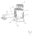
- FIG 1 an exploded view of an insert according to the present invention.
- the insert comprises a tube member 1, an end cover 2, an electrical connection box 3, flexible and/or resilient expansion means 4, a double hinge construction 5 which in this embodiment is provided with a transformer 6 as well as a cover part 7.
- the cover part is designed to be mounted once the entire insert and its connection have been installed through an aperture in an element such that the cover part 7 will cover the aperture and make an aesthetically pleasing finish finish around the insert.
- the tube member 1 may be cylindrical, but not necessarily, and is in this embodiment provided with an opening in either end which will be explained with reference to the following figures.
- the double hinge mechanism 5 is provided with two pivot points 8, 9 such that the hinge flanges 10, 11 may relatively pivot such that the flange 11 may be put in a position where it extends in the same line as the tube 1. In this manner it becomes possible to install the entire installation through an aperture in an element which is of a size corresponding to the outside diameter of the tube 1.
- fastening means 4 In order to fasten the tube 1 on the backside of the element, flexible fastening means 4 are provided where the fastening means include a resilient member 12 which may be moved outside the periphery of the tube member 1 and into engagement with the backside of the plate member (not illustrated).
- the end plate 2 is provided with a number of flanges 13, 14 which may be interfitted with corresponding recesses provided at the top end 15 of the tube member such that after having placed the flange members 13, 14 inside the apertures provided in the end of the tube member 1 and twisting the end plate 2 a strong connection is established between the end plate 2 and the tube 1.
- the flange 11 may advantageously be provided with half circle shaped protrusions. These serve to avoid the flange being entangled in wires, cables or the like placed on the back side of the member into which the insert is mounted. Also when the insert is mounted in ceilings made from wood, the protrusions will act as runners, helping the flange and thereby the insert, passing gaps, grooves and the like which may be present on the surface.
- fastening means 4 it may be seen that by moving the member 21 downwards the end 22 of the resilient member 23 will due to the interaction with the fastening means 24 be made to project outside the periphery of the tube 1 such that it is possible to engage the backside of the plate member into which the insert is to be mounted.
- connection box may be adapted to house 12, 24, 110, 220 or any other voltage installations and is in this embodiment provided with legs 25 such that a distance is maintained between the end plate 2 and the connection box 3 such that the heat developed by the light fixture does not transfer immediately to the electrical connections.
- the cover plate 7 is arranged inside the tube member (not illustrated) by resilient means in the shape of springs 26 such that variations in the plate thickness "a" may be compensated for by adjusting the distance the cover plate 7 is inserted into the tube member 1.
- ridges and grooves may be provided in order to fasten the resilient members 26 in the desired position.
- the upper end of the spring 26 may be provided with a point.
- the ridges/grooves provided on the inside of the tube member may be shaped as a tread, such that the point of the springs may engage the tread.
- socket means may be arranged for inserting a desirable light fixture, for example a socket means of the type GU 10 suitable for providing fixture for halogen lights or standard 220 volt sockets.
Landscapes
- Engineering & Computer Science (AREA)
- General Engineering & Computer Science (AREA)
- Power Engineering (AREA)
- Arrangement Of Elements, Cooling, Sealing, Or The Like Of Lighting Devices (AREA)
- Joining Of Building Structures In Genera (AREA)
- Saccharide Compounds (AREA)
- Valve Device For Special Equipments (AREA)
- Paper (AREA)
- Non-Portable Lighting Devices Or Systems Thereof (AREA)
Priority Applications (2)
| Application Number | Priority Date | Filing Date | Title |
|---|---|---|---|
| PL09168398T PL2157370T3 (pl) | 2008-08-22 | 2009-08-21 | Wkładka uniwersalna |
| DKBA201000167U DK201000167U4 (da) | 2008-08-22 | 2010-09-02 | Indbygningsdåse til indmontering i en væg, loft eller andet element |
Applications Claiming Priority (1)
| Application Number | Priority Date | Filing Date | Title |
|---|---|---|---|
| DKPA200801151 | 2008-08-22 |
Publications (3)
| Publication Number | Publication Date |
|---|---|
| EP2157370A2 true EP2157370A2 (de) | 2010-02-24 |
| EP2157370A3 EP2157370A3 (de) | 2010-10-13 |
| EP2157370B1 EP2157370B1 (de) | 2012-02-15 |
Family
ID=41119953
Family Applications (1)
| Application Number | Title | Priority Date | Filing Date |
|---|---|---|---|
| EP09168398A Not-in-force EP2157370B1 (de) | 2008-08-22 | 2009-08-21 | Anpassbarer Einsatz |
Country Status (4)
| Country | Link |
|---|---|
| EP (1) | EP2157370B1 (de) |
| AT (1) | ATE545828T1 (de) |
| DK (2) | DK2157370T3 (de) |
| PL (1) | PL2157370T3 (de) |
Cited By (3)
| Publication number | Priority date | Publication date | Assignee | Title |
|---|---|---|---|---|
| WO2012052027A1 (en) | 2010-10-20 | 2012-04-26 | Daxtor Aps | An insert |
| EP2518400A1 (de) | 2011-04-14 | 2012-10-31 | Daxtor APS | Eingebaute Montagebox mit Verschlussring |
| EP2602543A1 (de) | 2011-12-05 | 2013-06-12 | Daxtor APS | Montageklammer zur Verwendung bei der Montage von Zubehör für ein Beleuchtungsgerät |
Citations (2)
| Publication number | Priority date | Publication date | Assignee | Title |
|---|---|---|---|---|
| US5664872A (en) | 1993-11-23 | 1997-09-09 | Smiths Industries Plc | Combined lamp and fan assembly |
| US6168299B1 (en) | 1999-04-30 | 2001-01-02 | Ellis Yan | Energy efficient recessed lighting fixture |
Family Cites Families (9)
| Publication number | Priority date | Publication date | Assignee | Title |
|---|---|---|---|---|
| US3700885A (en) * | 1970-10-01 | 1972-10-24 | Air King Corp | Architectural light and adjustment means therefor |
| IT8311958V0 (it) * | 1983-12-09 | 1983-12-09 | Targetti Sankey Spa | Complesso di lume da incassare,con corpo tubolare atto ad essere accolto nella sede |
| US4870549A (en) * | 1987-08-26 | 1989-09-26 | Siemens Aktiengesellschaft | Built-in ceiling light |
| US6116758A (en) * | 1998-03-31 | 2000-09-12 | Lin; Michael | light inlay for various halogen light bulbs, lagging illumination and all necessary accessories |
| US6655813B1 (en) * | 2002-01-07 | 2003-12-02 | Genlyte Thomas Group Llc | Multi-function luminaire |
| CA2373874C (en) * | 2002-02-28 | 2007-10-02 | Canlyte Inc. | Light fixture assembly |
| ITMI20030994A1 (it) * | 2003-05-20 | 2004-11-21 | Ivela S P A | Telaio di supporto per apparecchio illuminante ad incasso. |
| CA2577753C (en) * | 2006-02-17 | 2014-09-23 | Canlyte Inc. | Recessed lighting fixture |
| GB2435722A (en) * | 2006-03-03 | 2007-09-05 | James Christopher Patr Mcenery | Disconnectable electrical fixture |
-
2009
- 2009-08-21 AT AT09168398T patent/ATE545828T1/de active
- 2009-08-21 EP EP09168398A patent/EP2157370B1/de not_active Not-in-force
- 2009-08-21 PL PL09168398T patent/PL2157370T3/pl unknown
- 2009-08-21 DK DK09168398.7T patent/DK2157370T3/da active
-
2010
- 2010-09-02 DK DKBA201000167U patent/DK201000167U4/da not_active IP Right Cessation
Patent Citations (2)
| Publication number | Priority date | Publication date | Assignee | Title |
|---|---|---|---|---|
| US5664872A (en) | 1993-11-23 | 1997-09-09 | Smiths Industries Plc | Combined lamp and fan assembly |
| US6168299B1 (en) | 1999-04-30 | 2001-01-02 | Ellis Yan | Energy efficient recessed lighting fixture |
Cited By (3)
| Publication number | Priority date | Publication date | Assignee | Title |
|---|---|---|---|---|
| WO2012052027A1 (en) | 2010-10-20 | 2012-04-26 | Daxtor Aps | An insert |
| EP2518400A1 (de) | 2011-04-14 | 2012-10-31 | Daxtor APS | Eingebaute Montagebox mit Verschlussring |
| EP2602543A1 (de) | 2011-12-05 | 2013-06-12 | Daxtor APS | Montageklammer zur Verwendung bei der Montage von Zubehör für ein Beleuchtungsgerät |
Also Published As
| Publication number | Publication date |
|---|---|
| EP2157370B1 (de) | 2012-02-15 |
| DK201000167U1 (da) | 2010-09-24 |
| ATE545828T1 (de) | 2012-03-15 |
| EP2157370A3 (de) | 2010-10-13 |
| DK2157370T3 (da) | 2012-05-29 |
| DK201000167U4 (da) | 2010-12-10 |
| PL2157370T3 (pl) | 2012-07-31 |
Similar Documents
| Publication | Publication Date | Title |
|---|---|---|
| US7607935B2 (en) | Insert with ventilation | |
| US9022846B1 (en) | 110 CFM bath fan with and without light | |
| US8636387B1 (en) | Surface-mounted lighting system | |
| US9752765B2 (en) | Fire rated recessed lighting assembly | |
| US6350046B1 (en) | Light fixture | |
| US10907843B2 (en) | Ventilating system and method | |
| CN112350254B (zh) | 用于在天花线内固定电力和通信电缆及相关硬件的系统和方法 | |
| US7874711B2 (en) | Surface-mounted lighting system | |
| US20180127977A1 (en) | Housing apparatus for installation of ceiling or wall-mounted electrical appliances | |
| US20100136897A1 (en) | ventilation cover with a light source | |
| RU2606384C2 (ru) | Встроенный детектор движения встраиваемой полосовой осветительной арматуры | |
| CN106062478A (zh) | 具有多路径冷却的泛光灯 | |
| US9506611B2 (en) | Recessed luminaire with shuttle mechanism for access to electrical components | |
| US6116758A (en) | light inlay for various halogen light bulbs, lagging illumination and all necessary accessories | |
| US20190104585A1 (en) | LED Driver Box | |
| EP2157370B1 (de) | Anpassbarer Einsatz | |
| US20080023894A1 (en) | Captive Retaining Spring | |
| US20060109660A1 (en) | Light fixture | |
| EP2581645B1 (de) | Modularer Strahler | |
| GB2490956A (en) | Lighting unit with demountable lamp housing, fireproofing and removable waterproofing structure | |
| US7484979B2 (en) | Hub assembly | |
| US7329023B2 (en) | Low-power illumination apparatus | |
| US20080198608A1 (en) | Low-Power Illumination Apparatus | |
| US10138896B2 (en) | Recessed motor ceiling fan | |
| US20150369465A1 (en) | Lighting system |
Legal Events
| Date | Code | Title | Description |
|---|---|---|---|
| PUAI | Public reference made under article 153(3) epc to a published international application that has entered the european phase |
Free format text: ORIGINAL CODE: 0009012 |
|
| AK | Designated contracting states |
Kind code of ref document: A2 Designated state(s): AT BE BG CH CY CZ DE DK EE ES FI FR GB GR HR HU IE IS IT LI LT LU LV MC MK MT NL NO PL PT RO SE SI SK SM TR |
|
| AX | Request for extension of the european patent |
Extension state: AL BA RS |
|
| PUAL | Search report despatched |
Free format text: ORIGINAL CODE: 0009013 |
|
| AK | Designated contracting states |
Kind code of ref document: A3 Designated state(s): AT BE BG CH CY CZ DE DK EE ES FI FR GB GR HR HU IE IS IT LI LT LU LV MC MK MT NL NO PL PT RO SE SI SK SM TR |
|
| AX | Request for extension of the european patent |
Extension state: AL BA RS |
|
| 17P | Request for examination filed |
Effective date: 20110413 |
|
| GRAP | Despatch of communication of intention to grant a patent |
Free format text: ORIGINAL CODE: EPIDOSNIGR1 |
|
| RIC1 | Information provided on ipc code assigned before grant |
Ipc: F21V 21/04 20060101AFI20110801BHEP Ipc: F21V 23/02 20060101ALI20110801BHEP |
|
| GRAS | Grant fee paid |
Free format text: ORIGINAL CODE: EPIDOSNIGR3 |
|
| GRAA | (expected) grant |
Free format text: ORIGINAL CODE: 0009210 |
|
| AK | Designated contracting states |
Kind code of ref document: B1 Designated state(s): AT BE BG CH CY CZ DE DK EE ES FI FR GB GR HR HU IE IS IT LI LT LU LV MC MK MT NL NO PL PT RO SE SI SK SM TR |
|
| REG | Reference to a national code |
Ref country code: CH Ref legal event code: EP Ref country code: GB Ref legal event code: FG4D |
|
| REG | Reference to a national code |
Ref country code: IE Ref legal event code: FG4D |
|
| REG | Reference to a national code |
Ref country code: AT Ref legal event code: REF Ref document number: 545828 Country of ref document: AT Kind code of ref document: T Effective date: 20120315 |
|
| REG | Reference to a national code |
Ref country code: DE Ref legal event code: R096 Ref document number: 602009005328 Country of ref document: DE Effective date: 20120419 |
|
| REG | Reference to a national code |
Ref country code: CH Ref legal event code: NV Representative=s name: FIAMMENGHI-FIAMMENGHI |
|
| REG | Reference to a national code |
Ref country code: DK Ref legal event code: T3 |
|
| REG | Reference to a national code |
Ref country code: NL Ref legal event code: T3 |
|
| REG | Reference to a national code |
Ref country code: SE Ref legal event code: TRGR |
|
| REG | Reference to a national code |
Ref country code: NO Ref legal event code: T2 Effective date: 20120215 |
|
| LTIE | Lt: invalidation of european patent or patent extension |
Effective date: 20120215 |
|
| PG25 | Lapsed in a contracting state [announced via postgrant information from national office to epo] |
Ref country code: HR Free format text: LAPSE BECAUSE OF FAILURE TO SUBMIT A TRANSLATION OF THE DESCRIPTION OR TO PAY THE FEE WITHIN THE PRESCRIBED TIME-LIMIT Effective date: 20120215 Ref country code: IS Free format text: LAPSE BECAUSE OF FAILURE TO SUBMIT A TRANSLATION OF THE DESCRIPTION OR TO PAY THE FEE WITHIN THE PRESCRIBED TIME-LIMIT Effective date: 20120615 Ref country code: LT Free format text: LAPSE BECAUSE OF FAILURE TO SUBMIT A TRANSLATION OF THE DESCRIPTION OR TO PAY THE FEE WITHIN THE PRESCRIBED TIME-LIMIT Effective date: 20120215 |
|
| REG | Reference to a national code |
Ref country code: PL Ref legal event code: T3 |
|
| PG25 | Lapsed in a contracting state [announced via postgrant information from national office to epo] |
Ref country code: FI Free format text: LAPSE BECAUSE OF FAILURE TO SUBMIT A TRANSLATION OF THE DESCRIPTION OR TO PAY THE FEE WITHIN THE PRESCRIBED TIME-LIMIT Effective date: 20120215 Ref country code: GR Free format text: LAPSE BECAUSE OF FAILURE TO SUBMIT A TRANSLATION OF THE DESCRIPTION OR TO PAY THE FEE WITHIN THE PRESCRIBED TIME-LIMIT Effective date: 20120516 Ref country code: BE Free format text: LAPSE BECAUSE OF FAILURE TO SUBMIT A TRANSLATION OF THE DESCRIPTION OR TO PAY THE FEE WITHIN THE PRESCRIBED TIME-LIMIT Effective date: 20120215 Ref country code: PT Free format text: LAPSE BECAUSE OF FAILURE TO SUBMIT A TRANSLATION OF THE DESCRIPTION OR TO PAY THE FEE WITHIN THE PRESCRIBED TIME-LIMIT Effective date: 20120615 Ref country code: LV Free format text: LAPSE BECAUSE OF FAILURE TO SUBMIT A TRANSLATION OF THE DESCRIPTION OR TO PAY THE FEE WITHIN THE PRESCRIBED TIME-LIMIT Effective date: 20120215 |
|
| PG25 | Lapsed in a contracting state [announced via postgrant information from national office to epo] |
Ref country code: CY Free format text: LAPSE BECAUSE OF FAILURE TO SUBMIT A TRANSLATION OF THE DESCRIPTION OR TO PAY THE FEE WITHIN THE PRESCRIBED TIME-LIMIT Effective date: 20120215 |
|
| PG25 | Lapsed in a contracting state [announced via postgrant information from national office to epo] |
Ref country code: RO Free format text: LAPSE BECAUSE OF FAILURE TO SUBMIT A TRANSLATION OF THE DESCRIPTION OR TO PAY THE FEE WITHIN THE PRESCRIBED TIME-LIMIT Effective date: 20120215 Ref country code: CZ Free format text: LAPSE BECAUSE OF FAILURE TO SUBMIT A TRANSLATION OF THE DESCRIPTION OR TO PAY THE FEE WITHIN THE PRESCRIBED TIME-LIMIT Effective date: 20120215 Ref country code: EE Free format text: LAPSE BECAUSE OF FAILURE TO SUBMIT A TRANSLATION OF THE DESCRIPTION OR TO PAY THE FEE WITHIN THE PRESCRIBED TIME-LIMIT Effective date: 20120215 Ref country code: SI Free format text: LAPSE BECAUSE OF FAILURE TO SUBMIT A TRANSLATION OF THE DESCRIPTION OR TO PAY THE FEE WITHIN THE PRESCRIBED TIME-LIMIT Effective date: 20120215 |
|
| PG25 | Lapsed in a contracting state [announced via postgrant information from national office to epo] |
Ref country code: SK Free format text: LAPSE BECAUSE OF FAILURE TO SUBMIT A TRANSLATION OF THE DESCRIPTION OR TO PAY THE FEE WITHIN THE PRESCRIBED TIME-LIMIT Effective date: 20120215 Ref country code: IT Free format text: LAPSE BECAUSE OF FAILURE TO SUBMIT A TRANSLATION OF THE DESCRIPTION OR TO PAY THE FEE WITHIN THE PRESCRIBED TIME-LIMIT Effective date: 20120215 |
|
| PLBE | No opposition filed within time limit |
Free format text: ORIGINAL CODE: 0009261 |
|
| STAA | Information on the status of an ep patent application or granted ep patent |
Free format text: STATUS: NO OPPOSITION FILED WITHIN TIME LIMIT |
|
| 26N | No opposition filed |
Effective date: 20121116 |
|
| REG | Reference to a national code |
Ref country code: DE Ref legal event code: R097 Ref document number: 602009005328 Country of ref document: DE Effective date: 20121116 |
|
| PG25 | Lapsed in a contracting state [announced via postgrant information from national office to epo] |
Ref country code: MC Free format text: LAPSE BECAUSE OF NON-PAYMENT OF DUE FEES Effective date: 20120831 |
|
| PG25 | Lapsed in a contracting state [announced via postgrant information from national office to epo] |
Ref country code: ES Free format text: LAPSE BECAUSE OF FAILURE TO SUBMIT A TRANSLATION OF THE DESCRIPTION OR TO PAY THE FEE WITHIN THE PRESCRIBED TIME-LIMIT Effective date: 20120526 |
|
| REG | Reference to a national code |
Ref country code: IE Ref legal event code: MM4A |
|
| PG25 | Lapsed in a contracting state [announced via postgrant information from national office to epo] |
Ref country code: IE Free format text: LAPSE BECAUSE OF NON-PAYMENT OF DUE FEES Effective date: 20120821 Ref country code: BG Free format text: LAPSE BECAUSE OF FAILURE TO SUBMIT A TRANSLATION OF THE DESCRIPTION OR TO PAY THE FEE WITHIN THE PRESCRIBED TIME-LIMIT Effective date: 20120515 |
|
| PG25 | Lapsed in a contracting state [announced via postgrant information from national office to epo] |
Ref country code: MT Free format text: LAPSE BECAUSE OF FAILURE TO SUBMIT A TRANSLATION OF THE DESCRIPTION OR TO PAY THE FEE WITHIN THE PRESCRIBED TIME-LIMIT Effective date: 20120215 |
|
| PG25 | Lapsed in a contracting state [announced via postgrant information from national office to epo] |
Ref country code: TR Free format text: LAPSE BECAUSE OF FAILURE TO SUBMIT A TRANSLATION OF THE DESCRIPTION OR TO PAY THE FEE WITHIN THE PRESCRIBED TIME-LIMIT Effective date: 20120215 |
|
| PG25 | Lapsed in a contracting state [announced via postgrant information from national office to epo] |
Ref country code: LU Free format text: LAPSE BECAUSE OF NON-PAYMENT OF DUE FEES Effective date: 20120821 Ref country code: SM Free format text: LAPSE BECAUSE OF FAILURE TO SUBMIT A TRANSLATION OF THE DESCRIPTION OR TO PAY THE FEE WITHIN THE PRESCRIBED TIME-LIMIT Effective date: 20120215 |
|
| PG25 | Lapsed in a contracting state [announced via postgrant information from national office to epo] |
Ref country code: HU Free format text: LAPSE BECAUSE OF FAILURE TO SUBMIT A TRANSLATION OF THE DESCRIPTION OR TO PAY THE FEE WITHIN THE PRESCRIBED TIME-LIMIT Effective date: 20090821 |
|
| PGFP | Annual fee paid to national office [announced via postgrant information from national office to epo] |
Ref country code: CH Payment date: 20140827 Year of fee payment: 6 Ref country code: NL Payment date: 20140826 Year of fee payment: 6 |
|
| PGFP | Annual fee paid to national office [announced via postgrant information from national office to epo] |
Ref country code: PL Payment date: 20140806 Year of fee payment: 6 Ref country code: AT Payment date: 20140801 Year of fee payment: 6 |
|
| PG25 | Lapsed in a contracting state [announced via postgrant information from national office to epo] |
Ref country code: MK Free format text: LAPSE BECAUSE OF FAILURE TO SUBMIT A TRANSLATION OF THE DESCRIPTION OR TO PAY THE FEE WITHIN THE PRESCRIBED TIME-LIMIT Effective date: 20120215 |
|
| REG | Reference to a national code |
Ref country code: FR Ref legal event code: PLFP Year of fee payment: 7 |
|
| PGFP | Annual fee paid to national office [announced via postgrant information from national office to epo] |
Ref country code: NO Payment date: 20150827 Year of fee payment: 7 Ref country code: DE Payment date: 20150827 Year of fee payment: 7 Ref country code: DK Payment date: 20150825 Year of fee payment: 7 Ref country code: GB Payment date: 20150827 Year of fee payment: 7 |
|
| PGFP | Annual fee paid to national office [announced via postgrant information from national office to epo] |
Ref country code: SE Payment date: 20150827 Year of fee payment: 7 Ref country code: FR Payment date: 20150817 Year of fee payment: 7 |
|
| REG | Reference to a national code |
Ref country code: CH Ref legal event code: PL |
|
| REG | Reference to a national code |
Ref country code: AT Ref legal event code: MM01 Ref document number: 545828 Country of ref document: AT Kind code of ref document: T Effective date: 20150821 |
|
| PG25 | Lapsed in a contracting state [announced via postgrant information from national office to epo] |
Ref country code: CH Free format text: LAPSE BECAUSE OF NON-PAYMENT OF DUE FEES Effective date: 20150831 Ref country code: LI Free format text: LAPSE BECAUSE OF NON-PAYMENT OF DUE FEES Effective date: 20150831 |
|
| REG | Reference to a national code |
Ref country code: NL Ref legal event code: MM Effective date: 20150901 |
|
| PG25 | Lapsed in a contracting state [announced via postgrant information from national office to epo] |
Ref country code: AT Free format text: LAPSE BECAUSE OF NON-PAYMENT OF DUE FEES Effective date: 20150821 |
|
| PG25 | Lapsed in a contracting state [announced via postgrant information from national office to epo] |
Ref country code: NL Free format text: LAPSE BECAUSE OF NON-PAYMENT OF DUE FEES Effective date: 20150901 |
|
| PG25 | Lapsed in a contracting state [announced via postgrant information from national office to epo] |
Ref country code: PL Free format text: LAPSE BECAUSE OF NON-PAYMENT OF DUE FEES Effective date: 20150821 |
|
| REG | Reference to a national code |
Ref country code: DE Ref legal event code: R119 Ref document number: 602009005328 Country of ref document: DE |
|
| REG | Reference to a national code |
Ref country code: DK Ref legal event code: EBP Effective date: 20160831 Ref country code: NO Ref legal event code: MMEP |
|
| REG | Reference to a national code |
Ref country code: SE Ref legal event code: EUG |
|
| GBPC | Gb: european patent ceased through non-payment of renewal fee |
Effective date: 20160821 |
|
| PG25 | Lapsed in a contracting state [announced via postgrant information from national office to epo] |
Ref country code: SE Free format text: LAPSE BECAUSE OF NON-PAYMENT OF DUE FEES Effective date: 20160822 Ref country code: NO Free format text: LAPSE BECAUSE OF NON-PAYMENT OF DUE FEES Effective date: 20160831 |
|
| REG | Reference to a national code |
Ref country code: FR Ref legal event code: ST Effective date: 20170428 |
|
| PG25 | Lapsed in a contracting state [announced via postgrant information from national office to epo] |
Ref country code: FR Free format text: LAPSE BECAUSE OF NON-PAYMENT OF DUE FEES Effective date: 20160831 Ref country code: DE Free format text: LAPSE BECAUSE OF NON-PAYMENT OF DUE FEES Effective date: 20170301 Ref country code: GB Free format text: LAPSE BECAUSE OF NON-PAYMENT OF DUE FEES Effective date: 20160821 Ref country code: DK Free format text: LAPSE BECAUSE OF NON-PAYMENT OF DUE FEES Effective date: 20160831 |