EP2157379B1 - Humidificateur et système de pile à combustible - Google Patents
Humidificateur et système de pile à combustible Download PDFInfo
- Publication number
- EP2157379B1 EP2157379B1 EP08764819.2A EP08764819A EP2157379B1 EP 2157379 B1 EP2157379 B1 EP 2157379B1 EP 08764819 A EP08764819 A EP 08764819A EP 2157379 B1 EP2157379 B1 EP 2157379B1
- Authority
- EP
- European Patent Office
- Prior art keywords
- gas
- humidifier
- outlet
- inlet
- permeable membrane
- Prior art date
- Legal status (The legal status is an assumption and is not a legal conclusion. Google has not performed a legal analysis and makes no representation as to the accuracy of the status listed.)
- Active
Links
Images


Classifications
-
- H—ELECTRICITY
- H01—ELECTRIC ELEMENTS
- H01M—PROCESSES OR MEANS, e.g. BATTERIES, FOR THE DIRECT CONVERSION OF CHEMICAL ENERGY INTO ELECTRICAL ENERGY
- H01M8/00—Fuel cells; Manufacture thereof
- H01M8/04—Auxiliary arrangements, e.g. for control of pressure or for circulation of fluids
- H01M8/04082—Arrangements for control of reactant parameters, e.g. pressure or concentration
- H01M8/04089—Arrangements for control of reactant parameters, e.g. pressure or concentration of gaseous reactants
- H01M8/04119—Arrangements for control of reactant parameters, e.g. pressure or concentration of gaseous reactants with simultaneous supply or evacuation of electrolyte; Humidifying or dehumidifying
- H01M8/04126—Humidifying
-
- F—MECHANICAL ENGINEERING; LIGHTING; HEATING; WEAPONS; BLASTING
- F24—HEATING; RANGES; VENTILATING
- F24F—AIR-CONDITIONING; AIR-HUMIDIFICATION; VENTILATION; USE OF AIR CURRENTS FOR SCREENING
- F24F6/00—Air-humidification, e.g. cooling by humidification
- F24F6/02—Air-humidification, e.g. cooling by humidification by evaporation of water in the air
- F24F6/04—Air-humidification, e.g. cooling by humidification by evaporation of water in the air using stationary unheated wet elements
-
- H—ELECTRICITY
- H01—ELECTRIC ELEMENTS
- H01M—PROCESSES OR MEANS, e.g. BATTERIES, FOR THE DIRECT CONVERSION OF CHEMICAL ENERGY INTO ELECTRICAL ENERGY
- H01M8/00—Fuel cells; Manufacture thereof
- H01M8/04—Auxiliary arrangements, e.g. for control of pressure or for circulation of fluids
-
- H—ELECTRICITY
- H01—ELECTRIC ELEMENTS
- H01M—PROCESSES OR MEANS, e.g. BATTERIES, FOR THE DIRECT CONVERSION OF CHEMICAL ENERGY INTO ELECTRICAL ENERGY
- H01M8/00—Fuel cells; Manufacture thereof
- H01M8/04—Auxiliary arrangements, e.g. for control of pressure or for circulation of fluids
- H01M8/04082—Arrangements for control of reactant parameters, e.g. pressure or concentration
- H01M8/04089—Arrangements for control of reactant parameters, e.g. pressure or concentration of gaseous reactants
- H01M8/04119—Arrangements for control of reactant parameters, e.g. pressure or concentration of gaseous reactants with simultaneous supply or evacuation of electrolyte; Humidifying or dehumidifying
- H01M8/04126—Humidifying
- H01M8/04141—Humidifying by water containing exhaust gases
-
- H—ELECTRICITY
- H01—ELECTRIC ELEMENTS
- H01M—PROCESSES OR MEANS, e.g. BATTERIES, FOR THE DIRECT CONVERSION OF CHEMICAL ENERGY INTO ELECTRICAL ENERGY
- H01M8/00—Fuel cells; Manufacture thereof
- H01M8/04—Auxiliary arrangements, e.g. for control of pressure or for circulation of fluids
- H01M8/04082—Arrangements for control of reactant parameters, e.g. pressure or concentration
- H01M8/04089—Arrangements for control of reactant parameters, e.g. pressure or concentration of gaseous reactants
- H01M8/04119—Arrangements for control of reactant parameters, e.g. pressure or concentration of gaseous reactants with simultaneous supply or evacuation of electrolyte; Humidifying or dehumidifying
- H01M8/04126—Humidifying
- H01M8/04149—Humidifying by diffusion, e.g. making use of membranes
-
- F—MECHANICAL ENGINEERING; LIGHTING; HEATING; WEAPONS; BLASTING
- F24—HEATING; RANGES; VENTILATING
- F24F—AIR-CONDITIONING; AIR-HUMIDIFICATION; VENTILATION; USE OF AIR CURRENTS FOR SCREENING
- F24F3/00—Air-conditioning systems in which conditioned primary air is supplied from one or more central stations to distributing units in the rooms or spaces where it may receive secondary treatment; Apparatus specially designed for such systems
- F24F3/12—Air-conditioning systems in which conditioned primary air is supplied from one or more central stations to distributing units in the rooms or spaces where it may receive secondary treatment; Apparatus specially designed for such systems characterised by the treatment of the air otherwise than by heating and cooling
- F24F3/14—Air-conditioning systems in which conditioned primary air is supplied from one or more central stations to distributing units in the rooms or spaces where it may receive secondary treatment; Apparatus specially designed for such systems characterised by the treatment of the air otherwise than by heating and cooling by humidification; by dehumidification
- F24F2003/1435—Air-conditioning systems in which conditioned primary air is supplied from one or more central stations to distributing units in the rooms or spaces where it may receive secondary treatment; Apparatus specially designed for such systems characterised by the treatment of the air otherwise than by heating and cooling by humidification; by dehumidification comprising semi-permeable membrane
-
- H—ELECTRICITY
- H01—ELECTRIC ELEMENTS
- H01M—PROCESSES OR MEANS, e.g. BATTERIES, FOR THE DIRECT CONVERSION OF CHEMICAL ENERGY INTO ELECTRICAL ENERGY
- H01M8/00—Fuel cells; Manufacture thereof
- H01M8/10—Fuel cells with solid electrolytes
- H01M2008/1095—Fuel cells with polymeric electrolytes
-
- Y—GENERAL TAGGING OF NEW TECHNOLOGICAL DEVELOPMENTS; GENERAL TAGGING OF CROSS-SECTIONAL TECHNOLOGIES SPANNING OVER SEVERAL SECTIONS OF THE IPC; TECHNICAL SUBJECTS COVERED BY FORMER USPC CROSS-REFERENCE ART COLLECTIONS [XRACs] AND DIGESTS
- Y02—TECHNOLOGIES OR APPLICATIONS FOR MITIGATION OR ADAPTATION AGAINST CLIMATE CHANGE
- Y02E—REDUCTION OF GREENHOUSE GAS [GHG] EMISSIONS, RELATED TO ENERGY GENERATION, TRANSMISSION OR DISTRIBUTION
- Y02E60/00—Enabling technologies; Technologies with a potential or indirect contribution to GHG emissions mitigation
- Y02E60/30—Hydrogen technology
- Y02E60/50—Fuel cells
Definitions
- the present invention relates to a humidifier and a fuel cell system.
- a humidifier which is effective for the improvement of a countermeasure against freezing in the winter, a cold district or the like.
- a fuel cell system includes a fuel cell which generates a power by an electrochemical reaction between a fuel gas and an oxidizing gas.
- a fuel cell which generates a power by an electrochemical reaction between a fuel gas and an oxidizing gas.
- an electrolyte film needs to be held in a humid state. This humid state is usually held by a humidifier which humidifies the fuel gas or the oxidizing gas.
- an internal humidifying system which performs water exchange between a highly humid oxidizing offgas and a lowly humid oxidizing gas is frequently employed.
- the oxidizing offgas is more humid than the oxidizing gas, because the oxidizing offgas discharged from an air electrode of the fuel cell contains water generated by the electrochemical reaction.
- JP 2005-44665 A discloses a humidifier of the internal humidifying system which includes a hollow fiber membrane having steam permeability in a case thereof.
- the upper part of the case is provided with an inlet and an outlet for the oxidizing gas, and both the side parts of the case are provided with an inlet and an outlet for the oxidizing offgas.
- the oxidizing offgas and the oxidizing gas are introduced into the case, and the respective gases flow outside and inside the hollow fiber membrane.
- a water is absorbed from the highly humid oxidizing offgas by the hollow fiber membrane, and the water passes through the membrane by a capillary phenomenon to move to the lowly humid oxidizing gas, whereby the oxidizing gas is replenished with the water.
- JP 2005-44665 A does not disclose any countermeasure against freezing in the humidifier. In consequence, the following problems might occur.
- the ice might be flied by an introduced oxidizing offgas to come in contact with the hollow fiber membrane, and might damage the hollow fiber membrane.
- the ice formed in the bottom of the case might damage the hollow fiber membrane by the flow of an oxidizing gas.
- an object of the present invention is to provide a humidifier capable of inhibiting a steam permeable membrane from being damaged at low temperatures, and a fuel cell system. This objected is solved by a humidifier according to claim 1 or claim 2 and by a fuel cell according to claim 8. Preferred embodiments of the humidifier are described in claims 3 to 7.
- the humidifier according to claim 1 is mounted in a mobile body.
- the humidifier is provided therein with a steam permeable membrane, and introduces thereinto a first gas and a second gas having a humidity higher than that of the first gas to humidify the first gas by the second gas via the steam permeable membrane.
- the humidifier comprises inlets and outlets for the first gas and the second gas, respectively, the inlets and outlets being communicated with the inside thereof.
- the humidifier comprises a housing which surrounds the steam permeable membrane, wherein a gap is provided between the housing and the steam permeable membrane.
- the humidifier satisfies the following (a) and (b):
- a fuel cell system of the present invention comprises a fuel cell which generates a power by an electrochemical reaction between an oxidizing gas and a fuel gas, wherein by use of the humidifier of the present invention, at least one of the oxidizing gas and the fuel gas to be fed to the fuel cell is humidified.
- a portion where water included in the first gas and/or the second gas condenses and accumulates, and a portion where the water condenses into ice at a low temperature are not positioned on a high inlet side but are positioned on a low outlet side, and can further be positioned on the downstream side of the first gas and/or the second gas.
- a low temperature e.g., at 0°C
- the ice and the water are inhibited from being directed to the steam permeable membrane due to the flow. Therefore, the steam permeable membrane can be inhibited from being damaged.
- the low-temperature startup properties thereof can be improved.
- the position of the steam permeable membrane may be lower than the inlet for the first gas but higher than the outlet for the first gas. Moreover, according to one preferable configuration, the position of the steam permeable membrane may be lower than the inlet for the second gas but higher than the outlet for the second gas.
- water formed in the bottom of the housing moves to the outlet side owing to gravity. According to this constitution, even when the water condenses in the steam permeable membrane, the water moves to an outlet side owing to gravity. In consequence, the water can be inhibited from being accumulated in the steam permeable membrane, and the steam permeable membrane can be inhibited from being frozen.
- At least a part of the inlet for the first gas is higher than the upper limit position of the steam permeable membrane, and at least a part of the outlet for the first gas is lower than the lower limit position of the steam permeable membrane.
- at least a part of the inlet for the second gas may be higher than the upper limit position of the steam permeable membrane, and at least a part of the outlet for the second gas may be lower than the lower limit position of the steam permeable membrane.
- the water can be inhibited from being accumulated in the steam permeable membrane, and the steam permeable membrane can be inhibited from being frozen.
- the steam permeable membrane either a flat membrane or a hollow fiber membrane may be employed.
- the steam permeable membrane may be the hollow fiber membrane, the first gas may flow outside the hollow fiber membrane, and the second gas may flow through the hollow fiber membrane.
- the humidifier may be connected to a pipe through which the first gas or the second gas flows to communicate with the inside of the humidifier.
- the pipe may be provided with a valve having a valve body located at a position higher than that of the humidifier in a gravity direction.
- the water which has condensed in the humidifier can be inhibited from being accumulated in the valve body.
- the operation defect of the valve body due to the freezing can be inhibited from being generated.
- the humidifier may comprise a case which is provided with the inlets and the outlets for the first gas and the second gas, respectively, and in which the steam permeable membrane is disposed.
- Another humidifier of the present invention for achieving the above object according to claim 2 is a humidifier mounted in a mobile body.
- the humidifier is provided with a steam permeable membrane in a case and introduces thereinto a first gas and a second gas having a humidity higher than that of the first gas to humidify the first gas by the second gas via the steam permeable membrane.
- the case comprises an inlet and an outlet for the first gas communicated with the inside of the humidifier, an inlet and an outlet for the second gas communicated with the inside of the humidifier, and an inner wall that connects the inlet for the second gas and the steam permeable membrane.
- the inlet for the first gas is located at a position higher than the outlet for the first gas.
- the inlet for the second gas is located at a position higher than the outlet for the second gas.
- At least a part of the inlet for the second gas is higher than the upper limit position of the steam permeable membrane and at least a part of the outlet for the second gas is lower than the lower limit position of the steam permeable membrane. Further, the inner wall of the case positioned below the inlet for the second gas inwardly tilts downwards.
- the water condenses or the condensed water becomes ice at a portion in the lower position of the case, and the portion can be located on the downstream side of the first gas and/or the second gas.
- the condensed water or the ice can be inhibited from being directed to the steam permeable membrane by the flow. Therefore, the steam permeable membrane can be inhibited from being damaged.
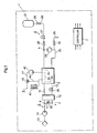
- a fuel cell system 1 includes a fuel cell 2, an oxidizing gas piping system 3, a fuel gas piping system 4, a refrigerant piping system 5, and a controller 7.
- the fuel cell system 1 can be mounted in a vehicle, but is, needless to say, applicable to not only the vehicle but also various mobile bodies (e.g., a ship, an airplane, a robot, etc.) and a stational power source.
- the fuel cell 2 has a stack structure in which a large number of unit cells are stacked.
- Each unit cell of a solid polymer electrolyte type has an air electrode on one surface of an electrolyte, and a fuel electrode on the other surface thereof, and further has a pair of separators which sandwich the air electrode and the fuel electrode from both sides thereof.
- An oxidizing gas is fed to an oxidizing gas passage 2a of one of the separators, and a fuel gas is fed to a fuel gas passage 2b of the other separator.
- the fuel cell 2 By an electrochemical reaction between the fed fuel gas and oxidizing gas, the fuel cell 2 generates a power.
- the fuel cell 2 generates heat and also forms water on the side of the air electrode.
- the temperature of the solid polymer electrolyte type fuel cell 2 is about 60 to 80°C.
- the oxidizing gas piping system 3 has a supply path 11 and a discharge path 12.
- the supply path 11 the oxidizing gas to be fed to the oxidizing gas passage 2a flows.
- the discharge path 12 the oxidizing offgas discharged from the oxidizing gas passage 2a flows.
- the oxidizing offgas contains the water formed by the electrochemical reaction in the fuel cell 2 and hence has a highly humid state.
- a compressor 14 is provided in the supply path 11, and takes outside air as the oxidizing gas via an air cleaner 13 so as to feed the gas under pressure to the fuel cell 2.
- the oxidizing gas fed under pressure is appropriately humidified by water exchange performed between the oxidizing gas and the oxidizing offgas by a humidifier 15.
- An air pressure regulation valve 16 is disposed around an air electrode outlet of the discharge path 12 to regulate a back pressure on the side of the air electrode.
- a bypass path 17 connects the supply path 11 to the discharge path 12 so that the oxidizing gas flows to bypass the fuel cell 2.
- the bypass path 17 is connected to the supply path 11 at a connection point B on the upstream side of the humidifier 15, and is connected to the discharge path 12 at a connection point C on the downstream side of the humidifier 15.
- the oxidizing offgas is finally discharged as an exhaust gas from the system to the outside air through a muffler (not shown).
- a bypass valve 18 provided in the bypass path 17 is opened, whereby a part of the oxidizing gas is branched to the bypass path 17 and guided to the muffler.
- the bypassed oxidizing gas dilutes so-called pumping hydrogen discharged to the discharge path 12 during a low-efficiency operation.
- the fuel gas piping system 4 feeds and discharges a hydrogen gas as the fuel gas to and from the fuel cell 2.
- the fuel gas piping system 4 has a hydrogen supply source 21, a supply path 22, a circulation path 23, a pump 24, and a purging path 25.
- the hydrogen gas is discharged from the hydrogen supply source 21 to the supply path 22 by opening a source valve 26, and is fed to the fuel gas passage 2b through a regulation valve 27 and a shut valve 28.
- the hydrogen gas is discharged as a hydrogen offgas from the fuel gas passage 2b to the circulation path 23.
- the hydrogen offgas is returned to a joining part A between the circulation path 23 and the supply path 22 by the pump 24, and is fed to the fuel gas passage 2b again.
- a part of the hydrogen offgas is discharged from the circulation path 23 to the purging path 25 by appropriately opening a purging valve 33, and discharged externally from the system through a hydrogen diluter (not shown).
- the refrigerant piping system 5 circulates a refrigerant (e.g., cooling water) through a cooling passage 2c in the fuel cell 2, and holds the fuel cell 2 at a predetermined operation temperature.
- the cooling passage 2c is connected to a refrigerant passage 41 through which the refrigerant circulates across the fuel cell 2 and a radiator 43.
- the refrigerant is fed under pressure to the cooling passage 2c by a cooling pump 42, discharged from the cooling passage 2c and then cooled by the radiator 43.
- a bypass passage 44 is connected to the refrigerant passage 41 so that the refrigerant flows to bypass the radiator 43.
- a switch valve 45 is a control valve which sets the circulation of the refrigerant across the radiator 43 and the bypass passage 44.
- the controller 7 has a constitution of a microcomputer including therein a CPU, an ROM and an RAM, and generally controls the system 1.
- the CPU executes desired calculation according to a control program to perform various processing and control.
- the ROM stores a control program or control data to be processed by the CPU.
- the RAM is mainly used as various operation regions for control processing.
- the controller 7 inputs detection signals from various sensors such as a pressure sensor and a temperature sensor, and outputs control signals to constituent elements.
- FIG. 2 is a perspective view showing the appearance of the humidifier 15
- FIG. 3 is a sectional front view showing the inside of the humidifier 15.
- the humidifier 15 employs an internal humidifying system, and humidifies the lowly humid oxidizing gas with the highly humid oxidizing offgas.
- the humidifier 15 has a box-like case 71.
- a front surface 71 a of the case 71 is provided with an inlet 72 IN and an outlet 72 OUT connected to an inlet pipe 11 IN and an outlet pipe 11 OUT for the oxidizing gas, respectively.
- the front surface 71 a is provided with an inlet 73 IN and an outlet 73 OUT connected to an inlet pipe 12 IN and an outlet pipe 12 OUT for the oxidizing offgas, respectively.
- the inlets 72 IN , 73 IN and the outlets 72 OUT , 73 OUT are portions which connect the inside of the case 71 to the outside thereof and which may be referred to as connecting portions with respect to pipes outside the case 71, communicating portions or openings. It is to be noted that four portions shown by dotted circles in FIG. 3 correspond to the inlets 72 IN , 73 IN and the outlets 72 OUT , 73 OUT , respectively.
- the inlet pipe 11 IN and the outlet pipe 11 OUT are connected to each other through the case 71 to constitute the supply path 11.
- the inlet pipe 11 IN has one end thereof connected to the inlet 72 IN to introduce the oxidizing gas into the case 71.
- the outlet pipe 11 OUT has one end thereof connected to the outlet 72 OUT , and the other end thereof connected to the fuel cell 2, whereby the oxidizing gas humidified by the humidifier 15 is discharged externally from the case 71, and fed to the fuel cell 2.
- the inlet pipe 12 IN and the outlet pipe 12 OUT are connected to each other through the case 71 to constitute the discharge path 12.
- the inlet pipe 12 IN has one end thereof connected to the inlet 73 IN , and the other end thereof connected to the fuel cell 2, to introduce the oxidizing offgas discharged from the fuel cell 2 into the case 71.
- the outlet pipe 12 OUT has one end thereof connected to the outlet 73 OUT to discharge the oxidizing offgas used for the humidification externally from the case 71.
- a bunch 81 of hollow fiber membranes (hereinafter referred to as "the hollow fiber membrane bunch 81") is provided in the case 71.
- the hollow fiber membrane bunch 81 a large number of known hollow fiber membranes 82 each having an inner diameter of, for example, about several hundred ⁇ m are bunched.
- Each hollow fiber membrane 82 is a filter member having steam permeability, and may preferably have such characteristics that only steam permeates the membrane.
- the oxidizing gas flows, and inside the hollow fiber membranes (hollow portions), the oxidizing offgas flows.
- the water of the highly humid oxidizing offgas is absorbed by the hollow fiber membranes 82, and is drawn up to the outer peripheries of the membranes by a capillary phenomenon, to move to the lowly humid oxidizing gas passing by the outer peripheries of the hollow fiber membranes 82.
- the oxidizing gas is humidified.
- portions connected to the pipes may be changed, whereby outside the hollow fiber membranes 82, the oxidizing offgas flows, and inside the membranes, the oxidizing gas flows.
- the hollow fiber membrane bunch 81 is received in a housing 83 which surrounds the periphery of the bunch.
- the housing 83 has a cylindrical shape with both open ends in a longitudinal direction (the horizontal direction) thereof, and extends in the horizontal direction with a length substantially equal to that of the hollow fiber membrane bunch 81.
- the housing 83 is received in the case 71 while a space between the outer wall of the housing and the case 71 is sealed with a plurality of O-rings 84.
- the peripheral wall of the housing 83 is provided with a hole 85 IN for introducing the oxidizing gas and a hole 85 OUT for discharging the oxidizing gas.
- One or more holes 85 IN and one or more holes 85 OUT each having a peripheral direction are formed at positions corresponding to the inlet 72 IN and the outlet 72 OUT in the longitudinal direction, respectively.
- Both ends of the hollow fiber membrane bunch 81 in an axial direction are provided with potting portions 88 for air-tightly and liquid-tightly closing a gap between the hollow fiber membranes 82 and 82 and a gap between the hollow fiber membranes 82 and the housing 83.
- the potting portions 88 are formed by potting, for example, an adhesive therein, whereby the hollow fiber membrane bunch 81 is fixed to both the ends of the housing 83.
- the potting portions 88 prevent the oxidizing offgas flowing through the hollow portions of the hollow fiber membranes 82 from being brought into direct contact with the oxidizing gas flowing outside the hollow fiber membranes 82 in the housing 83, and water exchange between both the gases is performed via the hollow fiber membranes 82.
- the inlet 72 IN for the oxidizing gas is located at a position higher than that of the outlet 72 OUT therefor in a gravity direction, and the hollow fiber membrane bunch 81 is positioned between the inlet 72 IN and the outlet 72 OUT .
- the inlet 73 IN for the oxidizing offgas is located at a position higher than that of the outlet 73 OUT therefor in the gravity direction, and the hollow fiber membrane bunch 81 is positioned between the inlet 73 IN and the outlet 73 OUT . It is to be noted that also when the humidifier 15 is mounted in a mobile body such as a vehicle, such a positional relation in the gravity direction may be provided.
- the oxidizing gas is introduced into the case 71 through the inlet 72 IN , and then introduced into the housing 83 through the hole 85 IN to flow through the gap between the housing 83 and the hollow fiber membranes 82 and the gap between the hollow fiber membranes 82 and 82.
- the oxidizing gas humidified by the hollow fiber membranes 82 is discharged externally from the housing 83 through the hole 85 OUT , and is finally discharged externally from the case 71 through the outlet 72 OUT .
- the oxidizing gas flows from the higher position to the lower position in the gravity direction across the inlet 72 IN and the outlet 72 OUT .
- the oxidizing offgas is introduced into the case 71 through the inlet 73 IN , flows obliquely downwards outside the housing 83, and flows from one end of each hollow fiber membrane 82 into each membrane. Then, the oxidizing offgas horizontally flows from one end of each hollow fiber membrane 82 to the other end thereof (from the right end of FIG. 3 to the left end thereof), while the water in the oxidizing offgas is absorbed by the hollow fiber membranes 82. Afterward, the oxidizing offgas flows from the other end of each hollow fiber membrane 82, flows obliquely downwards outside the housing 83, and is then finally discharged externally from the case 71 through the outlet 73 OUT . In the series of flows, the oxidizing offgas flows from the higher position to the lower position in the gravity direction across the inlet 73 IN and the outlet 73 OUT .
- the case 71 is configured so that the water included in the oxidizing offgas is not easily accumulated.
- the box-like shape of the case 71 including a top wall 91, a bottom wall 92 and a pair of side walls 93, 94 is a nearly point-symmetric shape.
- the side wall 93 includes a vertical wall 101 continuing from the top wall 91 to the downside, a vertical wall 102 continuing from the bottom wall 92 to the upside, and a curved wall 103 extending between the vertical walls 101 and 102 to protrude outwards.
- the inlet 73 IN is positioned in an upper part inside the curved wall 103, and an inner wall 103a of the curved wall 103 positioned below the inlet 73 IN inwardly tilts downwards.
- the lower end of the inner wall 103a continues to the vertical wall 102 via none of horizontal portions.
- the side wall 94 includes a vertical wall 111 continuing from the top wall 91 to the downside, a vertical wall 112 continuing from the bottom wall 92 to the upside, and a curved wall 113 extending between the vertical walls 111 and 112 to protrude outwards.
- the outlet 73 OUT is positioned in a lower part inside the curved wall 113, and an inner wall 113a of the curved wall 113 positioned above the outlet 73 OUT outwardly tilts downwards.
- the inlet 72 IN of the oxidizing gas, the hollow fiber membrane bunch 81 and the outlet 72 OUT have a height level in this order. In consequence, even if moisture included in the oxidizing gas becomes water owing to condensation or the like, this water does not easily accumulate on the side of the inlet 72 IN , and accumulates on the side of the outlet 72 OUT .
- the inlet 73 IN of the oxidizing offgas, the hollow fiber membrane bunch 81 and the outlet 73 OUT are located at the higher positions of the gravity direction in this order. In consequence, even if moisture included in the oxidizing offgas becomes water owing to condensation or the like, this water does not easily accumulate on the side of the inlet 73 IN , and accumulates on the side of the outlet 73 OUT .
- the ice forming portion is on the side of the outlets 72 OUT and 73 OUT , which is the downstream side of the flows of the oxidizing gas and the oxidizing offgas. Therefore, during the next startup of the fuel cell system 1, the oxidizing gas and the oxidizing offgas introduced into the case 71 can inhibit the ice or condensed water from being flied toward the hollow fiber membrane bunch 81, so that the damaging of the hollow fiber membrane bunch 81 can be inhibited.
- the condensed water accumulates on the side of the outlets 72 OUT and 73 OUT , so that the freezing of the hollow fiber membrane bunch 81 can also be inhibited.
- the freezing of the humidifier 15 can be inhibited, and hence the low-temperature startup properties of the fuel cell system 1 can be improved.
- the humidifier 15 may humidify the fuel gas to be supplied to the fuel cell 2.
- a dry gas (a first gas) to be humidified is the oxidizing gas or the fuel gas
- a humid gas (a second gas) used for humidifying these gases is not limited to the oxidizing offgas or a fuel off gas, and may be a gas which is irrelevant to the operation of the fuel cell 2.
- gases caused to flow inside and outside the hollow fiber membranes 82 any gas may be caused to flow inside the hollow fiber membranes 82 as long as the gas is a combination of an inflow gas to the humidifier 15 and an outflow gas from the humidifier 15.
- all portions of the inlets 72 IN and 73 IN do not have to be higher than the hollow fiber membrane bunch 81, and similarly all portions of the outlets 72 OUT and 73 OUT do not have to be lower than the hollow fiber membrane bunch 81.
- the portion of the inlet 72 IN located at the highest position of the inlet may be located higher than an upper limit position 121 of the hollow fiber membrane bunch 81, that is, the highest position of the bunch, and a part of the inlet 72 IN may be located lower than the upper limit position 121 of the hollow fiber membrane bunch 81. This respect also applies to the inlet 73 IN .
- the portion of the outlet 72 OUT located at the lowest position of the outlet may be located lower than a lower limit position 122 of the hollow fiber membrane bunch 81, that is, the lowest position of the bunch, and a part of the outlet 72 OUT may be located higher than the lower limit position 122 of the hollow fiber membrane bunch 81.
- This respect also applies to the outlet 73 OUT .
- the freezing of the hollow fiber membrane bunch 81 can be inhibited.
- the inlet 72 IN of the oxidizing gas is disposed in a position lower than the outlet 72 OUT
- the inlet 73 IN of the oxidizing offgas is disposed in a position higher than the outlet 73 OUT .
- Such a constitution may be employed in which the height levels of the outlet and the inlet of one of the oxidizing gas and the oxidizing offgas are reversed.
- the hollow fiber membrane 82 is used as a steam permeable membrane, but instead of this membrane, a flat membrane type may be used.
- the embodiment is different from the first embodiment in that a positional relation between each valve disposed around a humidifier 15 and the humidifier 15 is regulated.
- the outlet pipe 11 OUT and the inlet pipe 12 IN are provided with shut valves 201, 202, respectively.
- the bypass path 17 which connects the inlet pipe 11 IN to the outlet pipe 12 OUT is provided with the bypass valve 18 as described above.
- a hydrogen diluter 203 and a muffler 204 are provided on the downstream side of the outlet pipe 12 OUT . It is to be noted that the air cleaner 13 and the air regulation valve 16 in the fuel cell system 1 of the first embodiment are omitted from the drawing.
- the shut valve 201, the shut valve 202 and the bypass valve 18 include valve bodies disposed in positions higher than the outlet 12 OUT , the inlet 73 IN and the outlet 73 OUT in a gravity direction, respectively.
- a height positional relation between the valve body of the shut valve 201 and the outlet 72 OUT will be described as an example, but needless to say, this relation also applies to the shut valve 202 and the bypass valve 18.
- the constitution of the humidifier 15 is omitted.
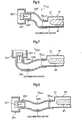
- a hose 210 as a part of the outlet pipe 11 OUT is connected to the outlet 72 OUT , and the other end thereof is connected to an outflow port 220 of the shut valve 201.
- the hose 210 bends upwards and extends across the outlet 72 OUT and the outflow port 220.
- the shut valve 201 comprises, for example, an electromagnetic valve, and a valve body 221 moves in a horizontal direction by an electromagnetic force to open or close the outflow port 220.
- the valve body 221 is positioned at the same height level as that of the outflow port 220, and is disposed in the position higher than the outlet 72 OUT .
- FIG. 7 or 8 may be employed.
- the hose 210 between the outlet 72 OUT and the outflow port 220 may have a portion 230 positioned below them.
- the portion 230 disposed in the lowest position of the gravity direction is provided in the hose 210, whereby the water discharged from the outlet 72 OUT accumulates in the portion 230.
- a portion 240 positioned below the outlet 72 OUT and the outflow port 220 may be set in the hose 210. Also in this case, the water discharged from the outlet 72 OUT accumulates in the portion 240.
Landscapes
- Engineering & Computer Science (AREA)
- Chemical & Material Sciences (AREA)
- Chemical Kinetics & Catalysis (AREA)
- Sustainable Development (AREA)
- Sustainable Energy (AREA)
- Manufacturing & Machinery (AREA)
- Life Sciences & Earth Sciences (AREA)
- Electrochemistry (AREA)
- General Chemical & Material Sciences (AREA)
- Fuel Cell (AREA)
- Combustion & Propulsion (AREA)
- Mechanical Engineering (AREA)
- General Engineering & Computer Science (AREA)
- Air Humidification (AREA)
Claims (8)
- Humidificateur monté sur un corps mobile qui est prévu à l'intérieur de ce dernier avec une membrane perméable à la vapeur et qui y introduit un premier gaz et un second gaz ayant une humidité supérieure à celle du premier gaz pour humidifier le premier gaz par le second gaz via la membrane perméable à la vapeur, l'humidificateur comprenant :une entrée et une sortie pour le premier gaz communiquant avec l'intérieur de l'humidificateur ; etune entrée et une sortie pour le second gaz communiquant avec l'intérieur de l'humidificateur,un boîtier qui entoure la membrane perméable à la vapeur,dans lequel l'entrée pour le premier gaz est positionnée dans une position plus haute que la sortie pour le premier gaz,l'entrée pour le second gaz est positionnée à une position plus haute que la sortie pour le second gaz,au moins une partie de l'entrée pour le premier gaz est plus haute que la position de limite supérieure de la membrane perméable à la vapeur,un espace est prévu entre le boîtier et la membrane perméable à la vapeur,au moins une partie de la sortie pour le premier gaz est plus basse que la position de limite inférieure de la membrane perméable à la vapeur, etune eau formée au fond du boîtier se déplace du côté de la sortie en raison de la gravité.
- Humidificateur monté dans un corps mobile qui est prévu avec une membrane perméable à la vapeur dans un boîtier et qui y introduit un premier gaz et un second gaz ayant une humidité supérieure à celle du premier gaz pour humidifier le premier gaz par le second gaz via la membrane perméable à la vapeur,
le boîtier comprenant :une entrée et une sortie pour le premier gaz communiquant avec l'intérieur de l'humidificateur ;une entrée et une sortie pour le second gaz communiquant avec l'intérieur de l'humidificateur, etune paroi interne qui raccorde l'entrée pour le second gaz et la membrane perméable à la vapeur,dans lequel l'entrée pour le premier gaz est positionnée à une position plus haute que la sortie pour le premier gaz,l'entrée pour le second gaz est positionnée à une position plus haute que la sortie pour le second gaz,au moins une partie de l'entrée pour le second gaz est plus haute que la position de limite supérieure de la membrane perméable à la vapeur, et au moins une partie de la sortie pour le second gaz est plus basse que la position de limite inférieure de la membrane perméable à la vapeur, etla paroi interne du boîtier positionnée au-dessous de l'entrée pour le second gaz s'incline vers l'intérieur vers le bas. - Humidificateur selon la revendication 1 ou 2, dans lequel la membrane perméable à la vapeur est positionnée à une position plus basse que l'entrée pour le premier gaz, mais plus haute que la sortie pour le premier gaz.
- Humidificateur selon l'une quelconque des revendications 1 à 3, dans lequel la membrane perméable à la vapeur est positionnée à une position plus basse que l'entrée pour le second gaz, mais plus haute que la sortie pour le second gaz.
- Humidificateur selon l'une quelconque des revendications 1 à 4, dans lequel la membrane perméable à la vapeur est une membrane à fibres creuses,
le premier gaz s'écoule à l'extérieur de la membrane à fibres creuses, et
le second gaz s'écoule à travers la membrane à fibres creuses. - Humidificateur selon l'une quelconque des revendications 1 à 5, dans lequel l'humidificateur est raccordé à un tuyau à travers lequel le premier gaz ou le second gaz s'écoule pour communiquer avec l'extérieur de l'humidificateur, et
le tuyau est prévu avec une valve ayant un corps de valve positionné à une position plus haute que l'humidificateur, dans une direction de gravité. - Humidificateur selon l'une quelconque des revendications 1 à 6, comprenant un boîtier qui est prévu avec l'entrée et la sortie pour le premier gaz et l'entrée et la sortie pour le second gaz, et dans lequel la membrane perméable à la vapeur est disposée.
- Système de pile à combustible comprenant :une pile à combustible qui génère une énergie par une réaction électrochimique entre un gaz oxydant et un gaz combustible ; etun humidificateur qui humidifie au moins l'un parmi le gaz oxydant et le gaz combustible à alimenter à la pile à combustible,dans lequel, en tant qu'humidificateur, on utilise l'humidificateur selon l'une quelconque des revendications 1 à 7.
Applications Claiming Priority (2)
| Application Number | Priority Date | Filing Date | Title |
|---|---|---|---|
| JP2007151304A JP4386099B2 (ja) | 2007-06-07 | 2007-06-07 | 加湿器及び燃料電池システム |
| PCT/JP2008/059850 WO2008149753A1 (fr) | 2007-06-07 | 2008-05-22 | Humidificateur et système de pile à combustible |
Publications (3)
| Publication Number | Publication Date |
|---|---|
| EP2157379A1 EP2157379A1 (fr) | 2010-02-24 |
| EP2157379A4 EP2157379A4 (fr) | 2012-01-11 |
| EP2157379B1 true EP2157379B1 (fr) | 2014-08-27 |
Family
ID=40093572
Family Applications (1)
| Application Number | Title | Priority Date | Filing Date |
|---|---|---|---|
| EP08764819.2A Active EP2157379B1 (fr) | 2007-06-07 | 2008-05-22 | Humidificateur et système de pile à combustible |
Country Status (6)
| Country | Link |
|---|---|
| US (1) | US9118046B2 (fr) |
| EP (1) | EP2157379B1 (fr) |
| JP (1) | JP4386099B2 (fr) |
| KR (1) | KR101076719B1 (fr) |
| CN (1) | CN101680671B (fr) |
| WO (1) | WO2008149753A1 (fr) |
Families Citing this family (21)
| Publication number | Priority date | Publication date | Assignee | Title |
|---|---|---|---|---|
| JP4530176B2 (ja) * | 2006-10-26 | 2010-08-25 | トヨタ自動車株式会社 | 燃料電池車両 |
| JP5383737B2 (ja) * | 2011-04-08 | 2014-01-08 | 本田技研工業株式会社 | 燃料電池システム及びその発電停止方法 |
| CN103843182B (zh) * | 2011-10-03 | 2016-11-23 | 日产自动车株式会社 | 燃料电池系统的控制装置 |
| KR101449115B1 (ko) | 2012-08-22 | 2014-10-08 | 현대자동차주식회사 | 구조물 적용 연료전지용 막 가습기 |
| DE102012022206A1 (de) * | 2012-11-13 | 2014-05-15 | Daimler Ag | Befeuchtereinrichtung für ein Brennstoffzellensystem |
| KR101405689B1 (ko) * | 2013-04-10 | 2014-06-10 | 현대자동차주식회사 | 연료전지용 가습장치 |
| DE102013223562A1 (de) * | 2013-11-19 | 2015-05-21 | Siemens Aktiengesellschaft | Vorrichtung zur Abtrennung von Wasser aus einem Wasser enthaltenden Fluidstrom |
| FR3024533B1 (fr) * | 2014-07-31 | 2016-08-26 | Commissariat Energie Atomique | Echangeur enthalpique ameliore |
| JP6355478B2 (ja) * | 2014-08-21 | 2018-07-11 | 大阪瓦斯株式会社 | 燃料電池システム |
| KR101755891B1 (ko) | 2015-11-20 | 2017-07-07 | 현대자동차주식회사 | 연료전지용 가습기 |
| KR101887744B1 (ko) | 2016-04-26 | 2018-08-13 | 현대자동차주식회사 | 연료전지용 가습기 및 이를 포함하는 연료전지 시스템 |
| KR101866045B1 (ko) | 2016-08-17 | 2018-06-11 | 현대자동차주식회사 | 연료전지 시스템 및 그 제어 방법 |
| KR101896323B1 (ko) * | 2016-08-31 | 2018-09-07 | 현대자동차 주식회사 | 연료전지용 가습기 |
| CN111740140A (zh) * | 2019-03-25 | 2020-10-02 | 长城汽车股份有限公司 | 歧管组件、空气供应系统及燃料电池车辆 |
| CN111740133A (zh) * | 2019-03-25 | 2020-10-02 | 长城汽车股份有限公司 | 加湿器模块、空气供应系统及燃料电池车辆 |
| KR102824561B1 (ko) * | 2021-06-16 | 2025-06-25 | 코오롱인더스트리 주식회사 | 연료전지 막가습기 |
| US12555805B2 (en) * | 2021-07-22 | 2026-02-17 | Hyundai Motor Company | Fuel cell system |
| KR102764285B1 (ko) * | 2021-08-09 | 2025-02-07 | 현대자동차주식회사 | 연료전지 시스템 및 배기가스 처리장치 |
| KR102447975B1 (ko) * | 2021-12-13 | 2022-09-27 | 주식회사 디에스필터 | 연료전지용 막가습기 |
| KR102824046B1 (ko) * | 2022-06-10 | 2025-06-20 | 코오롱인더스트리 주식회사 | 연료전지용 가습기 및 연료전지용 가습기의 미드-케이스 |
| JP7792875B2 (ja) * | 2022-08-26 | 2025-12-26 | 本田技研工業株式会社 | 燃料電池システム |
Family Cites Families (24)
| Publication number | Priority date | Publication date | Assignee | Title |
|---|---|---|---|---|
| JP2000030725A (ja) * | 1998-07-10 | 2000-01-28 | Aqueous Reserch:Kk | 燃料電池スタック |
| JP2001202975A (ja) * | 2000-01-19 | 2001-07-27 | Honda Motor Co Ltd | 燃料電池用加湿装置 |
| US6653012B2 (en) * | 2000-01-19 | 2003-11-25 | Honda Giken Kogyo Kabushiki Kaisha | Humidifier |
| JP2001334131A (ja) * | 2000-05-25 | 2001-12-04 | Nok Corp | 中空糸膜及び中空糸膜の加工方法及び中空糸膜モジュール及び中空糸膜モジュールの使用方法及び中空糸膜モジュールの製造方法 |
| JP3973869B2 (ja) * | 2000-10-04 | 2007-09-12 | 本田技研工業株式会社 | 燃料電池用加湿装置および燃料電池システム |
| JP4151375B2 (ja) * | 2002-10-16 | 2008-09-17 | 日産自動車株式会社 | 燃料電池システム |
| JP4141810B2 (ja) | 2002-11-15 | 2008-08-27 | 本田技研工業株式会社 | バルブのシート構造 |
| JP4604445B2 (ja) * | 2002-12-25 | 2011-01-05 | パナソニック株式会社 | 燃料電池システム |
| JP2005044665A (ja) | 2003-07-23 | 2005-02-17 | Honda Motor Co Ltd | 燃料電池の空気供給装置 |
| SE0302637D0 (sv) * | 2003-10-03 | 2003-10-03 | Johan Siverklev | Device for exchange of substances between fluid flows |
| JP2005158429A (ja) * | 2003-11-25 | 2005-06-16 | Nissan Motor Co Ltd | 中空糸膜加湿器 |
| JP2005155994A (ja) * | 2003-11-25 | 2005-06-16 | Nissan Motor Co Ltd | 中空糸膜加湿器 |
| JP2005156039A (ja) | 2003-11-26 | 2005-06-16 | Nissan Motor Co Ltd | 中空糸膜モジュール及び中空糸膜加湿器 |
| JP2005156062A (ja) * | 2003-11-27 | 2005-06-16 | Nissan Motor Co Ltd | 加湿器 |
| US7985279B2 (en) * | 2004-05-18 | 2011-07-26 | Asahi Kasei Chemicals Corporation | Gas separator and operating method for the same |
| JP4892816B2 (ja) * | 2004-09-08 | 2012-03-07 | パナソニック株式会社 | 加湿装置 |
| JP2006253041A (ja) * | 2005-03-11 | 2006-09-21 | Toyota Motor Corp | 燃料電池システム |
| JP2006318750A (ja) * | 2005-05-12 | 2006-11-24 | Aisin Seiki Co Ltd | 燃料電池システム |
| JP2006338984A (ja) * | 2005-06-01 | 2006-12-14 | Matsushita Electric Ind Co Ltd | 燃料電池システム |
| JP2007046801A (ja) * | 2005-08-05 | 2007-02-22 | Nissan Motor Co Ltd | 加湿装置 |
| JP2007093192A (ja) | 2005-08-29 | 2007-04-12 | Toyota Motor Corp | 加湿器、および、この加湿器を備える燃料電池システム |
| JP2007218539A (ja) * | 2006-02-17 | 2007-08-30 | Nissan Motor Co Ltd | 中空糸膜モジュール |
| US20080217795A1 (en) * | 2007-03-07 | 2008-09-11 | Alexander Gofer | Humidifier device for fuel cell |
| JP2008288036A (ja) * | 2007-05-17 | 2008-11-27 | Aisin Seiki Co Ltd | 燃料電池用加湿器 |
-
2007
- 2007-06-07 JP JP2007151304A patent/JP4386099B2/ja active Active
-
2008
- 2008-05-22 KR KR1020097025392A patent/KR101076719B1/ko not_active Expired - Fee Related
- 2008-05-22 WO PCT/JP2008/059850 patent/WO2008149753A1/fr not_active Ceased
- 2008-05-22 CN CN2008800190812A patent/CN101680671B/zh active Active
- 2008-05-22 US US12/600,698 patent/US9118046B2/en active Active
- 2008-05-22 EP EP08764819.2A patent/EP2157379B1/fr active Active
Also Published As
| Publication number | Publication date |
|---|---|
| JP2008304114A (ja) | 2008-12-18 |
| CN101680671A (zh) | 2010-03-24 |
| EP2157379A4 (fr) | 2012-01-11 |
| EP2157379A1 (fr) | 2010-02-24 |
| CN101680671B (zh) | 2012-06-20 |
| KR20100002303A (ko) | 2010-01-06 |
| KR101076719B1 (ko) | 2011-10-26 |
| US9118046B2 (en) | 2015-08-25 |
| WO2008149753A1 (fr) | 2008-12-11 |
| JP4386099B2 (ja) | 2009-12-16 |
| US20100151337A1 (en) | 2010-06-17 |
Similar Documents
| Publication | Publication Date | Title |
|---|---|---|
| EP2157379B1 (fr) | Humidificateur et système de pile à combustible | |
| KR101461874B1 (ko) | 연료 전지 시스템 및 그 가습 및 냉각방법 | |
| CN105493326A (zh) | 用于燃料电池系统的集成气体管理设备 | |
| US20170077530A1 (en) | Apparatus and method for controlling humidification amount of membrane humidifier for fuel cell | |
| US20200044264A1 (en) | Fuel cell system | |
| JP2005505116A (ja) | 燃料電池ブロック | |
| KR20180037390A (ko) | 연료전지용 가습기 | |
| EP4273975B1 (fr) | Humidificateur pour pile à combustible | |
| JP2008027674A (ja) | 燃料電池用加湿装置 | |
| JP2009152013A (ja) | 燃料電池システム | |
| JP2009522723A (ja) | 燃料セルの冷媒へのガスの取込に対する対応 | |
| CN218568901U (zh) | 一种车辆、燃料电池发动机及其加湿系统 | |
| US10938041B2 (en) | Air conditioner and fuel cell system including same | |
| JP2007087761A (ja) | 車載用燃料電池システム | |
| US20070087239A1 (en) | Fuel cell fluid management system | |
| CN117293352A (zh) | 一种燃料电池中冷增湿模块和燃料电池系统 | |
| JP4904720B2 (ja) | 燃料電池システム | |
| WO2007045103A2 (fr) | Systeme de gestion des fluides d'une pile a combustible | |
| US20250357509A1 (en) | Fuel cell membrane humidifier | |
| KR20240121088A (ko) | 열교환 배관이 구비된 연료전지용 막가습기 | |
| EP4273978B1 (fr) | Système de pile à combustible capable d'ajuster un débit de dérivation | |
| JP7698047B2 (ja) | バイパス流量調整が可能な燃料電池システム | |
| JP2009176498A (ja) | 燃料電池システム | |
| KR20250001271A (ko) | 연료전지용 복합 막가습기 | |
| JP2007298230A (ja) | 加湿装置 |
Legal Events
| Date | Code | Title | Description |
|---|---|---|---|
| PUAI | Public reference made under article 153(3) epc to a published international application that has entered the european phase |
Free format text: ORIGINAL CODE: 0009012 |
|
| 17P | Request for examination filed |
Effective date: 20100107 |
|
| AK | Designated contracting states |
Kind code of ref document: A1 Designated state(s): AT BE BG CH CY CZ DE DK EE ES FI FR GB GR HR HU IE IS IT LI LT LU LV MC MT NL NO PL PT RO SE SI SK TR |
|
| AX | Request for extension of the european patent |
Extension state: AL BA MK RS |
|
| DAX | Request for extension of the european patent (deleted) | ||
| A4 | Supplementary search report drawn up and despatched |
Effective date: 20111212 |
|
| RIC1 | Information provided on ipc code assigned before grant |
Ipc: F24F 6/04 20060101ALI20111206BHEP Ipc: H01M 8/10 20060101ALI20111206BHEP Ipc: H01M 8/04 20060101ALI20111206BHEP Ipc: F24F 6/00 20060101AFI20111206BHEP |
|
| RIC1 | Information provided on ipc code assigned before grant |
Ipc: H01M 8/04 20060101ALI20120330BHEP Ipc: H01M 8/10 20060101ALI20120330BHEP Ipc: F24F 6/00 20060101AFI20120330BHEP Ipc: F24F 6/04 20060101ALI20120330BHEP |
|
| 17Q | First examination report despatched |
Effective date: 20121210 |
|
| RAP1 | Party data changed (applicant data changed or rights of an application transferred) |
Owner name: TOYOTA JIDOSHA KABUSHIKI KAISHA |
|
| GRAP | Despatch of communication of intention to grant a patent |
Free format text: ORIGINAL CODE: EPIDOSNIGR1 |
|
| INTG | Intention to grant announced |
Effective date: 20140513 |
|
| GRAS | Grant fee paid |
Free format text: ORIGINAL CODE: EPIDOSNIGR3 |
|
| GRAA | (expected) grant |
Free format text: ORIGINAL CODE: 0009210 |
|
| RIN1 | Information on inventor provided before grant (corrected) |
Inventor name: KANAZAWA, HIROFUMI |
|
| AK | Designated contracting states |
Kind code of ref document: B1 Designated state(s): AT BE BG CH CY CZ DE DK EE ES FI FR GB GR HR HU IE IS IT LI LT LU LV MC MT NL NO PL PT RO SE SI SK TR |
|
| REG | Reference to a national code |
Ref country code: GB Ref legal event code: FG4D |
|
| REG | Reference to a national code |
Ref country code: CH Ref legal event code: EP |
|
| REG | Reference to a national code |
Ref country code: AT Ref legal event code: REF Ref document number: 684711 Country of ref document: AT Kind code of ref document: T Effective date: 20140915 |
|
| REG | Reference to a national code |
Ref country code: IE Ref legal event code: FG4D |
|
| REG | Reference to a national code |
Ref country code: DE Ref legal event code: R096 Ref document number: 602008034104 Country of ref document: DE Effective date: 20141009 |
|
| REG | Reference to a national code |
Ref country code: AT Ref legal event code: MK05 Ref document number: 684711 Country of ref document: AT Kind code of ref document: T Effective date: 20140827 |
|
| REG | Reference to a national code |
Ref country code: LT Ref legal event code: MG4D |
|
| REG | Reference to a national code |
Ref country code: NL Ref legal event code: VDEP Effective date: 20140827 |
|
| PG25 | Lapsed in a contracting state [announced via postgrant information from national office to epo] |
Ref country code: PT Free format text: LAPSE BECAUSE OF FAILURE TO SUBMIT A TRANSLATION OF THE DESCRIPTION OR TO PAY THE FEE WITHIN THE PRESCRIBED TIME-LIMIT Effective date: 20141229 Ref country code: LT Free format text: LAPSE BECAUSE OF FAILURE TO SUBMIT A TRANSLATION OF THE DESCRIPTION OR TO PAY THE FEE WITHIN THE PRESCRIBED TIME-LIMIT Effective date: 20140827 Ref country code: GR Free format text: LAPSE BECAUSE OF FAILURE TO SUBMIT A TRANSLATION OF THE DESCRIPTION OR TO PAY THE FEE WITHIN THE PRESCRIBED TIME-LIMIT Effective date: 20141128 Ref country code: NO Free format text: LAPSE BECAUSE OF FAILURE TO SUBMIT A TRANSLATION OF THE DESCRIPTION OR TO PAY THE FEE WITHIN THE PRESCRIBED TIME-LIMIT Effective date: 20141127 Ref country code: FI Free format text: LAPSE BECAUSE OF FAILURE TO SUBMIT A TRANSLATION OF THE DESCRIPTION OR TO PAY THE FEE WITHIN THE PRESCRIBED TIME-LIMIT Effective date: 20140827 Ref country code: SE Free format text: LAPSE BECAUSE OF FAILURE TO SUBMIT A TRANSLATION OF THE DESCRIPTION OR TO PAY THE FEE WITHIN THE PRESCRIBED TIME-LIMIT Effective date: 20140827 Ref country code: ES Free format text: LAPSE BECAUSE OF FAILURE TO SUBMIT A TRANSLATION OF THE DESCRIPTION OR TO PAY THE FEE WITHIN THE PRESCRIBED TIME-LIMIT Effective date: 20140827 Ref country code: BG Free format text: LAPSE BECAUSE OF FAILURE TO SUBMIT A TRANSLATION OF THE DESCRIPTION OR TO PAY THE FEE WITHIN THE PRESCRIBED TIME-LIMIT Effective date: 20141127 |
|
| REG | Reference to a national code |
Ref country code: DE Ref legal event code: R084 Ref document number: 602008034104 Country of ref document: DE |
|
| PG25 | Lapsed in a contracting state [announced via postgrant information from national office to epo] |
Ref country code: AT Free format text: LAPSE BECAUSE OF FAILURE TO SUBMIT A TRANSLATION OF THE DESCRIPTION OR TO PAY THE FEE WITHIN THE PRESCRIBED TIME-LIMIT Effective date: 20140827 Ref country code: HR Free format text: LAPSE BECAUSE OF FAILURE TO SUBMIT A TRANSLATION OF THE DESCRIPTION OR TO PAY THE FEE WITHIN THE PRESCRIBED TIME-LIMIT Effective date: 20140827 Ref country code: CY Free format text: LAPSE BECAUSE OF FAILURE TO SUBMIT A TRANSLATION OF THE DESCRIPTION OR TO PAY THE FEE WITHIN THE PRESCRIBED TIME-LIMIT Effective date: 20140827 Ref country code: LV Free format text: LAPSE BECAUSE OF FAILURE TO SUBMIT A TRANSLATION OF THE DESCRIPTION OR TO PAY THE FEE WITHIN THE PRESCRIBED TIME-LIMIT Effective date: 20140827 Ref country code: IS Free format text: LAPSE BECAUSE OF FAILURE TO SUBMIT A TRANSLATION OF THE DESCRIPTION OR TO PAY THE FEE WITHIN THE PRESCRIBED TIME-LIMIT Effective date: 20141227 |
|
| PG25 | Lapsed in a contracting state [announced via postgrant information from national office to epo] |
Ref country code: NL Free format text: LAPSE BECAUSE OF FAILURE TO SUBMIT A TRANSLATION OF THE DESCRIPTION OR TO PAY THE FEE WITHIN THE PRESCRIBED TIME-LIMIT Effective date: 20140827 |
|
| REG | Reference to a national code |
Ref country code: DE Ref legal event code: R084 Ref document number: 602008034104 Country of ref document: DE Effective date: 20150223 |
|
| PG25 | Lapsed in a contracting state [announced via postgrant information from national office to epo] |
Ref country code: CZ Free format text: LAPSE BECAUSE OF FAILURE TO SUBMIT A TRANSLATION OF THE DESCRIPTION OR TO PAY THE FEE WITHIN THE PRESCRIBED TIME-LIMIT Effective date: 20140827 Ref country code: IT Free format text: LAPSE BECAUSE OF FAILURE TO SUBMIT A TRANSLATION OF THE DESCRIPTION OR TO PAY THE FEE WITHIN THE PRESCRIBED TIME-LIMIT Effective date: 20140827 Ref country code: SK Free format text: LAPSE BECAUSE OF FAILURE TO SUBMIT A TRANSLATION OF THE DESCRIPTION OR TO PAY THE FEE WITHIN THE PRESCRIBED TIME-LIMIT Effective date: 20140827 Ref country code: EE Free format text: LAPSE BECAUSE OF FAILURE TO SUBMIT A TRANSLATION OF THE DESCRIPTION OR TO PAY THE FEE WITHIN THE PRESCRIBED TIME-LIMIT Effective date: 20140827 Ref country code: RO Free format text: LAPSE BECAUSE OF FAILURE TO SUBMIT A TRANSLATION OF THE DESCRIPTION OR TO PAY THE FEE WITHIN THE PRESCRIBED TIME-LIMIT Effective date: 20140827 Ref country code: DK Free format text: LAPSE BECAUSE OF FAILURE TO SUBMIT A TRANSLATION OF THE DESCRIPTION OR TO PAY THE FEE WITHIN THE PRESCRIBED TIME-LIMIT Effective date: 20140827 |
|
| REG | Reference to a national code |
Ref country code: DE Ref legal event code: R097 Ref document number: 602008034104 Country of ref document: DE |
|
| PG25 | Lapsed in a contracting state [announced via postgrant information from national office to epo] |
Ref country code: PL Free format text: LAPSE BECAUSE OF FAILURE TO SUBMIT A TRANSLATION OF THE DESCRIPTION OR TO PAY THE FEE WITHIN THE PRESCRIBED TIME-LIMIT Effective date: 20140827 |
|
| PLBE | No opposition filed within time limit |
Free format text: ORIGINAL CODE: 0009261 |
|
| STAA | Information on the status of an ep patent application or granted ep patent |
Free format text: STATUS: NO OPPOSITION FILED WITHIN TIME LIMIT |
|
| 26N | No opposition filed |
Effective date: 20150528 |
|
| PG25 | Lapsed in a contracting state [announced via postgrant information from national office to epo] |
Ref country code: SI Free format text: LAPSE BECAUSE OF FAILURE TO SUBMIT A TRANSLATION OF THE DESCRIPTION OR TO PAY THE FEE WITHIN THE PRESCRIBED TIME-LIMIT Effective date: 20140827 |
|
| REG | Reference to a national code |
Ref country code: CH Ref legal event code: PL |
|
| GBPC | Gb: european patent ceased through non-payment of renewal fee |
Effective date: 20150522 |
|
| PG25 | Lapsed in a contracting state [announced via postgrant information from national office to epo] |
Ref country code: CH Free format text: LAPSE BECAUSE OF NON-PAYMENT OF DUE FEES Effective date: 20150531 Ref country code: LI Free format text: LAPSE BECAUSE OF NON-PAYMENT OF DUE FEES Effective date: 20150531 Ref country code: MC Free format text: LAPSE BECAUSE OF FAILURE TO SUBMIT A TRANSLATION OF THE DESCRIPTION OR TO PAY THE FEE WITHIN THE PRESCRIBED TIME-LIMIT Effective date: 20140827 Ref country code: LU Free format text: LAPSE BECAUSE OF FAILURE TO SUBMIT A TRANSLATION OF THE DESCRIPTION OR TO PAY THE FEE WITHIN THE PRESCRIBED TIME-LIMIT Effective date: 20150522 |
|
| REG | Reference to a national code |
Ref country code: IE Ref legal event code: MM4A |
|
| REG | Reference to a national code |
Ref country code: FR Ref legal event code: ST Effective date: 20160129 |
|
| PG25 | Lapsed in a contracting state [announced via postgrant information from national office to epo] |
Ref country code: IE Free format text: LAPSE BECAUSE OF NON-PAYMENT OF DUE FEES Effective date: 20150522 Ref country code: GB Free format text: LAPSE BECAUSE OF NON-PAYMENT OF DUE FEES Effective date: 20150522 |
|
| PG25 | Lapsed in a contracting state [announced via postgrant information from national office to epo] |
Ref country code: FR Free format text: LAPSE BECAUSE OF NON-PAYMENT OF DUE FEES Effective date: 20150601 |
|
| PG25 | Lapsed in a contracting state [announced via postgrant information from national office to epo] |
Ref country code: BE Free format text: LAPSE BECAUSE OF FAILURE TO SUBMIT A TRANSLATION OF THE DESCRIPTION OR TO PAY THE FEE WITHIN THE PRESCRIBED TIME-LIMIT Effective date: 20140827 |
|
| PG25 | Lapsed in a contracting state [announced via postgrant information from national office to epo] |
Ref country code: MT Free format text: LAPSE BECAUSE OF FAILURE TO SUBMIT A TRANSLATION OF THE DESCRIPTION OR TO PAY THE FEE WITHIN THE PRESCRIBED TIME-LIMIT Effective date: 20140827 |
|
| PG25 | Lapsed in a contracting state [announced via postgrant information from national office to epo] |
Ref country code: HU Free format text: LAPSE BECAUSE OF FAILURE TO SUBMIT A TRANSLATION OF THE DESCRIPTION OR TO PAY THE FEE WITHIN THE PRESCRIBED TIME-LIMIT; INVALID AB INITIO Effective date: 20080522 |
|
| PG25 | Lapsed in a contracting state [announced via postgrant information from national office to epo] |
Ref country code: TR Free format text: LAPSE BECAUSE OF FAILURE TO SUBMIT A TRANSLATION OF THE DESCRIPTION OR TO PAY THE FEE WITHIN THE PRESCRIBED TIME-LIMIT Effective date: 20140827 |
|
| P01 | Opt-out of the competence of the unified patent court (upc) registered |
Effective date: 20230517 |
|
| PGFP | Annual fee paid to national office [announced via postgrant information from national office to epo] |
Ref country code: DE Payment date: 20250325 Year of fee payment: 18 |