EP2157419A1 - Photoakustischer Sensor - Google Patents
Photoakustischer Sensor Download PDFInfo
- Publication number
- EP2157419A1 EP2157419A1 EP09168210A EP09168210A EP2157419A1 EP 2157419 A1 EP2157419 A1 EP 2157419A1 EP 09168210 A EP09168210 A EP 09168210A EP 09168210 A EP09168210 A EP 09168210A EP 2157419 A1 EP2157419 A1 EP 2157419A1
- Authority
- EP
- European Patent Office
- Prior art keywords
- wavelength
- modulated
- gas chamber
- gas
- monochromatic light
- Prior art date
- Legal status (The legal status is an assumption and is not a legal conclusion. Google has not performed a legal analysis and makes no representation as to the accuracy of the status listed.)
- Granted
Links
Images


Classifications
-
- G—PHYSICS
- G01—MEASURING; TESTING
- G01N—INVESTIGATING OR ANALYSING MATERIALS BY DETERMINING THEIR CHEMICAL OR PHYSICAL PROPERTIES
- G01N21/00—Investigating or analysing materials by the use of optical means, i.e. using sub-millimetre waves, infrared, visible or ultraviolet light
- G01N21/17—Systems in which incident light is modified in accordance with the properties of the material investigated
- G01N21/1702—Systems in which incident light is modified in accordance with the properties of the material investigated with opto-acoustic detection, e.g. for gases or analysing solids
-
- G—PHYSICS
- G01—MEASURING; TESTING
- G01N—INVESTIGATING OR ANALYSING MATERIALS BY DETERMINING THEIR CHEMICAL OR PHYSICAL PROPERTIES
- G01N21/00—Investigating or analysing materials by the use of optical means, i.e. using sub-millimetre waves, infrared, visible or ultraviolet light
- G01N21/17—Systems in which incident light is modified in accordance with the properties of the material investigated
- G01N21/1702—Systems in which incident light is modified in accordance with the properties of the material investigated with opto-acoustic detection, e.g. for gases or analysing solids
- G01N2021/1704—Systems in which incident light is modified in accordance with the properties of the material investigated with opto-acoustic detection, e.g. for gases or analysing solids in gases
Definitions
- Various embodiments described herein relate generally to a sensor, and more particularly to a photoacoustic sensor.
- Photoacoustic measurement is based on the tendency of molecules in a gas, when exposed to certain wavelengths of radiant energy (e.g. infrared light), to absorb the energy and reach higher levels of molecular vibration and rotation, thereby reaching a higher temperature and pressure within a measurement cell.
- radiant energy e.g. infrared light
- the radiant energy striking a gas is amplitude or intensity modulated at a known frequency, the resulting fluctuations in energy available for absorption produce corresponding temperature and pressure fluctuations in the gas, which can be measured as an acoustic signal.
- the amplitude of the acoustic signal is proportional to the intensity of the radiation and the concentration value of the absorbing gas.
- Such devices are well suited for measuring small concentration values of gases (i.e., in the parts-per-billion range).
- a photoacoustic sensor which includes an excitation source, a modulator, a quantum dot filter, an interferometer, a gas chamber, and a microphone.
- the excitation source may generate monochromatic light.
- the modulator may intensity modulate the monochromatic light at a first modulation frequency.
- the quantum dot filter may down-convert the modulated monochromatic light into a broadband spectrum of infrared light.
- the interferometer may further intensity modulate the broadband spectrum such that at least one of the plurality of wavelength components of the broadband spectrum is further intensity modulated at a second modulation frequency, which is, for example, related to the distinct wavelength of that wavelength component and the scanning speed of the interferometer.
- the resultant modulation frequency of that wavelength component of the broadband spectrum emitted from the interferometer is determined, for example, by the first modulation frequency, the distinct wavelength of that wavelength component, and the scanning speed of the interferometer.
- the gas chamber may store a sample gas and receive the resultant broadband spectrum emitted from the interferometer.
- the microphone may detect pressure changes within the gas chamber to produce an acoustic signal, which can be used to identify and analyze one or more gases contained in the gas chamber.
- the photoacoustic sensor commonly called Fourier Transform Photoacoustic (FTPA) sensor
- FTPA Fourier Transform Photoacoustic
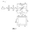
- Photoacoustic sensor 100 comprises an excitation source 110, a modulator 116, a quantum dot filter 118, an interferometer 120, and a gas chamber 130.
- the excitation source 110 may be a laser or an LED, which may generate a monochromatic light 112.
- the modulator 116 may intensity (or amplitude) modulate the monochromatic light 112 at a first modulation frequency f(1) to create a beam of intensity modulated monochromatic light 113.
- the first modulation frequency f(1) is in a range of 0kHz and 10 kHz.
- a power supply of the monochromatic light 112 can be used to modulate the monochromatic light 112.
- the quantum dot filter 118 may down-convert the high-energy intensity modulated monochromatic light 113 into a low-energy broadband spectrum 114 of infrared light, which includes a plurality of wavelength components with distinct wavelengths. Therefore, the resulting broadband spectrum 114 of down-converted light from the quantum dot filter 118 is also modulated at the first modulation frequency f(1) and is output to the interferometer 120.
- the quantum dot filter 118 is selected such that the distinct wavelength ⁇ of wavelength components of the broadband spectrum of infrared light 114 emitted by the quantum dot filter 118 corresponds to an energy absorption band of one of a plurality of target sample gases.
- the quantum dot filter 118 it will be known what particular gases the sensor will be used to detect. Therefore, in selecting the quantum dot filter 118, one only needs to determine unique absorption bands of the particular gases, i.e. absorption bands that are not shared with other gases, and then select a quantum dot filter 118 with similar corresponding emission peaks.
- an interchangeable array of quantum dot filters may be used, in which each quantum dot filter emits a different group of wavelengths corresponding to the absorption peaks of a different group of gases.
- the emission peaks of a quantum dot filter are predominately determined by the sizes and compositions of the quantum dots.
- the interferometer 120 may further intensity modulate the broadband spectrum 114 of infrared light, and then output the further intensity modulated broadband spectrum 115 of infrared light to the gas chamber 130.
- a Michelson interferometer 120 is used to further intensity modulate the broadband spectrum 114 of infrared light.
- the Michelson interferometer 120 may include, for example, an input port 122, an output port 124, a beamsplitter (e.g., semi-transparent mirror) 125, a scanning mirror 126 and another mirror 128.
- the Michelson interferometer 120 may further intensity modulate each wavelength component of the broadband spectrum 114 of infrared light at a distinct second modulation frequency f(2 ⁇ ), which is determined by both distinct wavelength ⁇ of each wavelength component and the scanning speed v of the Michelson interferometer 120.
- Michelson interferometer is illustrated in this embodiment, other types of interferometers, for example, a lamellar grating, can also be used to further intensity modulate each distinct wavelength component of the broadband spectrum 114 of infrared light at a distinct frequency.
- other types of interferometers for example, a lamellar grating, can also be used to further intensity modulate each distinct wavelength component of the broadband spectrum 114 of infrared light at a distinct frequency.
- the gas chamber 130 includes a light transparent wall 132, a gas permeable wall 134 to introduce one or more gases, a measurement volume 135 to store the one or more gases, an outer wall 136, and a microphone 138.
- the gas chamber 130 receives the broadband spectrum 115 of infrared light through the light transparent wall 132, in which the broadband spectrum 115 has a plurality of distinct wavelength components modulated at distinct frequencies.
- the microphone 138 which is coupled to the gas chamber 130, detects pressure changes within the gas chamber 130 to produce an acoustic signal 139, which is representative of the properties of a sample gas stored in the gas chamber to identify the one or more gases and analyze their properties.
- the microphone 138 is sensitive to acoustic signals, and is coupled to detect pressure changes within the gas chamber 130. Pressure changes within gas chamber 130 are caused by gases within the gas chamber 130 absorbing the radiant energy of one or more of the distinct component wavelength 115 and changing temperature as a result. The temperature fluctuations in the gas track modulation frequencies f(2 ⁇ ) of the distinct wavelength components 115. Within chamber 130, pressure fluctuations that accompany the temperature fluctuations are detected by the microphone 138. Any suitable acoustic transducer may be used as the microphone 138. In an embodiment, the microphone 138 may comprise an electronic microphone. In an alternative embodiment, microphone 138 may comprise a piezoelectric material.
- the outer wall 136 of the gas chamber 130 may be constructed of any suitable material.
- the outer wall 136 may comprise a metal, such as aluminum.
- the outer wall 136 may comprise a plastic, or polymer, such as methacrylate.
- the gas permeable wall 134 may be covered by a porous membrane formed of paper, a porous metal, or a gas permeable polymer. Thus, after photoacoustic sensor 100 is located for several minutes within a given environment, the gas mixture within the gas chamber 130 will substantially match the gas mixture of the surrounding environment.
- the wall 134 may also be a valve type of structure that would open and introduce the sample gas into the gas chamber 130 and then close to make the measurement.
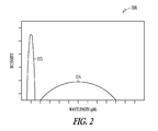
- Figure 2 is a graph 200 illustrating wavelength and intensity of light used by a photoacoustic sensor 100 according to an example embodiment.
- Graph 200 shows, in an example embodiment, that the quantum dot filter 118 down-converts the high-energy intensity modulated monochromatic light 113 into a low-energy broadband spectrum 114 of infrared light (shown on the x-axis, in microns), which includes a plurality of wavelength components with distinct wavelength.
- Graph 200 also shows that the spectrum 114 emitted by the quantum dot filter 118 is within a broad range of wavelengths in the infrared band, and is of a longer wavelength than the modulated monochromatic light 113.
- FIG 3 is a diagram illustrating a photoacoustic gas sensing system 300 according to an example embodiment.
- the photoacoustic gas sensing system 300 comprises an excitation source 110, a modulator 116, a quantum dot filter 118, an interferometer 120, a gas chamber 130 (which has a light transparent wall 132, a gas permeable wall 134, an outer wall 136, and a microphone 138), a temperature sensor 310, a pressure sensor 312, a photodiode 314, a processor 302, a power source 304, a memory 306, and a display 308.
- Elements 110, 116, 118, 120, 130, 132, 134, 136, and 138 may be identical or similar to the elements described in Figure 1 .
- the temperature sensor 310 is coupled to the microphone 138.
- the temperature sensor 310 measures the temperature of the microphone 138 in order to generate a correction signal to compensate for temperature induced changes in sensitivity of the microphone 118. Any suitable temperature measurement device may be used for this purpose.
- the temperature sensor 310 may comprise a thermocouple.
- the pressure sensor 312 is coupled to the gas chamber 130. Pressure sensor 312 measures the atmospheric pressure of the gas chamber 130 in order to generate a pressure correction signal.
- the pressure sensor 312 may be used to compensate for variations in the environment surrounding photoacoustic sensor 100. For example, the pressure sensor 312 may be used to compensate for changes in barometric pressure caused by a change in altitude or weather conditions. Any suitable pressure measurement device may be used for this purpose.
- the photodiode 314 is located between the excitation source 110 and the intensity modulator 116. Photodiode 314 is positioned to measure the intensity of the monochromatic light 112 emitted by the excitation source 110, and may be used for the purpose of calibrating the photoacoustic gas sensing system 300.
- the processor 302 receives signals related to pressure changes within the gas chamber 130.
- the processor 302 is electrically coupled to the excitation source 110 and the microphone 138.
- the processor 302 includes circuitry for controlling the modulation of the excitation source 110, as well as circuitry for receiving and processing signals from the microphone 138, the temperature sensor 310, the pressure sensor 312, and the photodiode 314.
- the processor 302 performs calculations on the signals to identify the one or more gases within the gas chamber 130 and a concentration corresponding to each of those gases.
- the processor 302 may comprise a microcontroller.
- the memory 306 is used by the processor circuitry during operation, and may include random access memory (RAM), one or more hard drives, and/or one or more drives that handle removable media.
- RAM random access memory
- hard drives one or more hard drives
- drives that handle removable media.
- the display 308 indicates the presence and respective concentration values of the particular gases within the gas chamber 130.
- the display 308 may comprise any suitable output device, including a video terminal, LED indicator, analog gauge, printer, or other peripheral device. Generally, the display 308 indicates concentration measures of particular gases in terms of parts per million (ppm).
- the display 308 may also be used to indicate the modulation frequency of excitation source 110.
- the display 308 indicates the concentration value corrected for ambient temperature and pressure.
- the display 308 comprises an indicator lamp or LED that illuminates when the concentration of a particular gas reaches a predetermined level.
- the power source 304 provides power to the excitation source 110, the modulator 116, the microphone 138, the temperature sensor 310, the pressure sensor 312, the processor 302, the memory 306, and the display 308.
- the system 300 is portable, and the power source 304 may comprise a battery, such as a rechargeable lithium-ion battery.
- the power source 304 may comprise an alternating current (AC) adaptor.
- Figure 4 is a flow diagram 400 illustrating a method of detecting gas by a photoacoustic sensor 100 as shown in Figure 1 according to an example embodiment.
- the excitation source 110 for example a laser device or LED, generates a monochromatic light 112, for example a laser.
- the modulator 116 intensity modulates the monochromatic light 112 at a first modulation frequency f(1) to generate a modulated monochromatic light 113.
- the first modulation frequency f(1) is, for example, in a range of kHz and 10 kHz.
- the quantum dot filter 118 down-converts the modulated monochromatic light 113 to a broadband spectrum 114 of infrared light, which includes a plurality of wavelength components with distinct wavelengths. Therefore, the broadband spectrum 114 of the down-converted light emitted from the quantum dot filter 118 is also modulated at the first modulation frequency f(1) and is output to the input port 122 of the interferometer 120.
- the interferometer 120 further intensity modulates the input broadband spectrum 114 of infrared light at a second frequency f(2 ⁇ ), and then output the resultant intensity modulated broadband spectrum 115 of infrared light through the output port 124 of the interferometer 120.
- each wavelength component of the broadband spectrum 114 of infrared light is further intensity modulated at a second modulation frequency f(2 ⁇ ), which is a function of a scanning speed v of the interferometer 120 and a distinct wavelength ⁇ of each wavelength component.
- f(2 ⁇ ) 2v/ ⁇ .
- the gas chamber 130 receives the resultant modulated broadband spectrum 115 of infrared light emitted from the interferometer 120.
- the microphone 138 detects pressure changes within the gas chamber 130 to produce an acoustic signal corresponding to one or more energy absorption of one or more gases contained in the gas chamber. These pressure changes will occur at the resultant frequencies of each wavelength component of the resultant broadband spectrum 115 of infrared light, and will vary in intensity according to the concentration of the one or more gases. Pressure changes are detected and converted to an electrical signal by the microphone 138. A processor may then be used to perform calculations on the electrical signal produced by the microphone 138, which allows for the determination of the presence and concentration of one or more gases. The concentrations of the one or more gases may be displayed, or may be used to trigger an alarm if greater than a predetermined level.
Landscapes
- Physics & Mathematics (AREA)
- Health & Medical Sciences (AREA)
- Life Sciences & Earth Sciences (AREA)
- Chemical & Material Sciences (AREA)
- Analytical Chemistry (AREA)
- Biochemistry (AREA)
- General Health & Medical Sciences (AREA)
- General Physics & Mathematics (AREA)
- Immunology (AREA)
- Pathology (AREA)
- Investigating Or Analysing Materials By Optical Means (AREA)
- Investigating Or Analyzing Materials By The Use Of Ultrasonic Waves (AREA)
Applications Claiming Priority (1)
| Application Number | Priority Date | Filing Date | Title |
|---|---|---|---|
| US12/195,531 US8085403B2 (en) | 2008-08-21 | 2008-08-21 | Photoacoustic sensor |
Publications (2)
| Publication Number | Publication Date |
|---|---|
| EP2157419A1 true EP2157419A1 (de) | 2010-02-24 |
| EP2157419B1 EP2157419B1 (de) | 2010-10-27 |
Family
ID=41346157
Family Applications (1)
| Application Number | Title | Priority Date | Filing Date |
|---|---|---|---|
| EP09168210A Not-in-force EP2157419B1 (de) | 2008-08-21 | 2009-08-19 | Photoakustischer Sensor |
Country Status (4)
| Country | Link |
|---|---|
| US (2) | US8085403B2 (de) |
| EP (1) | EP2157419B1 (de) |
| AT (1) | ATE486274T1 (de) |
| DE (1) | DE602009000309D1 (de) |
Cited By (3)
| Publication number | Priority date | Publication date | Assignee | Title |
|---|---|---|---|---|
| WO2010081739A1 (en) * | 2009-01-16 | 2010-07-22 | Fraunhofer-Gesellschaft zur Förderung der angewandten Forschung e.V. | Photoacoustic gas analyser with interferometric modulation |
| CN113155742A (zh) * | 2021-04-02 | 2021-07-23 | 浙江大学 | 同时检测多种气体的单共振腔光声光谱系统及检测方法 |
| CN116337777A (zh) * | 2023-05-29 | 2023-06-27 | 之江实验室 | 一种基于单光梳的宽频带光声光谱测量系统及方法 |
Families Citing this family (27)
| Publication number | Priority date | Publication date | Assignee | Title |
|---|---|---|---|---|
| US8085403B2 (en) * | 2008-08-21 | 2011-12-27 | Honeywell International Inc. | Photoacoustic sensor |
| BR112013000100A2 (pt) | 2010-07-08 | 2016-05-17 | Halliburton Energy Services Inc | método, e, sistema para determinar a presença de um componente constituinte em um fluido de amostra |
| GB2484673A (en) * | 2010-10-18 | 2012-04-25 | Univ Dublin City | A photoacoustic inspection device |
| US8746038B2 (en) | 2011-04-01 | 2014-06-10 | Honeywell International Inc. | Photoacoustic detector with acoustic and vibration noise compensation |
| US8661874B2 (en) | 2011-04-28 | 2014-03-04 | Honeywell International Inc. | Photoacoustic detector with background signal correction |
| US9086364B2 (en) | 2011-04-28 | 2015-07-21 | Honeywell International Inc. | Photoacoustic sensor with baseline and span correction |
| US8701465B2 (en) | 2011-04-28 | 2014-04-22 | Honeywell International Inc. | Photoacoustic sensor diffusion membrane attachment structure |
| US8939006B2 (en) | 2011-05-04 | 2015-01-27 | Honeywell International Inc. | Photoacoustic detector with long term drift compensation |
| US8689607B2 (en) | 2011-05-04 | 2014-04-08 | Honeywell International Inc. | Apparatus and method of photoacoustic sensor signal acquisition |
| US8594507B2 (en) * | 2011-06-16 | 2013-11-26 | Honeywell International Inc. | Method and apparatus for measuring gas concentrations |
| US8848191B2 (en) | 2012-03-14 | 2014-09-30 | Honeywell International Inc. | Photoacoustic sensor with mirror |
| DE102012008102B3 (de) * | 2012-04-25 | 2013-08-01 | Testo Ag | Messvorrichtung und Messverfahren |
| US20140026639A1 (en) * | 2012-07-30 | 2014-01-30 | General Electric Company | System and method for photoacoustic gas analysis |
| US9410931B1 (en) | 2013-10-17 | 2016-08-09 | Sandia Corporation | Miniaturized photoacoustic spectrometer |
| US9652035B2 (en) * | 2015-02-23 | 2017-05-16 | International Business Machines Corporation | Interfacing via heads-up display using eye contact |
| US10883875B2 (en) | 2015-03-05 | 2021-01-05 | Honeywell International Inc. | Use of selected glass types and glass thicknesses in the optical path to remove cross sensitivity to water absorption peaks |
| CN108351294A (zh) | 2015-09-10 | 2018-07-31 | 霍尼韦尔国际公司 | 具有归一化响应和改进灵敏度的气体检测器 |
| EP3359933A1 (de) | 2015-10-09 | 2018-08-15 | Honeywell International Inc. | Detektor für elektromagnetische strahlung mit einer planaren golay-zelle |
| WO2017073396A1 (ja) * | 2015-10-28 | 2017-05-04 | 東京エレクトロン株式会社 | 基板処理方法、基板処理装置、基板処理システム及び記憶媒体 |
| US10620165B2 (en) * | 2016-12-29 | 2020-04-14 | Infineon Technologies Ag | Photoacoustic gas analyzer for determining species concentrations using intensity modulation |
| CN107802239B (zh) * | 2017-11-16 | 2020-07-31 | 重庆医科大学 | 一种在生物体组织内成像的系统 |
| EP3508836B1 (de) * | 2018-01-05 | 2020-07-29 | Infineon Technologies AG | Photoakustisches system und verfahren zur abschätzung einer gaskonzentration |
| FR3112857B1 (fr) * | 2020-07-21 | 2025-03-07 | Draegerwerk Ag & Co Kgaa | Capteur photoacoustique à gaz de substitution et procédé de détection le mettant en œuvre |
| CN116165146B (zh) * | 2023-02-28 | 2026-04-21 | 西安交通大学 | 一种光声光谱式多气体mems微型气体传感器 |
| CN117629898B (zh) * | 2024-01-25 | 2024-05-07 | 杭州泽天春来科技股份有限公司 | 光声光谱气体分析仪的信号处理方法、系统及可读介质 |
| CN119354361A (zh) * | 2024-12-25 | 2025-01-24 | 山东省科学院激光研究所 | 一种基于二次谐波的干扰消除及温度检测方法、系统 |
| CN119619013B (zh) * | 2025-01-07 | 2026-04-14 | 山西大学 | 一种傅里叶光声气体检测装置及方法 |
Citations (6)
| Publication number | Priority date | Publication date | Assignee | Title |
|---|---|---|---|---|
| US4457162A (en) * | 1982-09-17 | 1984-07-03 | Institute Of Gas Technology | Multi-frequency photo-acoustic detector |
| EP1111367A2 (de) * | 1996-12-31 | 2001-06-27 | Honeywell Inc. | Photoakustische Vorrichtung und Verfahren zur Feststellung mehrerer Gase |
| US6618148B1 (en) * | 2000-02-10 | 2003-09-09 | Southwest Sciences Incorporated | Acoustic resonance frequency locked photoacoustic spectrometer |
| JP2006323410A (ja) * | 2006-07-18 | 2006-11-30 | Japan Science & Technology Agency | 量子ドットによる波長変換素子 |
| US20070221867A1 (en) * | 2006-03-24 | 2007-09-27 | Goldeneye, Inc. | Wavelength conversion chip for use in solid-state lighting and method for making same |
| EP1857789A2 (de) * | 2006-05-15 | 2007-11-21 | X-Rite, Incorporated | Lichtquelle mit Quantenpunktmaterial und Vorrichtung damit |
Family Cites Families (3)
| Publication number | Priority date | Publication date | Assignee | Title |
|---|---|---|---|---|
| FI118548B (fi) * | 2002-09-30 | 2007-12-14 | Noveltech Solutions Ltd | Fotoakustinen detektori |
| US20110052447A1 (en) * | 2008-02-21 | 2011-03-03 | Roy Eric G | Detection System for Detecting and Measuring Metal Ions in an Aqueous Medium |
| US8085403B2 (en) * | 2008-08-21 | 2011-12-27 | Honeywell International Inc. | Photoacoustic sensor |
-
2008
- 2008-08-21 US US12/195,531 patent/US8085403B2/en not_active Expired - Fee Related
-
2009
- 2009-08-19 EP EP09168210A patent/EP2157419B1/de not_active Not-in-force
- 2009-08-19 AT AT09168210T patent/ATE486274T1/de not_active IP Right Cessation
- 2009-08-19 DE DE602009000309T patent/DE602009000309D1/de active Active
-
2011
- 2011-12-06 US US13/312,368 patent/US8451447B2/en not_active Expired - Fee Related
Patent Citations (6)
| Publication number | Priority date | Publication date | Assignee | Title |
|---|---|---|---|---|
| US4457162A (en) * | 1982-09-17 | 1984-07-03 | Institute Of Gas Technology | Multi-frequency photo-acoustic detector |
| EP1111367A2 (de) * | 1996-12-31 | 2001-06-27 | Honeywell Inc. | Photoakustische Vorrichtung und Verfahren zur Feststellung mehrerer Gase |
| US6618148B1 (en) * | 2000-02-10 | 2003-09-09 | Southwest Sciences Incorporated | Acoustic resonance frequency locked photoacoustic spectrometer |
| US20070221867A1 (en) * | 2006-03-24 | 2007-09-27 | Goldeneye, Inc. | Wavelength conversion chip for use in solid-state lighting and method for making same |
| EP1857789A2 (de) * | 2006-05-15 | 2007-11-21 | X-Rite, Incorporated | Lichtquelle mit Quantenpunktmaterial und Vorrichtung damit |
| JP2006323410A (ja) * | 2006-07-18 | 2006-11-30 | Japan Science & Technology Agency | 量子ドットによる波長変換素子 |
Non-Patent Citations (2)
| Title |
|---|
| MARK G ROCKLEY ET AL: "FOURIER-TRANSFORMED INFRARED PHOTOACOUSTIC SPECTROSCOPY, THE TECHNIQUE AND ITS APPLICATIONS", ULTRASONICS SYMPOSIUM. PROCEEDINGS, IEEE, NEW YORK, NY, US, vol. 2, 5 November 1980 (1980-11-05), pages 649 - 651, XP007910674, ISSN: 0090-5607 * |
| SCHILT S ET AL: "Continuous and simultaneous multigas monitoring using a highly sensitive and selective photoacoustic sensor", LASERS AND ELECTRO-OPTICS, 2005. (CLEO). CONFERENCE ON BALTIMORE, MD, USA MAY 22-27, 2005, PISCATAWAY, NJ, USA,IEEE, vol. 2, 22 May 2005 (2005-05-22), pages 1215 - 1217, XP010876779, ISBN: 978-1-55752-795-0 * |
Cited By (4)
| Publication number | Priority date | Publication date | Assignee | Title |
|---|---|---|---|---|
| WO2010081739A1 (en) * | 2009-01-16 | 2010-07-22 | Fraunhofer-Gesellschaft zur Förderung der angewandten Forschung e.V. | Photoacoustic gas analyser with interferometric modulation |
| CN113155742A (zh) * | 2021-04-02 | 2021-07-23 | 浙江大学 | 同时检测多种气体的单共振腔光声光谱系统及检测方法 |
| CN116337777A (zh) * | 2023-05-29 | 2023-06-27 | 之江实验室 | 一种基于单光梳的宽频带光声光谱测量系统及方法 |
| CN116337777B (zh) * | 2023-05-29 | 2023-08-29 | 之江实验室 | 一种基于单光梳的宽频带光声光谱测量系统及方法 |
Also Published As
| Publication number | Publication date |
|---|---|
| DE602009000309D1 (de) | 2010-12-09 |
| EP2157419B1 (de) | 2010-10-27 |
| US8451447B2 (en) | 2013-05-28 |
| US20100045998A1 (en) | 2010-02-25 |
| US20120075618A1 (en) | 2012-03-29 |
| US8085403B2 (en) | 2011-12-27 |
| ATE486274T1 (de) | 2010-11-15 |
Similar Documents
| Publication | Publication Date | Title |
|---|---|---|
| US8085403B2 (en) | Photoacoustic sensor | |
| EP2092306B1 (de) | Probenkonzentrationsdetektor mit temperaturausgleich | |
| CN112313498B (zh) | 用于分析气体样品的便携式光谱装置 | |
| US8594507B2 (en) | Method and apparatus for measuring gas concentrations | |
| US7808640B2 (en) | Photoacoustic spectroscopy system | |
| US7710568B1 (en) | Portable natural gas leak detector | |
| JP6075372B2 (ja) | 物質特性測定装置 | |
| CN104422668B (zh) | 检测流体中的组分的方法和系统 | |
| US10620165B2 (en) | Photoacoustic gas analyzer for determining species concentrations using intensity modulation | |
| CN102680412B (zh) | 利用光声光谱法检测微量水蒸气浓度的方法 | |
| EP3139152A1 (de) | Optischer methandetektor, welcher oberschwingungen des hintergrundsignals zur bestimmung der methankonzentration verwendet | |
| KR100419094B1 (ko) | 기체 식별기 | |
| CN102177423A (zh) | 波长调制光谱方法 | |
| US8289517B2 (en) | Method and device for measuring a photoacoustic signal with computer-assisted evaluation | |
| CN119619066B (zh) | 针对烟囱管道的废气检测方法和装置 | |
| US9006685B2 (en) | Device and method for determining the concentration of fluorophores in a sample | |
| CN113433092B (zh) | 一种激光气体分析系统标定方法、标定装置及标定系统 | |
| US7324192B2 (en) | Test apparatus and method for examining sheet-like components for perforations | |
| US20130229284A1 (en) | Gas safety monitor | |
| US20180202925A1 (en) | Sensor | |
| Maliński et al. | Theoretical and experimental studies of a plasma wave contribution to the photoacoustic signal for Si samples | |
| WO2026013557A1 (en) | Method for active photoacoustic noise cancellation | |
| Ma et al. | Investigation of trace gas sensor based on QEPAS method using different QTFs | |
| Wainner et al. | Tunable diode laser wavelength modulation spectroscopy (TDL-WMS) using a fiber-amplified source | |
| Starecki | Simultaneous photoacoustic detection of multiple compounds based on orthogonal functions stimulation |
Legal Events
| Date | Code | Title | Description |
|---|---|---|---|
| PUAI | Public reference made under article 153(3) epc to a published international application that has entered the european phase |
Free format text: ORIGINAL CODE: 0009012 |
|
| 17P | Request for examination filed |
Effective date: 20090819 |
|
| AK | Designated contracting states |
Kind code of ref document: A1 Designated state(s): AT BE BG CH CY CZ DE DK EE ES FI FR GB GR HR HU IE IS IT LI LT LU LV MC MK MT NL NO PL PT RO SE SI SK SM TR |
|
| AX | Request for extension of the european patent |
Extension state: AL BA RS |
|
| R17C | First examination report despatched (corrected) |
Effective date: 20091228 |
|
| GRAP | Despatch of communication of intention to grant a patent |
Free format text: ORIGINAL CODE: EPIDOSNIGR1 |
|
| GRAC | Information related to communication of intention to grant a patent modified |
Free format text: ORIGINAL CODE: EPIDOSCIGR1 |
|
| GRAS | Grant fee paid |
Free format text: ORIGINAL CODE: EPIDOSNIGR3 |
|
| GRAA | (expected) grant |
Free format text: ORIGINAL CODE: 0009210 |
|
| AK | Designated contracting states |
Kind code of ref document: B1 Designated state(s): AT BE BG CH CY CZ DE DK EE ES FI FR GB GR HR HU IE IS IT LI LT LU LV MC MK MT NL NO PL PT RO SE SI SK SM TR |
|
| REG | Reference to a national code |
Ref country code: GB Ref legal event code: FG4D |
|
| REG | Reference to a national code |
Ref country code: CH Ref legal event code: EP |
|
| REG | Reference to a national code |
Ref country code: IE Ref legal event code: FG4D |
|
| REF | Corresponds to: |
Ref document number: 602009000309 Country of ref document: DE Date of ref document: 20101209 Kind code of ref document: P |
|
| REG | Reference to a national code |
Ref country code: NL Ref legal event code: VDEP Effective date: 20101027 |
|
| LTIE | Lt: invalidation of european patent or patent extension |
Effective date: 20101027 |
|
| PG25 | Lapsed in a contracting state [announced via postgrant information from national office to epo] |
Ref country code: LT Free format text: LAPSE BECAUSE OF FAILURE TO SUBMIT A TRANSLATION OF THE DESCRIPTION OR TO PAY THE FEE WITHIN THE PRESCRIBED TIME-LIMIT Effective date: 20101027 Ref country code: NO Free format text: LAPSE BECAUSE OF FAILURE TO SUBMIT A TRANSLATION OF THE DESCRIPTION OR TO PAY THE FEE WITHIN THE PRESCRIBED TIME-LIMIT Effective date: 20110127 |
|
| PG25 | Lapsed in a contracting state [announced via postgrant information from national office to epo] |
Ref country code: LV Free format text: LAPSE BECAUSE OF FAILURE TO SUBMIT A TRANSLATION OF THE DESCRIPTION OR TO PAY THE FEE WITHIN THE PRESCRIBED TIME-LIMIT Effective date: 20101027 Ref country code: PT Free format text: LAPSE BECAUSE OF FAILURE TO SUBMIT A TRANSLATION OF THE DESCRIPTION OR TO PAY THE FEE WITHIN THE PRESCRIBED TIME-LIMIT Effective date: 20110228 Ref country code: BG Free format text: LAPSE BECAUSE OF FAILURE TO SUBMIT A TRANSLATION OF THE DESCRIPTION OR TO PAY THE FEE WITHIN THE PRESCRIBED TIME-LIMIT Effective date: 20110127 Ref country code: SE Free format text: LAPSE BECAUSE OF FAILURE TO SUBMIT A TRANSLATION OF THE DESCRIPTION OR TO PAY THE FEE WITHIN THE PRESCRIBED TIME-LIMIT Effective date: 20101027 Ref country code: NL Free format text: LAPSE BECAUSE OF FAILURE TO SUBMIT A TRANSLATION OF THE DESCRIPTION OR TO PAY THE FEE WITHIN THE PRESCRIBED TIME-LIMIT Effective date: 20101027 Ref country code: FI Free format text: LAPSE BECAUSE OF FAILURE TO SUBMIT A TRANSLATION OF THE DESCRIPTION OR TO PAY THE FEE WITHIN THE PRESCRIBED TIME-LIMIT Effective date: 20101027 Ref country code: IS Free format text: LAPSE BECAUSE OF FAILURE TO SUBMIT A TRANSLATION OF THE DESCRIPTION OR TO PAY THE FEE WITHIN THE PRESCRIBED TIME-LIMIT Effective date: 20110227 Ref country code: HR Free format text: LAPSE BECAUSE OF FAILURE TO SUBMIT A TRANSLATION OF THE DESCRIPTION OR TO PAY THE FEE WITHIN THE PRESCRIBED TIME-LIMIT Effective date: 20101027 Ref country code: SI Free format text: LAPSE BECAUSE OF FAILURE TO SUBMIT A TRANSLATION OF THE DESCRIPTION OR TO PAY THE FEE WITHIN THE PRESCRIBED TIME-LIMIT Effective date: 20101027 Ref country code: AT Free format text: LAPSE BECAUSE OF FAILURE TO SUBMIT A TRANSLATION OF THE DESCRIPTION OR TO PAY THE FEE WITHIN THE PRESCRIBED TIME-LIMIT Effective date: 20101027 |
|
| PG25 | Lapsed in a contracting state [announced via postgrant information from national office to epo] |
Ref country code: BE Free format text: LAPSE BECAUSE OF FAILURE TO SUBMIT A TRANSLATION OF THE DESCRIPTION OR TO PAY THE FEE WITHIN THE PRESCRIBED TIME-LIMIT Effective date: 20101027 Ref country code: GR Free format text: LAPSE BECAUSE OF FAILURE TO SUBMIT A TRANSLATION OF THE DESCRIPTION OR TO PAY THE FEE WITHIN THE PRESCRIBED TIME-LIMIT Effective date: 20110128 |
|
| PG25 | Lapsed in a contracting state [announced via postgrant information from national office to epo] |
Ref country code: ES Free format text: LAPSE BECAUSE OF FAILURE TO SUBMIT A TRANSLATION OF THE DESCRIPTION OR TO PAY THE FEE WITHIN THE PRESCRIBED TIME-LIMIT Effective date: 20110207 Ref country code: EE Free format text: LAPSE BECAUSE OF FAILURE TO SUBMIT A TRANSLATION OF THE DESCRIPTION OR TO PAY THE FEE WITHIN THE PRESCRIBED TIME-LIMIT Effective date: 20101027 Ref country code: CZ Free format text: LAPSE BECAUSE OF FAILURE TO SUBMIT A TRANSLATION OF THE DESCRIPTION OR TO PAY THE FEE WITHIN THE PRESCRIBED TIME-LIMIT Effective date: 20101027 |
|
| PG25 | Lapsed in a contracting state [announced via postgrant information from national office to epo] |
Ref country code: SK Free format text: LAPSE BECAUSE OF FAILURE TO SUBMIT A TRANSLATION OF THE DESCRIPTION OR TO PAY THE FEE WITHIN THE PRESCRIBED TIME-LIMIT Effective date: 20101027 Ref country code: PL Free format text: LAPSE BECAUSE OF FAILURE TO SUBMIT A TRANSLATION OF THE DESCRIPTION OR TO PAY THE FEE WITHIN THE PRESCRIBED TIME-LIMIT Effective date: 20101027 Ref country code: DK Free format text: LAPSE BECAUSE OF FAILURE TO SUBMIT A TRANSLATION OF THE DESCRIPTION OR TO PAY THE FEE WITHIN THE PRESCRIBED TIME-LIMIT Effective date: 20101027 Ref country code: RO Free format text: LAPSE BECAUSE OF FAILURE TO SUBMIT A TRANSLATION OF THE DESCRIPTION OR TO PAY THE FEE WITHIN THE PRESCRIBED TIME-LIMIT Effective date: 20101027 |
|
| PLBE | No opposition filed within time limit |
Free format text: ORIGINAL CODE: 0009261 |
|
| STAA | Information on the status of an ep patent application or granted ep patent |
Free format text: STATUS: NO OPPOSITION FILED WITHIN TIME LIMIT |
|
| 26N | No opposition filed |
Effective date: 20110728 |
|
| REG | Reference to a national code |
Ref country code: DE Ref legal event code: R097 Ref document number: 602009000309 Country of ref document: DE Effective date: 20110728 |
|
| PG25 | Lapsed in a contracting state [announced via postgrant information from national office to epo] |
Ref country code: MT Free format text: LAPSE BECAUSE OF FAILURE TO SUBMIT A TRANSLATION OF THE DESCRIPTION OR TO PAY THE FEE WITHIN THE PRESCRIBED TIME-LIMIT Effective date: 20101027 Ref country code: IT Free format text: LAPSE BECAUSE OF FAILURE TO SUBMIT A TRANSLATION OF THE DESCRIPTION OR TO PAY THE FEE WITHIN THE PRESCRIBED TIME-LIMIT Effective date: 20101027 |
|
| PG25 | Lapsed in a contracting state [announced via postgrant information from national office to epo] |
Ref country code: MC Free format text: LAPSE BECAUSE OF NON-PAYMENT OF DUE FEES Effective date: 20110831 |
|
| REG | Reference to a national code |
Ref country code: FR Ref legal event code: ST Effective date: 20120430 |
|
| REG | Reference to a national code |
Ref country code: IE Ref legal event code: MM4A |
|
| PG25 | Lapsed in a contracting state [announced via postgrant information from national office to epo] |
Ref country code: IE Free format text: LAPSE BECAUSE OF NON-PAYMENT OF DUE FEES Effective date: 20110819 |
|
| PG25 | Lapsed in a contracting state [announced via postgrant information from national office to epo] |
Ref country code: FR Free format text: LAPSE BECAUSE OF NON-PAYMENT OF DUE FEES Effective date: 20110831 |
|
| PG25 | Lapsed in a contracting state [announced via postgrant information from national office to epo] |
Ref country code: MK Free format text: LAPSE BECAUSE OF FAILURE TO SUBMIT A TRANSLATION OF THE DESCRIPTION OR TO PAY THE FEE WITHIN THE PRESCRIBED TIME-LIMIT Effective date: 20101027 |
|
| PG25 | Lapsed in a contracting state [announced via postgrant information from national office to epo] |
Ref country code: SM Free format text: LAPSE BECAUSE OF FAILURE TO SUBMIT A TRANSLATION OF THE DESCRIPTION OR TO PAY THE FEE WITHIN THE PRESCRIBED TIME-LIMIT Effective date: 20101027 |
|
| PG25 | Lapsed in a contracting state [announced via postgrant information from national office to epo] |
Ref country code: CY Free format text: LAPSE BECAUSE OF EXPIRATION OF PROTECTION Effective date: 20101027 Ref country code: LU Free format text: LAPSE BECAUSE OF NON-PAYMENT OF DUE FEES Effective date: 20110819 |
|
| PG25 | Lapsed in a contracting state [announced via postgrant information from national office to epo] |
Ref country code: TR Free format text: LAPSE BECAUSE OF FAILURE TO SUBMIT A TRANSLATION OF THE DESCRIPTION OR TO PAY THE FEE WITHIN THE PRESCRIBED TIME-LIMIT Effective date: 20101027 |
|
| PG25 | Lapsed in a contracting state [announced via postgrant information from national office to epo] |
Ref country code: HU Free format text: LAPSE BECAUSE OF FAILURE TO SUBMIT A TRANSLATION OF THE DESCRIPTION OR TO PAY THE FEE WITHIN THE PRESCRIBED TIME-LIMIT Effective date: 20101027 |
|
| REG | Reference to a national code |
Ref country code: CH Ref legal event code: PL |
|
| PG25 | Lapsed in a contracting state [announced via postgrant information from national office to epo] |
Ref country code: LI Free format text: LAPSE BECAUSE OF NON-PAYMENT OF DUE FEES Effective date: 20130831 Ref country code: CH Free format text: LAPSE BECAUSE OF NON-PAYMENT OF DUE FEES Effective date: 20130831 |
|
| PGFP | Annual fee paid to national office [announced via postgrant information from national office to epo] |
Ref country code: DE Payment date: 20150831 Year of fee payment: 7 Ref country code: GB Payment date: 20150728 Year of fee payment: 7 |
|
| REG | Reference to a national code |
Ref country code: DE Ref legal event code: R119 Ref document number: 602009000309 Country of ref document: DE |
|
| GBPC | Gb: european patent ceased through non-payment of renewal fee |
Effective date: 20160819 |
|
| PG25 | Lapsed in a contracting state [announced via postgrant information from national office to epo] |
Ref country code: GB Free format text: LAPSE BECAUSE OF NON-PAYMENT OF DUE FEES Effective date: 20160819 Ref country code: DE Free format text: LAPSE BECAUSE OF NON-PAYMENT OF DUE FEES Effective date: 20170301 |