EP2157443A1 - Radar haute fréquence à onde de surface - Google Patents
Radar haute fréquence à onde de surface Download PDFInfo
- Publication number
- EP2157443A1 EP2157443A1 EP08252791A EP08252791A EP2157443A1 EP 2157443 A1 EP2157443 A1 EP 2157443A1 EP 08252791 A EP08252791 A EP 08252791A EP 08252791 A EP08252791 A EP 08252791A EP 2157443 A1 EP2157443 A1 EP 2157443A1
- Authority
- EP
- European Patent Office
- Prior art keywords
- antenna
- antenna element
- frequency
- range
- transmit
- Prior art date
- Legal status (The legal status is an assumption and is not a legal conclusion. Google has not performed a legal analysis and makes no representation as to the accuracy of the status listed.)
- Ceased
Links
- 238000009434 installation Methods 0.000 claims abstract description 29
- 230000005540 biological transmission Effects 0.000 claims description 20
- 230000008054 signal transmission Effects 0.000 description 2
- 230000003466 anti-cipated effect Effects 0.000 description 1
- 238000001514 detection method Methods 0.000 description 1
- 230000007613 environmental effect Effects 0.000 description 1
- 238000012423 maintenance Methods 0.000 description 1
- 239000000463 material Substances 0.000 description 1
- 238000012544 monitoring process Methods 0.000 description 1
- 230000005404 monopole Effects 0.000 description 1
- 230000002787 reinforcement Effects 0.000 description 1
- 239000007787 solid Substances 0.000 description 1
Images
Classifications
-
- H—ELECTRICITY
- H01—ELECTRIC ELEMENTS
- H01Q—ANTENNAS, i.e. RADIO AERIALS
- H01Q21/00—Antenna arrays or systems
- H01Q21/28—Combinations of substantially independent non-interacting antenna units or systems
-
- G—PHYSICS
- G01—MEASURING; TESTING
- G01S—RADIO DIRECTION-FINDING; RADIO NAVIGATION; DETERMINING DISTANCE OR VELOCITY BY USE OF RADIO WAVES; LOCATING OR PRESENCE-DETECTING BY USE OF THE REFLECTION OR RERADIATION OF RADIO WAVES; ANALOGOUS ARRANGEMENTS USING OTHER WAVES
- G01S13/00—Systems using the reflection or reradiation of radio waves, e.g. radar systems; Analogous systems using reflection or reradiation of waves whose nature or wavelength is irrelevant or unspecified
- G01S13/02—Systems using reflection of radio waves, e.g. primary radar systems; Analogous systems
- G01S13/0218—Very long range radars, e.g. surface wave radar, over-the-horizon or ionospheric propagation systems
-
- G—PHYSICS
- G01—MEASURING; TESTING
- G01S—RADIO DIRECTION-FINDING; RADIO NAVIGATION; DETERMINING DISTANCE OR VELOCITY BY USE OF RADIO WAVES; LOCATING OR PRESENCE-DETECTING BY USE OF THE REFLECTION OR RERADIATION OF RADIO WAVES; ANALOGOUS ARRANGEMENTS USING OTHER WAVES
- G01S7/00—Details of systems according to groups G01S13/00, G01S15/00, G01S17/00
- G01S7/02—Details of systems according to groups G01S13/00, G01S15/00, G01S17/00 of systems according to group G01S13/00
- G01S7/03—Details of HF subsystems specially adapted therefor, e.g. common to transmitter and receiver
-
- H—ELECTRICITY
- H01—ELECTRIC ELEMENTS
- H01Q—ANTENNAS, i.e. RADIO AERIALS
- H01Q19/00—Combinations of primary active antenna elements and units with secondary devices, e.g. with quasi-optical devices, for giving the antenna a desired directional characteristic
- H01Q19/28—Combinations of primary active antenna elements and units with secondary devices, e.g. with quasi-optical devices, for giving the antenna a desired directional characteristic using a secondary device in the form of two or more substantially straight conductive elements
- H01Q19/30—Combinations of primary active antenna elements and units with secondary devices, e.g. with quasi-optical devices, for giving the antenna a desired directional characteristic using a secondary device in the form of two or more substantially straight conductive elements the primary active element being centre-fed and substantially straight, e.g. Yagi antenna
-
- H—ELECTRICITY
- H01—ELECTRIC ELEMENTS
- H01Q—ANTENNAS, i.e. RADIO AERIALS
- H01Q9/00—Electrically-short antennas having dimensions not more than twice the operating wavelength and consisting of conductive active radiating elements
- H01Q9/04—Resonant antennas
- H01Q9/16—Resonant antennas with feed intermediate between the extremities of the antenna, e.g. centre-fed dipole
- H01Q9/28—Conical, cylindrical, cage, strip, gauze, or like elements having an extended radiating surface; Elements comprising two conical surfaces having collinear axes and adjacent apices and fed by two-conductor transmission lines
Definitions
- the present invention relates to a high frequency surfacewave radar (HFSWR) installation.
- HFSWR high frequency surfacewave radar
- Conventional HFSWR transmits an RF signal at a single frequency and detects energy which is returned from objects in the path of the transmitted RF signal.
- the range of HFSWR is significantly enhanced over standard ground - based radar in that the range to a surface target that might be detected is in the order of hundreds of kilometres.
- the frequency range associated with high frequency radar is approximately 3-30 MHz and the corresponding wavelength of the transmitted signal is measured in tens of meters, say 10m to 100m.
- the wavelength of the signal to be transmitted directly governs the size of an associated transmitting antenna element. The magnitude of a HFSWR installation comprising a number of such antenna elements in an array can therefore be significant.
- HFSWR single frequency HFSWR are limited in their performance due to external influences such as man made interference, for example radio transmissions. Consequently, such HFSWR are considered to be “external noise” limited as these external signals dominate any internal noise levels of the internal mechanism such as receive electronics of the radar installation.
- Alternative radar, such as those operating at microwave frequencies, are typically “internal noise” limited as the noise generated by the internal mechanism of the radar dominate any external noise signals at microwave frequencies.
- the present invention provides a high frequency surfacewave radar installation comprising an array of antenna elements, the array comprising:
- the first antenna element may be a doublet capable of directional transmission and/or reception and the second antenna element may be a single dipole capable of omnidirectional transmission and/or reception.
- the overall magnitude of the antenna installation may be optimised.
- the first antenna element may be configured to transmit a signal having a frequency in the range of a first octave and the second antenna element may be configured to transmit a signal having a frequency in the range of a second octave.
- the first and second antenna elements may be doublets capable of directional transmission and/or reception and the array may comprise a third antenna element, wherein the third element may be a single dipole capable of omnidirectional transmission and/or reception. Provision of one or more antenna elements having a single dipole configuration, the overall magnitude of an antenna installation having an extended band width may be optimised.
- the present invention provides a high frequency surfacewave radar installation comprising an array of antenna elements, the array comprising:
- first and second antenna elements each having capability for transmitting in different octaves of frequency
- a compact antenna installation having an extended bandwidth can be achieved.
- the second antenna element may be smaller than the first antenna element.
- the first octave may represent a range of up to 8 MHz and the second octave may represent a range from 8 to 16 MHz.
- the array may comprise a third antenna element configured to transmit a signal having a frequency in the range of a third octave.
- the third antenna element may be smaller than the second antenna element and the third octave may represent a range above 16 MHz.
- the antenna elements may be configured to receive a signal on any frequency covered by the transmission from the radar installation.
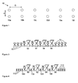
- the antenna 10 illustrated in Figure 1 comprises an array of antenna elements 15a, 15b, 15c, 15d, 15e, 15f.
- each element is represented by a doublet.
- Each doublet comprises a pair of tetrahedral dipoles in a conventional manner.
- the phase relationship between the two dipoles reinforces forward transmission of a signal whilst reducing backward transmission of the signal hence providing directionality of the antenna element.
- the extent of this reinforcement is denoted by the 'front to back ratio' of a particular doublet configuration and the configuration is chosen to achieve a particular result. In this embodiment, the front to back ratio is approximately 15 dB.
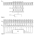
- FIG 2 illustrates a schematic representation of an example antenna 20.
- the antenna 20 comprises an array of sixteen elements, up to six of which, hereinafter referred to as transmitting elements 25a-25f, may be used when the antenna 20 is transmitting as illustrated in Figure 2a and all of which may be used when the antenna 20 is receiving as illustrated in Figure 2b .
- the six transmit elements 25a-25f are each capable of transmission and reception using duplexer units which comprise both a transmission port and a receive port.
- the transmit elements each comprise a doublet and has associated therewith a digital waveform generator 30 and an amplifier 35.
- the amplifier is a 1 kW solid state power amplifier.
- a controller 40 is provided to supply instructions to the waveform generator 30, the amplifier 35 and the antenna 20.
- transmit elements 25a-25f may all be used in combination to transmit an outgoing signal or, alternatively a reduced number, even a single element, may be used to transmit the outgoing signal.
- the number and configuration of elements used to transmit affects the form of signal generated thereby.
- a focused beam having high gain is output in a plane normal to the plane of the array.
- a wider beam, of lower gain can be achieved by using a single element to output the transmission signal.
- Phase ramps or weighting can be implemented across the array in order to achieve an electronic beam steering capability.
- a single frequency can be transmitted by any particular element.
- multiple carrier frequencies can be generated within the waveform to enable more than one frequency to be transmitted by the, or each, element at any one time.
- Transmit signals are generated by the digital waveform generator 30 associated with each element.
- the waveform generators are fully controlled by software.
- the software replicates analogue production of one or more signals and generates parallel streams of data having multiple frequency content. Such a signal represents a number of independent signals, each having a different transmission frequency.
- the waveform characteristics for each element are independent, fully programmable and arbitrary. In other words, the generation of simultaneous, multiple frequency and beam combinations is enabled on transmission from the antenna 20.
- FIG. 2b illustrates operation of antenna 20 in a receive mode.
- the antenna 20 comprises a plurality of elements 42a-42j in addition to the aforementioned transmit elements 25a-25f.
- Each element 25a-25f, 42a-42j is capable of receiving incoming signals.
- each element 25a-25f, 42a-42j is provided with its own dedicated receiver 45, capable of simultaneous receipt and detection of signals having up to four frequencies.
- the receiver is configured to receive the incoming signal which, as described above, may have multiple frequency content.
- This incoming signal is then digitised and discretised into the separate detected independent signals and passed to controller 40 for signal processing.
- the processing required to perform this discretisation relies on the knowledge that four particular distinct signals are being received on four known frequencies.
- simultaneous receive beam forming is used across the entire array so that electronic beam steering may be used to detect targets in particular directions.
- One element say doublet 42a, is configured with reverse phasing to act as a Rear Lobe Blanking (RLB) antenna.
- Another of the elements 42j serves as an environmental monitoring antenna in addition to being part of the antenna array 20.
- each antenna element is provided by a doublet, i.e. a pair of cooperating dipoles.
- doublets In using doublets exclusively the size and cost of the antenna array 20 may become significant. It is desirable to reduce the complexity and magnitude of the array.
- those antenna elements used solely for receiving signals, elements 42b-42j may comprise single dipoles rather than doublets. In so doing, the number of components in each antenna element is halved thus reducing the material costs, the installation costs and maintenance associated therewith.
- the functionality of the antenna 10 is further expanded.
- Conventional radar operate in a relatively narrow frequency band.
- the apparatus described in the aforementioned embodiment is substantially independent of the operating frequency except in terms of the geometry presented by each antenna element. In particular, it is the height of the dipole that determines the frequency that can be transmitted therefrom.
- Each tetrahedral dipole forming the antenna array 20 for the first embodiment stands approximately 8m high.
- the distance, d, between each tetrahedral dipole of a doublet is approximately 6m [ ⁇ /4].
- the distance, D, between adjacent doublets is approximately ⁇ /2 [10-12m] thus the antenna array 20 is approximately 200 m long. This magnitude of array is required in order to achieve a spacing through which signals can be received and processed to yield quantifiable data.
- the tetrahedral dipole configuration exhibits a greater frequency range than say a conventional monopole or dipole, the range is still limited to a single octave, for example 8-16 MHz.
- the duplexer unit associated with each doublet leads to some inherent restrictions in the device, however the primary restriction of the device is in the physical dimensions, particularly the height, of the dipole itself.
- dipoles having a different physical magnitude may be introduced into the antenna array. To achieve a higher frequency, a smaller sized dipole may be provided.
- Figure 3 illustrates how dipoles (or other antenna elements) of two different sizes can be interlaced with one another in order to achieve two octaves of coverage.
- each element 50 to 56 and 60 to 66 is used for transmission and reception whilst the remainder of the elements 70 are used only to receive signals. As illustrated, each element is provided by a doublet.
- the larger elements 50, 52, 54, 56 transmit on lower frequencies F1, F2, F3, F4, say in the range from 4-8 MHz. Meanwhile, the smaller elements 60, 62, 64, 66 transmit at frequencies F5, F6, F7, F8 in a higher frequency range, say in the range 8-16 MHz.
- Antenna elements having an active tuning capability can be used in place of elements having a different physical magnitude. Such elements are particularly effective on receive where efficiency is less critical.
- three sizes of dipole could be interspersed with one another in order to achieve an installation covering three octaves.
- twelve antenna elements 80 to 86, 90 to 96 and 100 to 106 are used for transmission and reception whilst the remainder of the elements 110 are only used to receive signals.
- the larger elements 80, 82, 84, 86 transmit on lower frequencies F1, F2, F3, F4, say in the range from 4-8 MHz.
- the medium sized elements 90, 92, 94, 96 transmit at frequencies F5, F6, F7, F8 in a higher frequency range, say 8-16MHz.
- the smallest elements 100, 102, 104, 106 transmit at the highest end of the "high frequency" band, say in the range 16-30MHz.
- aircraft targets could be located anywhere and so the directionality afforded by the doublet arrangement is required.
- higher frequencies are required and so the physical magnitude of each dipole is reduced.
- the antennae discussed above each represent a monostatic architecture, whereby the transmit antenna and the receive antenna collocated.
- the aforementioned principals can readily be applied to a bistatic architecture, whereby the transmit antenna is located remotely from the receive antenna, or in a multistatic architecture where one or more remotely located additional antennae are provided.
Landscapes
- Engineering & Computer Science (AREA)
- Radar, Positioning & Navigation (AREA)
- Remote Sensing (AREA)
- Computer Networks & Wireless Communication (AREA)
- Physics & Mathematics (AREA)
- General Physics & Mathematics (AREA)
- Variable-Direction Aerials And Aerial Arrays (AREA)
Priority Applications (4)
| Application Number | Priority Date | Filing Date | Title |
|---|---|---|---|
| EP08252791A EP2157443A1 (fr) | 2008-08-20 | 2008-08-20 | Radar haute fréquence à onde de surface |
| EP09807959A EP2329290A1 (fr) | 2008-08-20 | 2009-08-20 | Radar haute fréquence à ondes de surface |
| AU2009283967A AU2009283967A1 (en) | 2008-08-20 | 2009-08-20 | High frequency surfacewave radar |
| PCT/GB2009/051038 WO2010020813A1 (fr) | 2008-08-20 | 2009-08-20 | Radar haute fréquence à ondes de surface |
Applications Claiming Priority (1)
| Application Number | Priority Date | Filing Date | Title |
|---|---|---|---|
| EP08252791A EP2157443A1 (fr) | 2008-08-20 | 2008-08-20 | Radar haute fréquence à onde de surface |
Publications (1)
| Publication Number | Publication Date |
|---|---|
| EP2157443A1 true EP2157443A1 (fr) | 2010-02-24 |
Family
ID=40677806
Family Applications (1)
| Application Number | Title | Priority Date | Filing Date |
|---|---|---|---|
| EP08252791A Ceased EP2157443A1 (fr) | 2008-08-20 | 2008-08-20 | Radar haute fréquence à onde de surface |
Country Status (1)
| Country | Link |
|---|---|
| EP (1) | EP2157443A1 (fr) |
Citations (6)
| Publication number | Priority date | Publication date | Assignee | Title |
|---|---|---|---|---|
| US2825900A (en) * | 1950-02-17 | 1958-03-04 | Rand Corp | Directional receiver |
| US5293176A (en) * | 1991-11-18 | 1994-03-08 | Apti, Inc. | Folded cross grid dipole antenna element |
| US5418544A (en) * | 1993-04-16 | 1995-05-23 | Apti, Inc. | Stacked crossed grid dipole antenna array element |
| US20030142011A1 (en) * | 2001-11-12 | 2003-07-31 | Telstra Corporation Limited | Surface wave radar |
| US20040066345A1 (en) * | 2002-10-04 | 2004-04-08 | Schadler John L. | Crossed bow tie slot antenna |
| US6933878B1 (en) * | 1984-11-24 | 2005-08-23 | Bae Systems Electronics Limited | Wide bandwidth radar |
-
2008
- 2008-08-20 EP EP08252791A patent/EP2157443A1/fr not_active Ceased
Patent Citations (6)
| Publication number | Priority date | Publication date | Assignee | Title |
|---|---|---|---|---|
| US2825900A (en) * | 1950-02-17 | 1958-03-04 | Rand Corp | Directional receiver |
| US6933878B1 (en) * | 1984-11-24 | 2005-08-23 | Bae Systems Electronics Limited | Wide bandwidth radar |
| US5293176A (en) * | 1991-11-18 | 1994-03-08 | Apti, Inc. | Folded cross grid dipole antenna element |
| US5418544A (en) * | 1993-04-16 | 1995-05-23 | Apti, Inc. | Stacked crossed grid dipole antenna array element |
| US20030142011A1 (en) * | 2001-11-12 | 2003-07-31 | Telstra Corporation Limited | Surface wave radar |
| US20040066345A1 (en) * | 2002-10-04 | 2004-04-08 | Schadler John L. | Crossed bow tie slot antenna |
Non-Patent Citations (2)
| Title |
|---|
| KING R W P: "Surface-wave radar and its application", IEEE TRANSACTIONS ON ANTENNAS AND PROPAGATION, IEEE SERVICE CENTER, PISCATAWAY, NJ, US, vol. 51, no. 10, 1 October 2003 (2003-10-01), pages 3000 - 3002, XP011102125, ISSN: 0018-926X * |
| MONEY D G ET AL: "HF SURFACE WAVE RADAR MANAGEMENT TECHNIQUES APPLIED TO SURFACE CRAFT DETECTION", THE RECORD OF THE IEEE 2000 INTERNATIONAL RADAR CONFERENCE. ALEXANDRIA, VA, MAY 7-12, 2000; [IEEE RADAR CONFERENCE], NEW YORK, NY : IEEE, US, 7 May 2000 (2000-05-07), pages 110 - 115, XP001175444, ISBN: 978-0-7803-5777-8 * |
Similar Documents
| Publication | Publication Date | Title |
|---|---|---|
| WO2010020813A1 (fr) | Radar haute fréquence à ondes de surface | |
| EP2556385B2 (fr) | Système de mesure de compteur électronique | |
| US7737879B2 (en) | Split aperture array for increased short range target coverage | |
| US7423578B1 (en) | Split aperture array for increased short range target coverage | |
| KR100871432B1 (ko) | 저고도 레이더 안테나 | |
| JP3393204B2 (ja) | マルチビームレーダ装置 | |
| US20130088393A1 (en) | Transmit and receive phased array for automotive radar improvement | |
| CN111352081B (zh) | 用于高分辨率雷达系统的行波成像歧管 | |
| GB2443456A (en) | MIMO radar system | |
| JP7098732B2 (ja) | レーダシステム | |
| Moore | UK airborne AESA radar research | |
| CN201673998U (zh) | 行波式多波束圆极化天线 | |
| EP2157443A1 (fr) | Radar haute fréquence à onde de surface | |
| JP4371124B2 (ja) | アンテナ装置 | |
| KR101007213B1 (ko) | 레이더 시스템에서 다수의 복사패턴 형성이 가능한 안테나 결합기 | |
| CN119199760A (zh) | 一种多波束接收窄波束发射的相控阵雷达干扰机系统 | |
| WO1986007467A1 (fr) | Radar de surveillance a faisceaux multiples | |
| Adrian | From AESA radar to digital radar for surface-based applications | |
| EP3780274A1 (fr) | Agencement d'antenne réseau | |
| RU2794466C1 (ru) | Способ обзора воздушного пространства импульсно-доплеровской радиолокационной станцией с активной фазированной антенной решеткой | |
| Adrian | From AESA radar to digital radar for surface applications | |
| Kjellén | Realisation study of digital radar array (DRA) | |
| WO2019138037A1 (fr) | Systèmes radar | |
| IL204908A (en) | Electronic Response System |
Legal Events
| Date | Code | Title | Description |
|---|---|---|---|
| PUAI | Public reference made under article 153(3) epc to a published international application that has entered the european phase |
Free format text: ORIGINAL CODE: 0009012 |
|
| AK | Designated contracting states |
Kind code of ref document: A1 Designated state(s): AT BE BG CH CY CZ DE DK EE ES FI FR GB GR HR HU IE IS IT LI LT LU LV MC MT NL NO PL PT RO SE SI SK TR |
|
| AX | Request for extension of the european patent |
Extension state: AL BA MK RS |
|
| STAA | Information on the status of an ep patent application or granted ep patent |
Free format text: STATUS: THE APPLICATION HAS BEEN REFUSED |
|
| 18R | Application refused |
Effective date: 20091222 |