EP2157456A1 - Plaque réfléchissant la lumière, procédé de fabrication de celle-ci, et dispositif réfléchissant la lumière - Google Patents
Plaque réfléchissant la lumière, procédé de fabrication de celle-ci, et dispositif réfléchissant la lumière Download PDFInfo
- Publication number
- EP2157456A1 EP2157456A1 EP08764724A EP08764724A EP2157456A1 EP 2157456 A1 EP2157456 A1 EP 2157456A1 EP 08764724 A EP08764724 A EP 08764724A EP 08764724 A EP08764724 A EP 08764724A EP 2157456 A1 EP2157456 A1 EP 2157456A1
- Authority
- EP
- European Patent Office
- Prior art keywords
- resin
- light reflecting
- silver
- reflecting plate
- film
- Prior art date
- Legal status (The legal status is an assumption and is not a legal conclusion. Google has not performed a legal analysis and makes no representation as to the accuracy of the status listed.)
- Ceased
Links
Images


Classifications
-
- G—PHYSICS
- G02—OPTICS
- G02B—OPTICAL ELEMENTS, SYSTEMS OR APPARATUS
- G02B5/00—Optical elements other than lenses
- G02B5/08—Mirrors
-
- C—CHEMISTRY; METALLURGY
- C23—COATING METALLIC MATERIAL; COATING MATERIAL WITH METALLIC MATERIAL; CHEMICAL SURFACE TREATMENT; DIFFUSION TREATMENT OF METALLIC MATERIAL; COATING BY VACUUM EVAPORATION, BY SPUTTERING, BY ION IMPLANTATION OR BY CHEMICAL VAPOUR DEPOSITION, IN GENERAL; INHIBITING CORROSION OF METALLIC MATERIAL OR INCRUSTATION IN GENERAL
- C23C—COATING METALLIC MATERIAL; COATING MATERIAL WITH METALLIC MATERIAL; SURFACE TREATMENT OF METALLIC MATERIAL BY DIFFUSION INTO THE SURFACE, BY CHEMICAL CONVERSION OR SUBSTITUTION; COATING BY VACUUM EVAPORATION, BY SPUTTERING, BY ION IMPLANTATION OR BY CHEMICAL VAPOUR DEPOSITION, IN GENERAL
- C23C18/00—Chemical coating by decomposition of either liquid compounds or solutions of the coating forming compounds, without leaving reaction products of surface material in the coating; Contact plating
- C23C18/16—Chemical coating by decomposition of either liquid compounds or solutions of the coating forming compounds, without leaving reaction products of surface material in the coating; Contact plating by reduction or substitution, e.g. electroless plating
- C23C18/31—Coating with metals
- C23C18/42—Coating with noble metals
-
- G—PHYSICS
- G02—OPTICS
- G02B—OPTICAL ELEMENTS, SYSTEMS OR APPARATUS
- G02B6/00—Light guides; Structural details of arrangements comprising light guides and other optical elements, e.g. couplings
- G02B6/0001—Light guides; Structural details of arrangements comprising light guides and other optical elements, e.g. couplings specially adapted for lighting devices or systems
- G02B6/0011—Light guides; Structural details of arrangements comprising light guides and other optical elements, e.g. couplings specially adapted for lighting devices or systems the light guides being planar or of plate-like form
- G02B6/0033—Means for improving the coupling-out of light from the light guide
- G02B6/005—Means for improving the coupling-out of light from the light guide provided by one optical element, or plurality thereof, placed on the light output side of the light guide
- G02B6/0055—Reflecting element, sheet or layer
Definitions
- the present invention relates to a light reflecting plate, a method of manufacturing the same, and a light reflecting device using a light reflecting plate, more particularly to a light reflecting plate with excellent light reflection characteristics, a method of manufacturing the same, and a light reflecting device such as a mirror duct in which a light reflecting plate is provided on the inner wall of a light guiding section and which introduces sunlight to indoor by the light reflecting plate to illuminate the indoor, an illumination fixture equipped with a light reflecting plate of a light source, a liquid crystal display device equipped with a light reflecting plate of external incident light, an edge-lighting type backlight of a liquid crystal display device equipped with the light reflecting plate, or a liquid crystal display device equipped with the edge-lighting type backlight.
- Patent Document 1 a glass substrate on which aluminum (Al) film is deposited by vacuum evaporation (refer to Patent Document 1) or a stainless steel substrate or anodized aluminum substrate on which aluminum (Al) or silver (Ag) film is deposited via a base layer by vacuum evaporation, vacuum sputtering or the like (refer to Patent Document 2, Patent Document 3) has been used.
- the glass substrate has problems of workability and strength.
- the present inventor examined using a metal plate having high strength as a substrate.
- the present inventor first considered evaporating silver being a reflective layer on galvanized steel sheet by an evaporation method.
- the heating temperature influences a substrate side being a body to be deposited and zinc or the like on the substrate side melts first because zinc coating on the steel sheet has lower melting temperature than silver. For this reason, there is a problem that large unevenness occurs on substrate surface or the surface degenerates. Note that the problem becomes larger when substrate heating is required in performing evaporation.
- the present invention is made by considering such problems of the conventional example, and such problems in case of using the galvanized or zinc alloy plated steel sheet. It is an object of the invention to provide a light reflecting plate that has a reflective layer which is secure in adhesion to the substrate, is excellent in workability and strength, and is made of inexpensive materials, a method of manufacturing the plate, and a light reflecting device of a mirror duct, an illumination fixture, a liquid crystal display device and the like manufactured using the light reflecting plate.
- the first invention relates to a light reflecting plate having: a substrate formed of a metal plate, a binder layer made of organic resin or an inorganic material, which is formed on said substrate, a reflective layer formed of a plated layer of silver or silver alloy having silver as a main component, which is formed on said binder layer, and a protective layer formed on said reflective layer.
- the light reflecting plate includes both a material before working and one worked into specific dimensions.
- the second invention relates to the light reflecting plate of the first invention, in which said metal plate is surface treated steel sheet, stainless steel plate, aluminum plate or aluminum alloy plate;
- the third invention relates to the light reflecting plate of the second invention, in which said surface treated steel sheet has steel sheet containing iron as a main component and chromium by less than 11%;
- the fourth invention relates to the light reflecting plate of the first invention, in which a crystal size of silver or silver alloy having silver as a main component, of which said reflective layer is made, is 200nm or less;
- the fifth invention relates to the light reflecting plate of the first invention, in which said organic resin is an organic resin material for coating use selected from the group of urethane resin, acrylic resin, acrylic urethane resin, polyester resin, fluorine resin, epoxy resin, polycarbonate resin, vinyl chloride resin, vinyl acetate resin, ABS resin (acrylonitrile-butadiene-styrene copolymer synthetic resin), polyamide resin, polyimide resin, polystyrene resin,
- the ninth invention relates to a method of manufacturing a light reflecting plate including the steps of: forming a binder layer made of organic resin or an inorganic material on a substrate formed of a metal plate; forming a reflective layer made of any one of silver and silver alloy having silver as a main component on the binder layer by electroless plating; and forming a protective layer on the reflective layer;
- the tenth invention relates to the method of manufacturing a light reflecting plate of the ninth invention, in which said metal plate is surface treated steel sheet, stainless steel plate, aluminum plate or aluminum alloy plate;
- the eleventh invention relates to the method of manufacturing a light reflecting plate of the tenth invention, in which said surface treated steel sheet is steel sheet containing iron as a main component and chromium by less than 11%;
- the twelfth invention relates to the method of manufacturing a light reflecting plate of the ninth invention, in which in the formation of said reflective layer made of any one of silver and silver alloy having silver as a main component, a crystal size of said silver or
- the binder layer made of organic resin is laid between the substrate made of the metal plate and the reflective layer made of a plated layer of silver or silver alloy having silver as a main component.
- a reflective layer made of a plated layer can be formed on a substrate made of a metal plate with good adhesiveness.
- the galvanized or zinc alloy plated steel sheet when used as a substrate, it is inexpensive comparing to stainless steel plate, aluminum plate or aluminum alloy plate. Further, it is excellent in workability and strength comparing with the glass substrate.
- the binder layer under reflective layer is formed by a coating method using organic resin or an inorganic material, the surface of binder layer can be easily made flat, and thus the reflective layer (silver film) on the binder layer becomes flat to make regular reflectance higher.
- both the binder layer under the reflective layer and the protective film are made of an inorganic material, it is excellent in heat resistance, and furthermore, it is possible to prevent migration of silver atoms in the reflective layer (silver film) that is sandwiched between them, so that reliability can be improved.
- reflective film that functions to reflect light is made of silver or silver alloy having silver as a main component and formed by a plating method, so that it does not require expensive manufacturing facility unlike a vacuum evaporation process and it can be manufactured inexpensively.
- the light reflecting plate 101 is formed by stacking a binder layer 2, a reflective layer 3 and a protective layer 4 in order from the bottom on the surface of a substrate 1.
- the substrate 1 is made of surface treated steel sheet, stainless steel plate, aluminum plate or aluminum alloy plate.
- Steel sheet used as a base plate of the surface treated steel sheet is an inexpensive material comparing with the aluminum plate or the stainless steel plate, and the inexpensive material for use is a material containing iron as a main component and chromium by less than 11%.
- Zinc or the like is plated on the steel sheet for rustproofing.
- the stainless steel plate unlike the case of the steel sheet containing chromium by less than 11%, is not coated with galvanization or the like, and it is used as it is. Because the stainless steel plate contains iron as a main component and chromium by 11% or more and does not rust.
- the surface treated steel sheet includes several types of galvanized steel sheet due to plating methods.
- galvanized steel sheet due to plating methods.
- Zinc or zinc alloy is used as a plating material.
- Zinc alloy for use is zinc alloy containing aluminum (Al) of 5 or 55 % by mass in addition to zinc (Zn), or zinc alloy containing cobalt (Co) and molybdenum (Mo) in addition to zinc (Zn) or the like.
- Another zinc alloy for use is zinc alloy containing nickel (Ni) or iron (Fe) in addition to zinc (Zn), or zinc alloy containing aluminum (Al) and magnesium (Mg) in addition to zinc (Zn).
- galvanized steel sheet may be used directly as a substrate, chemical treatment may be further applied to prevent peel or degeneration (or alteration) of plated zinc or the like.
- PVPble chemical treatment is chromate treatment, phosphate treatment, lithium-silicate treatment, silane coupling treatment, zirconium treatment or the like, for example.
- the desirable surface treated steel sheet is an inexpensive zinc or zinc alloy plated material with sacrificial corrosion-protection curing, but additionally, applicable surface treated steel sheet is surface treated steel sheet which is coated with plating of nickel, chromium, copper or tin, or with alloy plating having these materials as a main component.
- the stainless steel plate for use is a material containing iron as a main component and chromium by 11% or more.
- the stainless steel plate can be directly applied as a substrate because it is hard to rust.
- the applicable stainless steel plate is described in JIS G 4304 or JIS G 4305.
- a substrate formed of the aluminum plate or aluminum alloy plate for use is described in JIS H 4000.
- the binder layer 2 is made of organic resin film.
- the organic resin film for use is a film formed by coating an organic resin material or film processed to film state.
- the preferable organic resin material for coating use is urethane resin, acrylic resin, acrylic urethane resin, polyester resin, fluorine resin, epoxy resin, polycarbonate resin, vinyl chloride resin, vinyl acetate resin, ABS resin (acrylonitrile-butadiene-styrene copolymer synthetic resin), polyamide resin, polyimide resin, polystyrene resin, phenol resin, urea resin, melamine resin, acetal resin or the like.
- the preferable organic resin material for film use is polyolefine resin such as polyethylene or polypropylene, polyvinyl alcohol resin, acetate resin, polystyrene resin, fluorine resin, polycarbonate resin, polyamide resin, polyimide resin, polyvinyl chloride resin, polyvinylidene chloride resin, polyester resin, urethane resin, acrylic resin or the like.
- polyolefine resin such as polyethylene or polypropylene, polyvinyl alcohol resin, acetate resin, polystyrene resin, fluorine resin, polycarbonate resin, polyamide resin, polyimide resin, polyvinyl chloride resin, polyvinylidene chloride resin, polyester resin, urethane resin, acrylic resin or the like.
- the above-described resin may be used in a simple substance, or mixture made of two types or more selected from the above-described resin materials.
- the organic resin film using an organic resin material for coating use can be fabricated on the substrate 1 by a roll coating method in which resin solution is dripped on the substrate and thickness of the coated film is adjusted by rolls, an immersion method in which the substrate is immersed into resin solution, a curtain flow method in which resin solution is allowed to flow on the surface of a horizontally traveling substrate, a spray method in which resin solution is sprayed onto the substrate, a sol-gel method in which resin solution is coated onto the substrate and dried, or another coating method. Further, the organic resin film processed to film state can be fabricated on the substrate by adhering it on the substrate 1 via adhesive agent or the like.
- the organic resin film coated or processed to film state may not only be fabricated in single layer on the substrate 1 but also may be fabricated by stacking two layers or more.
- the overall thickness of the binder layer 2 is in the range from 1 to 20 ⁇ m. This is because the thickness of 1 ⁇ m or less results in non-smooth surface to lead the binder layer 2 to poor adhesion with silver film provided thereon, and thickness over ⁇ m leads to higher cost.
- the binder layer 2 can be made of film made of an inorganic material.
- the applicable inorganic material is a simple substance selected from the group of of silica, alumina, zirconium oxide, titanium oxide and hafnium oxide, or mixture containing two types or more thereof.
- a method of depositing the oxide on the surface of the substrate 1 includes a method in which immersion treatment or electrolytic treatment (cathodic treatment or anodic treatment) is performed to water-dispersed sol aqueous solution containing the above-described inorganic material, for example.
- the preferable thickness of the binder layer 2 is a range of 0.1 to 5 ⁇ m. This is because the thickness of less than 0.1 ⁇ m results in non-smooth surface to lead the binder layer 2 to poor adhesion with silver film provided thereon, and the thickness over 5 ⁇ m results in too-thick oxide to easily lead to a cohesive failure and furthermore higher cost.
- corona discharge treatment or glow discharge treatment may be applied to the surface of the binder layer 2. This further improves adhesion with a silver layer stacked thereon.
- Desirable roughness Ra (JIS B0601) of the surface of the binder layer 2 is less than 0.1 ⁇ m. This is because roughness Ra of 0.1 ⁇ m or more results in insufficient flatness of the surface to make it difficult for the spray plating method to uniformly deposit silver film on the surface of the binder layer 2.
- the reflective layer 3 is formed of film made of silver or silver alloy containing silver as a main component.
- the preferable silver alloy corresponds to what tin, indium, zinc, nickel, copper or palladium is added to silver.
- Preferable loadings of metal to be added are 3 % by mass or less. This is because the loadings of more than 3 % by mass result in abrupt reduction of light reflectance.
- the preferable thickness of the reflective layer 3 is at a range of 50 to 350nm. Particularly preferable thickness is at a range of 70 to 150nm, and thereby high light reflectance to visible light can be obtained.
- the reason why the thickness is set to the range of 50 to 350nm is because thickness of less than 50nm is too thin and thus it leads to low light reflectance, and thickness over 350nm or more results in little change of light reflectance while leading to higher costs.
- the preferable crystal size of silver or silver alloy containing silver as a main component is 200nm or less, more desirable one is 100nm or less, and furthermore desirable one is 50nm or less.
- Silver or the like of the reflective layer 3 can be formed by electroless plating utilizing silver mirror reaction, for example, a spray plating method.
- the preferable protective layer 4 is a single layer film of organic resin, an inorganic material, or mixture made tereof. Alternatively, it can be formed of two layers of an organic resin film as a lower layer and an inorganic material film as an upper layer. Alternatively, on the contrary, it can be formed of two layers of an inorganic material film as the lower layer and an organic resin film as the upper layer.
- the organic resin of the protective layer 4 for use is acrylic resin, acrylic urethane resin, polyester resin or urethane resin, and out of them, the particularly desirable one is acrylic resin that is hard to be deteriorated and degenerated by light.
- a preferable inorganic material is silica, alumina, zirconium oxide, titanium oxide, hafnium oxide, or mixture containing two types or more thereof.
- the inorganic material contained in the protective layer 4 in either a film state or a mixture state improves anti-scratch properties to prevent a scratch from entering a protective layer 5 during processing.
- An ultraviolet light absorbing agent and/or an anti-bacterial agent can be added to the protective layer 4, particularly to a top layer.
- the applicable ultraviolet light absorbing agent is a publicly known agent, for example, salicylic acid system, benzophenone system, benzotriazole system or cyanoacrylate system.
- a content of the ultraviolet light absorbing agent can be at a range of 0.5 to 2.5 weight part to 100 weight part of a solid matter of an inorganic material or organic resin.
- the applicable anti-bacterial agent is a publicly known material such as hinokithiol, chitosan, eucalyptus extract, zinc pyrithione, quaternary ammonium salt, thiabendazole, organic silicon quaternary ammonium salt, penicillin, cephem, aminoglycoside, tetracycline, new quinolone, macrolide or metallic salt of silver, copper, zinc or the like.
- the anti-bacterial agent can be contained at a range of 0.5 to 15 weight part to 100 weight part of a solid matter of an inorganic material or organic resin.
- the desirable overall thickness of the protective layer 4 is at a range of 5 to 30 ⁇ m for both a single layer case and a multi layer case. This is because the thickness less than 5 ⁇ m causes silver film 3 to discolor in atmosphere containing hydrogen sulfide to lead to reduction of light reflectance. Contrarily, the thickness over 30 ⁇ m results in not only higher cost but also reduction of light reflectance.
- the protective layer 4 exerts an effect that the reflective layer 3 under the protective layer 4 can not easily be deteriorated or degenerated by ambient environment. Thus, reduction of light reflectance can be prevented.
- the applicable substrate 1 is surface treated steel sheet, stainless steel plate, aluminum plate or aluminum alloy plate.
- the desirable surface treated steel sheet is an inexpensive zinc or zinc alloy plated material having sacrificial corrosion-protection curing, but another applicable one is surface treated steel sheet coated with plating of nickel, chromium, copper or tin, or alloy plating having these materials as a main component.
- the stainless steel plate for use is one containing iron as a main component and chromium by 11% or more. Since the stainless steel plate is hard to rust, it can be directly applied as a substrate.
- the applicable stainless steel plate is described in JIS G 4304 or JIS G 4305.
- a substrate made of the aluminum plate or the aluminum alloy plate for use is made of the aluminum plate or aluminum alloy plate described in JIS H 4000.
- An applicable method of galvanization or zinc alloy plating is any one of hot-dip galvanizing method, hot-dip zinc alloy plating method, electrolytic galvanizing method and electrolytic zinc alloy plating method.
- the hot-dip galvanizing method or the hot-dip zinc alloy plating method is a method in which steel sheet is immersed into hot-dipped zinc or into hot-dipped zinc alloy to coat zinc or zinc alloy.
- the electrolytic galvanizing method or the electrolytic zinc alloy plating method is a method in which steel sheet is immersed into plating liquid in which zinc or the like is dissolved, or into plating liquid in which zinc alloy or the like is dissolved, and then a voltage is applied between the steel sheet and a zinc anode (or an insoluble anode) to deposit zinc or zinc alloy.
- An applicable deposition method of the binder layer 2 made of organic resin is any one of a roll coating method, an immersion method, a curtain flow method, a spray method and a sol-gel method.
- the roll coating method is a method in which organic resin solution is dripped on the substrate to adjust the thickness of film by rolls.
- the immersion method is a method in which the substrate is immersed in organic resin solution.
- the curtain flow method is a method in which organic resin solution is allowed to flow on the surface of the horizontally traveling substrate.
- the spray method is a method in which resin solution is sprayed on the substrate.
- the sol-gel method is a method in which organic resin solution is coated on the substrate to dry it.
- the binder layer 2 made of an inorganic material can be formed on the above-described prepared substrate 1.
- a deposition method of the binder layer 2 made of an inorganic material for use is either one of methods in which immersion treatment or electrolytic treatment (cathodic treatment, or anodic treatment) is applied to water-dispersed sol aqueous solution containing an inorganic material.
- the surface of the binder layer 2 is cleaned by alkaline solution.
- the above-described substrate 1 is rinsed by using ion-exchanged water or distilled water and then dried. Note that there is a case of no need for cleaning by alkaline solution depending on the surface condition of the binder layer 2.
- the pre-processing is a processing in which after forming tin on the binder layer 2, the tin is displaced with a starting nucleus of silver.
- the surface of the binder layer 2 is subject to coating of aqueous solution (pre-processing activator) that contains stannic chloride containing hydrochloric acid, stannous chloride and ferric chloride, and thus tin as a catalyst is formed on the surface of the binder layer 2.
- aqueous solution pre-processing activator
- Tin formed on the binder layer 2 becomes a starting nucleus for depositing silver to readily deposit silver. It is preferable that aqueous solution containing stannic chloride or the like be adjusted to pH2 or less.
- the surface of the binder layer 2, on which tin is deposited is cleaned by using ion-exchanged water or distilled water to remove residual aqueous solution containing stannic chloride or the like on the surface of the binder layer 2.
- the pre-processing in this manner is followed by a process of depositing silver film being the reflective layer 3 on the binder layer 2 by the spray plating method using silver mirror reaction.
- the ammoniacal silver nitrate aqueous solution (4( ⁇ Ag(NH 3 ) 2 ⁇ NO 3 ) and aqueous solution containing reducer (hydrazine sulfate) are simultaneously ejected on the surface of the pre-processed binder layer 2.
- the applicable reducer aqueous solution is one dissolving reducer in water or diluting it and adding sodium hydroxide thereto into alkaline.
- the crystal size of silver film is 200nm or less in order to obtain high reflectance.
- This is attained by adjusting pH of the reducer aqueous solution and temperature of the ammoniacal silver nitrate aqueous solution and the reducer aqueous solution.
- the adjustment of the amount of sodium hydroxide sets pH of the reducer aqueous solution to 8 to 12, more preferably to 9 to 11.
- deposition of silver can be easily controlled by management of the pH of the ammoniacal silver nitrate aqueous solution, it is set to pH 10 to 13, more preferably to pH11 to 12.
- the temperature of the ammoniacal silver nitrate aqueous solution and the reducer aqueous solution is set to 25°C ⁇ 5°C.
- the crystal size of silver can be controlled by changing a concentration ratio between the ammoniacal silver nitrate aqueous solution (4 ⁇ Ag(NH 3 ) 2 ⁇ NO 3 ) and the reducer (containing hydrazine sulfate) aqueous solution.
- the concentration of silver nitrate smaller than the concentration of hydrazine sulfate in reducer aqueous solution, the crystal size of silver becomes smaller.
- the lower the concentration silver sulfate than the concentration of hydrazine sulfate the smaller the crystal size of silver becomes, and as a result, reflectance becomes higher.
- the concentration of silver nitrate be a ratio of 0.2 to 1 to the concentration of hydrazine sulfate.
- the substrate 1 is cleaned by using ion-exchanged water or distilled water to remove residual ammoniacal silver nitrate aqueous solution and reducer aqueous solution on the surface of the reflective layer 3.
- neutralization treatment is performed by using sodium thiosulfate aqueous solution. The neutralization treatment further removes residual chlorine (Cl) contained in plating liquid on the surface of the reflective layer 3.
- drying conditions are set to the temperature of 70°C for 20 minutes, for example,.
- a protective film 4 made of organic resin or an inorganic material is deposited on the reflective layer 3.
- the protective film 4 can be deposited by the same method as the deposition method of the binder layer 2.
- the spray plating method is used as a forming method of the silver film, so that a metal plate does not melt nor is the silver film peeled by the existence of the binder layer 2.
- film peel does not occur even if the metal plate is used, and the light reflecting plate of high reflecting characteristics can be obtained.
- electroless plating by the spray plating method is used as a forming method of the silver film in the above-described manufacturing method of a light reflecting plate, but electroless plating by an immersion plating method can be used.
- electroless plating by the immersion plating method control of the crystal size can be similarly performed as described above by the pH of reducer aqueous solution in plating liquid containing the ammoniacal silver nitrate aqueous solution and the reducer aqueous solution and by the temperature of plating liquid.
- the organic resin film on which the reflective layer 3 and the protective layer 4 are formed is adhered onto a metal plate by adhesive agent.
- adhesive agent is coated on the substrate 1 made of metal plate, and the organic resin film is adhered onto the surface of the adhesive agent. After that, the reflective layer 3 and the protective layer 4 may be formed on the organic resin film.
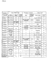
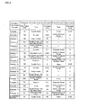
- Examples 1 to 9 are cases where the binder layer is made of organic resin and examples 10 to 18 are cases where the binder layer is made of an inorganic material. The conditions are described together on the tables of Figs.4 and 5 .
- Acrylic urethane resin was coated on the surface of electrolytic galvanized steel sheet (both-side plating, Zn plating amount on one side: 20g/m 2 ) having the plate thickness of 0.5mm and dried. The coating thickness after drying was set to approximately 1 ⁇ m. Subsequently, the silver film was coated by silver mirror reaction at the thickness of approximately 70nm. Next, acrylic resin was coated on the surface of the silver film and dried. The film thickness after drying was set to approximately 6 ⁇ m. Moreover, aqueous solution containing silica sol was coated and dried. The thickness of silica film after drying was set to 0.05 ⁇ m.
- Zinc phosphate treatment having the film thickness of 1000mg/m 2 was applied on the surface of electrolytic galvanized steel sheet (both-side plating, Zn plating amount on one side: 20g/m 2 ) having the plate thickness of 0.5mm, polyester resin film having the thickness of 15 ⁇ m was laminated on the zinc phosphate treated film by thermo-compression bonding. Subsequently, on the top of it, the silver film was coated at the thickness of 150nm by silver mirror reaction. Next, the substrate was immersed into aqueous solution containing alumina sol, and alumina film was coated on the surface of the silver film at the thickness of 0.03 ⁇ m. Moreover, acrylic urethane resin was coated on the surface of alumina film and dried. The coating thickness after drying was set to 6 ⁇ m.
- a hot-dipped zinc-55 % by mass aluminum alloy plating steel sheet having the plate thickness of 0.5mm was prepared. Note that the steel sheet is called a Galvalume steel sheet.
- Polycarbonate resin was coated on the surface thereof and dried. The coating thickness after drying was set to 5 ⁇ m.
- the silver film was coated at the thickness of 100nm by silver mirror reaction.
- acrylic resin was coated on the surface of the silver layer and dried. The coating thickness after drying was set to 25 ⁇ m.
- ABS resin acrylonitrile-butadiene-styrene copolymer synthetic resin
- electrolytic galvanized steel sheet both-side plating, Zn plating amount on one side: 20g/m 2
- the thickness after drying was set to 5 ⁇ m.
- the silver film was coated at the thickness of 83nm by silver mirror reaction.
- acrylic resin containing 3 % by mass of alumina was coated on the surface of the silver film and dried. The thickness after drying was set to 10 ⁇ m.
- Electrolytic zinc-cobalt-molybdenum composite coated steel sheet (both-side plating, Zn plating amount on one side: 20g/m 2 ) having the plate thickness of 0.5mm was prepared.
- Chromate treatment both-side processing, 40mg/m 2 of Cr attached per one side
- acrylic urethane resin was coated and dried. The coating thickness after drying was 10 ⁇ m.
- the silver film was coated at the thickness of 130nm by silver mirror reaction.
- acrylic urethane resin was coated on the surface of the silver film and dried. The coating thickness after drying was 6 ⁇ m.
- Electrolytic galvanized steel sheet (both-side plating, Zn plating amount on one side: 20g/m 2 ) having the plate thickness of 0.5mm was prepared.
- Chromate treatment both-side processing, 10mg/m of Cr attached per one side
- acrylic urethane resin was coated and dried.
- the coating thickness after drying was 15 ⁇ m.
- the silver film was coated at the thickness of 70nm by silver mirror reaction.
- the substrate was immersed into aqueous solution containing alumina sol, cathodic treatment was performed by using the substrate as a cathode and the stainless steel sheet as an anode, and dried. After drying, a coating thickness of alumina film deposited on the surface of the silver film on substrate was 0.1 ⁇ m.
- polyester resin was coated on the surface of alumina film and dried. The coating thickness after drying was 6 ⁇ m.
- a substrate made of stainless steel plate (SUS304) having the plate thickness of 0.5mm was prepared, and polyimide resin was coated on the surface thereof and dried.
- the film thickness after drying was 3 ⁇ m.
- the silver film was coated at the thickness of 150nm by silver mirror reaction.
- the substrate was immersed into aqueous solution containing zirconium oxide sol, cathodic treatment was performed by using the substrate as a cathode and the stainless steel sheet as an anode, and dried. After drying, a film thickness of zirconium oxide layer deposited on the surface of the silver film on the substrate was 0.05 ⁇ m.
- acrylic urethane resin was coated on the surface of zirconium oxide layer and dried. The coating thickness after drying was 8 ⁇ m.
- a substrate made up of Al plate (JIS H 4000, alloy number: 1050) having the plate thickness of 0.5mm was prepared, urethane resin was coated on the surface thereof and dried. The coating thickness after drying was 12 ⁇ m. Subsequently, the silver film was coated at the thickness of 120nm by silver mirror reaction. Next, acrylic resin containing 3 % by mass of silica was coated on the surface of the silver film and dried. The film thickness after drying was 15 ⁇ m. Moreover, acrylic urethane resin was coated on the surface of acrylic resin containing 3 % by mass of silica and dried. The coating thickness after drying was 3 ⁇ m.
- a substrate made of Al alloy plate (JIS H 4000, alloy number: 5052) having the plate thickness of 0.5mm was prepared, acrylic urethane resin was coated on the surface thereof and dried. The coating thickness after drying was 15 ⁇ m. Subsequently, the silver film was coated at the thickness of 75nm by silver mirror reaction. Next, polyester resin film having the thickness of 15 ⁇ m was laminated on the surface of the silver film by thermo-compression bonding. Moreover, acrylic resin containing 2 % by mass of silica was coated on polyester resin film surface and dried. The coating thickness after drying was 3 ⁇ m.
- Aqueous solution containing alumina sol was coated on the surface of electrolytic galvanized steel sheet (both-side plating, Zn plating amount on one side: 20g/m 2 ) having the plate thickness of 0.5mm, and dried.
- the thickness of alumina film after drying was 0.1 ⁇ m.
- the silver film was deposit at the thickness of 100nm by silver mirror reaction.
- acrylic resin was coated on the surface of the silver film and dried.
- the thickness after drying was 6 ⁇ m.
- aqueous solution containing silica sol was further coated and dried. The thickness of silica after drying was 0.05 ⁇ m.
- An electrolytic galvanized steel sheet (both-side plating, Zn plating amount on one side: 20g/m 2 ) having the plate thickness of 0.5mm was prepared.
- zinc phosphate treatment of the coating thickness of 700mg/m 2 was applied, and the galvanized steel sheet was immersed into aqueous solution containing silica sol, electrolytic treatment was performed on the top of the zinc phosphate treatment coating by aqueous solution containing silica sol by using the galvanized steel sheet as a cathode and the stainless steel sheet as an anode, and dried.
- silica layer having the layer thickness of 0.2 ⁇ m was deposited on the surface of the galvanized steel sheet.
- the silver film was deposit on the silica film at the thickness of 120nm by silver mirror reaction.
- the substrate was immersed into aqueous solution containing alumina sol, and alumina layer was deposited on the silver film at the layer thickness of 0.03 ⁇ m.
- acrylic urethane resin was coated on the alumina layer, and dried. The thickness after drying was 6 ⁇ m.
- Aqueous solution containing hafnium oxide sol was coated on the surface of hot-dipped zinc-55 % by mass aluminum alloy plated steel sheet having the plate thickness of 0.5mm, and dried.
- the thickness of hafnium oxide after drying was 1 ⁇ m.
- the silver film was deposit at the thickness of 150nm by silver mirror reaction.
- acrylic resin was coated on the surface of the silver film and dried. The thickness after drying was 25 ⁇ m.
- An electrolytic galvanized steel sheet (both-side plating, Zn plating amount on one side: 20g/m 2 ) having the plate thickness of 0.5mm was prepared.
- the galvanized steel sheet was immersed into aqueous solution containing titanium oxide sol, cathodic treatment was performed by using the galvanized steel sheet as a cathode and the stainless steel sheet as an anode, and dried. After drying, layer thickness of titanium oxide deposited on the surface of the silver film on substrate was 0.5 ⁇ m. Subsequently, the silver film was coated at the thickness of 50nm by silver mirror reaction. Next, acrylic resin containing 3 % by mass of alumina was coated on the surface of the silver film and dried. The thickness after drying was 10 ⁇ m.
- An electrolytic zinc-cobalt-molybdenum composite coated steel sheet (both-side plating, Zn plating amount on one side: 20g/m 2 ) having the plate thickness of 0.5mm was prepared.
- Chromate treatment both-side processing, 40mg/m 2 of Cr attached per one side
- aqueous solution containing zirconium oxide sol was coated on the top of it, and dried.
- the thickness of zirconium oxide film after drying was 2 ⁇ m.
- the silver film was coated at the thickness of 250nm by silver mirror reaction.
- acrylic urethane resin was coated on the surface of the silver film and dried.
- the thickness after drying was 6 ⁇ m.
- the above-described processed electrolytic galvanized steel sheet was immersed into aqueous solution containing silica sol and dried. Thus, silica layer having the thickness after drying of 0.1 ⁇ m was deposited.
- An electrolytic galvanized steel sheet (both-side plating, Zn plating amount on one side: 20g/m 2 ) having the plate thickness of 0.5mm was prepared.
- Chromate treatment both-side processing, 10mg/m 2 of Cr attached per one side
- the substrate was immersed into aqueous solution containing silica sol and alumina sol, cathodic treatment was performed by using the substrate as a cathode and the stainless steel sheet as an anode, and dried. After drying, the film thickness of layer made of mixture of silica and alumina, which was deposited on the substrate, was 3 ⁇ m. Subsequently, the silver film was deposited at the thickness of 70nm by silver mirror reaction.
- the substrate was immersed into aqueous solution containing alumina sol, cathodic treatment was performed by using the substrate as a cathode and the stainless steel sheet as an anode, and dried. After drying, the thickness of alumina layer deposited on the silver film surface of the substrate was 0.1 ⁇ m. Moreover, polyester resin was further coated on the surface of the alumina layer and dried. The thickness after drying was 6 ⁇ m.
- a substrate made up of stainless steel plate (SUS304) having the plate thickness of 0.5mm was prepared, silica was coated on the surface thereof and dried. Specifically, the substrate was immersed into aqueous solution containing silica sol, cathodic treatment was performed by using the substrate as a cathode and the stainless steel plate as an anode, and the layer thickness after drying was 0.2 ⁇ m. Subsequently, the silver film was coated at the thickness of 150nm by silver mirror reaction. Next, the substrate was immersed into aqueous solution containing silica sol, cathodic treatment was performed by using the substrate as a cathode and the stainless steel plate as an anode, and dried. After drying, the thickness of silica layer deposited on the surface of the silver film on substrate was 0.05 ⁇ m. Moreover, acrylic urethane resin was coated on the surface of silica film and dried. The layer thickness after drying was 8 ⁇ m.
- An Al plate (JIS H 4000, alloy number: 1050) having the plate thickness of 0.5mm was prepared, and alumina was coated on the surface thereof and dried.
- the substrate was immersed into aqueous solution containing alumina sol, cathodic treatment was performed by using the substrate as a cathode and the stainless steel plate as an anode, and the layer thickness after drying was 0.3 ⁇ m.
- the silver film was coated at the thickness of 120nm by silver mirror reaction.
- acrylic resin containing 3 % by mass of silica was coated on the surface of the silver film and dried. The film thickness after drying was 15 ⁇ m.
- acrylic urethane resin was coated on the surface of acrylic resin containing 3 % by mass of silica, and dried. The thickness after drying was 3 ⁇ m.
- An Al alloy plate (JIS H 4000, alloy number: 5052) having the plate thickness of 0.5mm was prepared, and mixture of alumina and silica was coated on the surface thereof and dried.
- the substrate was immersed into aqueous solution containing alumina sol and silica sol, cathodic treatment was performed by using the substrate as a cathode and the stainless steel plate as an anode, and the thickness after drying was 0,1 ⁇ m.
- the silver film was coated at the thickness of 75nm by silver mirror reaction.
- polyester resin film having the thickness of 15 ⁇ m was laminated on the surface of the silver film by thermo-compression bonding.
- acrylic resin containing 2 % by mass of silica was coated on the surface of polyester resin film, and dried. The thickness after drying was 3 ⁇ m.
- Silver film was coated at the thickness of 70nm on the surface of electrolytic galvanized steel sheet (both-side plating, Zn plating amount on one side: 20g/m 2 ) having the plate thickness of 0.5mm by silver mirror reaction. Next, acrylic resin was coated on the surface of the silver film and dried. The thickness after drying was 40 ⁇ m. On the top of it, aqueous solution containing silica sol was further coated and dried. The thickness of silica after drying was 0.05 ⁇ m.
- CM-3500d (light source:D65, aperture :8mm) manufactured by Minolta was used as a measurement device, and light reflectance at wavelength 550nm was measured according to JIS Z8722. Note that calibration was performed based on the reflectance of a barium sulfate standard white plate.
- Light reflectance of 90% or more was indicated by ⁇ mark and less than 90% was indicated by X mark. Light reflectance of 90% or more is practical and it was set as an acceptable range.
- the test was performed by adhering adhesive tape on the light reflecting plate and peeling it off. One having film peel was indicated by ⁇ mark, and one having no film peel was indicated by ⁇ mark.
- film peel did not occur in Examples 1 to 18 because the binder layer was provided. Further, since the thickness of the protective layer 4 is 5 to 30 ⁇ m, deterioration of regular reflectance with time is small and satisfactory.
- Comparative example 1 since Comparative example 1 was not provided with the binder layer, film peel occurred at the interface between the galvanized steel sheet and the silver film. Further, it had a large reduction rate of regular reflectance.
- the binder layer 2 made of organic resin or an inorganic material is laid between the substrate 1 made of metal plate and the reflective layer 3 made up of a plated layer of silver or silver alloy having silver as a main component.
- the reflective layer 3 made of the plated layer can be formed on the substrate 1 made of metal plate with good adhesiveness.
- the substrate 1 made of metal plate Since the substrate 1 made of metal plate is used, it has excellent workability and strength comparing to a glass substrate. In the case of using the substrate 1 in which galvanization or zinc alloy plating is applied to steel sheet, it is inexpensive comparing to stainless steel plate, aluminum plate or aluminum alloy plate.
- the binder layer 2 being the base of the reflective layer 3 is formed by a coating method using organic resin or an inorganic material, the surface of the binder layer 2 can be easily made flat, the reflective layer 3 on the binder layer 2 becomes flat, the light reflecting plate with high regular reflectance can be obtained.
- the reflective layer 3 that functions to reflect light is made up of silver or silver alloy having silver as a main component, and formed by a plating method, so that it does not require an expensive manufacturing facility unlike a vacuum evaporation process, and can be manufactured inexpensively.
- reflected light tends to be yellowish. This is considered to be because the silver film or the like absorbs light of a wavelength corresponding to blue. Then, this embodiment had a constitution that blue system pigment was added to the protective layer 4.
- the protective layer 4 is a single substance of organic resin or an inorganic material or a single layer made of their mixture, the protective layer 4 is allowed to contain blue system pigment;
- the protective layer 4 is two layers using organic resin film as a lower layer and using inorganic material film as an upper layer, at least either one layer of the upper layer or the lower layer is allowed to contain blue system pigment;
- the protective layer 4 is two layers using inorganic material film as a lower layer and using organic resin film as an upper layer, at least either one layer of the upper layer or the lower layer is allowed to contain blue system pigment.
- blue system pigment cobalt blue, cobalt purple, ultramarine, Berlin blue, phthalocyanine blue, indanthrene blue, cerulean blue or Prussian blue can preferably be used.
- loadings of blue system pigment to the protective layer be a range of 0.05 to 0.5 % by mass.
- blue system pigment is added such that the total loadings on two layers of the protective layer become the range of 0.05 to 0.5 % by mass. Loadings of less than 0.05 % by mass is not effective to the reflection of blue system color. On the other hand, if the loadings exceed 0.5 % by mass, too much blue system color is reflected and yellow being the complementary color of blue is absorbed conversely, and light significantly different from white light is created.
- the blue system pigment in the protective layer 4 reflects blue system light, and absorption of blue system light by the reflective layer 3 made of the silver film or silver alloy film is compensated, light does not create particular color but reflected light directly from the color of sunlight or the light of a light source can be obtained.
- the method of depositing the protective layer 4 of this embodiment can be used.
- the method of depositing the protective layer of the first embodiment can be used.
- Fig.2 is a perspective view showing a constitution of a mirror duct 102 according to the third embodiment of the present invention.
- Fig.2 shows a state where the mirror duct 102 is installed in a house.
- the mirror duct 102 is equipped with a daylighting section 5, a light emitting section 6 and a light guiding section 7 as shown in Fig.2 .
- the light reflecting plate 101 described in the first embodiment is formed on the inner wall of a partition wall 8 of the light guiding section 7.
- the mirror duct 102 is fabricated by processing the light reflecting plate 101.
- the daylighting section 5 is exposed to the outside so as to receive sunlight, and the light emitting section 6 is installed so as to be exposed to the inside as shown in Fig.2 .
- the mirror duct 102 described above it is fabricated by using the light reflecting plate 101 described in the first embodiment, and a mirror duct having high reliability and light reflectance due to no film peel can be provided inexpensively.
- illumination light of the mirror duct does not create particular color but directly shows the color of sunlight.
- Fig.3A is a perspective view showing a constitution of an edge-lighting type backlight of a liquid crystal display device 103 according to the third embodiment of the present invention.
- Fig.3B is a cross-sectional view taken along line I-I of Fig.3A .
- the backlight 103 is provided under a liquid crystal panel 14 as shown in Fig.3A .
- the backlight 103 is equipped with a light guiding plate 9, which has an area corresponding to the surface area of a liquid crystal monitor and where irregular reflecting sections or diffused reflecting sections (not shown) are dispersedly provided on a rear surface, reflecting plates 10a, 10b provided on the rear surface and the side surface of the light guiding plate 9, a light source 11 provided on one side end portion of the light guiding plate 9 , a reflecting plate 12 that reflects light from the light source 11 toward the light guiding plate 9, and a diffusing sheet 13 that diffuses reflected and transmitted light that is outputted from the surface of the light guiding plate 9.
- the reflecting plates 10a, 10b provided on the rear surface and the side surface of the light guiding plate 9 were fabricated by processing the above-described light reflecting plate 101. Further, the reflecting plate 12 is also fabricated by processing the light reflecting plate 101.
- the backlight 103 In the backlight 103, light outputted from the light source 11 is reflected and transmitted inside the light guiding plate 9 while performing total reflection to make the light reach the entire light guiding plate 9. Then, acute-angled reflected light occurs by the irregular reflecting sections or the diffused reflecting sections dispersedly provided on the rear surface of the light guiding plate 9, and its reflected light is made incident to the surface of the light guiding plate 9 at a smaller incident angle than an incident angle that makes total reflection. The light is outputted from the surface of the light guiding plate 9 to the outside. Then, outputted light passes through the diffusing sheet 13 to generate diffused light, and the diffused light is used as backlight of the liquid crystal panel 14.
- the reflecting plate 10a on the rear surface of the light guiding plate 9 returns light leaked from the rear surface of the light guiding plate 9 to the light guiding plate 9, and the reflecting plate 10b returns light leaked from the side surface of the light guiding plate 9 to the light guiding plate 9.
- the edge-lighting type backlight 103 described above the light reflecting plate 101 described in the first embodiment is used, and an edge-lighting type backlight having high reliability and high light reflectance due to no film peel can be provided inexpensively.
- the edge-lighting type backlight can output light having the color of light directly from a light source.
- liquid crystal display device equipped with the above-described edge-lighting type backlight is also included in the scope of the present invention.
- images to be displayed show natural color.
- a liquid crystal display device equipped with the light reflecting plate of this invention which is provided under the liquid crystal panel, reflects external incident light and radiates it toward a liquid crystal, is also included in the scope of the present invention.
- images to be displayed show natural color.
- the light reflecting plate of the first embodiment can be used as the light reflecting plate of an illumination fixture such as a reflecting plate of light outputted from a fluorescent lamp or a mercury lamp, for example.
- the light reflecting plate 101 described in the first embodiment is used in this illumination fixture, an illumination fixture having high reliability due to no film peel of the light reflecting plate 101 and high light reflectance can be provided inexpensively.
- illumination light of an illumination fixture directly shows the color of the light from a light source.
- optical devices such as a rear projection image display device, a scanner and a copier, which is equipped with the light reflecting plate of the first and the second embodiments are also included in the scope of the present invention.
- the light reflecting plate of the present invention Since the light reflecting plate of the present invention has high reliability due to no film peel, high light reflectance, and inexpensiveness, it is optimally used as a light reflecting plate of a mirror duct, an illumination fixture, an edge-lighting type backlight, a liquid crystal display device, a reflector for flash use of a digital camera, a freezer showcase or other optical devices.
- the illumination fixture the invention is applicable to a light source using a fluorescent lamp or a mercury lamp, or a downlight.
Landscapes
- Physics & Mathematics (AREA)
- Chemical & Material Sciences (AREA)
- General Physics & Mathematics (AREA)
- Optics & Photonics (AREA)
- Mechanical Engineering (AREA)
- Chemical Kinetics & Catalysis (AREA)
- Engineering & Computer Science (AREA)
- Materials Engineering (AREA)
- General Chemical & Material Sciences (AREA)
- Metallurgy (AREA)
- Organic Chemistry (AREA)
- Laminated Bodies (AREA)
- Optical Elements Other Than Lenses (AREA)
- Arrangement Of Elements, Cooling, Sealing, Or The Like Of Lighting Devices (AREA)
- Non-Portable Lighting Devices Or Systems Thereof (AREA)
- Other Surface Treatments For Metallic Materials (AREA)
Applications Claiming Priority (3)
| Application Number | Priority Date | Filing Date | Title |
|---|---|---|---|
| JP2007153120 | 2007-06-08 | ||
| JP2007153119 | 2007-06-08 | ||
| PCT/JP2008/059691 WO2008149717A1 (fr) | 2007-06-08 | 2008-05-27 | Plaque réfléchissant la lumière, procédé de fabrication de celle-ci, et dispositif réfléchissant la lumière |
Publications (2)
| Publication Number | Publication Date |
|---|---|
| EP2157456A1 true EP2157456A1 (fr) | 2010-02-24 |
| EP2157456A4 EP2157456A4 (fr) | 2011-11-02 |
Family
ID=40093538
Family Applications (1)
| Application Number | Title | Priority Date | Filing Date |
|---|---|---|---|
| EP08764724A Ceased EP2157456A4 (fr) | 2007-06-08 | 2008-05-27 | Plaque réfléchissant la lumière, procédé de fabrication de celle-ci, et dispositif réfléchissant la lumière |
Country Status (6)
| Country | Link |
|---|---|
| US (1) | US8064014B2 (fr) |
| EP (1) | EP2157456A4 (fr) |
| JP (1) | JP5457176B2 (fr) |
| CN (1) | CN101669045B (fr) |
| TW (1) | TWI481931B (fr) |
| WO (1) | WO2008149717A1 (fr) |
Families Citing this family (35)
| Publication number | Priority date | Publication date | Assignee | Title |
|---|---|---|---|---|
| US20110311807A1 (en) * | 2008-06-20 | 2011-12-22 | Akzo Nobel Coatings International B.V. | Flexible substrates having reduced shrinkage and curling |
| JP5266082B2 (ja) * | 2009-02-13 | 2013-08-21 | 三菱樹脂株式会社 | 導光板 |
| JP5747823B2 (ja) * | 2010-02-05 | 2015-07-15 | コニカミノルタ株式会社 | フィルムミラー、太陽熱発電用フィルムミラー及び太陽光発電用反射装置 |
| KR101388471B1 (ko) * | 2010-06-24 | 2014-04-23 | 양신호 | 액정표시모듈의 바텀 케이스 제조방법 |
| CN102544380B (zh) * | 2010-12-25 | 2015-08-26 | 比亚迪股份有限公司 | 一种太阳能电池背板及其制备方法及一种太阳能电池 |
| WO2012090987A1 (fr) * | 2010-12-28 | 2012-07-05 | コニカミノルタオプト株式会社 | Pellicule fonctionnelle, miroir pelliculaire et dispositif réfléchissant permettant de produire une puissance thermique solaire |
| CN102540295A (zh) * | 2010-12-29 | 2012-07-04 | 盛玉林 | 反射片 |
| JP5829028B2 (ja) * | 2011-01-26 | 2015-12-09 | 東洋鋼鈑株式会社 | 光反射板、光反射板の製造方法およびそれを用いた照明用部材 |
| CN102455450A (zh) * | 2011-01-27 | 2012-05-16 | 昆山市诚泰电气股份有限公司 | 反射片 |
| CN102691046B (zh) * | 2011-03-25 | 2015-10-14 | 鸿富锦精密工业(深圳)有限公司 | 抗菌镀膜件及其制备方法 |
| JP6023405B2 (ja) * | 2011-06-10 | 2016-11-09 | 東洋鋼鈑株式会社 | 植物工場用の採光装置および植物の育成方法 |
| CN102590909B (zh) * | 2012-03-02 | 2014-04-02 | 青岛海信电器股份有限公司 | 一种反射片和液晶模组 |
| KR101304715B1 (ko) * | 2012-04-25 | 2013-09-06 | 주식회사 엘지씨엔에스 | 도광판에서의 빛 누출 방지 방법 및 그 장치와 반사재가 토출된 도광판을 가지는 디스플레이 장치 |
| JP6243106B2 (ja) * | 2012-07-17 | 2017-12-06 | 東洋鋼鈑株式会社 | 光反射板の製造方法、光反射板およびそれを用いた照明用部材 |
| CN102953032A (zh) * | 2012-10-20 | 2013-03-06 | 浙江笙富精密科技有限公司 | 一种真空蒸镀银膜的方法及设备 |
| JP2014201801A (ja) * | 2013-04-05 | 2014-10-27 | カヤバ工業株式会社 | 銀メッキ構造体 |
| CN103552315A (zh) * | 2013-10-26 | 2014-02-05 | 王兆进 | 一种反射板 |
| US9236545B2 (en) * | 2013-11-18 | 2016-01-12 | Ge Lighting Solutions Llc | Hybrid metallization on plastic for a light emitting diode (LED) lighting system |
| CN104691028A (zh) * | 2015-03-20 | 2015-06-10 | 武汉理工大学 | 一种高反射隔热层材料及其制备方法 |
| CN105182463A (zh) | 2015-08-14 | 2015-12-23 | 深圳市华星光电技术有限公司 | 一种导光板及显示装置 |
| CN105161963B (zh) * | 2015-09-30 | 2018-11-23 | 中国工程物理研究院激光聚变研究中心 | 一种片状激光放大器 |
| CN105161964B (zh) * | 2015-09-30 | 2018-11-23 | 中国工程物理研究院激光聚变研究中心 | 一种片状激光放大器 |
| CN105974664B (zh) * | 2016-06-21 | 2019-12-31 | 青岛海信电器股份有限公司 | 背光模组、显示装置及背光模组的制作方法 |
| JP6816414B2 (ja) * | 2016-09-02 | 2021-01-20 | コニカミノルタ株式会社 | 光反射フィルム及び液晶表示装置用バックライトユニット |
| CN116679845A (zh) | 2017-02-06 | 2023-09-01 | 平蛙实验室股份公司 | 触摸感测装置 |
| CN206929725U (zh) * | 2017-05-12 | 2018-01-26 | 深圳市光峰光电技术有限公司 | 波长转换装置和激光荧光转换型光源 |
| US11256371B2 (en) | 2017-09-01 | 2022-02-22 | Flatfrog Laboratories Ab | Optical component |
| WO2019172826A1 (fr) | 2018-03-05 | 2019-09-12 | Flatfrog Laboratories Ab | Appareil de détection tactile perfectionné |
| CN111886132B (zh) * | 2018-03-29 | 2022-12-06 | 日本制铁株式会社 | 被覆金属板及具有该被覆金属板的接合件 |
| US11067808B2 (en) * | 2018-07-24 | 2021-07-20 | Magic Leap, Inc. | Diffractive optical elements with mitigation of rebounce-induced light loss and related systems and methods |
| CN108845459A (zh) * | 2018-07-25 | 2018-11-20 | 武汉华星光电技术有限公司 | 一种反射片及背光模组 |
| US12055969B2 (en) | 2018-10-20 | 2024-08-06 | Flatfrog Laboratories Ab | Frame for a touch-sensitive device and tool therefor |
| CN114730228A (zh) | 2019-11-25 | 2022-07-08 | 平蛙实验室股份公司 | 一种触摸感应设备 |
| WO2021158164A1 (fr) | 2020-02-08 | 2021-08-12 | Flatfrog Laboratories Ab | Appareil tactile à interactions à faible latence |
| KR102453007B1 (ko) | 2020-12-18 | 2022-10-12 | 주식회사 포스코 | 가공 후 내식성이 우수한 복합 도금강판 및 이의 제조방법 |
Family Cites Families (19)
| Publication number | Priority date | Publication date | Assignee | Title |
|---|---|---|---|---|
| JPS5032055B2 (fr) * | 1972-01-19 | 1975-10-17 | ||
| DE3032315C2 (de) | 1980-08-27 | 1985-06-27 | Transformatoren Union Ag, 7000 Stuttgart | Spartransformator für hohe Nennspannung und mit großer Nennleistung |
| JPS5775408U (fr) * | 1980-10-28 | 1982-05-10 | ||
| DE3107612A1 (de) * | 1981-02-27 | 1982-09-16 | Siemens AG, 1000 Berlin und 8000 München | Laserspiegel, insbesondere laser-polygonspiegel |
| JP3054241B2 (ja) * | 1991-07-23 | 2000-06-19 | 三菱伸銅株式会社 | 光反射体 |
| JPH0671808A (ja) * | 1992-08-26 | 1994-03-15 | Kobe Steel Ltd | 成形加工性に優れた反射体用めっき金属板 |
| US5361172A (en) * | 1993-01-21 | 1994-11-01 | Midwest Research Institute | Durable metallized polymer mirror |
| TW314600B (fr) * | 1995-05-31 | 1997-09-01 | Mitsui Toatsu Chemicals | |
| CN2257930Y (zh) * | 1995-08-22 | 1997-07-16 | 张忠武 | 复合反光镜面板 |
| ATE216502T1 (de) * | 1997-11-17 | 2002-05-15 | Alanod Al Veredlung Gmbh | Verbundmaterial, insbesondere für reflektoren |
| JPH11183713A (ja) * | 1997-12-24 | 1999-07-09 | Mitsui Chem Inc | 反射体 |
| AU1018599A (en) | 1998-11-12 | 2000-06-05 | Alanod Aluminium-Veredlung Gmbh & Co. | Reflector with a resistant surface |
| JP2001235798A (ja) * | 1999-12-17 | 2001-08-31 | Nippon Sheet Glass Co Ltd | 反射ミラー及びこれを用いた背面投写型ディスプレイ |
| JP2003255467A (ja) * | 2002-02-28 | 2003-09-10 | Hitachi Ltd | 光学ユニット及びそれを用いる映像表示装置 |
| TW575197U (en) * | 2003-04-30 | 2004-02-01 | Toppoly Optoelectronics Corp | Backlight plate module |
| WO2005081021A1 (fr) * | 2004-02-24 | 2005-09-01 | Matsushita Electric Works, Ltd. | Réflecteur de lumière et système d’éclairage englobant ledit réflecteur |
| TWI313377B (en) * | 2004-03-16 | 2009-08-11 | Innolux Display Corp | Liquid crystal display device |
| JP2005326434A (ja) * | 2004-05-12 | 2005-11-24 | Hitachi Ltd | 反射ミラー及びそれを用いた背面投射型映像表示装置 |
| JP4655813B2 (ja) * | 2005-08-09 | 2011-03-23 | 株式会社日立製作所 | リフレクタ及びそれを用いた投射型画像表示装置 |
-
2008
- 2008-05-27 WO PCT/JP2008/059691 patent/WO2008149717A1/fr not_active Ceased
- 2008-05-27 EP EP08764724A patent/EP2157456A4/fr not_active Ceased
- 2008-05-27 CN CN2008800140419A patent/CN101669045B/zh not_active Expired - Fee Related
- 2008-05-27 JP JP2009517805A patent/JP5457176B2/ja not_active Expired - Fee Related
- 2008-06-03 TW TW097120569A patent/TWI481931B/zh not_active IP Right Cessation
-
2009
- 2009-09-18 US US12/585,612 patent/US8064014B2/en not_active Expired - Fee Related
Also Published As
| Publication number | Publication date |
|---|---|
| TWI481931B (zh) | 2015-04-21 |
| CN101669045A (zh) | 2010-03-10 |
| EP2157456A4 (fr) | 2011-11-02 |
| US20100014024A1 (en) | 2010-01-21 |
| WO2008149717A1 (fr) | 2008-12-11 |
| JP5457176B2 (ja) | 2014-04-02 |
| US8064014B2 (en) | 2011-11-22 |
| TW200905317A (en) | 2009-02-01 |
| JPWO2008149717A1 (ja) | 2010-08-26 |
| CN101669045B (zh) | 2012-06-13 |
Similar Documents
| Publication | Publication Date | Title |
|---|---|---|
| EP2157456A1 (fr) | Plaque réfléchissant la lumière, procédé de fabrication de celle-ci, et dispositif réfléchissant la lumière | |
| EP2172793B1 (fr) | Plaque de réflexion de lumière, procédé de fabrication d'une plaque de réflexion de lumière et appareil de réflexion de lumière | |
| JP5081502B2 (ja) | 光反射板 | |
| EP2371533B1 (fr) | Film stratifié transparent et procédé de production associé | |
| US9255030B2 (en) | Concentration-modulated coatings | |
| US20090052041A1 (en) | Anti-Reflection Film and Polarizing Plate Using the Same | |
| KR101758539B1 (ko) | 투명 적층 필름 | |
| US9341748B2 (en) | Mirror for use in humid environments, and/or method of making the same | |
| EP2833173A1 (fr) | Matériau de protection contre les rayons de chaleur et structure laminée | |
| JP2012030577A (ja) | 透明積層フィルム | |
| US20130208375A1 (en) | Mirror and methods of making the same | |
| WO2013153923A1 (fr) | Réflecteur solaire | |
| ES2733581T3 (es) | Espejo | |
| EP3243655B1 (fr) | Stratifié transmettant la lumière pour applications optiques | |
| AU616050B2 (en) | Surface priming of polycarbonate substrates | |
| WO2004113247A1 (fr) | Miroir | |
| KR20250069402A (ko) | 반사 필름 | |
| KR20250120163A (ko) | 반사 필름 | |
| JP6243106B2 (ja) | 光反射板の製造方法、光反射板およびそれを用いた照明用部材 | |
| WO2014120627A1 (fr) | Miroir et ses procédés de fabrication |
Legal Events
| Date | Code | Title | Description |
|---|---|---|---|
| PUAI | Public reference made under article 153(3) epc to a published international application that has entered the european phase |
Free format text: ORIGINAL CODE: 0009012 |
|
| 17P | Request for examination filed |
Effective date: 20091208 |
|
| AK | Designated contracting states |
Kind code of ref document: A1 Designated state(s): AT BE BG CH CY CZ DE DK EE ES FI FR GB GR HR HU IE IS IT LI LT LU LV MC MT NL NO PL PT RO SE SI SK TR |
|
| AX | Request for extension of the european patent |
Extension state: AL BA MK RS |
|
| DAX | Request for extension of the european patent (deleted) | ||
| A4 | Supplementary search report drawn up and despatched |
Effective date: 20110929 |
|
| RIC1 | Information provided on ipc code assigned before grant |
Ipc: C23C 18/44 20060101ALI20110923BHEP Ipc: G02B 6/00 20060101ALN20110923BHEP Ipc: G02B 5/08 20060101AFI20110923BHEP |
|
| 17Q | First examination report despatched |
Effective date: 20140107 |
|
| REG | Reference to a national code |
Ref country code: DE Ref legal event code: R003 |
|
| STAA | Information on the status of an ep patent application or granted ep patent |
Free format text: STATUS: THE APPLICATION HAS BEEN REFUSED |
|
| 18R | Application refused |
Effective date: 20160920 |