EP2157533A1 - Procédé d'identification de récipients médicaux - Google Patents
Procédé d'identification de récipients médicaux Download PDFInfo
- Publication number
- EP2157533A1 EP2157533A1 EP08162838A EP08162838A EP2157533A1 EP 2157533 A1 EP2157533 A1 EP 2157533A1 EP 08162838 A EP08162838 A EP 08162838A EP 08162838 A EP08162838 A EP 08162838A EP 2157533 A1 EP2157533 A1 EP 2157533A1
- Authority
- EP
- European Patent Office
- Prior art keywords
- code
- light source
- image
- light
- imaging system
- Prior art date
- Legal status (The legal status is an assumption and is not a legal conclusion. Google has not performed a legal analysis and makes no representation as to the accuracy of the status listed.)
- Withdrawn
Links
Images
Classifications
-
- G—PHYSICS
- G06—COMPUTING OR CALCULATING; COUNTING
- G06K—GRAPHICAL DATA READING; PRESENTATION OF DATA; RECORD CARRIERS; HANDLING RECORD CARRIERS
- G06K19/00—Record carriers for use with machines and with at least a part designed to carry digital markings
- G06K19/06—Record carriers for use with machines and with at least a part designed to carry digital markings characterised by the kind of the digital marking, e.g. shape, nature, code
- G06K19/06009—Record carriers for use with machines and with at least a part designed to carry digital markings characterised by the kind of the digital marking, e.g. shape, nature, code with optically detectable marking
- G06K19/06046—Constructional details
-
- G—PHYSICS
- G06—COMPUTING OR CALCULATING; COUNTING
- G06K—GRAPHICAL DATA READING; PRESENTATION OF DATA; RECORD CARRIERS; HANDLING RECORD CARRIERS
- G06K19/00—Record carriers for use with machines and with at least a part designed to carry digital markings
- G06K19/06—Record carriers for use with machines and with at least a part designed to carry digital markings characterised by the kind of the digital marking, e.g. shape, nature, code
- G06K19/06009—Record carriers for use with machines and with at least a part designed to carry digital markings characterised by the kind of the digital marking, e.g. shape, nature, code with optically detectable marking
- G06K19/06037—Record carriers for use with machines and with at least a part designed to carry digital markings characterised by the kind of the digital marking, e.g. shape, nature, code with optically detectable marking multi-dimensional coding
-
- B—PERFORMING OPERATIONS; TRANSPORTING
- B01—PHYSICAL OR CHEMICAL PROCESSES OR APPARATUS IN GENERAL
- B01L—CHEMICAL OR PHYSICAL LABORATORY APPARATUS FOR GENERAL USE
- B01L2300/00—Additional constructional details
- B01L2300/02—Identification, exchange or storage of information
- B01L2300/021—Identification, e.g. bar codes
-
- B—PERFORMING OPERATIONS; TRANSPORTING
- B41—PRINTING; LINING MACHINES; TYPEWRITERS; STAMPS
- B41M—PRINTING, DUPLICATING, MARKING, OR COPYING PROCESSES; COLOUR PRINTING
- B41M5/00—Duplicating or marking methods; Sheet materials for use therein
- B41M5/24—Ablative recording, e.g. by burning marks; Spark recording
Definitions
- the invention relates to a method and a device for the identification of medical containers.
- Such methods and devices are used in particular in the field of pharmacy or diagnostics to correctly identify medical containers, such as glass syringe bodies. In this way, for example, a safeguard against counterfeiting of medical products or a sub-mix protection when filling the medical containers can be ensured.
- the identification of medical containers by appropriate coding and labeling of pharmaceutical containers plays an important role.
- information such as a type of bottling, a bottler, a manufacturer, a date of manufacture, a recommended dosage or a use or the like, essential, which later, for example in the context of packaging the pharmaceutical containers or even by a user of the pharmaceutical material, to be easily retrieved.
- sub-mix protection A key point is the so-called sub-mix protection.
- Such a sub-mix protection should ensure that even in a plant in which different types of pharmaceutical materials and / or pharmaceutical materials with different properties - such as different drug concentrations - are filled, a confusion of containers is prevented.
- any types of markings which may be suitable as carriers of information can be used for the code itself.
- the information may change from container to container.
- screen-printed color codes or bar codes may be used.
- barcodes such as ink-jet printing, thermal transfer printing or laser printing.
- Such coded pharmaceutical containers such as in particular vitreous, can later be identified by reading this code.
- Printing methods or similar methods based on an ink or other dye have a number of disadvantages for the marking of pharmaceutical containers.
- a new material namely the dye or the ink
- introduced into a production or bottling plant whose compatibility with the rest of the process is not proven in all cases.
- a labeled container is usually subjected to environmental conditions in which the ink is slightly blurred or completely removed, for example by heat, solvents or similar conditions. If, on the other hand, the marking is applied only after filling, there may be a risk that the contents have already become confused at the time of application of the marking, for example by mixing different materials and / or concentrations of a material that are simultaneously filled in a line.
- codes generated in this way are very difficult to detect and read automatically. Since the codes generated in this way are only local, usually very small surface deformations, these codes can be seen with the naked eye, but automatic detection and decoding is very difficult in many cases. This is due in particular to the fact that the contrast of automatically generated images of these codes is very weak, so that conventional image recognition methods either completely fail or lead to high uncertainty with results. However, such uncertainties are intolerable, especially in the field of medical containers whose codes must be recognized with zero fault tolerance.
- the method and the device should allow a recording of a high-contrast image of the code, which is easily evaluated by means of automatic image recognition.
- a method and a device for identifying medical containers are proposed.
- the term of identification is to be understood in the context of the present invention and generally includes the detection of at least one piece of information about the container.
- the identification may include a recognition that the present container is a specific container.
- the result of such identification is in this case an information that it is a particular container.
- the identification may also lead to another type of coded and / or non-coded information, for example one or more of the following information: anonymous information, in particular a serial number; information about a content of the container; information about a bottler of a content of the container; information about a content of the container, in particular about the nature and / or quality of the content; information about an origin of the contents of the container, in particular about a manufacturer; information about use of the contents of the container; information on a best-before date and / or expiry date of the contents of the container. Also combinations of said information and / or other information are conceivable.
- the medical container can basically be any container which can also be used in medicine.
- medicine also includes the pharmaceutical industry, the diagnostics industry, the field of biological and / or medical samples or the like.
- the use for containers from other areas is possible, for example, containers from the field of daily life, the natural sciences or technology, for example, for containers in the food industry and / or in the field of packaging other types of consumables.
- the container may be medical containers made of glass. The following description will refer in essence to coded syringe bodies, in particular syringe bodies of glass.
- bottles, vials, ampoules, carpules, tubes or similar containers in particular containers made of glass or a glass-like material.
- other types of materials can be used.
- a code Under a code are generally markers to understand, which contain at least one piece of information. In this case, this information can be contained in encrypted form in the code. Alternatively or additionally, however, the code may also contain neutral information which is not encrypted. For example, serial numbers or the like can be mentioned here.
- the code can already be recognizable and / or decryptable for a human, so that even a human can read the at least one piece of information at least in a rough version.
- the code may include alphanumeric characters.
- the code can also be such that it is only by means of a machine, for example a computer, after the code has been read, that it is possible to obtain the at least one piece of information.
- the code contains at least one barcode, preferably a one- or two-dimensional barcode.
- the barcode comprises a so-called data matrix code, ie a two-dimensional code in which a two-dimensional bit pattern is used.
- This bit pattern is usually composed of so-called modules as the smallest information units. Depending on whether these modules are marked with a dot (also referred to below as "pixel") or not, these modules numerically assume the value 0 or 1 or vice versa. In this way, the modules become carriers of digital information.
- dot also referred to below as "pixel”
- other types of patterns than two-dimensional data matrix codes are possible, for example, one-dimensional dot patterns, for example, with a one-dimensional stringing together of modules of the type described.
- the method and the device are used to identify the medical container, which may include reading the at least one code from a surface of the medical container.
- reading is understood to mean a process in which the code is detected such that, in a further sub-step of the method or in an additional sub-step not belonging to the method, the at least one information contained in the code is determined can be, for example, the encrypted information and / or the serial number.
- the term "readout" is to be understood in the context of the present invention.
- the method may further include even applying the code.
- a code is used according to the invention, in which at least one surface of the medical container is provided with a plurality of pixels each having at least one recess.
- the code for example, the data matrix code of the type described above, for example, according to the known from the prior art method of DE 101 22 335 C1 and DE 102 34 002 A1 be generated.
- the surface of the medical container can be marked with a laser, in particular a pulsed laser, in particular a pulsed laser in the infrared spectral range. As indicated above, this marking is preferably carried out at a temperature above the glass transition temperature.
- a CO 2 laser can be used. In principle, however, it is also possible to use other methods for labeling, for example, those in WO 2006/117692 A1 described method.
- the code is designed such that it has a plurality of pixels each having at least one recess.
- the code may include a plurality of modules, where each module may or may not be tagged with a pixel.
- these modules can again assume the value 0 or 1 or vice versa and can thus again be bearers of binary information.
- the at least one depression wherein preferably exactly one depression per pixel is provided, may for example be rounded, in particular semicircular or lens-shaped.
- a light source is to be understood as meaning a source of electromagnetic radiation in the visible and / or infrared and / or ultraviolet spectral range, the electromagnetic radiation being emitted in such a way that it reaches at least a portion of the surface provided with the code.
- an image capture system is used to capture an image of the code.
- this image acquisition system may in particular comprise an image sensor for recording image data.
- This image sensor can be adapted to the type of code, for example.
- this image sensor may comprise a one- or two-dimensional array of individual photosensitive elements.
- the image sensor may comprise a CCD and / or CMOS chip.
- image information can be obtained from the code, ie the complete code or a part of this code, by means of the image acquisition system. record, which, for example, is directly evaluated and / or can be further processed later.
- the method and the device can correspond to at least largely known methods and devices.
- the lighting technology plays a crucial role.
- Conventional methods and devices which have been developed in particular from the field of recognition of non-transparent, printed codes on paper, such as printed bar codes, use different lighting techniques for detecting the code.
- diffuse light sources are used for illumination in incident-light methods or transmission methods, ie generally planar light sources. These light sources act as so-called Lambertian emitters and emit light in all spatial directions in front of the light source.
- such diffuse light sources can also be produced, for example, by means of groundscreens or the like.
- the light used according to the invention for the illumination differs from diffuse light sources which emit in all spatial directions.
- the marginal rays can be configured, for example, in the form of a circular cone or ellipsis. It is particularly preferred if the bundled light beam in the region of the surface is at least partially configured as a convergent light beam, that is to say as a light beam whose marginal rays converge toward one another.
- a collimated light beam in particular a convergent light beam, is generated from a light of the light source.
- the surface of the medical container is at least partially illuminated.
- the surface provided with the code can be wholly or partially illuminated.
- An imaging system is to be understood as a system which has at least one element with imaging properties.
- the imaging system may comprise at least one lens, in particular at least one converging lens and / or at least one curved mirror, for example a parabolic mirror.
- Complex imaging systems such as lenses, can be used to create the focused light beam.
- imaging systems which have exactly one converging lens. Even more complex lens systems are possible.
- the invention is based on the recognition that in the case of diffuse light sources, a large number of possible ray paths exist which circumvent a pixel or the depression received therein and which nevertheless appear to come for a viewer from the direction of this pixel. As a result, the contrast of each pixel is greatly reduced, so that conventional image recognition systems, which are used for example in the printing industry to recognize printed barcodes on paper surfaces, can no longer make an evaluation of the information contained in the codes with these low contrasts. The separation of "black" pixels from the background does not succeed in these cases.
- the apparatus and the method according to the invention thus provide means which enable a correct readout of the code and a recognition of the code by means of conventional image processing techniques, without the complex image processing routines would be required.
- the code can thus be read error-free or at least virtually error-free.
- the image processing system and the light source are arranged on opposite sides of the surface. This means that a transmission method is used for the illumination in which a material of the medical Container is illuminated by the light from the light source and the light beam.
- a transmission method is used for the illumination in which a material of the medical Container is illuminated by the light from the light source and the light beam.
- other techniques are possible in principle.
- the light source is imaged onto the coded surface.
- the imaging system has a focal length f
- the light source is at a distance g from the imaging system (or a main plane of the imaging system) and the coded surface of the medical container is at a distance x from the imaging system (or main plane) of the imaging system
- it is particularly preferred if the following relation holds for the distance x: x 1 1 f - 1 G
- the light source is imaged exactly on the surface according to the so-called lens equation.
- a slight deviation from this exact mapping for example, a deviation of not more than 10%, preferably not more than 5% and more preferably not more than 1%. It is therefore preferred if the light source is imaged substantially on the coded surface, which should include an exact deviation including the said defocusing tolerances.
- a defocusing of an exact image can also be used selectively, for example in order to circumvent the center-beam problems described above.
- the individual pixels can be detected as black dots by the image acquisition system, which stand out sharply from a light background.
- the centers of these black pixels may have bright spots.
- deliberately induced defocusing these bright pixels can be optically "smeared” and thus at least largely eliminated.
- software-based image processing methods can also be used.
- a "Ausschmieren" for eliminating the bright central pixels by a deliberately induced defocusing of optics of the image capture system can be reach, for example, by defocusing a lens of the image acquisition system.
- the light source may be substantially point-shaped.
- substantially punctiform are also deviations from an exact point shape to understand, for example in the context of light sources, which have a light-emitting surface of only a maximum of 1mm 2 , preferably 0.5 mm 2 or less.
- Such light sources can be, for example, light-emitting diodes, in particular inorganic light-emitting diodes, which typically have light-emitting surfaces in the range of a few 100 ⁇ m 2 .
- the image acquisition system may comprise an image sensor, for example according to the embodiments described above.
- This image sensor is configured to capture image data, such as one or two-dimensional image data.
- the image capture system may include additional elements. It is particularly preferred if the image acquisition system further comprises an image recognition system. Under an image recognition system is a system to understand, which is able to recognize associated image areas of the image data based on their image information. For example, the pixels of the code can be detected in this way and / or it can be recognized whether or not a particular module of the code is marked with a pixel, that is to say having the information "1" or "0" (or vice versa).
- the image recognition system can be designed very simply.
- the image recognition system can be designed to distinguish the pixels from the background solely on the basis of a histogram analysis with a fixed gray value threshold.
- the image recognition system may be filed to detect pixels as closed dark regions, preferably as closed dark circles. This recognition can preferably take place exclusively on the basis of the mentioned gray value analysis and / or a histogram analysis. In this way, a pixel pattern can be recorded by means of the image recognition system, from which the information of the code can be directly read out.
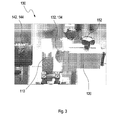
- syringe bodies 110 made of glass have been chosen, as used, for example, in US Pat FIG. 3 are recognizable.
- These syringe bodies 110 were prepared by a method such as that described in U.S. Pat DE 101 22 335 C1 or DE 102 34 002 A1 is marked by laser bombardment and thus on a surface 112, as for example in the FIGS. 4 and 5 recognizable, provided with a data matrix code 114.
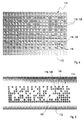
- This data matrix code 114 comprises a matrix of contiguous modules 116, which in FIG. 4 and in FIG.
- Each of these modules 116 which are arranged here into a two-dimensional matrix, can be marked with a pixel in the form of a depression 118, as in FIGS FIGS. 4 and 5 one of each of the marked modules 116 or not. Depending on whether a depression 118 is present or not, this module 116 may assume the binary value 1 or 0 (or vice versa).
- the laser marking can largely on the DE 101 22 335 C1 and the DE 102 334 002 A1 to get expelled.
- the syringe bodies 110 were heated to a temperature above the glass transition temperature, for example to a temperature of 580 ° C to 600 ° C, and subjected to laser pulses of a CO 2 laser.
- Such lasers are inexpensive and robust and can also be used on an industrial scale.
- the data matrix codes 114 produced by this method are characterized in that a dome-shaped impression, namely the recess 118, is formed at the point of insertion of the laser beam in the glass.
- This recess 118 is usually characterized in that the surface in the region of the recess 118 is approximately the same degree as the rest of the glass body of the surface 112.
- the recess 118 may in principle also assume another form, for example a Ellipse shape, a polygonal shape or the like. In any case, however, in most cases, a scattered lens effect will result from the depression 118.
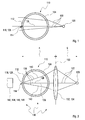
- FIG. 1 a conventional lighting technology is shown.
- a light source 120 is used, which is shown here only symbolically and which is usually designed as a diffuse light source.
- a transmitted light method is shown in which the light 122 of the light source 120 penetrates a glass body 124 of the syringe body 110 in order to arrive at the data matrix code 114.
- the light 122 is strongly scattered at the recesses 118 of the data matrix code 114, since these act as scattering lenses.
- the center beam denoted by the reference numeral 126 penetrates the recess 118 and passes undisturbed to a viewer. Even when directed light is used, highlights are produced at the edges of the recesses 118, which in the evaluation of the data matrix code 114 take the form of an insufficient quality parameter, which is referred to, for example, as "print growth" according to ISO 16022.
- Another unfavorable constellation results from a refraction of the light at the round glass surfaces 112 of the syringe body 110. These cause shading of the image, which also complicates the evaluation. Only rays of the light 122 having a very small aperture angle, ie, for example, a deviation from the optical axis of not more than 10 ° or less, reach the depression 118 and generate a shadow there.
- the result is essentially diffuse illumination, in which the rays incident from all directions do not produce useful contrast.
- FIG. 1 recorded surface 112 with a data matrix code 114 is, as described above, in FIG. 4 shown.
- the recesses 118 are recognizable as individual pixels 128 with the naked eye.
- the contrast of these pixels 128 is extremely weak, that is, these pixels 128 are insufficiently contrasted with the background of the surface 112.
- the prerequisite for a decoding or readout of the data matrix code 114 is the highest possible contrast between the pixels 128 and the background of the surface 112.
- Such a code according to FIG. 4 Therefore, it can only be decoded insufficiently or with high uncertainty.
- FIG. 2 On the other hand, an illumination method according to the invention and a device 130 for reading out a code are to FIG. 1 shown analog representation.
- the device 130 is in FIG. 3 shown again photographically.
- the device 130 in turn comprises a light source 120.
- this light source 120 may comprise a light-emitting diode, in particular an inorganic light-emitting diode.
- light-emitting diodes can be used which emit in the visible spectral range, for example light-emitting diodes which emit white light and / or red and / or green light.
- the device 130 comprises an imaging system 132, which in FIG. 2 only symbolically indicated.
- this imaging system 132 comprises a converging lens 134, for example a plano-convex converging lens 134 with a focal length of 10 to 30 mm. Even more complex embodiments of the imaging system 132 are conceivable in principle.
- the imaging system 132 is, as shown in the symbolic representation of the beam path in FIG. 2 established to generate a collimated light beam 136, in this case a convergent light beam 136.
- This collimated light beam 136 converges toward an optical axis 138, and preferably peripheral rays 140 of the collimated light beam 136 with the optical axis 138 enclose an angle which is not less than 10 °, preferably not less than 20 °.
- the depressions 118 of the data matrix code 114 represent scattering lenses. It is particularly preferred if the (positive) focal length of the converging lens 134 at least largely cancel out against the (negative) focal length of the depressions 118.
- the device 130 according to the Figures 2 and 3 an image capture system 142, which is in FIG. 2 is merely indicated.
- this image capture system 142 may have its own optics 144, for example, an image of the data matrix code 114 on an image sensor (in FIG. 3 not shown in FIG. 2 indicated by reference numeral 146), for example a CCD and / or CMOS chip.
- the image acquisition system 142 may include an image recognition system (also not shown in the figures) which may be incorporated in FIG FIG. 2 designated by the reference numeral 148. This can for example be part of a camera or can also be arranged separately, for example in a computer system, which is set up to evaluate image data of the image sensor 146 and to read out or decode the data matrix code 114.
- the illustrated device 130 preferably emit the rays of the light 122 in turn from a point light source 120. However, these do not hit the glass body 124 of the syringe body 110 as a divergent beam, but rather radiate concentrically from outside to inside, ie they converge. This is in FIG. 2 recognizable. As a result of the indicated beam path, much directed light now reaches the depression 118, which represent the pixels 128 of the data matrix code 114. Only one of these pixels 128 is in FIG. 2 symbolically indicated. There, the light is refracted and scattered again, this scattering preferably compensating for the convergence of the collimated light beam 136 at most. As a result, the depression 118 in the imaging system 142 appears as a black dot against a white background.
- the distance between the light source 120 and a main plane 150 of the imaging system 132 and the converging lens 134 is in FIG. 2 symbolically denoted by g.
- the distance between the main plane 150 and the data matrix code 114 or the surface 112 is designated symbolically by the letter x.
- f is the focal length of the imaging system 132 and the condenser lens 134, respectively.
- the light source 120 is preferably imaged onto the data matrix code 114.
- a distance between the light source 120 and the imaging system 132 should be made variable be.
- the in FIG. 2 shown distance g between the light source 120 and the main plane 150 are designed as a variable distance. So can, as in FIG. 3 recognizable, the light source 120, for example by means of a set screw 152 along an optical axis 138 (in FIG. 3 not shown in FIG. 2 recognizable).
- the imaging system 142, the data matrix code 114 and the light source 120 are preferably arranged along the optical axis 138.
- the optics 144 of the image acquisition system 142 can also be configured as variable optics, for example as optics with a variable focal length.
- FIG. 5 is one with the device 130 according to the Figures 2 and 3 taken picture of the data matrix code 114 shown. It can clearly be seen that the pixels 128 stand out very darkly from the light background of the surface 112 as dark dots or approximately black circles. Such a code can be read without errors, which corresponds to a "Grade A" according to ISO 16022.
- this bright point 154 results from the fact that the center rays 126 of the light 122 emitted by the light source 120 substantially uninterruptedly pass through the imaging system 132 and the scattering lenses of the depressions 118 and reach the image capture system 142.
- these bright dots 154 do not or only slightly interfere with the detection of the data matrix code 114.
- These bright spots 154 can be eliminated by defocusing the imaging system 132 and / or defocusing the optics 144 of the imaging system 142. Alternatively or additionally, a virtual elimination of these bright points 154 can also take place by means of the image recognition system 148, for example by slightly processing the image data with a blur or other filter techniques customary in image processing before evaluating the pixels 128.
- the proposed method causes a significant improvement in the contrast and thus a significant improvement in the reliability of reading the data matrix code 114.
- one of the main problems in the coding of medical containers, such as tip bodies 110, namely a reliable reading of the codes, can thus be solved.
Landscapes
- Physics & Mathematics (AREA)
- General Physics & Mathematics (AREA)
- Engineering & Computer Science (AREA)
- Theoretical Computer Science (AREA)
- Medical Preparation Storing Or Oral Administration Devices (AREA)
Priority Applications (1)
| Application Number | Priority Date | Filing Date | Title |
|---|---|---|---|
| EP08162838A EP2157533A1 (fr) | 2008-08-22 | 2008-08-22 | Procédé d'identification de récipients médicaux |
Applications Claiming Priority (1)
| Application Number | Priority Date | Filing Date | Title |
|---|---|---|---|
| EP08162838A EP2157533A1 (fr) | 2008-08-22 | 2008-08-22 | Procédé d'identification de récipients médicaux |
Publications (1)
| Publication Number | Publication Date |
|---|---|
| EP2157533A1 true EP2157533A1 (fr) | 2010-02-24 |
Family
ID=40342597
Family Applications (1)
| Application Number | Title | Priority Date | Filing Date |
|---|---|---|---|
| EP08162838A Withdrawn EP2157533A1 (fr) | 2008-08-22 | 2008-08-22 | Procédé d'identification de récipients médicaux |
Country Status (1)
| Country | Link |
|---|---|
| EP (1) | EP2157533A1 (fr) |
Cited By (6)
| Publication number | Priority date | Publication date | Assignee | Title |
|---|---|---|---|---|
| US9844951B2 (en) | 2010-04-30 | 2017-12-19 | Becton Dickinson France | Method for marking a transparent container |
| WO2022002418A1 (fr) * | 2020-07-03 | 2022-01-06 | Ceramic Data Solution GmbH | Capacité de mémorisation accrue pour un procédé de mémorisation à long terme d'informations et support d'informations associé |
| CN116075386A (zh) * | 2020-08-14 | 2023-05-05 | 陶瓷数据解决方案有限公司 | 用于使用激光器、检流计和数字微镜在第一材料的层(10)上或中高速记录数据的方法和装置 |
| US11875207B2 (en) | 2020-07-03 | 2024-01-16 | Ceramic Data Solutions GmbH | Information storage method and information storage medium with increased storage density by multi-bit coding |
| US12198744B2 (en) | 2021-04-29 | 2025-01-14 | Ceramic Data Solutions GmbH | Hybrid digital and analog data storage |
| US12197995B2 (en) | 2021-05-17 | 2025-01-14 | Ceramic Data Solutions GmbH | High-speed reading by combining transmissive wide angle view with reflective focus view |
Citations (4)
| Publication number | Priority date | Publication date | Assignee | Title |
|---|---|---|---|---|
| EP0996078A1 (fr) * | 1998-10-15 | 2000-04-26 | ESSILOR INTERNATIONAL (Compagnie Générale d'Optique) | Lecteur de symbole pour le relevé d'un quelconque symbole sur un quelconque objet |
| DE10122335C1 (de) | 2001-05-08 | 2002-07-25 | Schott Glas | Verfahren und Vorrichtung zum Markieren von Glas mit einem Laser |
| DE10234002A1 (de) | 2002-07-25 | 2004-02-12 | Schott Glas | Produkt aus Glas und Verfahren zur Inspektion einer Eigenschaft |
| WO2006117692A1 (fr) | 2005-04-28 | 2006-11-09 | Becton Dickinson France | Procede d'identification d'un recipient et/ou d'un article fini obtenu a partir dudit recipient, notamment a usage medical |
-
2008
- 2008-08-22 EP EP08162838A patent/EP2157533A1/fr not_active Withdrawn
Patent Citations (4)
| Publication number | Priority date | Publication date | Assignee | Title |
|---|---|---|---|---|
| EP0996078A1 (fr) * | 1998-10-15 | 2000-04-26 | ESSILOR INTERNATIONAL (Compagnie Générale d'Optique) | Lecteur de symbole pour le relevé d'un quelconque symbole sur un quelconque objet |
| DE10122335C1 (de) | 2001-05-08 | 2002-07-25 | Schott Glas | Verfahren und Vorrichtung zum Markieren von Glas mit einem Laser |
| DE10234002A1 (de) | 2002-07-25 | 2004-02-12 | Schott Glas | Produkt aus Glas und Verfahren zur Inspektion einer Eigenschaft |
| WO2006117692A1 (fr) | 2005-04-28 | 2006-11-09 | Becton Dickinson France | Procede d'identification d'un recipient et/ou d'un article fini obtenu a partir dudit recipient, notamment a usage medical |
Cited By (11)
| Publication number | Priority date | Publication date | Assignee | Title |
|---|---|---|---|---|
| US9844951B2 (en) | 2010-04-30 | 2017-12-19 | Becton Dickinson France | Method for marking a transparent container |
| WO2022002418A1 (fr) * | 2020-07-03 | 2022-01-06 | Ceramic Data Solution GmbH | Capacité de mémorisation accrue pour un procédé de mémorisation à long terme d'informations et support d'informations associé |
| US11875207B2 (en) | 2020-07-03 | 2024-01-16 | Ceramic Data Solutions GmbH | Information storage method and information storage medium with increased storage density by multi-bit coding |
| US11935572B2 (en) | 2020-07-03 | 2024-03-19 | Ceramic Data Solutions GmbH | Increased storage capacity for a method for long-term storage of information and storage medium therefor |
| US12293245B2 (en) | 2020-07-03 | 2025-05-06 | Ceramic Data Solutions GmbH | Information storage method and information storage medium with increased storage density by multi-bit coding |
| US12322426B2 (en) | 2020-07-03 | 2025-06-03 | Ceramic Data Solutions GmbH | Increased storage capacity for a method for long-term storage of information and storage medium therefor |
| CN116075386A (zh) * | 2020-08-14 | 2023-05-05 | 陶瓷数据解决方案有限公司 | 用于使用激光器、检流计和数字微镜在第一材料的层(10)上或中高速记录数据的方法和装置 |
| CN116075386B (zh) * | 2020-08-14 | 2025-10-28 | 陶瓷数据解决方案有限公司 | 用于使用激光器、检流计和数字微镜在第一材料的层(10)上或中高速记录数据的方法和装置 |
| US12198744B2 (en) | 2021-04-29 | 2025-01-14 | Ceramic Data Solutions GmbH | Hybrid digital and analog data storage |
| US12462841B2 (en) | 2021-04-29 | 2025-11-04 | Ceramic Data Solutions GmbH | Hybrid digital and analog data storage |
| US12197995B2 (en) | 2021-05-17 | 2025-01-14 | Ceramic Data Solutions GmbH | High-speed reading by combining transmissive wide angle view with reflective focus view |
Similar Documents
| Publication | Publication Date | Title |
|---|---|---|
| EP2290355B1 (fr) | Dispositif et procédé destinés à l'inspection de récipients étiquetés | |
| DE3829025C2 (fr) | ||
| EP2577553B1 (fr) | Procédé et dispositif de marquage de verre | |
| EP2157533A1 (fr) | Procédé d'identification de récipients médicaux | |
| WO2009071445A1 (fr) | Codage de récipients pharmaceutiques par des structures aléatoires | |
| DE102008062385C5 (de) | Verfahren sowie Inspektionsvorrichtung zum Überprüfen von Behältern | |
| DE102010012570A1 (de) | Vorrichtung und Verfahren zum Untersuchen von befüllten Behältnissen auf Fremdkörper | |
| DE102011056436A1 (de) | Markierung für Behältnisse | |
| EP2018624B1 (fr) | Dispositif et procede de detection et/ou de reconnaissance de marquages dans/sur des supports de marquage transparents | |
| DE102007054657A1 (de) | Optische Erfassungseinrichtung, insbesondere zur Inspektion von Flaschen, sowie entsprechendes Visualisierungsverfahren | |
| EP3260847A2 (fr) | Récipient d'essai pour des dispositifs d'inspection | |
| DE69838083T2 (de) | Verfahren zum markieren eines objekts aus durchsichtigem synthetischem material,insbesondere einer opthalmischen linse, markiertes objekt und methode zur identifikation eines solchen objekts | |
| EP3182101B1 (fr) | Système de détection optique du flanc d'un seringue en verre | |
| DE102011083252B3 (de) | Handgeführtes Beschriftungssystem | |
| DE102016125129A1 (de) | Verfahren zum Herstellen eines Glasrohr-Halbzeugs oder eines daraus hergestellten Hohlglasprodukts mit Markierungen, sowie Verwendungen hiervon | |
| DE102017207921B4 (de) | Verfahren zum Aufbringen einer Kennzeichnung auf ein Objekt | |
| DE102008015411A1 (de) | Transportsystem für Flaschen oder dergleichen Behälter sowie Vorrichtung zum Behandeln von Flaschen oder dergleichen Behältern | |
| DE102007036621A1 (de) | Verfahren und Vorrichtung zur Untersuchung von Flaschen aus Kunststoff oder Glas auf vorgewählte Eigenschaften | |
| EP1454283B1 (fr) | Procede pour marquer des objets | |
| EP3513986B1 (fr) | Modèle d'impression à matériau de conversion permettant le positionnement exacte du faisceau laser | |
| DE19832614C2 (de) | Verfahren und Vorrichtung zur Erkennung der Anzahl der Befüllungen flaschenförmiger Behälter | |
| DE10159521A1 (de) | Produktidentifikation durch Mikrocodierung von grafischen Zeichen | |
| DE102011083251B4 (de) | Vorrichtung zur Auswertung der mit einem Beschriftungslaser auf einem Werkstück erfolgten Beschriftung | |
| DE102024105779A1 (de) | Inspektion von Objekten | |
| EP3513985B1 (fr) | Système d'individualisation par laser ainsi que procédé d'ajustement |
Legal Events
| Date | Code | Title | Description |
|---|---|---|---|
| PUAI | Public reference made under article 153(3) epc to a published international application that has entered the european phase |
Free format text: ORIGINAL CODE: 0009012 |
|
| AK | Designated contracting states |
Kind code of ref document: A1 Designated state(s): AT BE BG CH CY CZ DE DK EE ES FI FR GB GR HR HU IE IS IT LI LT LU LV MC MT NL NO PL PT RO SE SI SK TR |
|
| AX | Request for extension of the european patent |
Extension state: AL BA MK RS |
|
| AKY | No designation fees paid | ||
| STAA | Information on the status of an ep patent application or granted ep patent |
Free format text: STATUS: THE APPLICATION IS DEEMED TO BE WITHDRAWN |
|
| 18D | Application deemed to be withdrawn |
Effective date: 20100825 |
|
| REG | Reference to a national code |
Ref country code: DE Ref legal event code: R108 Effective date: 20110201 Ref country code: DE Ref legal event code: 8566 |